
SPLIT SYSTEM Air Conditioners
MODELS
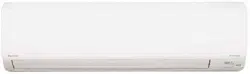
Wall-mounted type
FAQ18TAVJU
FAQ24TAVJU
English
Français
Español
INSTALLATION MANUAL
Read these instructions carefully before installation.
Keep this manual in a handy place for future reference.
This manual should be left with the equipment owner.
Lire soigneusement ces instructions avant l’installation.
Conserver ce manuel à portée de main pour référence
ultérieure.
Ce manuel doit être donné au propriétaire de l’équipement.
Lea cuidadosamente estas instrucciones antes de instalar.
Guarde este manual en un lugar a mano para leer en caso
de tener alguna duda.
Este manual debe permanecer con el propietario del
equipo.
00_CV_3PN07521-5H.indd 1 5/9/2018 9:52:13

SPLIT SYSTEM Air Conditioners Installation manual
1
English
CONTENTS
1. SAFETY CONSIDERATIONS ........................................ 1
2. BEFORE INSTALLATION .............................................. 3
3. SELECTING INSTALLATION SITE................................ 4
4. INDOOR UNIT INSTALLATION ..................................... 5
5. REFRIGERANT PIPING WORK .................................... 8
6. DRAIN PIPING WORK .................................................. 9
7. ELECTRIC WIRING WORK ......................................... 10
8. WIRING EXAMPLE AND HOW TO SET
THE REMOTE CONTROLLER .................................... 11
9. FIELD SETTING .......................................................... 14
10. TEST OPERATION ...................................................... 15
1. SAFETY CONSIDERATIONS
Read these SAFETY CONSIDERATIONS for Installation
carefully before installing air conditioning equipment. After
completing the installation, make sure that the unit operates
properly during the startup operation.
Instruct the customer on how to operate and maintain the
unit. Inform customers that they should store this Installation
Manual with the Operation Manual for future reference.
Always use a licensed installer or contractor to install this
product. Improper installation can result in water or refriger-
ant leakage, electrical shock, re, or explosion.
Meanings of DANGER, WARNING, CAUTION, and NOTE
Symbols:
DANGER
................ Indicates an imminently haz-
ardous situation which, if not
avoided, will result in death or
serious injury.
WARNING
.............. Indicates a potentially haz-
ardous situation which, if not
avoided, could result in death
or serious injury.
CAUTION
............... Indicates a potentially haz-
ardous situation which, if not
avoided, may result in minor
or moderate injury. It may
also be used to alert against
unsafe practices.
NOTE
....................... Indicates situations that may
result in equipment or prop-
erty damage accidents only.
DANGER
• Refrigerant gas is heavier than air and replaces oxy-
gen. A massive leak can lead to oxygen depletion,
especially in basements, and an asphyxiation hazard
could occur leading to serious injury or death.
• Do not ground units to water pipes, gas pipes, tele-
phone wires, or lightning rods as incomplete ground-
ing can cause a severe shock hazard resulting in
severe injury or death. Additionally, grounding to gas
pipes could cause a gas leak and potential explosion
causing severe injury or death.
• If refrigerant gas leaks during installation, ventilate
the area immediately. Refrigerant gas may produce
toxic gas if it comes in contact with re. Exposure to
this gas could cause severe injury or death.
• After completing the installation work, check that the
refrigerant gas does not leak throughout the system.
• Do not install unit in an area where ammable materi-
als are present due to risk of explosions that can
cause serious injury or death.
• Safely dispose of all packing and transportation
materials in accordance with federal/state/local laws
or ordinances. Packing materials such as nails and
other metal or wood parts, including plastic packing
materials used for transportation, may cause injuries
or death by suffocation.
WARNING
• Only qualied personnel must carry out the installa-
tion work. Installation must be done in accordance
with this installation manual. Improper installation
may result in water leakage, electric shock, or re.
• When installing the unit in a small room, take mea-
sures to keep the refrigerant concentration from
exceeding allowable safety limits. Excessive refriger-
ant leaks, in the event of an accident in a closed
ambient space, can lead to oxygen deciency.
• Use only specied accessories and parts for installa-
tion work. Failure to use specied parts may result in
water leakage, electric shocks, re, or the unit falling.
• Install the air conditioner on a foundation strong
enough that it can withstand the weight of the unit. A
foundation of insufcient strength may result in the
unit falling and causing injuries.
• Take into account strong winds, typhoons, or earth-
quakes when installing. Improper installation may
result in the unit falling and causing accidents.
• Make sure that a separate power supply circuit is
provided for this unit and that all electrical work is
carried out by qualied personnel according to local,
state and national regulations. An insufcient power
supply capacity or improper electrical construction
may lead to electric shocks or re.
• Make sure that all wiring is secured, that specied
wires are used, and that no external forces act on the
terminal connections or wires. Improper connections
or installation may result in re.
01_EN_3PN07521-5H.indd 1 7/9/2018 14:13:32
2
English
• When wiring, position the wires so that the control
box cover can be securely fastened. Improper posi-
tioning of the control box cover may result in electric
shocks, re, or the terminals overheating.
• Before touching electrical parts, turn off the unit.
• This equipment can be installed with a Ground-Fault
Circuit Interrupter (GFCI). Although this is a recog-
nized measure for additional protection, with the
grounding system in North America, a dedicated GFCI
is not necessary.
• When installing or relocating the system, keep the
refrigerant circuit free from substances other than the
specied refrigerant (R410A) such as air. Any pres-
ence of air or other foreign substance in the refriger-
ant circuit can cause an abnormal pressure rise or
rupture, resulting in injury.
• Do not change the setting of the protection devices. If
the pressure switch, thermal switch, or other protec-
tion device is shorted and operated forcibly, or parts
other than those specied by Daikin are used, re or
explosion may occur.
CAUTION
• Do not touch the switch with wet ngers. Touching a
switch with wet ngers can cause electric shock.
• Do not allow children to play on or around the unit to
prevent injury.
• Do not touch the refrigerant pipes during and immedi-
ately after operation as the refrigerant pipes may be
hot or cold, depending on the condition of the refrig-
erant owing through the refrigerant piping, compres-
sor, and other refrigerant cycle parts. Your hands may
suffer burns or frostbite if you touch the refrigerant
pipes. To avoid injury, give the pipes time to return to
normal temperature or, if you must touch them, be
sure to wear proper gloves.
• Heat exchanger ns are sharp enough to cut. To avoid
injury, wear glove or cover the ns when working
around them.
• Install drain piping to proper drainage. Improper drain
piping may result in water leakage and property dam-
age.
• Insulate piping to prevent condensation.
• Be careful when transporting the product.
• Do not turn off the power supply immediately after
stopping operation. Always wait for at least 5 minutes
before turning off the power supply. Otherwise, water
leakage may occur.
• Do not use a charging cylinder. Using a charging
cylinder may cause the refrigerant to deteriorate.
• Refrigerant R410A in the system must be kept clean,
dry, and tight.
(a) Clean and Dry -- Foreign materials (including
mineral oils such as SUNISO oil or moisture)
should be prevented from getting into the system.
(b)
Tight -- R410A does not contain any chlorine, does
not destroy the ozone layer, and does not reduce the
earth’s protection again harmful ultraviolet radiation.
R410A can contribute to the greenhouse effect if it is
released. Therefore take proper measures to check
for the tightness of the refrigerant piping installation.
Read the chapter REFRIGERANT PIPING WORK and
follow the procedures.
• Since R410A is a blend, the required additional refrig-
erant must be charged in its liquid state. If the refriger-
ant is charged in a gaseous state, its composition can
change and the system will not work properly.
• The indoor unit is for R410A. See the catalog for
indoor models that can be connected. Normal opera-
tion is not possible when connected to other units.
• Handheld remote controller transmitting distance can
be shorter than expected in rooms with electronic
uorescent lamps (inverter or rapid start types). Install
the indoor unit far away from uorescent lamps as
much as possible.
• Indoor units are for indoor installation only. Outdoor
units can be installed either outdoors or indoors.
• Do not install the air conditioner in the following
locations:
(a) Where a mineral oil mist or oil spray or vapor is
produced, for example, in a kitchen.
Plastic parts may deteriorate and fall off or result
in water leakage.
(b) Where corrosive gas, such as sulfurous acid gas,
is produced.
Corroding copper pipes or soldered parts may
result in refrigerant leakage.
(c) Near machinery emitting electromagnetic waves.
Electromagnetic waves may disturb the operation
of the control system and cause the unit to mal-
function.
(d) Where ammable gas may leak, where there is
carbon ber, or ignitable dust suspension in the
air, or where volatile ammables such as thinner
or gasoline are handled. Operating the unit in
such conditions can cause a re.
NOTE
• Install the power supply and control wires for the
indoor and outdoor units at least 3.5 feet (1.0m) away
from televisions or radios to prevent image interfer-
ence or noise. Depending on the radio waves, a dis-
tance of 3.5 feet (1.0m) may not be sufcient to
eliminate the noise.
• Dismantling the unit, treatment of the refrigerant, oil
and additional parts must be done in accordance with
the relevant local, state, and national regulations.
• Do not use the following tools that are used with
conventional refrigerants: gauge manifold, charge
hose, gas leak detector, reverse ow check valve,
refrigerant charge base, vacuum gauge, or refrigerant
recovery equipment.
• If the conventional refrigerant and refrigerator oil are
mixed in R410A, the refrigerant may deteriorate.
• This air conditioner is an appliance that should not be
accessible to the general public.
• As design pressure is 478 psi (3.3MPa), the wall
thickness of eld-installed pipes should be selected in
accordance with the relevant local, state, and national
regulations.
01_EN_3PN07521-5H.indd 2 7/9/2018 14:13:32
3
English
2. BEFORE INSTALLATION
• When unpacking the unit or moving the unit after
unpacked, be sure to lift it by the four hanger brack-
ets. Avoid putting any pressure on other parts-hori-
zontal aps, the refrigerant piping, drain piping, and
other resin parts.
• Be sure to remove a cushion (corrugated paper) located
between the heat exchanger and the right air lter.
• Be sure to check the type of R410A refrigerant to be used
before installing the unit. (Using an incorrect refrigerant
will prevent normal operation of the unit.)
• The accessories needed for installation must be retained
in your custody until the installation work is completed. Do
not discard them!
• Decide upon a line of transport.
• Leave the unit inside its packaging while moving, until
reaching the installation site. Where unpacking is unavoid-
able, use a sling of soft material or protective plates
together with a rope when lifting, to avoid damage or
scratches to the unit.
• For the installation of an outdoor unit, refer to the installa-
tion manual attached to the outdoor unit.
• When using the wireless remote controller, refer to the
installation manual attached to the wireless remote con-
troller.
• Do not install or operate the unit in rooms mentioned
below.
• Laden with mineral oil, or lled with oil vapor or
spray like in kitchens. (Plastic parts may deteriorate
which could eventually cause the unit to fall out of
place, or could lead to leaks.)
• Where corrosive gas like sulfurous gas exists.
(Copper tubing and brazed spots may corrode
which could eventually lead to refrigerant leaks.)
• Where exposed to combustible gases and where
volatile ammable gas like thinner or gasoline is
used.
(Gas in the vicinity of the unit could ignite.)
• Where machines can generate electromagnetic
waves. (Control system may malfunction.)
• Where the air contains high levels of salt such as
that near the ocean and where voltage uctuates
greatly such as that in factories, vehicles or vessels.
• This unit, both indoor and outdoor, is suitable for installa-
tion in a commercial and light industrial environment. If
installed as a household appliance it could cause electro-
magnetic interference.
WARNING
• Entrust installation to the place of purchase or an autho-
rized serviceman. Improper installation could lead to leaks
and, in worse cases, electric shock of re.
• Use of unspecied parts could lead to the unit falling,
leaks and, in worse cases, electric shock or re.
NOTE
• Be sure to read this manual before installing the indoor
unit.
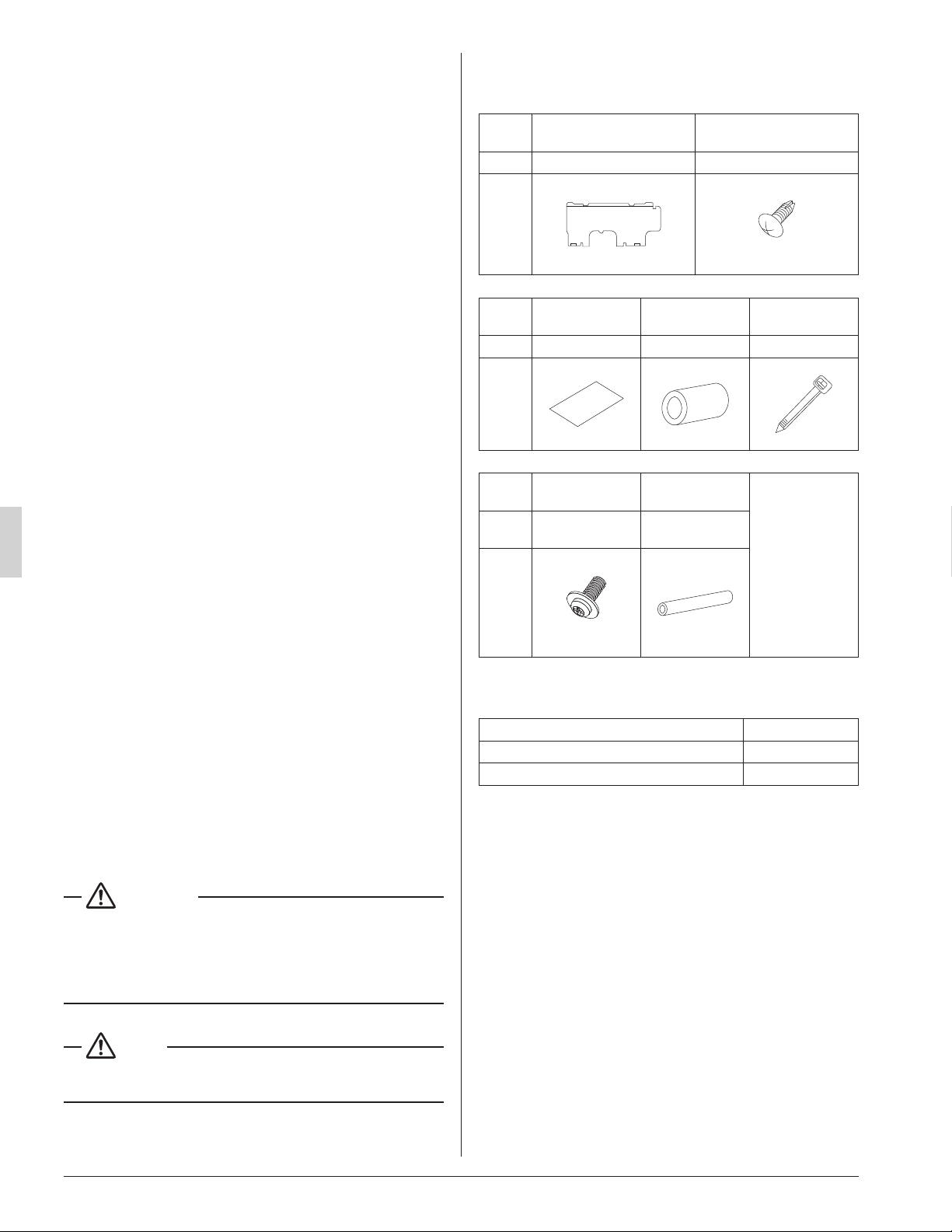
2-1 ACCESSORIES
Check if the following accessories are attached to the
indoor unit.
Name (1) Installation panel
(2) Attachment screw
for the installation panel
Quantity 1 pc. 9 pcs.
Shape
M4 × 25L
Name
(3) Paper pattern
for installation
(4) Insulating
tape
(5) Clamp
Quantity 1 pc. 1 pc. 1 large 4 small
Shape
Name
(6) Securing
screw
(7) Insulating
tube
(Other)
• Operation
manual
• Installation
manual
• Warranty
card
Quantity 2 pcs.
1 long
1 short
Shape
M4 × 12L
2-2 OPTIONAL ACCESSORIES
Remote controller Model
Wired type BRC1E73
Wireless type BRC7E818
01_EN_3PN07521-5H.indd 3 7/9/2018 14:13:33
4
English
FOR THE FOLLOWING ITEMS, TAKE
SPECIAL CARE DURING CONSTRUCTION
AND CHECK AFTER INSTALLATION IS
FINISHED.
(1) Items to be checked after completion of work
Items to be checked
If not properly done,
what is likely to occur
Check
Are the indoor and outdoor
units xed rmly?
The units may drop, vibrate
or make noise.
Is the gas leak test n-
ished?
It may result in insufcient
cooling or heating.
Is the unit fully insulated?
Condensate water may
drip.
Does drainage ow
smoothly?
Condensate water may
drip.
Does the power supply
voltage correspond to that
shown on the name plate?
The unit may malfunction
or the components may
burn out.
Are wiring and piping
correct?
The unit may malfunction
or the components may
burn out.
Is the unit safely
grounded?
It may be dangerous at
electric leakage.
Is wiring size according to
specications?
The unit may malfunction
or the components burn
out.
Is something blocking the
air outlet or inlet of either
the indoor or outdoor unit?
It may result in insufcient
cooling.
Are refrigerant piping
length and additional
refrigerant charge noted
down?
The refrigerant charge in
the system is not clear.
Did you check that no
wiring connection screws
were loose?
Electric shock or re.
Also review the “SAFETY CONSIDERATIONS”
(2) Items to be checked at delivery
Items to be checked Check
Did you explain how to operate the unit while showing
the operation manual to your customer?
Did you give the operation manual over to your cus-
tomer?
2-3 NOTE TO THE INSTALLER
Be sure to instruct customers how to properly operate the
unit (especially cleaning lters, operating different functions,
and adjusting the temperature) by having them carry out
operations themselves while looking at the manual.
3. SELECTING INSTALLATION SITE
(1) Select an installation site where the following condi-
tions are fullled and has the customer’s approval.
•
Where there will be no possible dripping of water from
the refrigerant pipe, drain pipe, etc., in the area between
the unit and ceiling, and in the attic just above the unit.
• Where the wall is strong enough to bear the indoor
unit weight.
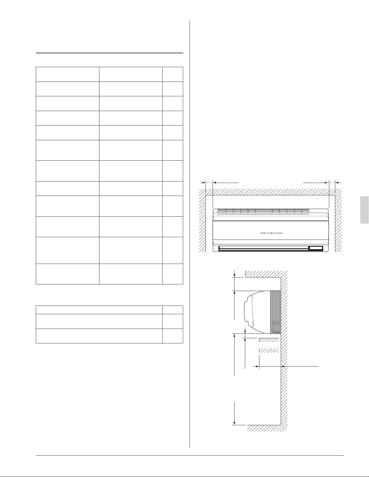
• Where sufcient clearance for installation and mainte-
nance can be ensured.
(Refer to Fig. 1 and Fig. 2)
• Where optimum air distribution can be ensured.
• Where nothing blocks the air passage.
• Where condensate can be properly drained.
• Where the wall is not signicantly tilted.
• Where piping between indoor and outdoor unit is
possible within the allowable limit.
(Refer to the installation manual of the outdoor unit.)
• Install the indoor and outdoor units power supply
wiring and connecting wires at least 3.5ft. (1m) away
from televisions or radios in order to prevent image
interference or noise.
(Depending on the radio waves, a distance of 3.5ft.
(1m) may not be sufcient enough to eliminate the
noise.)
• Where the cool (warm) air reaches all across the
room.
Fig. 1
≥ 2 (50) ≥ 2 (50)
[ Space required for installation [in. (mm)] ]
≥ 3-1/2 (90)
≥ 1-1/4 (30)
Floor
Fig. 2
Obstruction
≤ 4-3/4 (120)
≥ 100 (2500)
(from floor)
For installation
in high places.
01_EN_3PN07521-5H.indd 4 7/9/2018 14:13:33
5
English
(2) Consider whether the place where the unit will be
installed can support the full weight of the unit, and
reinforce it with boards and beams, etc. if needed
before proceeding with the installation. Also, rein-
force the area to prevent vibration and noise before
installing.
(The installation pitch can be found on the paper
pattern for installation (3), so refer to it when consid-
ering the necessity for reinforcing the location.)
(3) The indoor unit may not be directly installed on the
wall. Use the attached installation panel (1) before
installing the unit.
DANGER
• Do not install unit in an area where ammable materials
are present due to risk of explosion resulting in serious
injury or death.
WARNING
• If the supporting structural members are not strong
enough to take the unit’s weight, the unit could fall out of
place and cause serious injury.
4. INDOOR UNIT INSTALLATION
• Use only accessories and parts which are of the desig-
nated specication when installing.
CAUTION
• Install so that the unit does not tilt to either side or forward.
• Do not hold the unit by the horizontal aps when lifting it.
(This may damage the horizontal aps.)
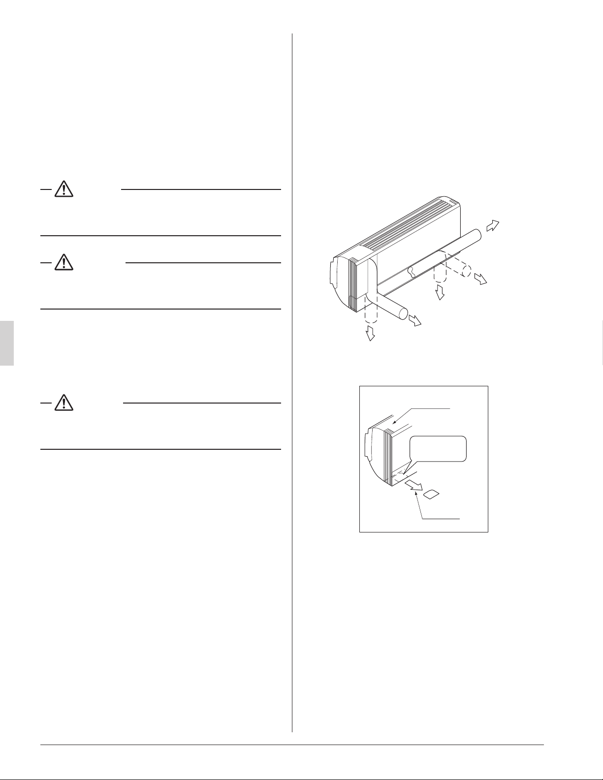
(1) Open the piping through-hole.
• The refrigerant pipe and drain pipe can be routed out
in one of 5 directions: left, bottom-left, back-left,
bottom-right, and back-right. (Refer to Fig. 3)
• Using the paper pattern for installation (3), choose
where to route the piping out of the unit, and drill a
through-hole (f3-1/8” (f80)) in the wall.
Open the hole so that there is a downward slope for
the drain piping. (See “6. DRAIN PIPING WORK”)
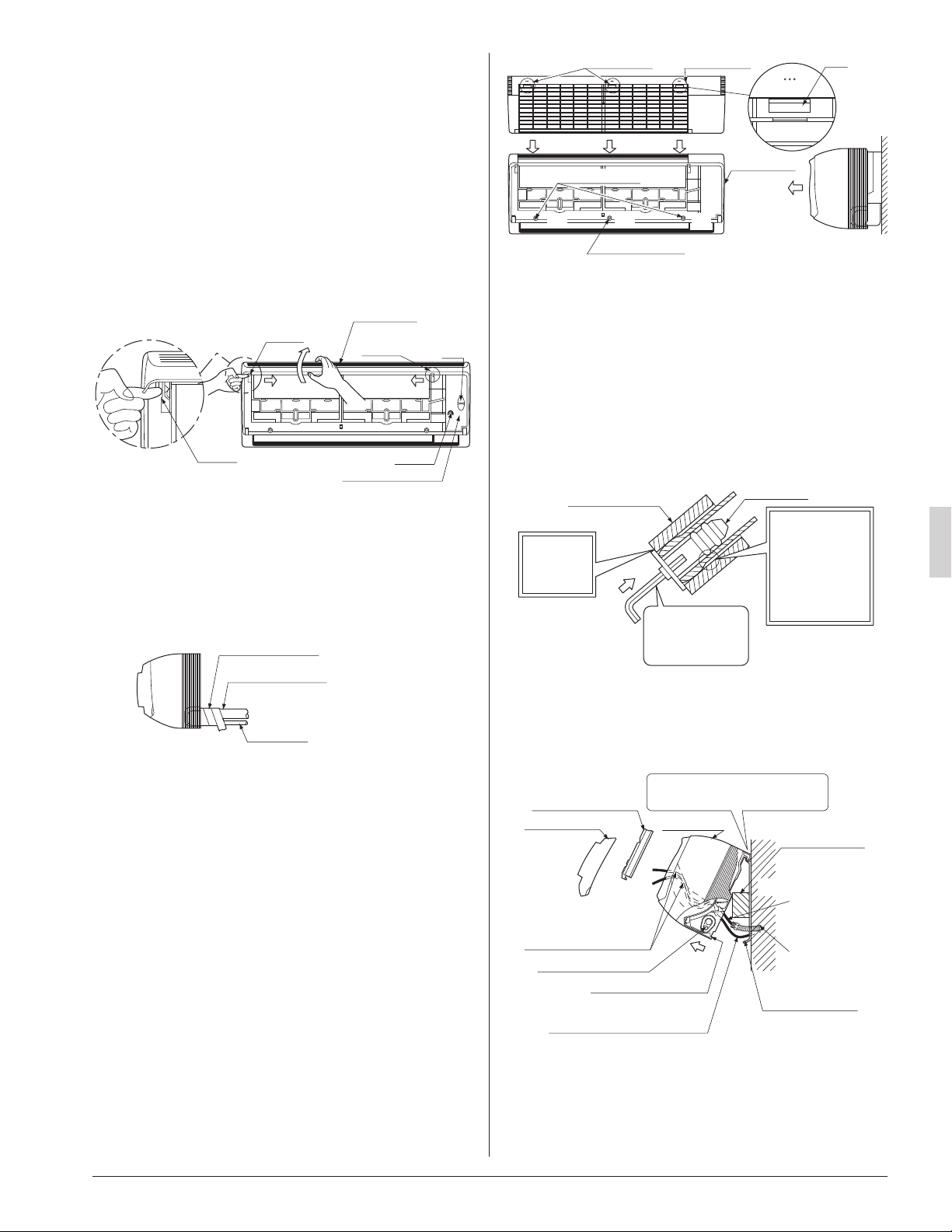
(2) Attach the installation panel (1) to the wall.
(a) Check the location for the hole using the included
paper pattern for installation (3).
• Choose a location so that there is at least a 3-5/8”
(90 mm) gap between the ceiling and the main
unit.
(b) Temporarily attach the installation panel (1) at the
temporary-securing position on the paper pattern for
installation (3) and use a level to make sure the drain
hose is either level or tilted slightly downward.
(c) Secure the installation panel (1) to the wall using
either screws or bolts.
• If using the attachment screws for the installation
panel (2), attach using at least 4 screws on either
side, for a total of 9 screws of the recommended
installation cleat position on the included paper
pattern for installation (3).
• If using bolts, attach using a M8 - M10 bolt or
equivalent (for a total of 2 bolts) on either side.
• If dealing with concrete, use commercially avail-
able foundation bolts (M8 - M10 or equivalent).
(3) If using the left, bottom-left, or bottom-right posi-
tions for the piping, cut out the through-hole for the
piping in the front grille. (Refer to Fig. 4)
Left pipe
Back-left pipe
Back-right pipe
Bottom-left pipe
Bottom-right pipe
Fig. 3
Front grille
Cut away
Fig. 4
Cut out along
the groove.
01_EN_3PN07521-5H.indd 5 7/9/2018 14:13:33
6
English
(4) Remove the front panel and the control box cover.
(Refer to Fig. 5)
< How to remove the front panel and control box
cover >
(1) Open the front panel by lifting from the bottom to the
point where it stops.
(2) Push the panel spacers on either side of the front
panel towards the center of the main unit and
remove.
(You can also remove it by sliding the front panel
either to the left or right and pulling it forward.)
(3) Remove the screw from the control box cover and
pull the tab forward.
Panel
spacer
Panel
spacer
Panel
spacer
Fig. 5
Ta b
Screw
Control box cover
Front panel
(1)
(2) (2)
(3)
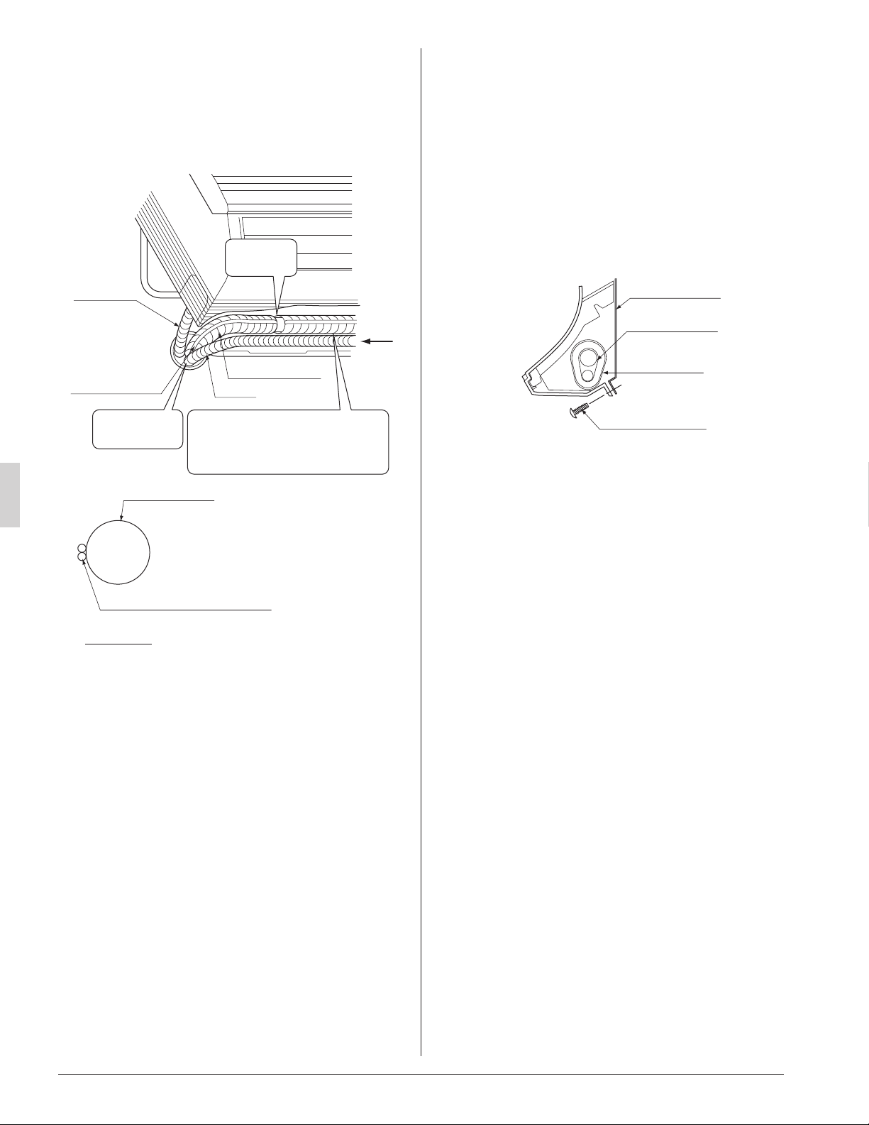
(5) Point the pipe in the direction it will be routed out of
the unit.
For bottom-right and back-right piping
(Refer to Fig. 6)
• Wrap the drain hose and the refrigerant piping
together with the insulating tape (4) so that the drain
hose is below the refrigerant piping.
Insulating tape (4)
Drain hose
Fig. 6
Refrigerant piping
For left, bottom-left, and back-left piping
• Remove the front grille. (Refer to Fig. 7)
< How to remove the front grille >
Remove the front grille as described below when secur-
ing the indoor unit with screws or when attaching
Optional Accessories (wireless remote controller,
adapter PC board, etc.).
(1) Remove the front panel.
(2) Remove the screws (3 places) securing the front
grille.
(3) Remove the tabs (3 places) securing the front grille
by pushing them in the direction of the arrows.
(4) Making sure not to catch the horizontal aps, remove
the front grille by pulling in the direction of the arrow.
Tab position Tab position
Front grille
Fig. 7
Ta b
(2)
(2) (2)
(3) (3)
(4)
(3)
Screw position
Screw position
• Remove the drain plug, the insulating tube, and the drain
hose from the drain pan and replace.
(Refer to Fig. 8)
• Connect the eld refrigerant piping ahead of time, match-
ing it to the liquid pipe and gas pipe marks engraved on
the installation panel (accessory) (1).
< Replacing the drain hose and drain plug >
(1) Remove the drain plug and insulating tube.
(2) Remove the drain hose and replace onto the left side.
(3) Replace the drain plug and the insulating tube onto the
right side.
Drain plug
Insulating tube
Fig. 8
Do not place
lubricant
(refrigerant oil)
when inserting.
This may cause
deterioration and
water leaks.
Insert using a
hexagon wrench
(5/32 in. (4 mm)).
Make sure
there are
no gaps.
(6) Hook the indoor unit onto the installation panel.
(Refer to Fig. 9)
• Placing buffering material between the wall and the
indoor unit at this time will make work easier.
Refrigerant piping
Be sure to pass all
wires through
the wiring guide.
Ta b
(There are 2 places.)
Wiring (locally procured)
Transmission wiring,
Remote controller wiring
Wall
Front panel Front grille
Control box cover
Place buffering
material
Power supply
wiring,
Ground wiring
Conduit
Hook the indoor unit hook onto
the installation panel (1).
Fig. 9
Installation panel
(accessory) (1)
For bottom-right and back-right piping
• Pass the drain hose and the refrigerant piping to the
wall.
01_EN_3PN07521-5H.indd 6 7/9/2018 14:13:34
7
English
(7) Pass power supply wiring from conduit and control
wiring through the wiring guide in the back of the
unit, to the front of the unit. (For connecting the
power supply wiring to the unit, see “8-1 HOW TO
CONNECT WIRINGS”)
(8) Connect the piping. (See “5. REFRIGERANT PIPING
WORK” and Fig. 10)
Secure with
vinyl tape.
Drain hose
Transmission
wiring and remote
controller wiring
Fig. 10
A
A arrow view
Refrigerant piping
Transmission wiring and
remote controller wiring
Refrigerant piping
Conduit
Wrap the insulating tape overlapping
at least half the width with each wrap.
Wrap the insulating tape all the way
to the L-shaped bend.
Seal with putty
corking material.
• Seal the piping through-hole with putty corking mate-
rial.
(9) Push on both bottom edges of the indoor unit using
both hands and hook the tab on the back of the
indoor unit onto the installation panel (1).
(Refer to Fig. 9)
• At this time remove the buffering material placed in
step (6).
• Make sure power supply wiring, transmission wiring,
ground wiring and remote controller wiring are not
caught inside the indoor unit.
When screwing in the indoor unit
• Remove the front grille. (Refer to Fig. 7)
• Secure the indoor unit to the installation panel (1) with
the securing screws (6). (Refer to Fig. 11)
Installation panel
(accessory) (1)
Refrigerant piping
Insulating tape
(accessory) (4)
M4 × 12L
(accessory) (6)
Fig. 11
01_EN_3PN07521-5H.indd 7 7/9/2018 14:13:34
8
English
5. REFRIGERANT PIPING WORK
〈For refrigerant piping of outdoor unit, see the installa-
tion manual attached to the outdoor unit.〉
〈Execute thermal insulation work completely on both
sides of the gas piping and the liquid piping.
Otherwise, a water leak can occur.〉
(When using a heat pump, the temperature of the gas piping
can reach up to approximately 250°F (120°C), so use insula-
tion which is sufciently resistant.)
〈Also, in cases where the temperature and humidity of
the refrigerant piping sections might exceed 86°F (30°C)
or RH80 %, reinforce thermal insulation (13/16 (20mm) or
thicker) for the refrigerant piping. Condensation may
form on the surface of the insulating material.〉
〈Before refrigerant piping work, check which type of
refrigerant is used. Proper operation is not possible if
the type of refrigerant is not the same.〉
DANGER
• Refrigerant gas may produce toxic gas if it comes in
contact with re such as from a fan, heater, stove or
cooking device. Exposure to this gas could result in severe
injury or death.
NOTE
• Use a pipe cutter and a aring tool suitable for the type of
refrigerant.
• To prevent dust, moisture or other foreign matter from
inltrating the tube, either pinch the end or cover it with
tape.
• Do not allow anything other than the designated refriger-
ant to get mixed into the refrigerant circuit, such as air, etc.
• If refrigerant gas leaks while working on the unit, ventilate
the room thoroughly right away.
• The refrigerant is pre-charged in the outdoor unit.
• Use copper alloy seamless pipes.
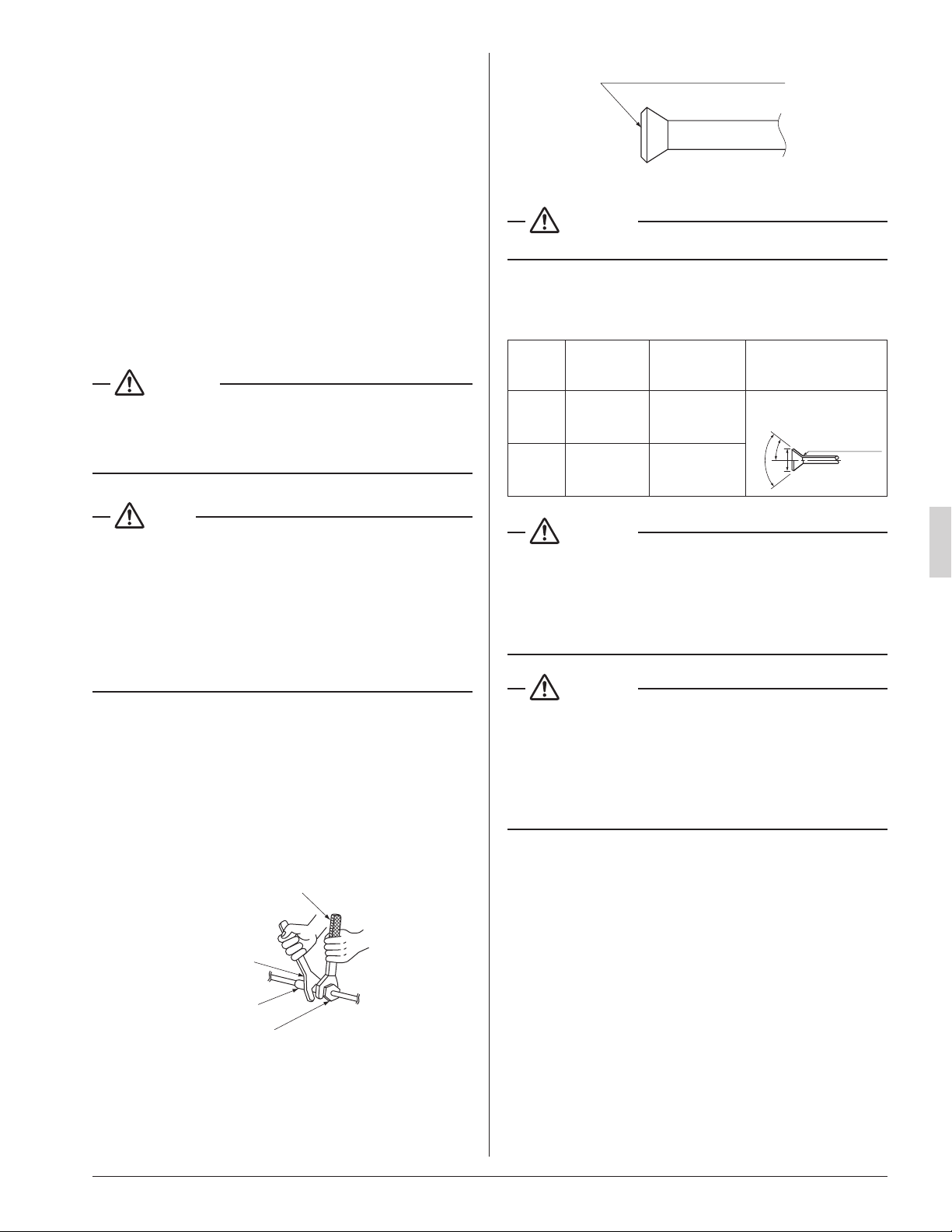
• Be sure to use both a spanner and a torque wrench
together, when connecting or disconnecting pipes to/from
the unit. (Refer to Fig. 12)
• Refer to “Table 1” for the dimensions of are.
• When connecting the are nut, coat the ared inner sur-
face only with ester oil or ether oil, rotate three or four
times rst, then screw in.
(Refer to Fig. 13)
Fig. 12
Torque wrench
Spanner
Union joint
Flare nut
Coat the flared inner surface only
with ester oil or ether oil
Fig. 13
CAUTION
• Use the are nut included with the unit.
• Refer to Table 1 for the corresponding tightening torque.
Table 1
Piping
size
[in. (mm)]
Tightening
torque
[lbf·ft. (N·m)]
Dimension for
processing are
A [in. (mm)]
Flare shape
[in. (mm)]
f 3/8
(9.5)
24.1 – 29.4
(36.3±3.6)
0.504 – 0.520
(13.0±0.2)
R0.016-0.031
(0.4-0.8)
A
90˚±2˚
45˚±2˚
f 5/8
(15.9)
45.6 – 55.6
(68.6±6.8)
0.760 – 0.776
(19.5±0.2)
CAUTION
• Do not excessively tighten the are nut.
Doing so will break the are nut and refrigerant leakage
may occur.
• Make sure that all parts around the are are free of oil.
The drain pan and the resin part may be deteriorated if oil
is attached.
CAUTION
• Do not use ux when brazing refrigerant piping. Therefore,
use the phosphor copper brazing lter metal (BCuP) which
does not require ux.
(Flux has an extremely negative effect on refrigerant
piping systems. For instance, if chlorine based ux is
used, it will cause pipe corrosion. If the ux contains
uorine, it will damage the refrigerant oil.)
01_EN_3PN07521-5H.indd 8 7/9/2018 14:13:34

9
English
• When brazing the refrigerant piping, carry out nitrogen
substitution (inserting nitrogen into the refrigerant piping to
substitute air with nitrogen (refer to NOTE below)) and
then begin brazing. Once this is done, connect the indoor
unit with a are connection.
DANGER
• Use of oxygen may cause an explosion resulting in seri-
ous injury or death. Only use nitrogen gas.
NOTE
• Set nitrogen pressure to about 2.9 psi (0.02 Mpa) with a
pressure-reducing valve if brazing while inserting nitrogen
into the piping. (Refer to Fig. 14)
Refrigerant piping
Part to be
brazed
Taping
Pressure-reducing valve
Hand valve
Nitrogen
Fig. 14
Nitrogen
• After checking for gas leaks, be sure to insulate the pipe
connections using the piping insulating tube and insulating
tape (4). The insulating tape (4) should be wrapped from
the L-shaped bend all the way to the end inside the unit.
(Refer to Fig. 15)
Indoor unit piping insulating
tube
Tape of insulating tube
Seam of Insulating tube
Attach the tape of insulating tube
so that there are no gaps in the
seam of insulating tube.
Fig. 15
Tape of insulating tube
Tape of insulating tube
Field piping
Indoor unit
piping
Indoor unit piping
insulating tube
Clamp (large)
(accessory) (5)
L-shaped
bend
Start wrapping
See “ 4. INDOOR UNIT
INSTALLATION ”
Insulating tape
(accessory) (4)
CAUTION
• Be sure to insulate the eld piping all the way to the piping
connection inside the unit. Any exposed piping may cause
condensate or burns if touched.
6. DRAIN PIPING WORK
(1) Install the drain piping. (Refer to Fig. 16)
• The drain pipe should be short with a downward slope
and should prevent air pockets from forming.
• Watch out for the points in Fig. 16 when performing
drain work.
Fig. 16
Make sure the drain
hose is at a downward
slope.
Make sure the tip is
not under water even
when flooding.
Drain hose Drain hose
(Downward
slope)
• When extending the drain hose, use a commercially
available drain hose for extension, and be sure to
insulate the extended section of the drain hose which
is indoors. (Refer to Fig. 17)
Indoor unit
drain hose
Drain hose for extension
(field supply)
Insulating tube
(field supply)
Insulating tape (accessory) (4)
( See “4. INDOOR UNIT INSTALLATION” )
Fig. 17
• Make sure the diameter of the drain hose for exten-
sion is the same as the indoor unit drain hose (hard
vinyl chloride, I.D. 1/2 in. (13 mm)) or larger.
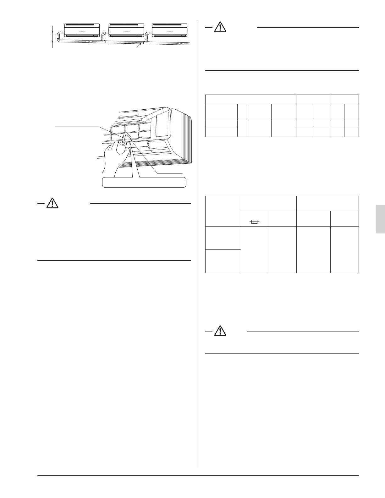
• In case of converging multiple drain hoses, install
them referring to Fig. 18.
• Select diameter of drain hose which adapts to the
capacity of the unit connected.
01_EN_3PN07521-5H.indd 9 7/9/2018 14:13:35
10
English
Fig. 18
(Slope of at least 1/100)
4 in. (100 mm)
or more
(2) Make sure the drain piping works properly.
• After drain piping work is complete, perform a drain-
age check by opening the front panel, removing the
air lter, pouring water into the drain pan, and making
sure water ows smoothly out of the drain hose.
(Refer to Fig. 19)
Plastic container
for pouring
Drain pan
Make sure not to splash the water.
Fig. 19
CAUTION
• Drain piping connections
Do not connect the drain piping directly to sewage pipes
that smell of ammonia. The ammonia in the sewage might
enter the indoor unit through the drain piping and corrode
the heat exchanger.
Keep in mind that it will block the drain pipe and cause
water to collect.
7. ELECTRIC WIRING WORK
7-1 GENERAL INSTRUCTIONS
• All eld supplied parts and materials and electric works
must conform to local codes.
• Use copper wire only.
• For electric wiring work, refer to also “WIRING DIAGRAM”
attached to the unit.
• For details of remote controller wiring, refer to the installa-
tion manual attached to the remote controller.
• All wiring must be performed by an authorized electrician.
• A circuit breaker capable of shutting down power supply to
the entire system must be installed.
• Refer to the installation manual attached to the outdoor
unit for the size of power supply wiring connected to the
outdoor unit, the capacity of the circuit breaker and switch,
and wiring instructions.
• Be sure to ground the air conditioner.
DANGER
• Do not ground units to water pipes, telephone wires or
lightning rods because incomplete grounding could cause
a severe shock hazard resulting in severe injury or death,
and to gas pipes because a gas leak could result in an
explosion which could lead to severe injury or death.
7-2 ELECTRICAL CHARACTERISTICS
Units Power supply Fan motor
Model Hz Volts
Voltage
range
MCA MOP W FLA
FAQ18TAVJU
60 208/230
Max. 253
Min. 187
0.5 15 43 0.4
FAQ24TAVJU
0.6 15 43 0.5
MCA: Minimum Circuit Ampacity (A)
MOP: Maximum Overcurrent Protective Device (A)
W: Fan Motor Rated Output (W)
FLA: Full Load Ampere (A)
7-3 SPECIFICATIONS FOR FIELD SUPPLIED
FUSES AND WIRE
Model
Power supply wiring
Remote controller wiring
Transmission wiring
Fuse
Size Wire Size
FAQ18TAVJU
15A
Wiring size
and length
must
comply
with local
codes.
2-conductor,
stranded
non-shielded
copper cable
PVC/vinyl
jacket
(NOTE)
AWG18-16
(0.75-
1.25 mm
2
)
FAQ24TAVJU
Allowable lengths of transmission wiring and remote controller
wiring are as follows.
(1) Outdoor unit – Indoor unit:
Max. 3280 ft (1,000 m)
(2) Indoor unit – Remote controller:
Max. 1640 ft (500 m)
NOTE
• Vinyl cord with sheath or cable (Insulated thickness :
1/16in. (1 mm) or more)
01_EN_3PN07521-5H.indd 10 7/9/2018 14:13:35
11
English
8. WIRING EXAMPLE AND HOW TO SET
THE REMOTE CONTROLLER
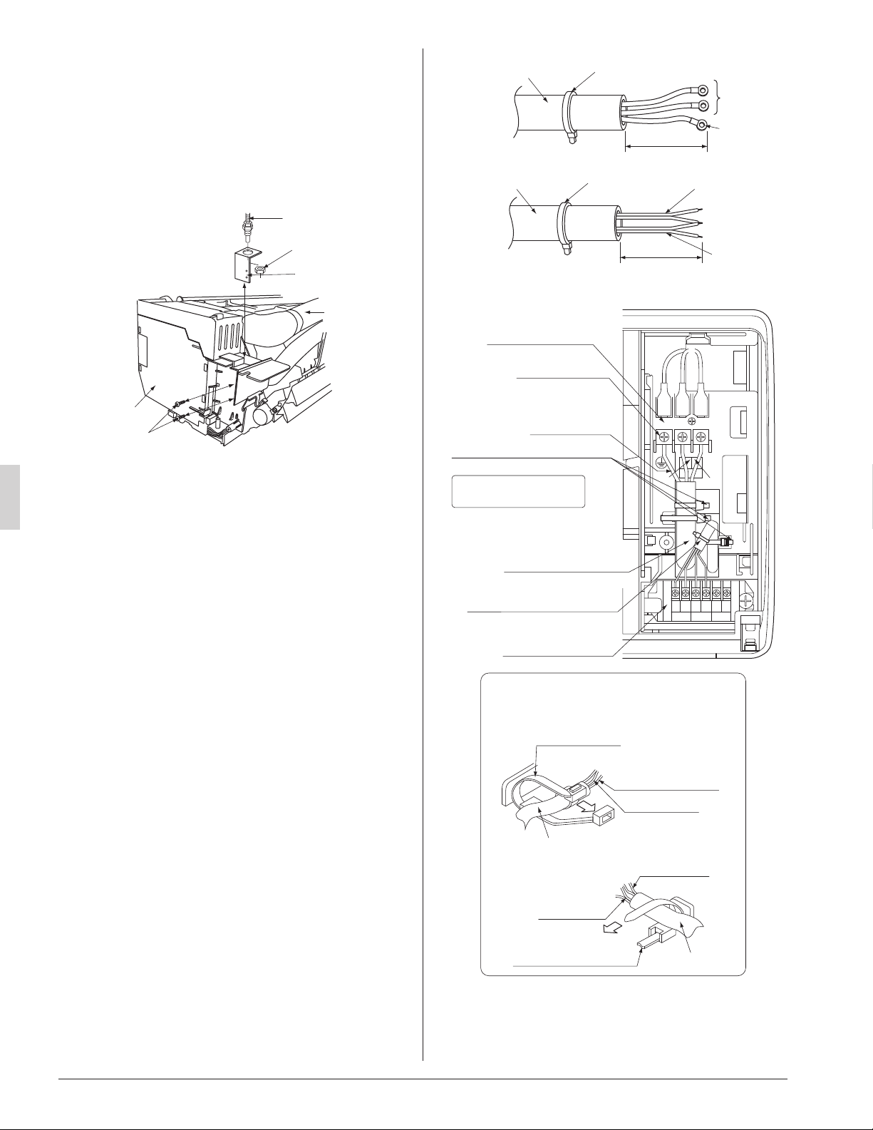
8-1 HOW TO CONNECT WIRINGS
• Conduit for power supply wiring
Unscrew and remove the conduit mounting plate from the
control box. (Refer to Fig. 20)
Fix a conduit to the plate with a lock nut and reattach them
at original position.
Control box
Refrigerant
piping
Conduit
Lock nut
Conduit mounting
plate
Screw
Fig. 20
<Back side>
<Front side>
• Power supply wiring and ground wiring
Unscrew and remove the control box cover.
Thread the power supply wiring and ground wiring through
the included insulating tube (short) (7) and secure them
with the included clamp (small) (5). (Refer to Fig. 21)
Connect the power supply wiring and ground wiring to the
power supply terminal block (3P).
When doing this, rmly secure using the included clamp
(small) (5) according to the gure.
(Refer to Fig. 22)
• Transmission wiring and remote controller wiring
Unscrew and remove the control box cover.
Thread the remote controller wiring and transmission
wiring through the included insulating tube (long) (7) and
secure them with the included clamp (small) (5).
(Refer to Fig. 21)
Connect the remote controller wiring and the transmission
wiring to the terminal block (6P).
When doing this, tie the remote controller wiring and the
transmission wiring using the included clamp (small) (5)
and then rmly secure using the included clamp (small)
(5) according to the gure.
(Refer to Fig. 22)
Fig. 21
Insulating tube (long)
(accessory) (7)
Clamp (small)
(accessory) (5)
Transmission
wiring
Remote
controller
wiring
(1 in. (25 mm))
Insulating tube (short)
(accessory) (7)
Clamp (small)
(accessory) (5)
Power
supply
wiring
Ground
wiring
(1 in. (25 mm))
Fig. 22
Ground wiring
Power supply wiring
Transmission
wiring
<
Wiring clamp method
>
Clamp (small)
(accessory) (5)
Clamp (small)
(accessory) (5)
Remote
controller
wiring
Insulating tube
Insulating tube
REMOTE
CNTRL
FORCED
OFF
TRANSMISSION
WIRING
F1 F2 T1 T2P1 P2
Terminal block (6P)
Ground terminal
Ground wiring
Power supply wiring
Power supply
terminal block (3P)
Remote controller wiring and
transmission wiring
Clamp (small) (accessory) (5)
(3 places)
Cut off any excess
material after tightening.
L1
L2
01_EN_3PN07521-5H.indd 11 7/9/2018 14:13:35
12
English
WARNING
• Never connect power supply wiring to the terminal block
for remote controller wiring as this could damage the
entire system.
• Use only specied wire and connect wires to the terminal
tightly. Be careful wires do not place external stress on
terminals. Keep wires in neat order so as not to obstruct
other equipment. Make sure that the control box cover ts
tightly. Incomplete connections could result in overheating
and, in worse case, result in electric shock or re.
• To avoid a short circuit in the control box, be sure to apply
sealing material or putty (not included) to the wiring hole
to prevent the inltration of water as well as insects or
other small creatures. Otherwise a short-circuit may occur
inside the control box.
CAUTION
• When clamping the wirings, be sure no tension is applied
to the wire connections by using the included clamp. Also,
when wiring, make sure the cover on the control box ts
snugly by arranging the wirings neatly and attaching the
control box cover rmly. When attaching the control box
cover, make sure no wirings get caught in the edges. Pass
wiring through holes to prevent damage to them.
• Make sure the remote controller wiring and transmission
wiring between the units, and other electrical wiring do not
pass through the same locations outside the unit, separat-
ing them by at least 2 in. (50 mm), otherwise electrical
noise (external static) could cause incorrect operation or
breakage.
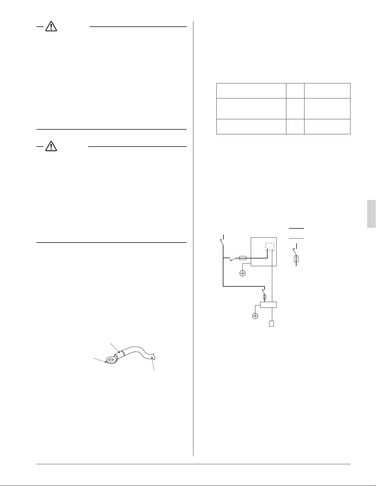
[ PRECAUTIONS ]
1. Use round crimp-style terminals for connecting wires to
the power supply terminal block.
(Refer to Fig. 23)
If unavailable, observe the following points when wiring.
• Do not connect wires of different gauge to the same
power supply terminal.
(Looseness in the connection may cause overheat-
ing.)
• Use the specied electric wire. Connect the wire
securely to the terminal. Lock the wire down without
applying excessive force to the terminal.
Electric wire
Round crimp-style
terminal
Attach insulation sleeve
Fig. 23
2. Tightening torque for the terminal screws.
• Use the correct screwdriver for tightening the terminal
screws. If the blade of screwdriver is too small, the
head of the screw might be damaged, and the screw
will not be properly tightened.
• If the terminal screws are tightened too hard, screws
might be damaged.
• Refer to the table below for the tightening torque of
the terminal screws.
Terminal Size
Tightening torque
[lbf·ft. (N·m)]
Remote controller,
Transmission wiring and
Forced off terminal block (6P)
M3.5
0.59 – 0.71
(0.80 – 0.96)
Power supply and Ground
terminal block (3P)
M4
0.89 – 1.03
(1.2 – 1.4)
3. Do not connect wires of different gauge to the same
ground terminal. Looseness in the connection may
lessen protection.
4. Keep transmission wiring at least 2 in. (50 mm) away
from power supply wiring. The equipment may malfunc-
tion if subjected to electrical (external) noise.
5. For remote controller wiring, refer to the installation
manual attached to the remote controller.
8-2 WIRING EXAMPLE
COMPLETE SYSTEM EXAMPLE
Power supply
Main
switch
Outdoor unit
Power supply wire
Transmission wire
Disconnect switch
Fuse/Breaker
Indoor unit
Remote controller
Fig. 24
01_EN_3PN07521-5H.indd 12 7/9/2018 14:13:35
13
English
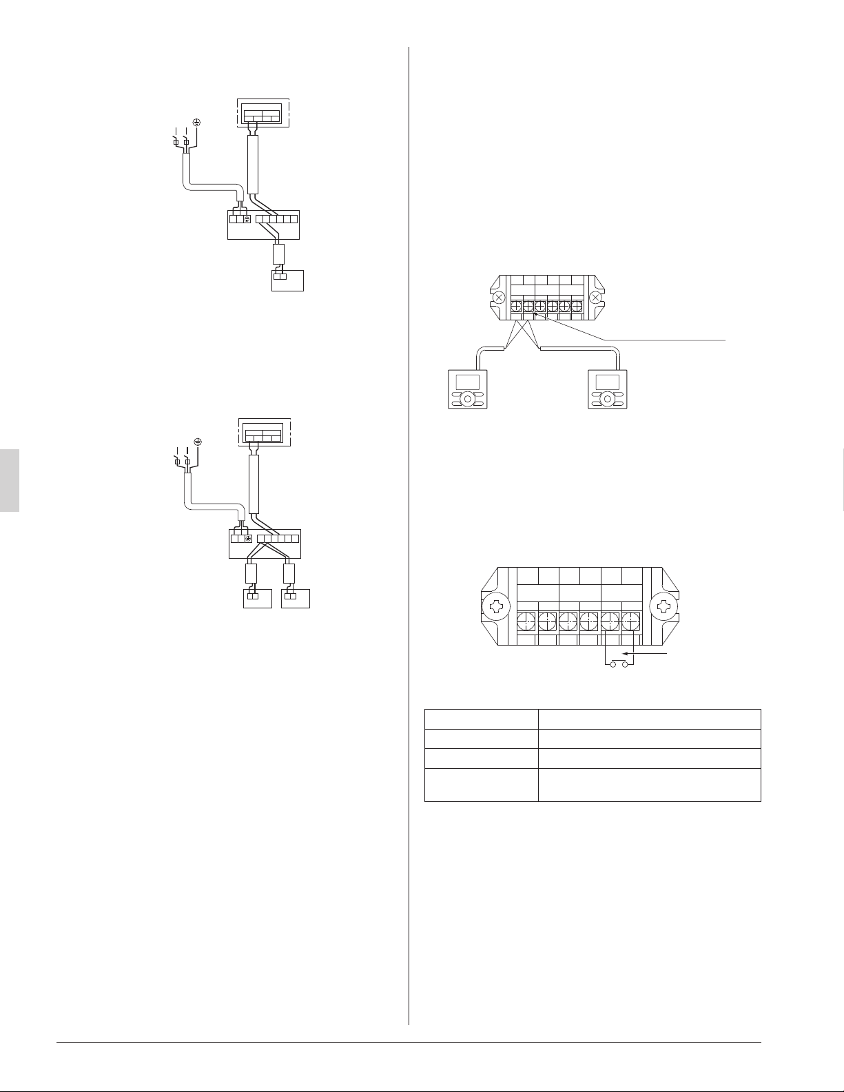
1. When using 1 remote controller (Normal operation)
L1L2
IN/D OUT/D
F
1 F2 F1 F2
P
1
P
2
P
1
P
2
F
1
F
2
T
1
T
2
Control box
Power Supply
208/230V
1~ 60Hz
Outdoor unit
Indoor unit
Remote
controller
L
1
L
2
Fig. 25
2. When using 2 remote controllers
Fig. 26
P
1
P
2
P
1
P
2
L1L2
IN/D OUT/D
F
1 F2 F1 F2
P
1
P
2
F
1
F
2
T
1
T
2
Control box
For use with
2 remote
controllers
Power Supply
208/230V
1~ 60Hz
Outdoor unit
Indoor unit
L
1
L
2
[ PRECAUTIONS ]
1. Do not ground the equipment on gas pipes, water pipes
or lightning rods, or crossground with telephones.
Improper grounding could result in electric shock.
2. The remote controller wiring (P
¹
and P
²
) and transmis-
sion wiring (F
¹
and F
²
) have no polarity.
8-3 CONTROL BY 2 REMOTE
CONTROLLERS (Controlling 1 indoor unit by 2
remote controllers)
• When using 2 remote controllers, one must be set to
“MAIN” and the other to “SUB”.
〈Main/sub changeover〉
• Refer to the installation manual supplied with the remote
controller.
〈Wiring method〉
(1) Remove the control box cover.
(2) Add the remote controller 2 (SUB) to the terminal block
for remote controller (P
¹
, P
²
) in the control box. (There is
no polarity.)
Remote controller wiring
terminal block
Remote
controller 2
(SUB)
Remote
controller 1
(MAIN)
1
P
2
P
1
F
2
F
1
T
2
T
FORCED
OFF
REMOTE
CONTRL
TRANSMISSION
WIRING
Fig. 27
8-4 REMOTE CONTROL (FORCED OFF AND ON/
OFF OPERATION)
• Connect input lines from the outside to the terminals T
¹
and T
²
on the terminal block (6P) for remote controller to
achieve remote control.
• See “9. FIELD SETTING” for details on operation.
Input A
1
P
2
P
1
F
2
F
1
T
2
T
FORCED
OFF
REMOTE
CONTRL
TRANSMISSION
WIRING
Fig. 28
Wire specication Sheathed vinyl cord or 2 core cable
Gauge AWG18 – 16 (0.75-1.25 mm
2
)
Length Max. 328 ft. (100 m)
External terminal
Contact that can ensure the minimum
applicable load of 15 V DC, 1 mA.
8-5 CENTRALIZED CONTROL
• For centralized control, it is necessary to designate the
group No. For details, refer to the manual of each optional
controllers for centralized control.
01_EN_3PN07521-5H.indd 13 7/9/2018 14:13:36
14
English
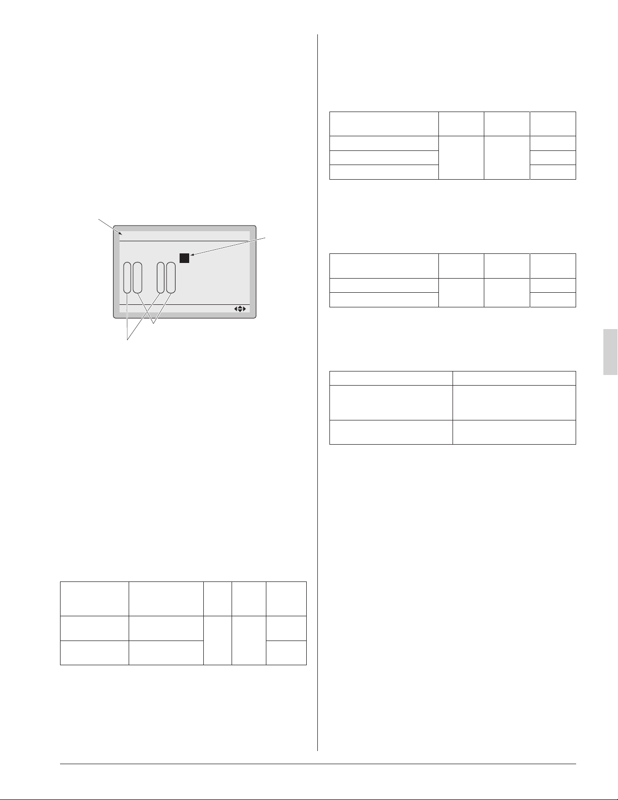
9. FIELD SETTING
〈Field settings may have to be performed using the
remote controller, depending on the type of installation.〉
(1) Make sure the control box covers are closed on the
indoor and outdoor units.
(2) Depending on the type of installation, make the eld
settings from the remote controller after the power is
turned on, following the installation manual attached
to the remote controller.
• The settings can select “Mode No.”, “FIRST CODE
NO.” and “SECOND CODE NO.”.
• The “Field Settings” included with the remote control-
ler lists the order of the settings and method of opera-
tion.
0
Unit No.
1
–
01
5
–––
9
–––
2
–
02
6
–––
a
–––
3
–
01
7
–––
b
–––
Field Settings
0
–
01
4
–––
8
–––
Setting
Mode
20
SECOND CODE NO.
FIRST CODE NO.
Mode No.
FIELD SET MODE
Fig. 29
• Lastly, make sure the customer keeps the installation
manual, along with the operating manual, in a safe place.
〈When using wireless remote controllers〉
• When using wireless remote controllers, wireless remote
controller address setting is necessary. Refer to the instal-
lation manual attached to the wireless remote controller
for setting instructions.
9-1 SETTING FILTER SIGN
• Remote controllers are equipped with display air lter
signs to display the time to clean air lters.
• Change the SECOND CODE NO. according to Table 2
depending on the amount of dirt or dust in the room.
(SECOND CODE NO. is factory set to “01” for air lter
contamination-light)
Table 2
Setting
Spacing time of
display air lter
sign
Mode
No.
FIRST
CODE
NO.
SECOND
CODE
NO.
Air lter contami-
nation-light
Approx. 200hours
20 0
01
Air lter contami-
nation-heavy
Approx. 100hours 02
9-2 SETTING AIRFLOW RATE INCREASE MODE
• It is possible to raise set airow (HIGH and LOW) from the
eld. Change the SECOND CODE NO. as shown in
Table3 to suit your needs.
(SECOND CODE NO. is factory set to “01” for Standard.)
Table 3
Setting Mode No.
FIRST
CODE NO.
SECOND
CODE NO.
Standard
23 0
01
A little increase 02
Increase 02
9-3 REMOTE CONTROL SETTING
• Forced off and ON/OFF operation should be selected by
selecting the SECOND CODE NO. as shown in Table 4.
Table 4
External ON/OFF input Mode No.
FIRST
CODE NO.
SECOND
CODE NO.
Forced off
22 1
01*
ON/OFF operation 02
* Factory set
• Input A of forced off and ON/OFF operation work as
shown in Table 5.
Table 5
Forced off ON/OFF operation
Input A “on” to force a stop
(remote controller reception
prohibited)
Unit operated by changing input
A from “off” to “on”
Input A “off” to allow remote
controller
Unit stopped by changing input
A from “on” to “off”
01_EN_3PN07521-5H.indd 14 7/9/2018 14:13:36
15
English
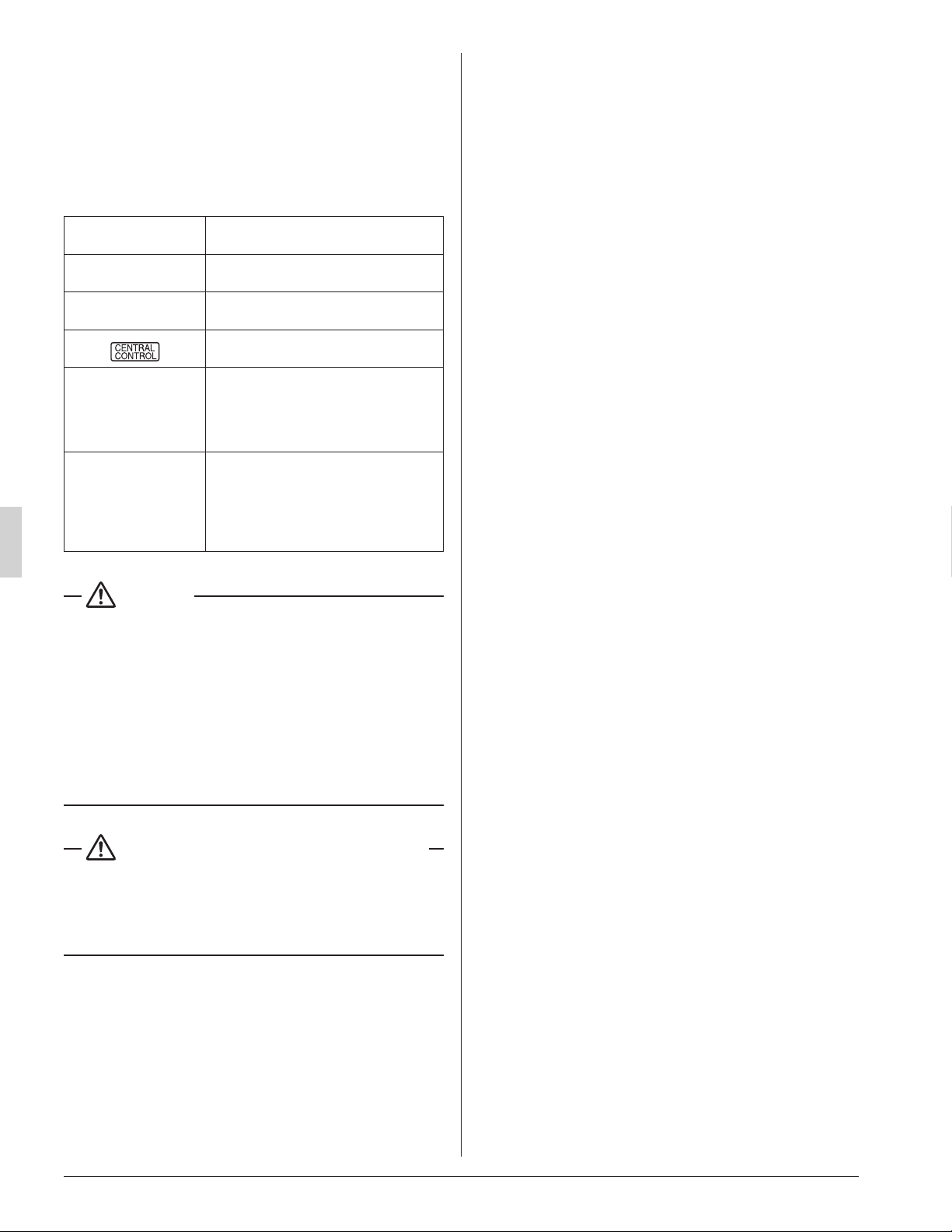
10. TEST OPERATION
• The operation lamp of the remote controller will ash when
a malfunction occurs. Check the malfunction code on the
display to identify the point of trouble. An explanation of
malfunction codes and the corresponding trouble is pro-
vided in “Service precautions” of the outdoor unit.
If the display shows any of the following, there is a pos-
sibility that the wiring was done incorrectly or that the
power is not on, so check again.
Remote controller
display
Contents
“ A8 ”
• Error in power supply voltage to indoor
unit.
“ U3 ”
• Test operation of outdoor unit has not
been nished.
“
”
• There is a short circuit at the FORCED
OFF terminals (T
¹
, T
²
)
“ U4 ”
“ UH ”
• The power on the outdoor unit is off.
• The outdoor unit has not been wired for
power supply.
• Incorrect wiring for the transmission
wiring and / or FORCED OFF wiring.
None
• The power on the indoor unit is off.
• The indoor unit has not been wired for
power supply.
• Incorrect wiring for the remote controller
wiring, the transmission wiring and / or
the FORCED OFF wiring.
CAUTION
• After the test operation is completed, check the items
mentioned in 2. BEFORE INSTALLATION (2) Items to be
checked at delivery on page 4.
If the interior nish work is not completed when the test
operation is nished, for protection of the air conditioner,
ask the customer not to operate the air conditioner until
the interior nish work is completed.
If the air conditioner is operated, the inside of the indoor
unit may be polluted by substances generated from the
coating and adhesives used for the interior nish work and
cause water splash and leakage.
To the operator carrying out test operation
• After the test operation is completed, before delivering the
air conditioner to the customer, conrm that the control
box cover, the air lter and suction grille are attached.
In addition, explain the power supply status (power supply
ON/OFF) to the customer.
01_EN_3PN07521-5H.indd 15 7/9/2018 14:13:36
5151 San Felipe, Suite 500
Houston, TX 77056
(1809)
HT
3PN07521-5H
EM17A032
00_CV_3PN07521-5H.indd 2 5/9/2018 9:52:13