Loading ...
Loading ...
Loading ...
Part number 550-100-260/0520
18
ECO
®
Tec
GAS-FIRED WATER BOILER – 80/110/150/199 BOILER MANUAL
Gas conversions (continued)
LP to Natural gas conversion
1. Follow the same instructions as LP conversion, except using
the correct Natural gas conversion kit, See page 15 .
2. If LP gas was already selected in the boiler control, the gas
type parameter will need to be adjusted. In the contractor
menu, under the Boiler Settings menu, adjust the “Fuel Type”
setting to “Natural Gas”.
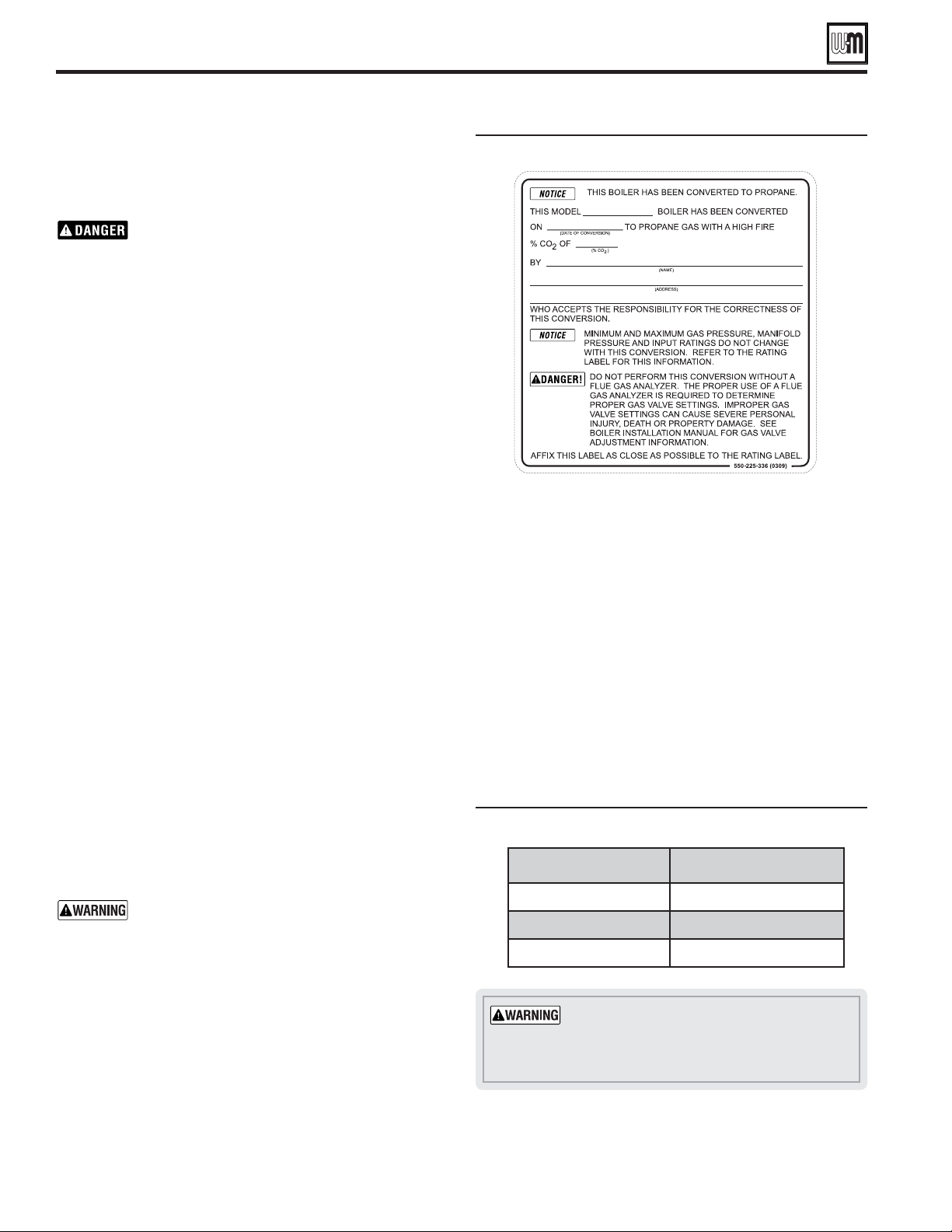
3. Turn throttle screw clockwise until it stops, and then turn
counter-clockwise number of turns per Figure 22. Figure 22
is intended to make rough adjustment to gas valve to allow
the boiler to fire. They are NOT intended to replace proper
adjustment of combustion valves per instructions on
pages 102 and 103 of this manual.
4. Natural gas boilers do not require an orifice between the
gas pipe and the venturi.
DO NOT operate the boiler with
the jacket door removed except for inspection
and testing as directed in this manual.
Boiler Model Number of Turns
80/110 NG
150 NG 12
199 NG 14-½
Installer conversion label
Throttle screw adjustment
3. Prior to turning on the boiler, review the procedure and
control sequence for the operation of the Manual Test Mode
in the section of the Boiler Manual titled “Manual Test Mode”
starting on page 112.
The use of a flue gas analyzer is required to convert
this unit and determine proper gas valve settings.
Do not perform this conversion without a flue gas
analyzer. Improper gas valve settings can cause
severe personal injury, death, or property damage.
4. Do NOT allow the boiler to modulate freely until the
combustion analysis and adjustment is complete. Turn on and
connect properly working, calibrated combustion analyzer to
the boiler flue pipe. Fire the boiler and force it to High Fire
in Manual Test Mode. Adjust the high fire combustion first,
using the throttle adjustment screw, to the CO
2
and CO ranges
specified in Figure 94, page 103, by model size. Then, force
the boiler to Low Fire and adjust the offset regulating screw
to the CO
2
and CO ranges specified in Figure 94, page 103,
by model size. Reinstall the cap over the offset adjustment
screw. Follow the full startup instructions found in this Boiler
Manual including the section titled “Re-check the Maximum
and Minimum CO
2
and CO rate” on page 103.
5. The coarse adjustment prescribed by this manual should
result in combustion settings that allow for ignition and
are a starting point for further adjustment. If, after making
the coarse adjustments prescribed above, the boiler will not
light, turn the throttle screw only counterclockwise (4) an
additional 1/4 turn and attempt to light again. Repeat for a
total of up to one full turn. If, after following the procedure
above, the boiler still will not ignite or, during combustion
analysis, the analyzer reads less than 1.0% O
2
, contact Weil-
McLain Technical Services for assistance.
6. Check for gas leaks and confirming proper performance.
Perform Boiler Manual start-up
Perform complete start-up sequence (beginning on page 97),
including check for gas leaks and checking for proper operation.
After placing the boiler in operation, the ignition system safety
shutoff device must be tested, page 103.
Install front door
Install front door after servicing. The front door
must be securely fastened to the boiler frame to
prevent boiler from drawing air from inside the
boiler room. This is particularly important if
the boiler is located in the same room as other
appliances. Failure to keep the door securely fastened
could result in severe personal injury or death.
Apply installer conversion label
1. After installation is complete and boiler is set up for propane
gas, fill out and attach the propane conversion label next to
the boiler rating label (right side of cabinet).
2. Contractor/installer is responsible for completing the
information required on label (provided in kit) and attaching
installer conversion label next to the boiler rating label.
Loading ...
Loading ...
Loading ...