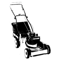
Owner's Manual
ICRRFTSMRN°I
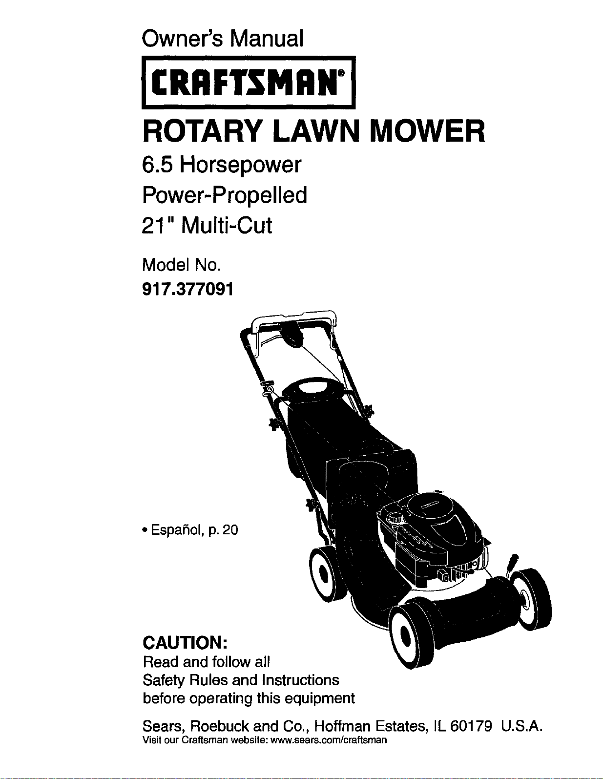
ROTARY LAWN MOWER
6.5 Horsepower
Power-Propelled
21" Multi-Cut
Model No.
917.377091
• EspaSol, p. 20
CAUTION:
Read and follow all
Safety Rules and Instructions
before operating this equipment
Sears, Roebuck and Co., Hoffman Estates, IL 60179 U.S.A.
Visit our Craftsman website: www.sears.com/craftsman

Warranty ................................................... 2
Safety Rules .......................................... 2-4
Product Specifications .............................. 4
Assembly / Pre-Operation ..................... 5-6
Operation ............................................ 7-11
Maintenance Schedule ........................... 12
Maintenance ...................................... 12-15
Service and Adjustments ................... 15-17
Storage .............................................. 17-18
Troubleshooting ................................. 18-19
Repair Parts ....................................... 38-47
Sears Service .......................... Back Cover
LIMITED TWO YEAR WARRANTY ON CRAFTSMAN POWER MOWER
For two years from date of purchase, when this Craftsman Lawn Mower is maintained,
lubricated, and tuned up according to the operating and maintenance instructions in the
owner's manual, Sears will repair free of charge any defect in material or workmanship.
If this Craftsman Lawn Mower is used for commercial or rental purposes, this warranty
applies for only 90 days from the date of purchase.
This Warranty does not cover:
• Expendable items which become worn during normal use, such as rotary mower
blades, blade adapters, belts, air cleaners and spark plug.
• Repairs necessary because of operator abuse or negligence, including bent crank-
shafts and the failure to maintain the equipment according to the instructions con-
tained in the owner's manual.
Warranty service is available by returning the Craftsman power mower to the nearest Sears
Parts & Repair Center in the United States. This warranty applies only while this product
is used in the United States.
This Warranty gives you specific legal rights, and you may also have other rights which
vary from state to state.
Sears, Roebuck And Co., D/817 WA, Hoffman Estates, IL 60179
IMPORTANT: This cutting machine is capable of amputating hands and feet and throwing ob-
jects. Failure to observe the following safety instructions could result in serious injury or death.
_kLookfor this symbol to point out important A CAUTION: Muffler and
safety precautions. It means CAUTION! BE- other engine parts become _[_ ,,
COMEALERT!YOURSAFETYISINVOLVED. extremely hotduring
AWARNING: In orderto prevent accidental operation and remain hot
starting when setting up, transporting, ad-
justing or making repairs, always disconnect
spark plug wire and place wire where it cannot
come in contact with plug.
AWARNING: Engine exhaust, some of its
constituents, and certain vehicle components
contain or emit chemicals known tothe State
of California tocause cancer and birthdefects
_,wAotherreproductive harm.
RNING: Battery posts, terminals and
related accessories contain lead and lead
compounds, chemicals known to the State
of California to cause cancer and birth
defects or other reproductive harm. Wash
hands after handling.
after engine has stopped. To
avoid severe burns on contact,
stay away from these areas.
I. GENERAL OPERATION
• Read, understand, and follow all
instructions on the machine and in the
manual(s) before starting. Be thoroughly
familiar with the controls and the proper
use of the machine before starting.
• Do not put hands or feet near or under
rotating parts. Keep clear of the dis-
charge opening at all times.
• Only allow responsible individuals, familiar
2 withtheinstructions,tooperatethemachine.
• Clear the area of objects such as rocks,
toys, wire, bones, sticks, etc., which
could be picked up and thrown by blade.
• Be sure the area is clear of other people
before mowing. Stop machine if anyone
enters the area.
• Do not operate the mower when bare-
foot or wearing open sandals. Always
wear substantial foot wear.
• Do not pull mower backwards unless ab-
solutely necessary. Always took down and
behind before and while moving backwards.
• Never direct discharged material toward
anyone. Avoid discharging material against
a wall or obstruction. Material may richo-
chet back toward the operator. Stop the
blade when crossing gravel surfaces.
• Do not operate the mower without
proper guards, plates, grass catcher or
other safety protective devices in place.
• See manufacturer's instructions for
proper operation and installation of
accessories. Only use accessories ap-
proved by the manufacturer.
• Stop the blade(s) when crossing gravel
drives, walks, or roads.
• Stop the engine (motor) whenever you
leave the equipment, before cleaning the
mower or unclogging the chute.
• Shut the engine (motor) off and wait until
the blade comes to complete stop before
removing grass catcher.
Mow only in daylight / good artificial light.
Do not operate the machine while under
the influence of alcohol or drugs.
• Never operate machine in wet grass.
Always be sure of your footing: keep a
firm hold on the handle; walk, never run.
• Disengage the self-propelled mech-
anism or drive clutch on mowers so
equipped before starting the engine.
• If the equipment should start to vibrate
abnormally, stop the engine (motor) and
check immediately for the cause. Vibra-
tion is generally a warning of trouble.
• Alwayswear safety goggles or safety glass-
es with side shields when operating mower.
II. SLOPE OPERATION
Slopes are a major factor related to slip &
fall accidents which can result in severe in-
jury.All slopes require extra caution. If you
feel uneasy on a slope, do not mow it.
DO:
Q Mow across the face of slopes: never
up and down. Exercise extreme caution
when changing direction on slopes.
• Remove obstacles such as rocks, tree
limbs, etc.
• Watch for holes, ruts, or bumps.Tail
grass can hide obstacles.
DO NOT:
• Do not trim near drop-offs, ditches or
embankments. The operator could lose
footing or balance.
• Do not trim excessively steep slopes.
• Do not mow on wet grass. Reduced foot
ing could cause slipping.
III. CHILDREN
Tragic accidents can occur if the operator
is not alert to the presence of children.
Children are often attracted to the machin_
and the mowing activity. Never assume
that children will remain where you last
saw them.
• Keep children out of the trimming area
and under the watchful care of another
responsible adult.
• Be alert and turn machine off if children
enter the area.
• Before and while walking backwards,
look behind and down for small children.
• Never allow children to operate mower.
• Usa extra care when approaching blind
corners, shrubs, trees, or other objects
that may obscure vision.
IV. SAFE HANDLING OF GASOLINE
Use extreme care in handling gasoline.
Gasoline is extremely flammable and the
vapors are explosive.
• Extinguish all cigarettes, cigars, pipes
and other sources of ignition.
• Use only an approved container.
• Never remove gas cap or add fuel with
the engine running. Allow engine to cool
before refueling.
• Never refuel the machine indoors.
• Never store the machine or fuel contain-
er where there is an open flame, spark
or pilot light such as a water heater or or
other appliances.
• Never fill containers inside a vehicle, on
a truck or trailer bed with a plastic liner.
Always place containers on the ground
away from your vehicle before fil_ing.
• Remove gas-powered equipment from
the truck or trailer and refuel iton the
ground. If this is not possible, then
refuel such equipment with a portable
container, rather than from a gasoline
dispenser nozzle.
• Keep the nozzle in contact with the rim
of the fuel tank or container opening at
all times until fueling is complete. Do not
use a nozzle lock-open device.
• If fuel is spilled on clothing, change
clothing immediately.
• Never overfill fuel tank. Replace ga_ cap
and tighten securely.
3
V, GENERAL SERVICE
• Never run machine inside a closed area.
• Never make adjustments or repairs with
the engine (motor) running. Disconnectthe
spark plug wire, and keep the wire away
from plug to prevent accidental starting.
• Keep nuts and bolts, especially blade
attachment bolts, tight and keep equip-
ment in good condition.
• Never tamper with safety devices. Check
their proper operation regularly.
• Keep machine free of grass, leaves, or
other debris build-up. Clean oilorfuel spill-
age. Allow machine to cool before storing.
• Stop and inspect the equipment if you
strike an object. Repair, if necessary,
before restarting.
• Never attempt to make wheel height
adjustments while the engine is running.
• Grass catcher components are subject
to wear, damage, and deterioration,
which could expose moving parts or
allow objects to be thrown. Frequently
check components and replace with
manufacturer's recommended parts,
when necessary.
• Mower blades are sharp and can cut.
Wrap the blade(s) or wear gloves, and
use extra caution when servicing them.
• Do not change the engine governor set-
ting or overspeed the engine.
• Maintain or replace safety and instruc-
tion labels, as necessary.
Serial Number:
Date of Purchase:
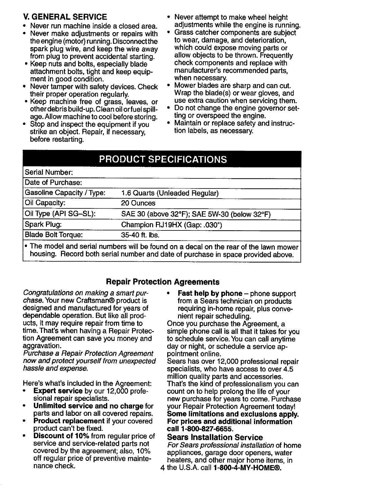
Gasoline Capacity /Type: 1.6 Quarts (Unleaded Regular)
Oil Capacity: 20 Ounces
Oil Type (API SG-SL): SAE 30 (above 32°F); SAE 5W-30 (below 32°F)
Spark Plug: Champion RJ19HX (Gap: .030")
Blade Bolt Torque: 35-40 ft. Ibs.
• The model and serial numbers will be found on a decal on the roar of the lawn mower
housing. Record both serial number and date of purchase in space provided above.
Repair Protection Agreements
Congratulations on making a smart pur-
chase. Your new Craftsman® product is
designed and manufactured for years of
dependable operation. But like all prod-
ucts, it may require repair from time to
time. That's when having a Repair Protec-
tion Agreement can save you money and
aggravation.
Purchase a Repair Protection Agreement
now and protect yourself from unexpected
hassle and expense.
Here's what's included in the Agreement:
• Expert service by our 12,000 profe-
sional repair specialists.
• Unlimited service and no charge for
parts and labor on all covered repairs.
• Product replacement ifyour covered
product can't be fixed.
• Discount of 10% from regular price of
service and service-related parts not
covered by the agreement; also, 10%
off regular price of preventive mainte-
nance check.
• Fast help by phone - phone support
from a Sears technician on products
requiring in-home repair, plus conve-
nient repair scheduling.
Once you purchase the Agreement, a
simple phone call is all that it takes for you
to schedule service. You can call anytime
day or night, or schedule a service ap-
pointment online.
Sears has over 12,000 professional repair
specialists, who have access to over 4.5
million quality parts and accessories.
That's the kind of professionalism you can
count on to help prolong the life of your
new purchase for years to come. Purchase
your Repair Protection Agreement today!
Some limitations and exclusions apply.
For prices and additional information
call 1-800-827-6655.
Sears Installation Service
For Sears professional installation of home
appliances, garage door openers, water
heaters, and other major home items, in
4 the U.S.A. call 1-800-4-MY-HOME®.
AWARNING: This lawn mower is equipped with an internal combustion engine and
should not be used on or near any unimproved forest-covered, brush-covered or
grass-covered land unless the engine's exhaust system is equipped with a spark
arrester meeting applicable local or state laws (if any). If a spark arrester is used, it
should be maintained in effective working order by the operator.
In the state of California the above is required by law (Section 4442 of the California
Public Resources Code). Other states may have similar laws. Federal laws apply on
federal lands. A spark arrester for the muffler is available through your nearest Sears
Parts & Repair Center (See the REPAIR PARTS section of this manual).
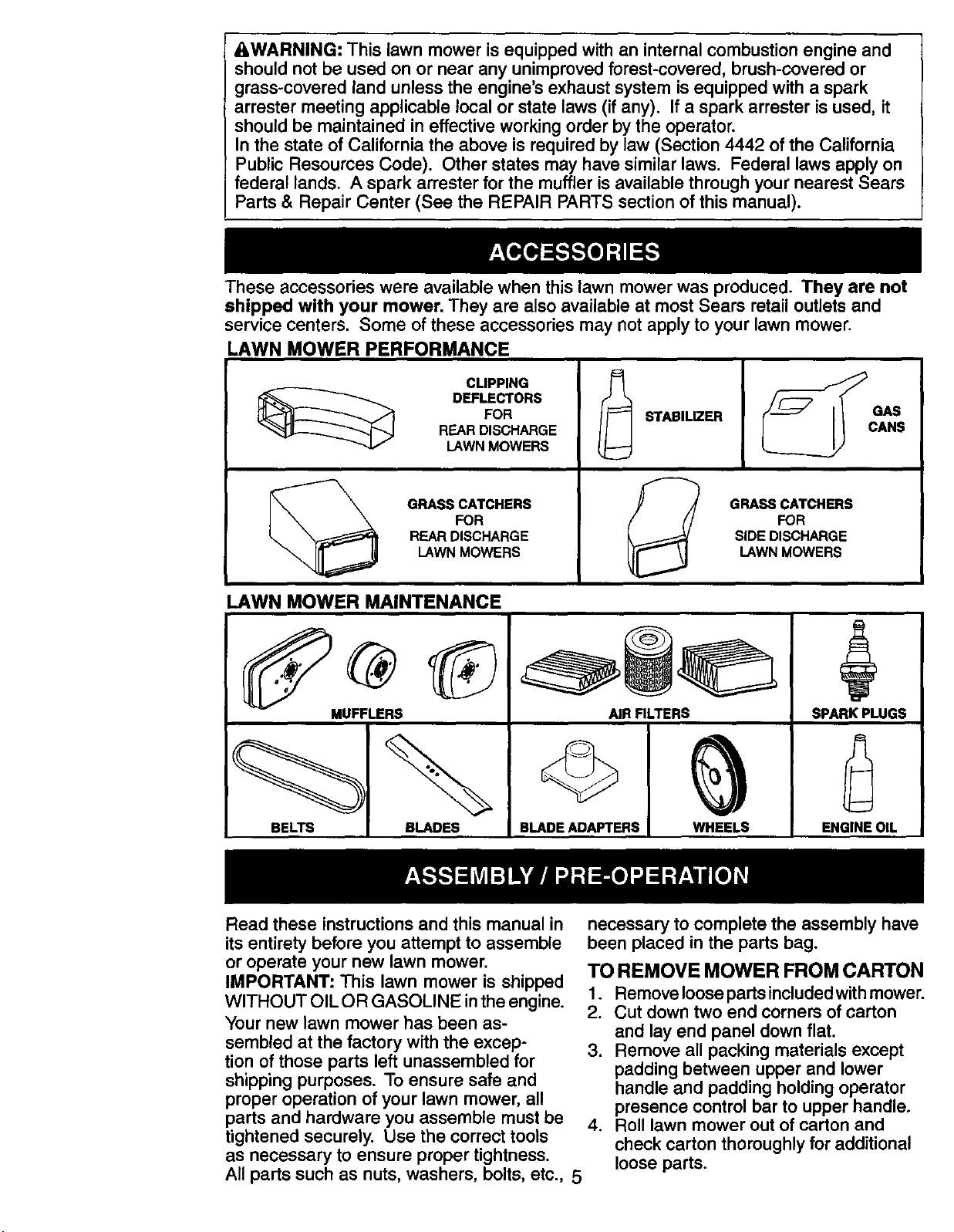
These accessories were available when this lawn mower was produced. They are not
shipped with your mower. They are also available at most Sears retail outlets and
service centers. Some of these accessories may not apply to your lawn mower.
LAWN MOWER PERFORMANCE
CLIPPING
DEFLECTORS
FOR
R,EARDISCHARGE
LAWN MOWERS
GRASS CATCHERS
FOR
REAR DISCHARGE
LAWN MOWERS
LAWN MOWER MAINTENANCE
MUFFLERS
STABILIZER
GRASS CATCHERS
FOR
SIDE DISCHARGE
LAWN MOWERS
AIR RLTERS
+
SPARK PLUGS
BELTS BLADES
©
BLADE ADAPTERS WHEELS ENGINE OIL
Read these instructions and this manual in
its entirety before you attempt to assemble
or operate your new lawn mower.
IMPORTANT= This lawn mower is shipped
WITHOUT OIL OR GASOLINE inthe engine.
Your new lawn mower has been as-
sembled at the factory with the excep-
tion of those parts left unassembled for
shipping purposes. To ensure safe and
proper operation of your lawn mower, all
parts and hardware you assemble must be
tightened securely. Use the correct tools
as necessary to ensure proper tightness.
All parts such as nuts, washers, bolts, etc., 5
necessary to complete the assembly have
been placed in the parts bag.
TO REMOVE MOWER FROM CARTON
1. Remove loose parts included with mower.
2. Cut down two end corners of carton
and lay end panel down flat.
3. Remove all packing materials except
padding between upper and lower
handle and padding holding operator
presence control bar to upper handle.
4. Roll lawn mower out of carton and
check carton thoroughly for additional
loose parts.
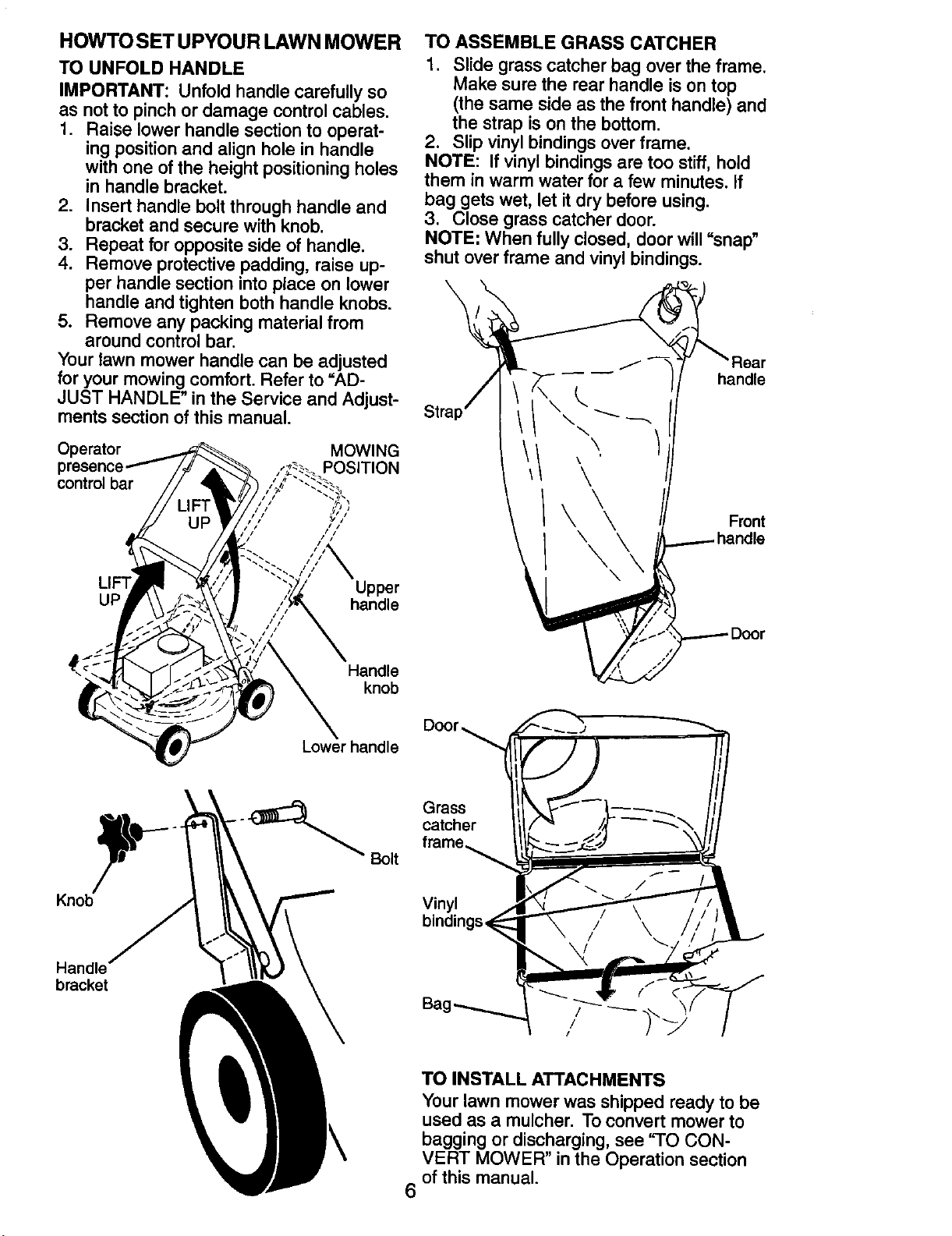
HOWTO SET UPYOUR LAWN MOWER
TO UNFOLD HANDLE
IMPORTANT: Unfold handle carefully so
as not to pinch or damage control cables.
1. Raise lower handle section to operat-
ing position and align hole in handle
with one of the height positioning holes
in handle bracket.
2. Insert handle bolt through handle and
bracket and secure with knob.
3. Repeat for opposite side of handle.
4. Remove protective padding, raise up-
per handle section into place on lower
handle and tighten both handle knobs.
5. Remove any packing material from
around control bar.
Your lawn mower handle can be adjusted
for your mowing comfort. Refer to =AD-
JUST HANDLE" in the Service and Adjust-
ments section of this manual.
Operator MOWING
POSITION
control bar _,
Upper
UP handle
Handle
knob
TO ASSEMBLE GRASS CATCHER
1. Slide grass catcher bag over the frame.
Make sure the rear handle is on top
(the same side as the front handle) and
the strap is on the bottom.
2. Slip vinyl bindings over frame.
NOTE: If vinyl bindings are too stiff, hold
them in warm water for a few minutes, if
bag gets wet, let it dry before using.
3. Close grass catcher door.
NOTE: When fully closed, door will "snap"
shut over frame and vinyl bindings.
J
\
\
\
\ \
\
\
\
handle
Front
Handle
bracket
Lower handle
_.
Bolt
Grass
catcher
Vinyl
\
6
TO INSTALL ATTACHMENTS
Your lawn mower was shipped ready to be
used as a mulcher. To convert mower to
bagging or discharging, see 'q'O CON-
VERT MOWER" in the Operation section
of this manual.
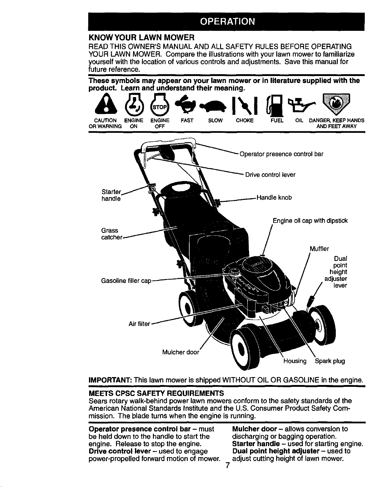
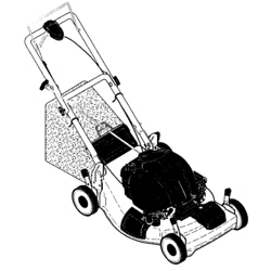
KNOWYOUR LAWN MOWER
READ THIS OWNER'S MANUAL AND ALL SAFETY RULES BEFORE OPERATING
YOUR LAWN MOWER. Compare the illustrationswithyour lawnmowerto familiarize
yourselfwiththe locationof variouscontrolsand adjustments. Save this manualfor
future reference.
These symbols may appear on your lawn mower or in literature supplied with the
product. Learn and understand their meaning.
CAUTION ENGINE ENGINE FAST SLOW CHOKE FUEL OIL DANGER, KEEP HANDS
OR WARNING ON OFF AND FEET AWAY
-Operator presence control bar
Drive control lever
handle knob
Grass
Engine oil cap with dipstick
Gasoline filler cap
Muffler
Dual
point
height
adjuster
lever
Air filter
Mulcher door
Housing Spark plug
IMPORTANT: This lawn mower is shipped WITHOUT OIL OR GASOLINE in the engine.
MEETS CPSC SAFETY REQUIREMENTS
Sears rotary walk-behind power lawn mowers conform to the safety standards of the
American National Standards Institute and the U.S. Consumer Product Safety Com-
mission. The blade turns when the engine is running.
Operator presence control bar - must
be held down to the handle to start the
engine. Release to stop the engine.
Drive control lever - used to engage
power-propelled forward motion of mower.
7
Mulcher door - allows conversion to
discharging or bagging operation.
Starter handle - used for starting engine.
Dual point height adjuster - used to
adjust cutting height of lawn mower.
The operationof anylawn
mower can result in foreign
objects thrown into the
eyes, which can result in
severe eye damage. Always
wear safety glasses or eye shields while
operating your lawn mower or performing
any adjustments or repairs. We recom-
mend a standard safety glasses or wide
vision safety mask worn over spectacles.
HOWTO USEYOUR LAWN MOWER
ENGINE SPEED
The engine speed was set at the factory
for optimum performance. Speed is not
adjustable.
ENGINE ZONE CONTROL
_:_CAUTION: Federal regulations require
an engine control to be installed on this
lawn mower in order to minimize the
risk of blade contact injury. Do not under
any circumstances attempt to defeat the
function of the operator control. The blade
turns when the engine is running.
• Your lawn mower is equipped with an
operator presence control bar which
requires the operator to be positioned
behind the lawn mower handle to start
and operate the lawn mower.
DRIVE CONTROL
• Self-propelling is controlled by hold-
ing the operator presence control bar
down to the handle and pulling the drive
control lever rearward to the handle.
The farther toward the handle the lever
is pulled, the faster the unit will travel.
• Forward motion will stop when either
the operator presence control bar or
drive control lever are released. To stop
forward motion without stopping engine,
release only the drive control lever. Hold
operator presence control bar down
against handle to continue mowing
without self-propelling.
NOTE: If after releasing the drive control
the mower will not roll backwards, push
the mower forward slightly to disengage
drive wheels.
• To keep drive control engaged when
turning corners, push down on the
handle to lift the front wheels off the
ground while turning lawn mower.
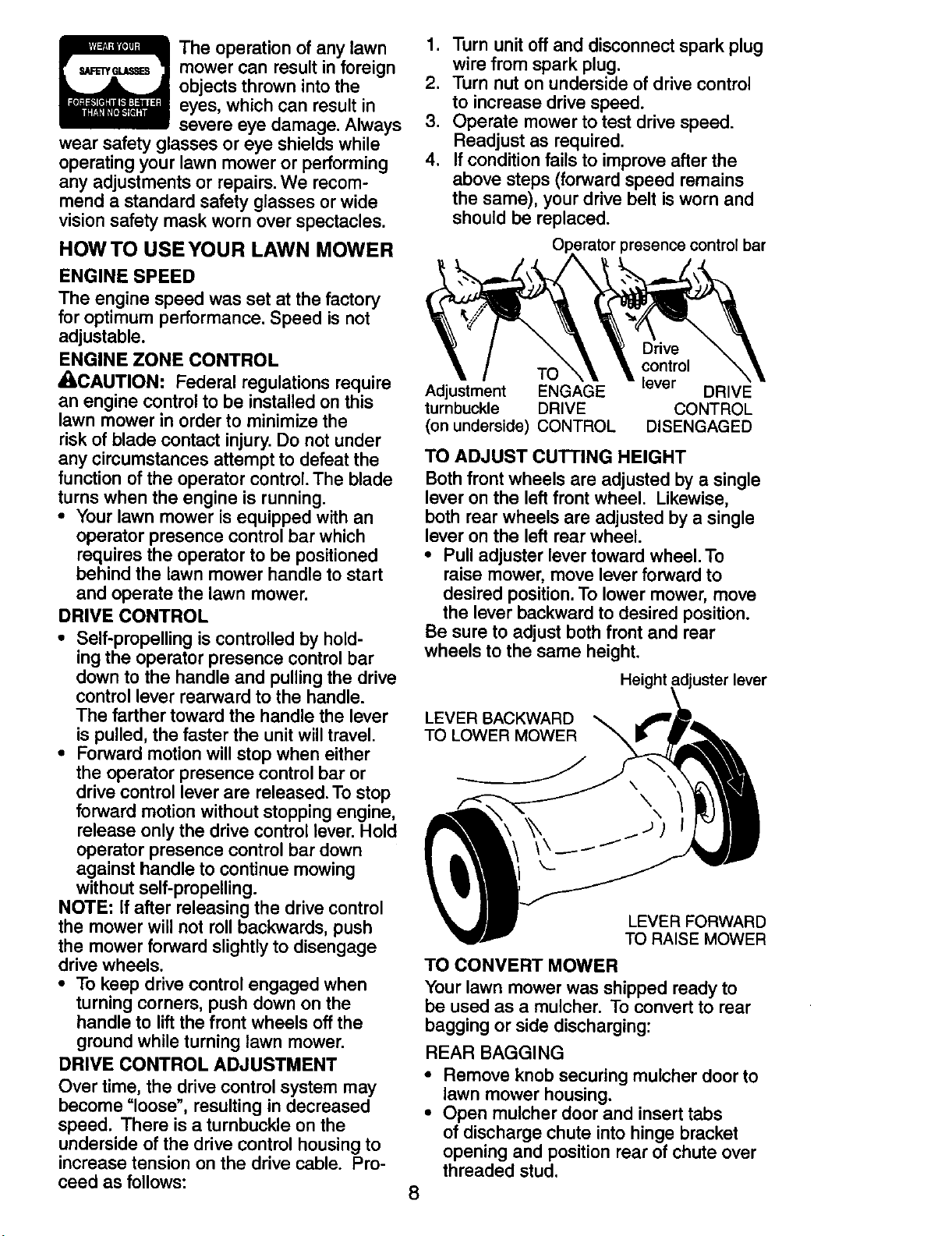
DRIVE CONTROL ADJUSTMENT
Over time, the drive control system may
become "loose", resulting in decreased
speed. There is a turnbuckle on the
underside of the drive control housing to
increase tension on the drive cable. Pro-
ceed as follows:
1. Turn unit off and disconnect spark plug
wire from spark plug.
2. Turn nut on underside of drive control
to increase drive speed.
3. Operate mower to test drive speed.
Readjust as required.
4. If condition fails to improve after the
above steps (forward speed remains
the same), your drive belt is worn and
should be replaced.
presence control bar
Drive
TO control
Adjustment ENGAGE lever DRIVE
turnbuckle DRIVE CONTROL
(on underside) CONTROL DISENGAGED
TO ADJUST CUTTING HEIGHT
Both front wheels are adjusted by a single
lever on the left front wheel. Likewise,
both rear wheels are adjusted by a single
lever on the left rear wheel.
• Pull adjuster lever toward wheel. To
raise mower, move lever forward to
desired position. To lower mower, move
the lever backward to desired position.
Be sure to adjust both front and rear
wheels to the same height.
Height
LEVER BACKWARD
TO LOWER MOWER
LEVER FORWARD
TO RAISE MOWER
TO CONVERT MOWER
Your lawn mower was shipped ready to
be used as a muloher. To convert to rear
bagging or side discharging:
REAR BAGGING
• Remove knob securing mulcher door to
lawn mower housing.
• Open mulcher door and insert tabs
of discharge chute into hinge bracket
opening and position rear of chute over
threaded stud.
8
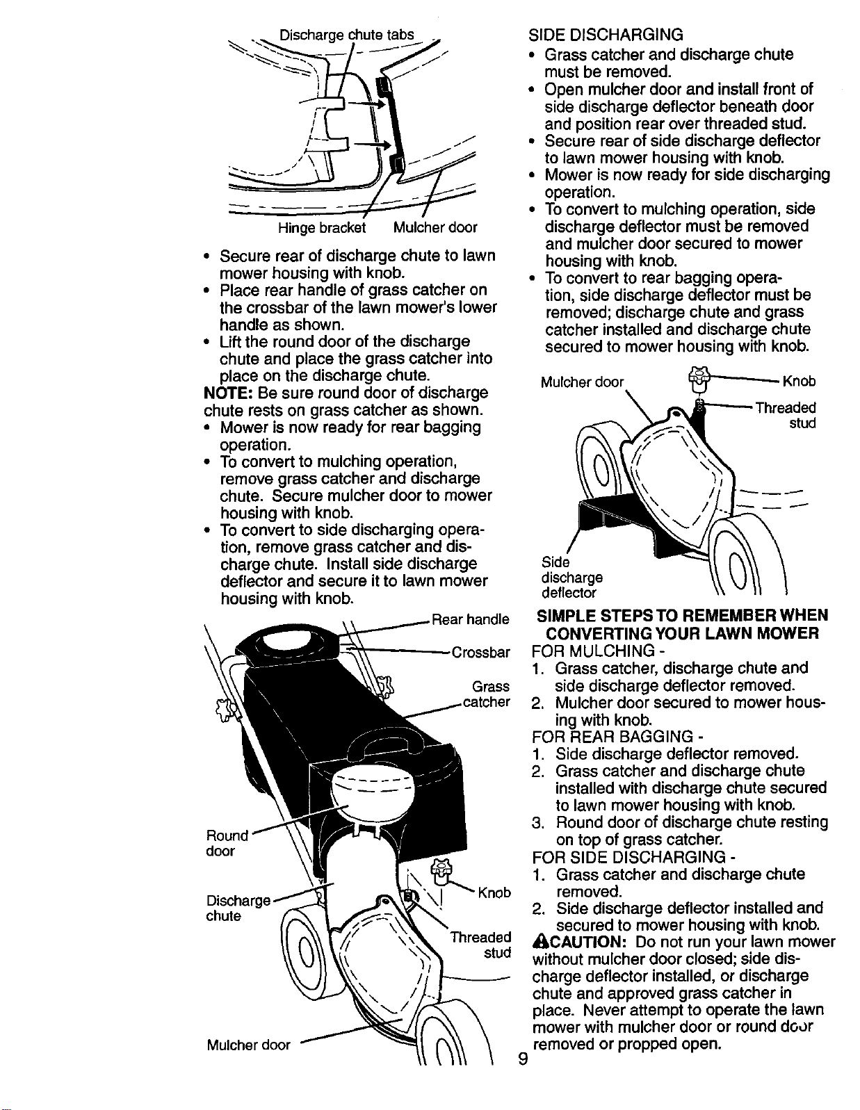
Discharge chute tabs
/
Hinge bracket Mulcher door
• Secure rear of discharge chute to lawn
mower housing with knob.
• Place rear handle of grass catcher on
the crossbar of the lawn mower's lower
handle as shown.
• Lift the round door of the discharge
chute and place the grass catcher into
place on the discharge chute.
NOTE: Be sure round door of discharge
chute rests on grass catcher as shown.
• Mower is now ready for rear bagging
operation.
• To convert to mulching operation,
remove grass catcher and discharge
chute. Secure mulcher door to mower
housing with knob.
• To convert to side discharging opera-
tion, remove grass catcher and dis-
charge chute. Install side discharge
deflector and secure it to lawn mower
housing with knob.
Crossbar
Grass
door
chute
Threaded
stud
Mulcher door
SIDE DISCHARGING
• Grass catcher and discharge chute
must be removed.
• Open mulcher door and install front of
side discharge deflector beneath door
and position rear over threaded stud.
• Secure rear of side discharge deflector
to lawn mower housing with knob.
• Mower is now ready for side discharging
operation.
• To convert to mulching operation, side
discharge deflector must be removed
and mulcher door secured to mower
housing with knob.
• To convert to rear bagging opera-
tion, side discharge deflector must be
removed; discharge chute and grass
catcher installed and discharge chute
secured to mower housing with knob.
Mulcher door Knob
stud
Side
discharge
deflector
SIMPLE STEPS TO REMEMBER WHEN
CONVERTING YOUR LAWN MOWER
FOR MULCHING -
1. Grass catcher, discharge chute and
side discharge deflector removed.
2. Mulcher door secured to mower hous-
ing with knob.
FOR REAR BAGGING -
1. Side discharge deflector removed.
2. Grass catcher and discharge chute
installed with discharge chute secured
to lawn mower housing with knob.
3. Round door of discharge chute resting
on top of grass catcher.
FOR SIDE DISCHARGING -
1. Grass catcher and discharge chute
removed.
2. Side discharge deflector installed and
secured to mower housing with knob.
A, CAUTION: Do not run your lawn mower
without mulcher door closed; side dis-
charge deflector installed, or discharge
chute and approved grass catcher in
place. Never attempt to operate the lawn
mower with mulcher door or round door
removed or propped open.
9
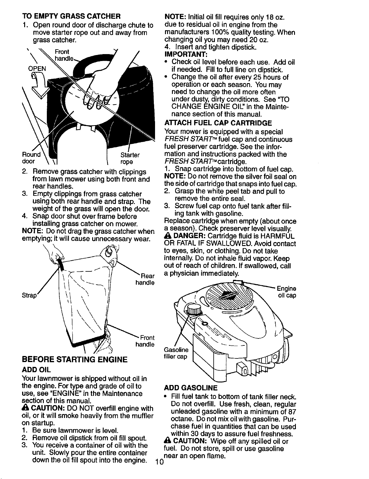
TO EMPTY GRASS CATCHER
1. Open round door of discharge chute to
move starter rope out and away from
grass catcher.
_ Front
OPEN
Round Starter
door rope
2. Remove grass catcher with clippings
from lawn mower using both front and
rear handles.
3. Empty clippings from grass catcher
using both rear handle and strap. The
weight of the grass will open the door.
4. Snap door shut over frame before
installing grass catcher on mower.
NOTE: Do not drag the grass catcher when
emptying; it will cause unnecessary wear.
handle
NOTE: Initial oil fill requires only 18 oz.
due to residual oil in engine from the
manufacturers 100% quality testing. When
changing oil you may need 20 oz.
4. Insert and tighten dipstick.
IMPORTANT:
• Check oil level before each use. Add oil
if needed. Fill to full line on dipstick.
• Change the oil after every 25 hours of
operation or each season. You may
need to change the oil more often
under dusty, dirty conditions. See "TO
CHANGE ENGINE OIL" in the Mainte-
nance section of this manual.
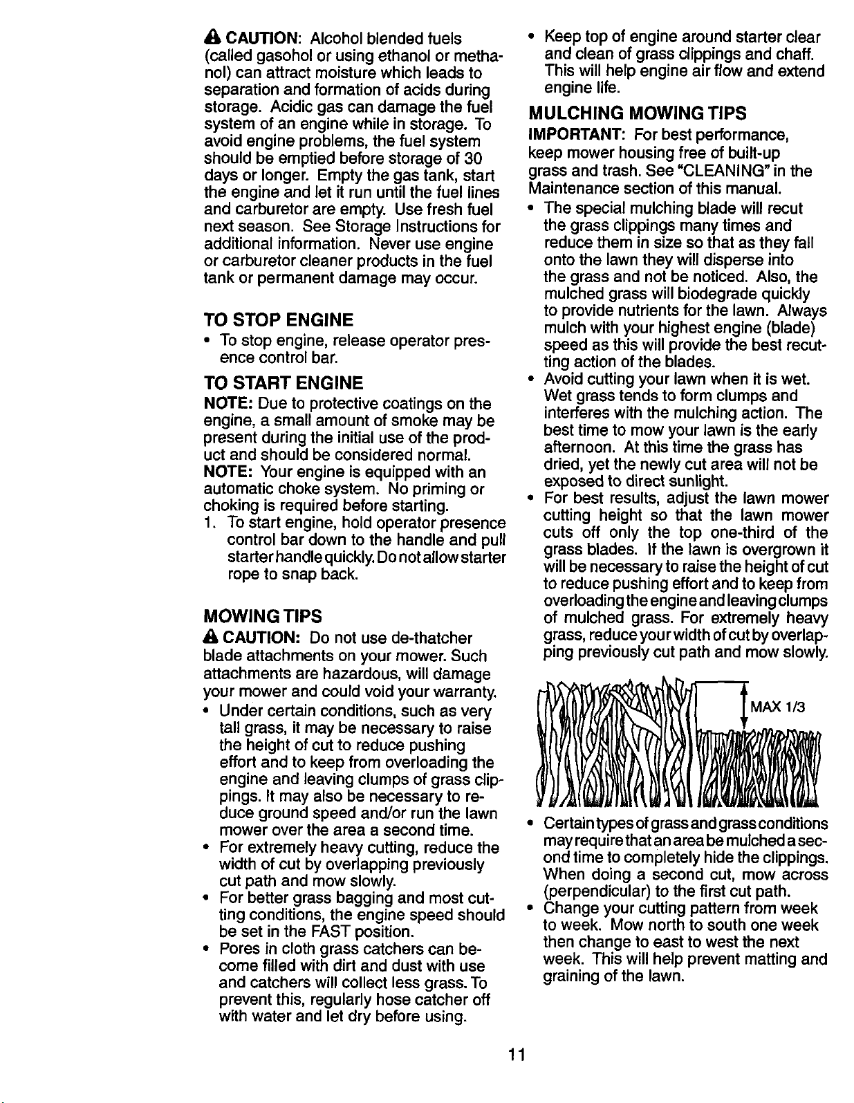
ATFACH FUEL CAP CARTRIDGE
Your mower is equipped with a special
FRESH START TM fuel cap and continuous
fuel preserver cartridge. See the infor-
mation and instructions packed with the
FRESH START'cartridge.
1. Snap cartridge into bottom of fuel cap.
NOTE: Do not remove the silver foil seal on
the side of cartridge that snaps intofuel cap.
2. Grasp the white peel tab and pull to
remove the entire seal.
3. Screw fuel cap onto fuel tank after fill-
ing tank with gasoline.
Replace cartridge when empty (about once
a season). Check preserver level visually.
A DANGER: Cartridge fluid is HARMFUL
OR FATAL IF SWALLOWED. Avoid contact
to eyes, skin, or clothing. Do not take
internally. Do not inhale fluid vapor. Keep
out of reach of children. If swallowed, call
a physician immediately.
Engine
oil cap
\
Front
handle
BEFORE STARTING ENGINE
ADD OIL
Your lawnmower is shipped without oil in
the engine. For type and grade of oil to
use, see "ENGINE" in the Maintenance
section of this manual.
4_ CAUTION: DO NOT overfill engine with
oil, or itwill smoke heavily from the muffler
on startup.
1. Be sure lawnmower is level.
2. Remove oil dipstick from oil fill spout.
3. You receive a container of oil with the
unit. Slowly pour the entire container
down the oil fill spout into the engine.
Gasoline
filler cap
ADD GASOLINE
• Fill fuel tank to bottom of tank filler neck.
Do not overfill. Use fresh, clean, regular
unleaded gasoline with a minimum of 87
octane. Do not mix oil with gasoline. Pur-
chase fuel in quantities that can be used
within 30 days to assure fuel freshness.
A CAUTION: Wipe off any spilled oil or
fuel. Do not store, spill or use gasoline
near an open flame.
10
CAUTION: Alcoholblended fuels
(called gasohol or using ethanol or metha-
nol) can attract moisture which leads to
separation and formation of acids during
storage. Acidic gas can damage the fuel
system of an engine while in storage. To
avoid engine problems, the fuel system
should be emptied before storage of 30
days or longer. Empty the gas tank, start
the engine and let it run until the fuel lines
and carburetor are empty. Use fresh fuel
next season. See Storage Instructions for
additional information. Never use engine
or carburetor cleaner products in the fuel
tank or permanent damage may occur.
TO STOP ENGINE
• To stop engine, release operator pres-
ence control bar.
TO START ENGINE
NOTE: Due to protective coatings on the
engine, a small amount of smoke may be
present during the initial use of the prod-
uct and should be considered normal.
NOTE: Your engine is equipped with an
automatic choke system. No priming or
choking is required before starting.
1. To start engine, hold operator presence
control bar down to the handle and pull
starter handle quickly.Do not allow starter
rope to snap back.
MOWING TIPS
A CAUTION: Do not use de-thatcher
blade attachments on your mower. Such
attachments are hazardous, will damage
your mower and could void your warranty.
• Under certain conditions, such as very
tall grass, it may be necessary to raise
the height of cut to reduce pushing
effort and to keep from overloading the
engine and leaving clumps of grass clip-
pings. It may also be necessary to re-
duce ground speed and/or run the lawn
mower over the area a second time.
• For extremely heavy cutting, reduce the
width of cut by overlapping previously
cut path and mow slowly.
• For better grass bagging and most cut-
ting conditions, the engine speed should
be set in the FAST position.
• Pores in cloth grass catchers can be-
come filled with dirt and dust with use
and catchers will collect less grass. To
prevent this, regularly hose catcher off
with water and let dry before using.
• Keep top of engine around starter clear
and clean of grass clippings and chaff.
This will help engine air flow and extend
engine life.
MULCHING MOWING TIPS
IMPORTANT: For best performance,
keep mower housing free of built-up
grass and trash. See =CLEANING _in the
Maintenance section of this manual.
• The special mulching blade will recut
the grass clippings many times and
reduce them in size so that as they fall
onto the lawn they will disperse into
the grass and not be noticed. Also, the
mulched grass will biodegrade quickly
to provide nutrients for the lawn. Always
mulch with your highest engine (blade)
speed as this will provide the best recut-
ting action of the blades.
• Avoid cutting your lawn when it is wet.
Wet grass tends to form clumps and
interferes with the mulching action. The
best time to mow your lawn is the early
afternoon. At this time the grass has
dried, yet the newly cut area will not be
exposed to direct sunlight.
• For best results, adjust the lawn mower
cutting height so that the lawn mower
cuts off only the top one-third of the
grass blades. If the lawn is overgrown it
will be necessary to raise the height of cut
to reduce pushing effort and to keep from
overloading the engine and leaving clumps
of mulched grass. For extremely heavy
grass, reduce you rwidth of cut by overlap-
ping previously cut path and mow slowly.
1/3
• Certain types ofgrass and grass conditions
may require that an area be mulched a sec-
ond time to completely hide the clippings.
When doing a second cut, mow across
(perpendicular) to the first cut path.
• Change your cutting pattern from week
to week. Mow north to south one week
then change to east to west the next
week. This will help prevent matting and
graining of the lawn.
11
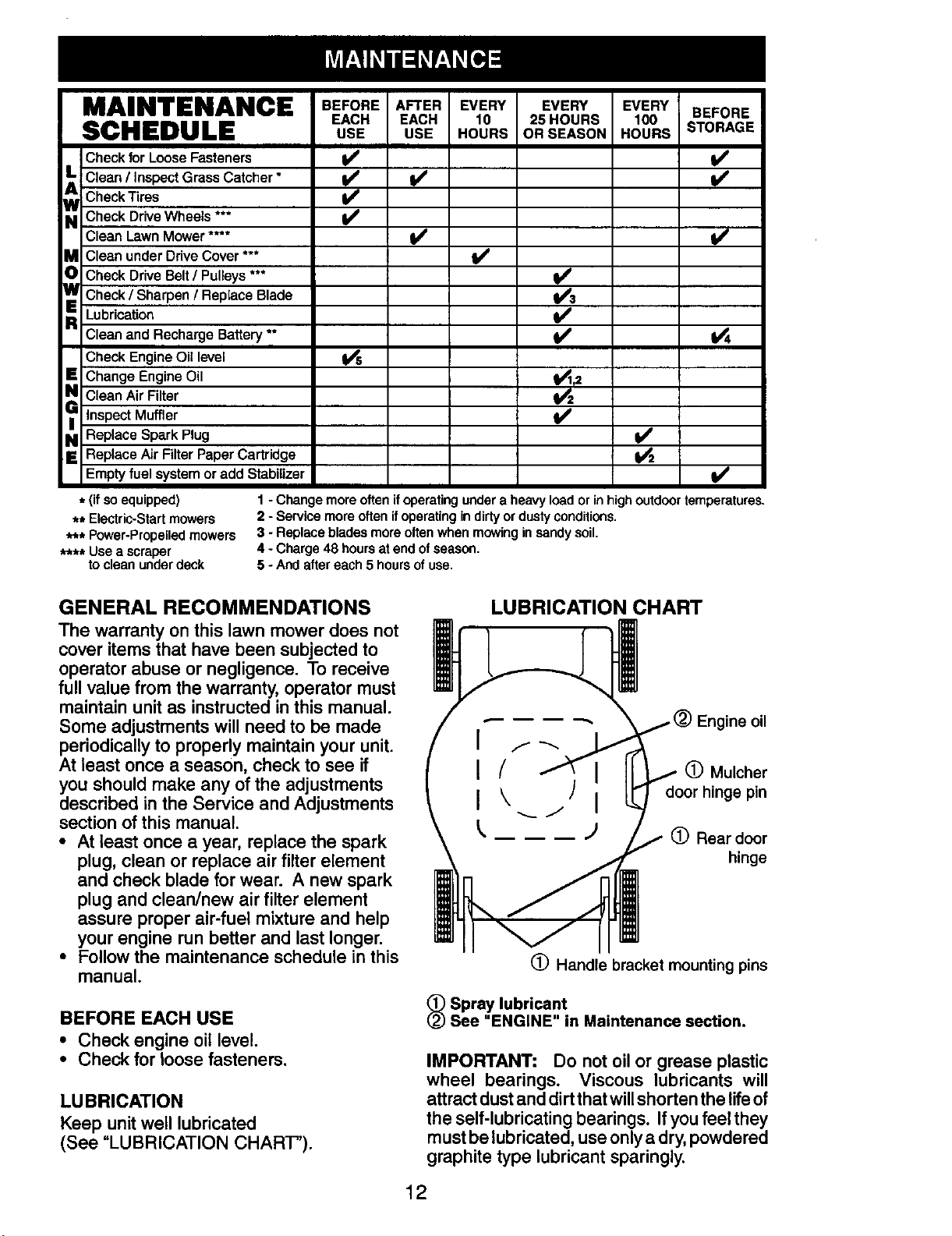
MAINTENANCE BEFORE AFTER EVERY EVERY EVERY BEFORE
EACH EACH 10 25 HOURS 100 STORAGE
SCHEDULE USE USE .OURSORSEASOHHOURS
Check for Loose Fasteners _ I/'
L Clean / Inspect Grass Catcher * I_
Check Tires i_#
_ Check Drive Wheels ***
Clean LawnMower.... ¥/ l#/
_ Clean underDriveCover *** I_
Check Drive Belt / Pulleys ***
_ Check / Sharpen / Replace Blade
R Lubrication
Clean andRecharge Battery ** _ I_
Check Engine Oil level I_
_1 Change Engine Oil _,2
Clean Air Filter
GI Inspect Muffler
Replace Spark Plug ¥1
_ Replace Air Filter Paper Cartridge I_
Empty fuel system or add Stabilizer I/
* (if so equipped)
** Electric-Startmowers
*** Power-Propelledmowers
**** Use a scraper
to clean under deck
1 - Change more often ifoperating under a heavy load or in high outdoortemperatures.
2 - Service more otten ifoperating in dirtyor dusty conditions.
3 - Replace blades more oftenwhen mowing insandy soil.
4 - Charge 48 hours at end ofseason.
5 - And after each 5 hours of use.
GENERAL RECOMMENDATIONS
The warranty on this lawn mower does not
cover items that have been subjected to
operator abuse or negligence. To receive
full value from the warranty, operator must
maintain unit as instructed in this manual.
Some adjustments will need to be made
periodically to properly maintain your unit.
At least once a season, check to see if
you should make any of the adjustments
described in the Service and Adjustments
section of this manual.
• At least once a year, replace the spark
plug, clean or replace air filter element
and check blade for wear. A new spark
plug and clean/new air filter element
assure proper air-fuel mixture and help
your engine run better and last longer.
• Follow the maintenance schedule in this
manual.
BEFORE EACH USE
• Check engine oil level.
• Check for toose fasteners.
LUBRICATION
Keep unit well lubricated
(See "LUBRICATION CHART").
LUBRICATION CHART
(_) Mulcher
door hinge pin
(_ Rear door
hinge
(_ Handle bracket mounting pins
_ Spray lubricant
See "ENGINE" in Maintenance section.
IMPORTANT: Do not oil or grease plastic
wheel bearings. Viscous lubricants will
attract dust and dirt thatwillshorten the lifeof
the self-lubricating bearings. If you feel they
must be lubricated, use only a dry,powdered
graphite type lubricant sparingly.
12
LAWN MOWER
Always observe safety rules when per-
forming any maintenance.
TIRES
• Keep tires free of gasoline, oil, or insect
control chemicals which can harm rubber.
• Avoid stumps, stones, deep ruts, sharp
objects and other hazards that may
cause tire damage.
DRIVE WHEELS
Check rear drive wheels each time you
mow to be sure they move freely. The
wheels not turning freely means trash,
grass cuttings, etc., may be inside the
drive wheel and dust cover area and must
be cleaned out to free drive wheels.
BLADE CARE
For best results, mower blade must be kept
_arp. Replace a bent or damaged blade.
CAUTION: Use only a replacement
blade approved by the manufacturer of
your mower. Using a blade not approved
by the manufacturer of your mower is
hazardous, could damage your mower and
void your warranty.
TO REMOVE BLADE
1. Disconnect spark plug wire from spark
plug and place wire where it cannot
come in contact with plug.
2. Turn lawn mower on its side. Make
sure air filter and carburetor are up.
3. Use a wood block between blade and
mower housing to prevent blade from
turning when removing blade bolt.
NOTE: Protect your hands with gloves
and/or wrap blade with heavy cloth.
4. Remove blade bolt by turning counter-
clockwise.
5. Remove blade and attaching hardware
(bolt, lock washer, hardened washer).
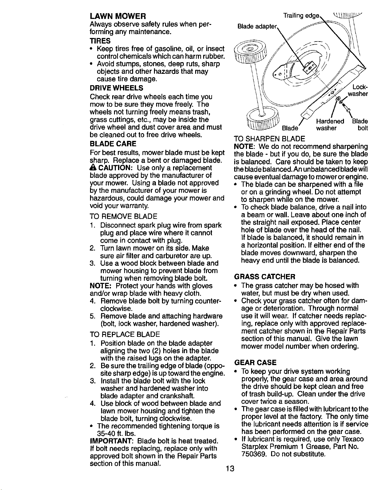
TO REPLACE BLADE
1. Position blade on the blade adapter
aligning the two (2) holes in the blade
with the raised lugs on the adapter.
2. Be sure the trailing edge of blade (oppo-
site sharp edge) is up toward the engine.
3. Install the blade bolt with the lock
washer and hardened washer into
blade adapter and crankshaft.
4. Use block of wood between blade and
lawn mower housing and tighten the
blade bolt, turning clockwise.
• The recommended tightening torque is
35-40 ft. Ibs.
IMPORTANT: Blade bolt is heat treated.
If bolt needs replacing, replace only with
approved bolt shown in the Repair Parts
section of this manual.
Trailing edge,
Blade
13
Lock-
washer
Hardened Blade
Blade washer bolt
TO SHARPEN BLADE
NOTE: We do not recommend sharpening
the blade - but if you do, be sure the blade
is balanced. Care should be taken to keep
the blade balanced. An unbalanced blade will
cause eventual damage to mower or engine.
• The blade can be sharpened with a file
or on a grinding wheel. Do not attempt
to sharpen while on the mower.
• To check blade balance, drive a nail into
a beam or wall. Leave about one inch of
the straight nail exposed. Place center
hole of blade over the head of the nail.
If blade is balanced, it should remain in
a horizontal position. If either end of the
blade moves downward, sharpen the
heavy end until the blade is balanced.
GRASS CATCHER
• The grass catcher may be hosed with
water, but must be dry when used.
• Check your grass catcher often for dam-
age or deterioration. Through normal
use it will wear. If catcher needs replac-
ing, replace only with approved replace-
ment catcher shown in the Repair Parts
section of this manual. Give the lawn
mower model number when ordering.
GEAR CASE
• To keep your drive system working
properly, the gear case and area around
the drive should be kept clean and free
of trash build-up. Clean under the drive
cover twice a season.
• The gear case isfilled with lubricant to the
proper level at the factory. The only time
the lubricant needs attention is if service
has been performed on the gear case.
• If lubricant is required, use only Texaco
Starplex Premium 1 Grease, Part No.
750369. Do not substitute,
ENGINE
LUBRICATION
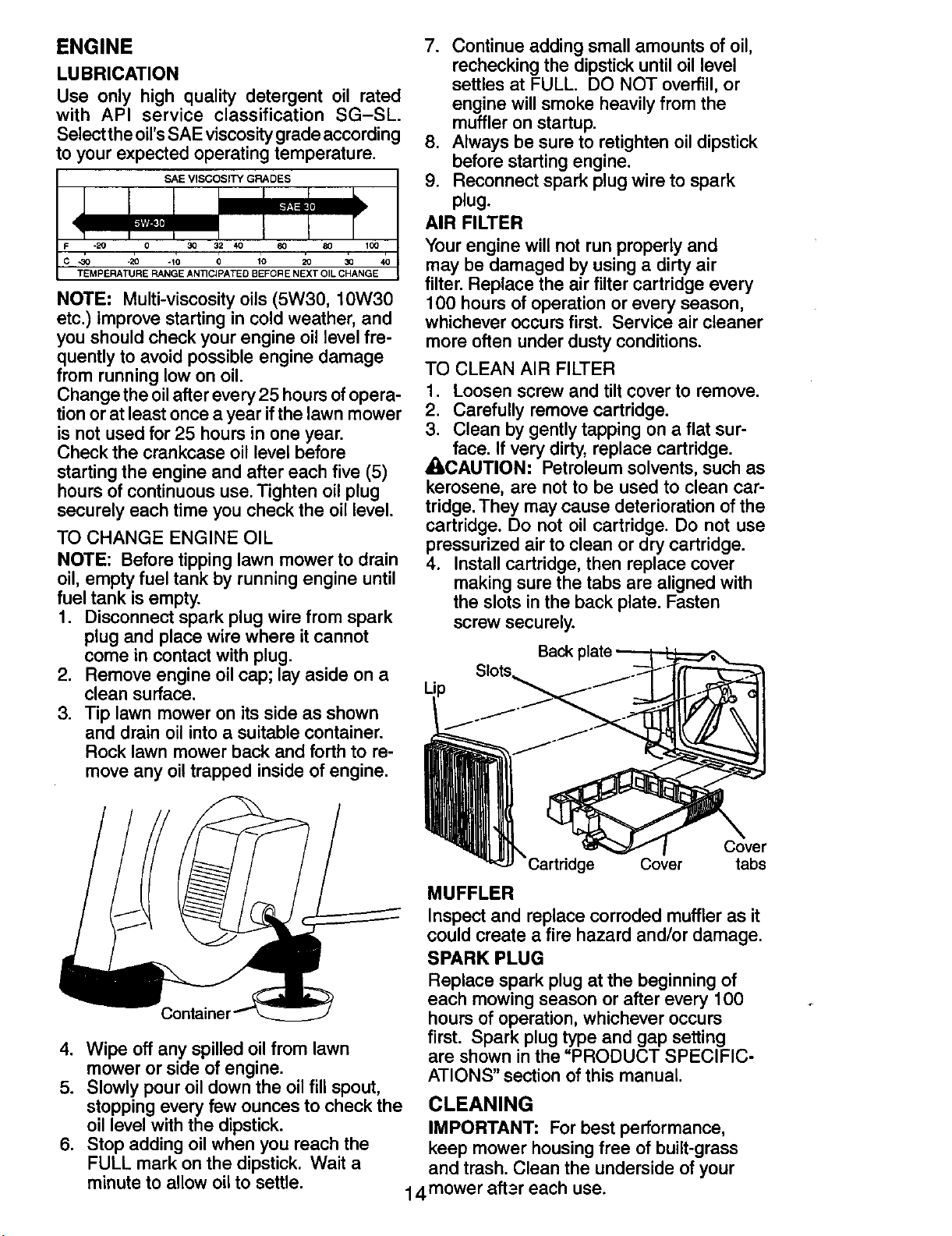
Use only high quality detergent oil rated
with API service classification SG-SL.
Select the oil's SAE viscosity grade according
to your expected operating temperature.
SAE VISCOSITY GRADES
C -30 -20 -10 0 10 20 30 40
TEMPERATURE RANGE ANTICIPATED BEFGR E NEXT OIL CHANGE
NOTE: Multi-viscosity oils (5W30, 10W30
etc.) improve starting in cold weather, and
you should check your engine oil level fre-
quently to avoid possible engine damage
from running low on oil.
Change the oilafter every 25 hours of opera-
tion or at least once a year if the lawn mower
is not used for 25 hours in one year.
Check the crankcase oil level before
starting the engine and after each five (5)
hours of continuous use. Tighten oil plug
securely each time you check the oil level.
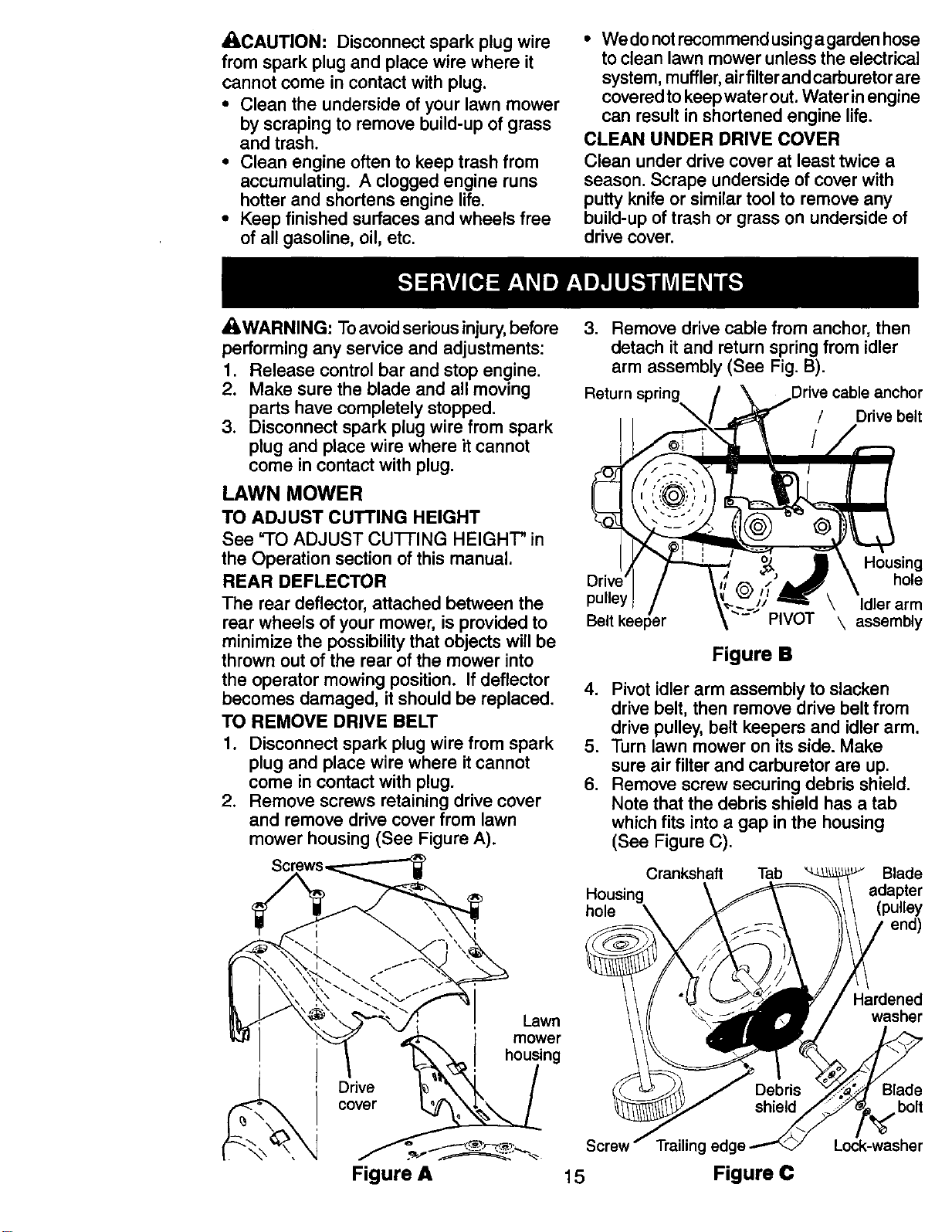
TO CHANGE ENGINE OIL
NOTE: Before tipping lawn mower to drain
oil, empty fuel tank by running engine until
fuel tank is empty.
1. Disconnect spark plug wire from spark
plug and place wire where it cannot
come in contact with plug.
2. Remove engine oil cap; lay aside on a
clean surface.
3. Tip lawn mower on its side as shown
and drain oil into a suitable container.
Rock lawn mower back and forth to re-
move any oil trapped inside of engine.
7. Continue adding small amounts of oil,
rechecking the dipstick until oil level
settles at FULL. DO NOT overfill, or
engine will smoke heavily from the
muffler on startup.
8. Always be sure to retighten oil dipstick
before starting engine.
9. Reconnect spark plug wire to spark
plug.
AIR FILTER
Your engine will not run properly and
may be damaged by using a dirty air
filter. Replace the air filter cartridge every
100 hours of operation or every season,
whichever occurs first. Service air cleaner
more often under dusty conditions.
TO CLEAN AIR FILTER
1. Loosen screw and tilt cover to remove.
2. Carefully remove cartridge.
3. Clean by gently tapping on a flat sur-
face. If very dirty, replace cartridge.
AOAUTION: Petroleum solvents, such as
kerosene, are not to be used to clean car-
tridge. They may cause deterioration of the
cartridge. Do not oil cartridge. Do not use
pressurized air to clean or dry cartridge.
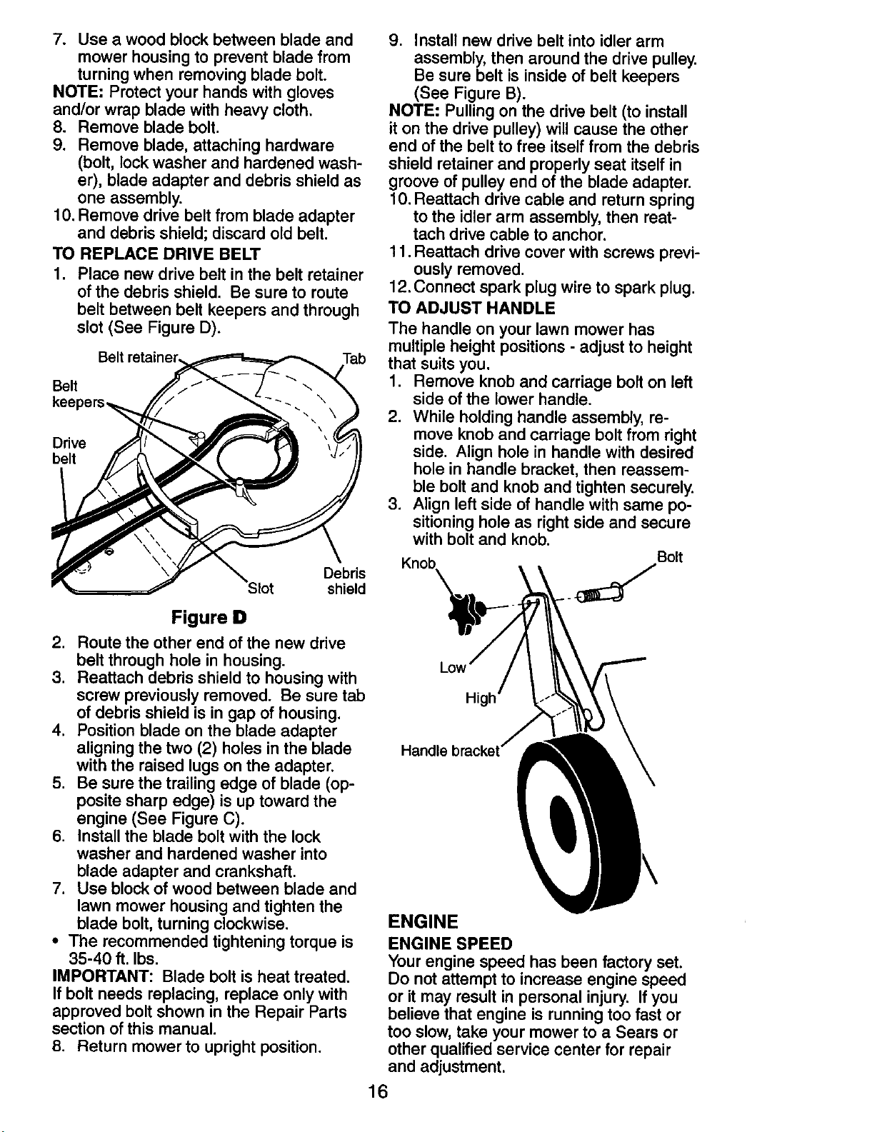
4. Install cartridge, then replace cover
making sure the tabs are aligned with
the slots in the back plate. Fasten
screw securely.
Back
Cover
Cover tabs
4. Wipe off any spilled oil from lawn
mower or side of engine.
5. Slowly pour oil down the oil fill spout,
stopping every few ounces to check the
oil level with the dipstick.
6. Stop adding oil when you reach the
FULL mark on the dipstick. Wait a
MUFFLER
Inspect and replace corroded muffler as it
could create a fire hazard and/or damage.
SPARK PLUG
Replace spark plug at the beginning of
each mowing season or after every 100
hours of operation, whichever occurs
first. Spark plug type and gap setting
are shown in the "PRODUCT SPECIFIC-
ATIONS" section of this manual.
CLEANING
minute to allow oil to settle.
IMPORTANT: For best performance,
keep mower housing free of built-grass
and trash. Clean the underside of your
14 m°wer aft3r each use.
,ACAUTION- Disconnect spark plug wire
from spark plug and place wire where it
cannot come in contact with plug.
• Clean the underside of your lawn mower
by scraping to remove build-up of grass
and trash.
• Clean engine often to keep trash from
accumulating. A clogged engine runs
hotter and shortens engine life.
• Keep finished surfaces and wheels free
of all gasoline, oil, etc.
• We do not recommend using agarden hose
to clean lawn mower unless the electrical
system, muffler,airfilter and carburetor are
covered to keep water out. Water inengine
can result in shortened engine life.
CLEAN UNDER DRIVE COVER
Clean under drive cover at least twice a
season. Scrape underside of cover with
putty knife or similar tool to remove any
build-up of trash or grass on underside of
drive cover.
A, WARNING: To avoid serious injury, before
performing any service and adjustments:
1. Release control bar and stop engine.
2. Make sure the blade and all moving
parts have completely stopped.
3. Disconnect spark plug wire from spark
plug and place wire where it cannot
come in contact with plug.
LAWN MOWER
TO ADJUST CUTTING HEIGHT
See "TO ADJUST CU'I-rlNG HEIGHT" in
the Operation section of this manual.
REAR DEFLECTOR
The rear deflector, attached between the
rear wheels of your mower, is provided to
minimize the possibility that objects will be
thrown out of the rear of the mower into
the operator mowing position. If deflector
becomes damaged, it should be replaced.
TO REMOVE DRIVE BELT
1. Disconnect spark plug wire from spark
plug and place wire where it cannot
come in contact with plug.
2. Remove screws retaining drive cover
and remove drive cover from lawn
mower housing (See Figure A).
Drive
cover
Lawn
mower
housing
3. Remove drive cable from anchor, then
detach it and return spring from idler
arm assembly (See Fig. B).
Return cable anchor
/ Drive belt
Housing
hole
pulley Idler arm
Belt keeper PIVOT \ assembly
Figure B
4. Pivot idler arm assembly to slacken
drive belt, then remove drive belt from
drive pulley, belt keepers and idler arm.
5. Turn lawn mower on its side. Make
sure air filter and carburetor are up.
6. Remove screw securing debris shield.
Note that the debris shield has a tab
which fits into a gap in the housing
(See Figure C).
Crankshaft Tab Blade
Housing adapter
hole (pulley
end)
Hardened
washer
3lade
bolt
Lock-washer
g edg,
Figure A 15 Figure C
7. Use a wood block between blade and
mower housing to prevent blade from
turning when removing blade bolt.
NOTE; Protect your hands with gloves
and/or wrap blade with heavy cloth.
8. Remove blade bolt.
9. Remove blade, attaching hardware
(bolt, lock washer and hardened wash-
er), blade adapter and debris shield as
one assembly.
10. Remove drive belt from blade adapter
and debris shield; discard old belt.
TO REPLACE DRIVE BELT
1. Place new drive belt in the belt retainer
of the debris shield. Be sure to route
belt between belt keepers and through
slot (See Figure D).
Belt
Tab
Belt
Drive
belt
Debris
Slot shield
9. Install new drive belt into idler arm
assembly, then around the drive pulley.
Be sure belt is inside of belt keepers
(See Figure B).
NOTE= Pulling on the drive belt (to install
it on the drive pulley) will cause the other
end of the belt to free itself from the debris
shield retainer and properly seat itself in
groove of pulley end of the blade adapter.
10. Reattach drive cable and return spring
to the idler arm assembly, then reat-
tach drive cable to anchor.
11. Reattach drive cover with screws previ-
ously removed.
12. Connect spark plug wire to spark plug.
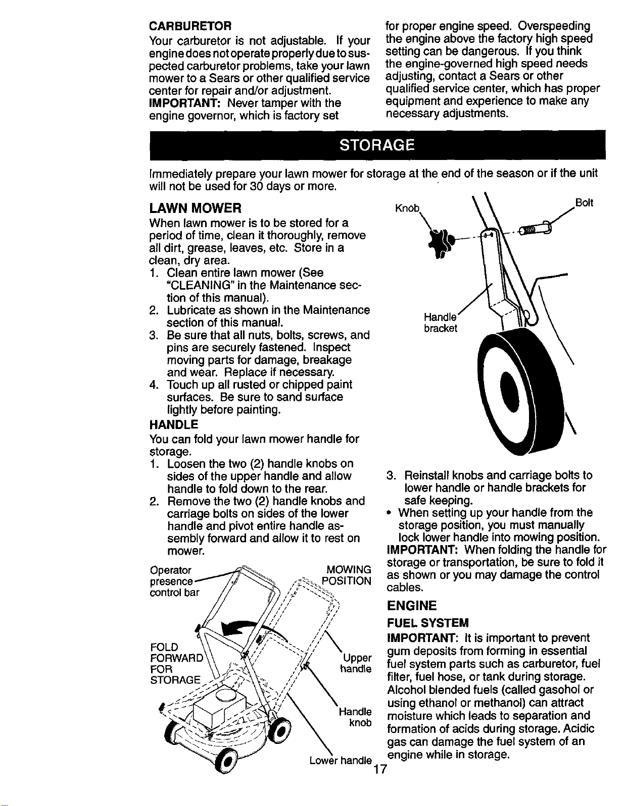
TO ADJUST HANDLE
The handle on your lawn mower has
multiple height positions - adjust to height
that suits you.
1. Remove knob and carriage bolt on left
side of the lower handle.
2. While holding handle assembly, re-
move knob and carriage bolt from right
side. Align hole in handle with desired
hole in handle bracket, then reassem-
ble bolt and knob and tighten securely.
3. Align left side of handle with same po-
sitioning hole as right side and secure
with bolt and knob.
Bolt
Figure D
2. Route the other end of the new drive
belt through hole in housing.
3. Reattach debris shield to housing with
screw previously removed. Be sure tab
of debris shield is in gap of housing.
4. Position blade on the blade adapter
aligning the two (2) holes in the blade
with the raised lugs on the adapter.
5. Be sure the trailing edge of blade (op-
posite sharp edge) is up toward the
engine (See Figure C).
6. Install the blade bolt with the lock
washer and hardened washer into
blade adapter and crankshaft.
7. Use block of wood between blade and
lawn mower housing and tighten the
blade bolt, turning clockwise.
• The recommended tightening torque is
35-40 ft. Ibs.
IMPORTANT: Blade bolt is heat treated.
If bolt needs replacing, replace only with
approved bolt shown in the Repair Parts
section of this manual.
8. Return mower to upright position.
Handle brackel
ENGINE
ENGINE SPEED
Your engine speed has been factory set.
Do not attempt to increase engine speed
or it may result in personal injury. If you
believe that engine is running too fast or
too slow, take your mower to a Sears or
other qualified service center for repair
and adjustment.
16
CARBURETOR
Your carburetor is not adjustable. If your
engine does not operate properly due tosus-
pected carburetor problems, take your lawn
mower to a Sears or other qualified service
center for repair and/or adjustment.
IMPORTANT: Never tamper with the
engine governor, which is factory set
for proper engine speed. Overspeeding
the engine above the factory high speed
setting can be dangerous. If you think
the engine-governed high speed needs
adjusting, contact a Sears or other
qualified service center, which has proper
equipment and experience to make any
necessary adjustments.
Immediately prepare your lawn mower for storage at the end of the season or ifthe unit
will not be used for 30 days or more.
LAWN MOWER
When lawn mower is to be stored for a
period of time, clean it thoroughly, remove
all dirt, grease, leaves, etc. Store ina
clean, dry area.
1. Clean entire lawn mower (See
=CLEANING" in the Maintenance sec-
tion of this manual).
2. Lubricate as shown in the Maintenance
section of this manual.
3. Be sure that all nuts, bolts, screws, and
pins are securely fastened. Inspect
moving parts for damage, breakage
and wear. Replace if necessary.
4. Touch up all rusted or chipped paint
surfaces. Be sure to sand surface
lightly before painting.
HANDLE
You can fold your lawn mower handle for
storage.
1. Loosen the two (2) handle knobs on
sides of the upper handle and allow
handle to fold down to the rear.
2. Remove the two (2) handle knobs and
carriage bolts on sides of the lower
handle and pivot entire handle as-
sembly forward and allow itto rest on
mower.
Operator MOWING
p POSITION
control bar
Knob
Bolt
Handle
bmc_t
3. Reinstall knobs and carriage bolts to
lower handle or handle brackets for
safe keeping.
• When setting up your handle from the
storage position, you must manually
lock lower handle into mowing position.
IMPORTANT" When folding the handle for
storage or transportation, be sure to fold it
as shown or you may damage the control
cables.
ENGINE
FOLD
FORWARD
FOR
Upper
handle
FUEL SYSTEM
IMPORTANT: It is important to prevent
gum deposits from forming in essential
fuel system parts such as carburetor, fuel
filter, fuel hose, or tank during storage.
Alcohol blended fuels (called gasohol or
using ethanol or methanol) can attract
Handle moisture which leads to separation and
knob formation of acids during storage. Acidic
gas can damage the fuel system of an
Lowerhandle engine while in storage.
17
• Empty the fuel tank by starting the en-
gine and letting it run untilthe fuel lines
and carburetor are empty.
• Never use engine or carburetor cleaner
products in the fuel tank or permanent
damage may occur.
• Use fresh fuel next season.
NOTE: Fuel stabilizer is an acceptable
alternative in minimizing the formation of
fuel gum deposits during storage. Add
stabilizer to gasoline in fuel tank or stor-
age container. Always follow the mix ratio
found on stabilizer container. Run engine
at least 10 minutes after adding stabilizer
to allow the stabilizer to reach the car-
buretor. Do not empty the gas tank and
carburetor if using fuel stabilizer.
NOTE: FRESH STAR_ Mfuel cap and
cartridge system automatically drips con-
centrated fuel preserver into your fuel tank
and is an acceptable alternative to adding
fuel stabilizer.
ENGINE OIL
Drain oil (with engine warm) and replace
with clean engine oil. (See "ENGINE" in
the Maintenance section of this manual).
CYLINDER
1. Remove spark plug.
2. Pour one ounce (29 ml) of oil through
spark plug hole into cylinder.
3. Pull starter handle slowly a few times
to distribute oil.
4. Replace with new spark plug.
OTHER
• Do not store gasoline from one season
to another.
• Replace your gasoline can if your can
starts to rust. Rust and/or dirt in your
gasoline will cause problems.
• If possible, store your unit indoors and
cover it to protect it from dust and dirt.
• Cover your unit with a suitable protec-
tive cover that does not retain moisture.
Do not use plastic. Plastic cannot
breathe, which allows condensation to
form and will cause your unit to rust.
IMPORTANT: Never cover mower while
engine and exhaust areas are still warm.
ACAUTION: Never store the lawn mower
with gasoline in the tank inside a building
where fumes may reach an open flame
or spark. Allow the engine to cool before
storing in any enclosure.
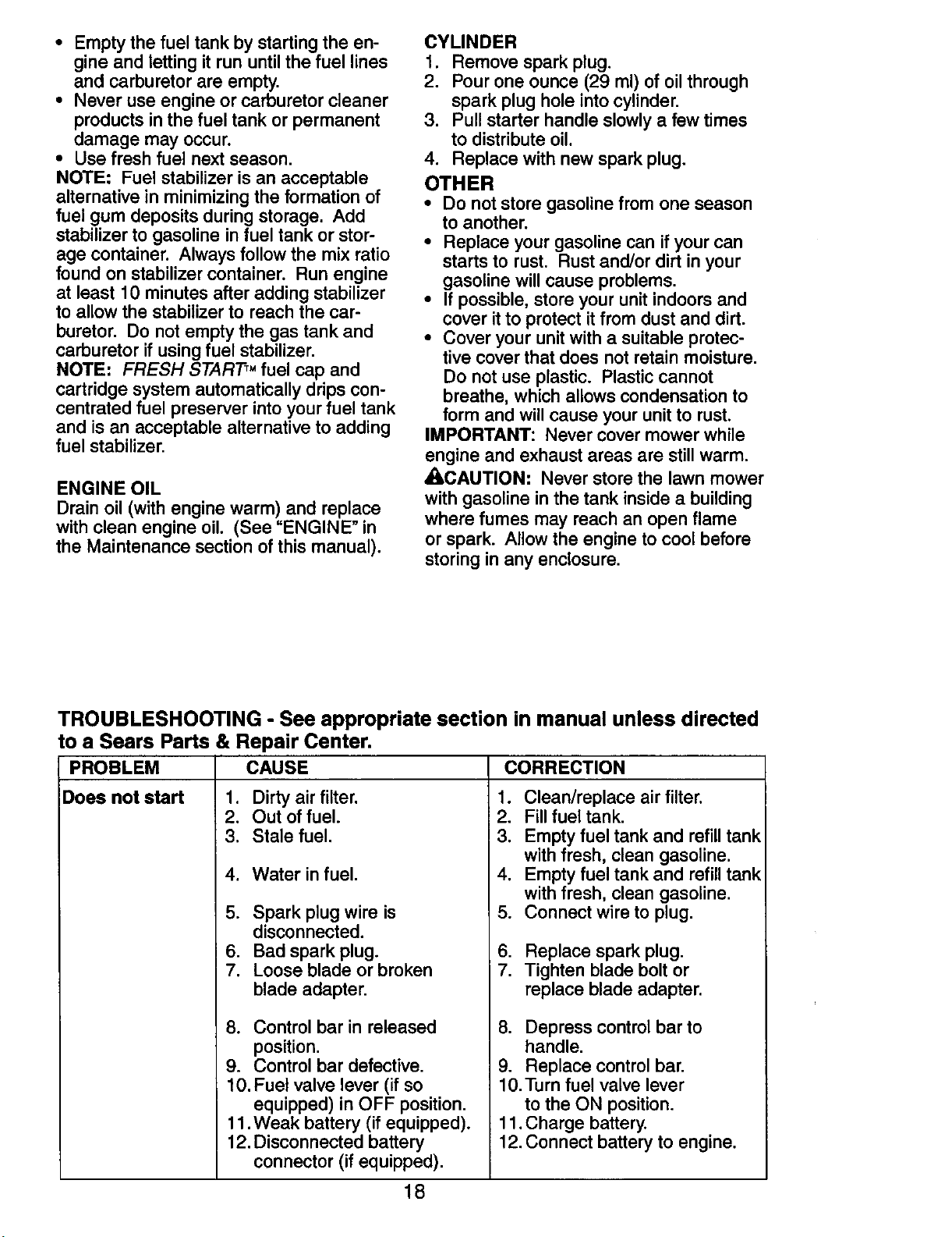
TROUBLESHOOTING - See appropriate section in manual unless directed
to a Sears Parts & Repair Center.
PROBLEM CAUSE CORRECTION
Does not start 1. Dirtyair filter. 1. Clean/replece air filter.
2. Out of fuel.
3. Stale fuel.
4. Water in fuel.
5. Spark plug wire is
disconnected.
6. Bad spark plug.
7. Loose blade or broken
blade adapter.
8. Control bar in released
position.
9. Control bar defective.
10. Fuel valve lever (if so
equipped) in OFF position.
11. Weak battery (if equipped).
12. Disconnected battery
connector (if equipped).
.
3.
4.
5.
6.
7.
Fill fuel tank.
Empty fuel tank and refill tank
with fresh, clean gasoline.
Empty fuel tank and refill tank
with fresh, clean gasoline.
Connect wire to plug.
Replace spark plug.
Tighten blade bolt or
replace blade adapter.
8. Depress control bar to
handle.
9. Replace control bar.
10.Turn fuel valve lever
to the ON position.
11. Charge battery.
12. Connect battery to engine.
18
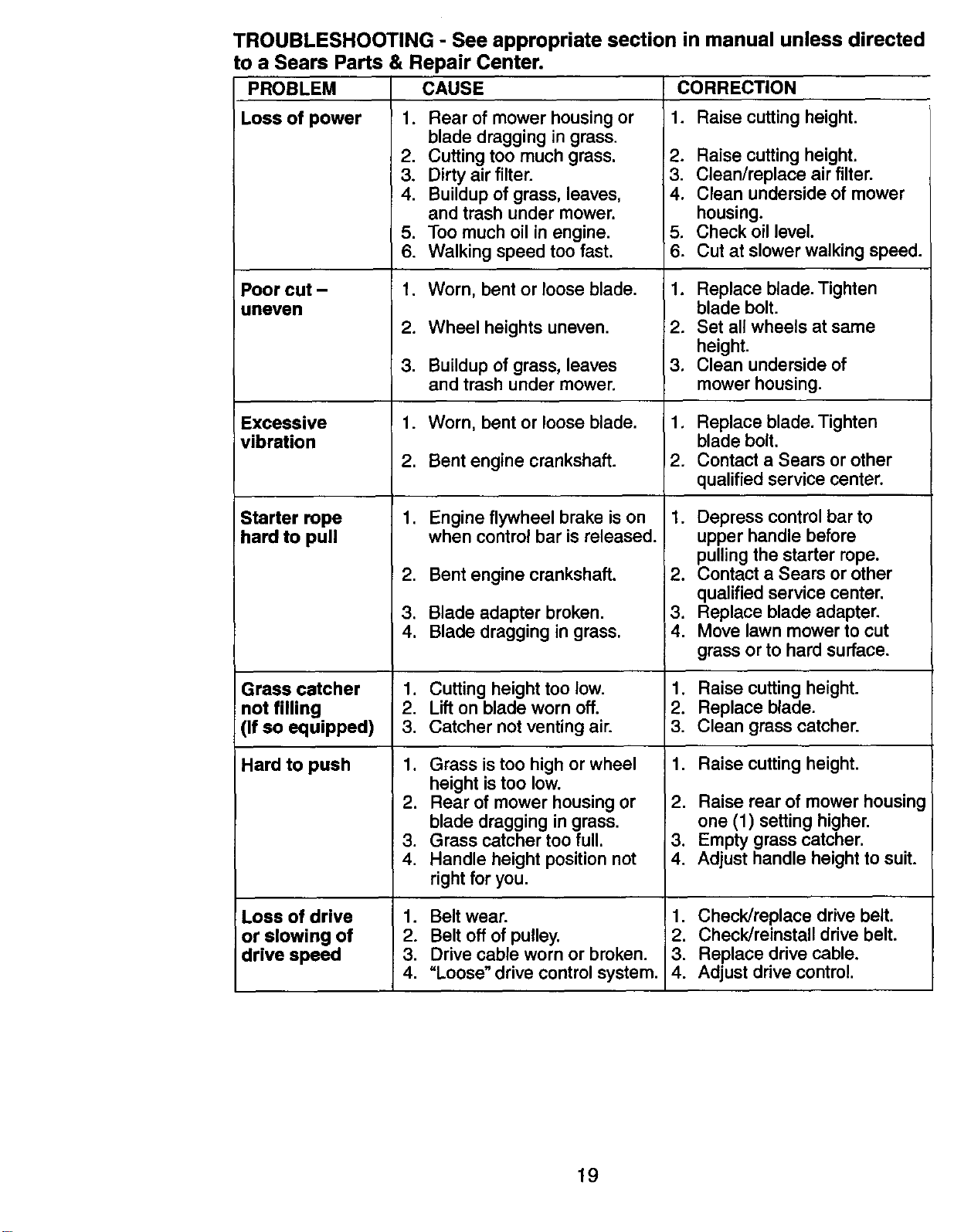
TROUBLESHOOTING - See appropriate section in manual unless directed
to a Sears Parts & Repair Center.
CAUSEPROBLEM
Loss of power
Poor cut -
uneven
Excessive
vibration
Starter rope
hard to pull
1. Rear of mower housing or
blade dragging in grass.
2. Cutting too much grass.
3. Dirty air filter.
4. Buildup of grass, leaves,
and trash under mower.
5. Too much oil in engine.
6. Walking speed too fast.
1. Worn, bent or loose blade.
2. Wheel heights uneven.
3. Buildup of grass, leaves
and trash under mower.
1. Worn, bent or loose blade.
2. Bent engine crankshaft.
.
2.
3.
4.
Engine flywheel brake is on
when control bar is released.
Bent engine crankshaft.
Blade adapter broken.
Blade dragging in grass.
CORRECTION
1. Raise cutting height.
2. Raise cutting height.
3. Clean/replace air filter.
4. Clean underside of mower
housing.
5. Check oil level.
6. Cut at slower walking speed.
1. Replace blade. Tighten
blade bolt.
2. Set all wheels at same
height.
3, Clean underside of
mower housing.
1. Replace blade. Tighten
blade bolt.
2. Contact a Sears or other
qualified service center.
1. Depress control bar to
upper handle before
pulling the starter rope.
2. Contact a Sears or other
qualified service center.
3. Replace blade adapter,
4. Move lawn mower to cut
grass or to hard surface.
Grass catcher 1. Cutting height too low. 1. Raise cutting height.
not filling 2. Lift on blade worn off. 2. Replace blade.
(If so equipped) 3. Catcher not venting air. 3. Clean grass catcher.
Hard to push 1. Raise cutting height.1. Grass is too high or wheel
height is too low.
2. Rear of mower housing or
blade dragging in grass.
3. Grass catcher too full.
4. Handle height position not
right for you.
Loss of drive
or slowing of
drive speed
1. Belt wear.
2. Belt off of pulley.
3. Drive cable worn or broken.
4. "Loose" drive control system.
2. Raise rear of mower housing
one (1) setting higher.
3. Empty grass catcher.
4. Adjust handle height to suit.
1. Check/replace drive belt.
2. Check/reinstall drive belt.
3. Replace drive cable.
4. Adjust drive control.
19
Garantfa ......................................................... 20
Reglas de Seguridad ................................ 20-22
Montaje / Pre-Operaci6n .......................... 23-24
Operaci6n ................................................. 25-29
Mantenimiento .......................................... 30-33
Programa de Mantenimiento ......................... 31
Especificaciones del Producto ....................... 22
Servicio y Adjustes ................................... 33-35
Almacenamiento ....................................... 35-36
IdenUficaci6n de problemas ...................... 36-37
Partes de repuesto .................................. 38-47
Servicio Sears .................................. Contratapa
GARANT(A LIMITADA DE DOS AI_IOS PARA LA SEGADORA A MOTOR CRAFTSMAN
Por dos (2) afios, a partir de la fecha de compra, cuando esta Segadora Craftsman se mantenga,
lubrique y afine seg_n las instrucciones para la operaci6n y el mantenimiento en el manual del
duefio, Sears reparar_ gratis todo defecto en el material y la mano de obra.
Si la Segadora Craftsman se usa para fines comerciales o de arriendo, esta garantfa s61ose aplica
por noventa (90) dfas a partir de la fecha de compra.
Esta Garantfa no cubre:
• Articulos que se desgastan durante el uso normal tales como las cuchillas segadoras rotatorias,
los adaptadores de la cuchilla, las correas, los filtros de aire y las bujfas.
• Reparaciones necesarias debido al abuso o a la negligencia del opersdor, incluyendose a los
cig0efiales doblados y a la falta de mantenimiento del equipo seg_n las instrucciones que se
incluyen en el manual del duefio.
El servicio de garantfa esta disponible al devolver la segadora a motor Craftsman al Centro de
Servicio Sears mas cercano en los Estados Unidos. Esta garantfa se aplica solamente mientras el
producto este en uso en los Estados Unidos.
Esta Garantia le otorga derechos legales especfficos, y puede que tambi_n tenga otros derechos
que varfan de estado a estado.
Sears, Roebuck and Co., D/817WA, Hoffman Estates, IL 60179 USA
IMPORTANTE; Esta maquina cortadaora es capaz de amputar las manos y los manos y los pies y
de lanzar objetos. Si no se observan las instrucciones de seguridad siguientes se pueden producir
lesiones graves o la muerte.
i_Busque este sfmbolo que sefiala las precau-
ciones de seguridad de importancia. Quiere
decir - iiiATENCION!!! i iiESTE ALERTO!!!
_SDEGURIDAD ESTA COMPROMETIDA.
VERTENOIA: Siempra desconecte el alam-
bre de la bujfa y p6ngalo donde no pueda entrar
en contacto con la bujfa, para evitar el arranque
por accidente, durante la preparaci6n, el trans-
_k_)' el ajuste o cuando se hacen reparaciones.
VERTENClA: Los bornes, terminales y
accesorios relativos de la baterfa contienen
plomo o compuestos de plomo, productos
qufmi¢os conocidos en el Estado de California
como causa de c_ncer y defectos al nacimiento
u otros dafios reproductivos. Lavar las manos
_pu_s de manipularlos.
RECAUClON: El tubo de escape del motor,
algunos de sus constituyentes y algunos com-
ponentes del vehfculo contienen o desprenden
productos qufmicos conocidos en el Estado de
California como causa de c&ncer y defectos al
_cimiento u otros dafios reproductivos.
PRECAUClON: El silenciador y otras piezas
del motor Ilegan a sre extremadamente calien-
tes durante la operaci6n y _L_.,I_" l
siguen siendo calientes
despu_s de que el motor
haya parado. Pars evitar
quemaduras severas,
permanezca lejos de estas _reas.
I. OPERAClON
• Antesdeempezar, debefamiliarizarsecomple-
tamente con los controles y el uso correcto de
la maquina. Para esto, debe leer y comprender
todas las instrucciones que aparecen en la ma-
quina yen los manuales de operacibn.
• No ponga las manos o los pies cerca o
debajo de las partes rotatorias. Mant_ngase
siempra lejos de la abertura de la descarga.
• Permita que solamente las personas ra-
sponsables que est_n familiarizadas con las
instrucciones operen la m&quina.
• Despeje ei _rea de objetos tales como piedras,
juguetes, _lambres, huesos, palos, etc. que pu-
eden ser recogidos y lanzados por lascuchillas.
• Asegl3rase que el _rea no se hallen per-
sonas, antes de segar. Pare la m&quina si
20 alguien entra en el &rea.
Iceiterequiera
]ceiteresidual
idad de 100%
.=itepuede
.=didorade aceite.
tee de cada uso.
io. Llene hasta la
}didora de nivel.
25 horas de oper-
la. Puede necesi-
menudo cuando
;aso sucias. Vea
DEL MOTOR" en
,de este manual.
kP6N DEL
,un tap6n del
rvador de carbu-
ISTART TM. V6ase
.=scontenidas en
) del tap6n del
_do de precinto
=ijaen el tap6n
smovible y tirar
:O.
_nte en el
;pubs de Ilenar
t._vacfo (aproxi-
:la). Controlar
'ador,
Jcho es
A. Evitar el
a rapa, No aeirlo
or del fluido.
os nifios. Si ee
I m_dico,
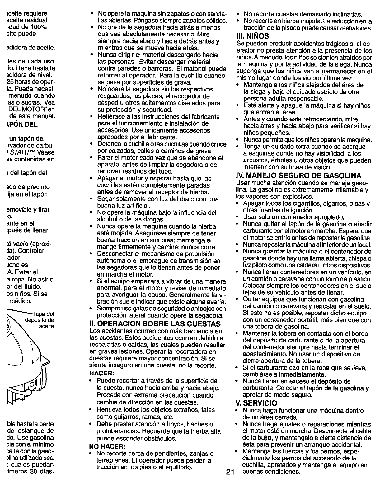
_Tapa del
aceite
ble hasta la parte
del estanque de
rio. Use gasolina
pia con el mfnimo
;eite con la gaso-
)lina utilizada sea
cuales puedan
"imeros 30 dfas.
• No opera la maquina sin zapatos o con sanda-
lias abiertas. P6ngase siempre zapatos .s61idos.
• No tire de la segadora hacia atrds a menos
que sea absolutamente necesario. Mire
siempre hacia abajo y hacia detr_.s antes y
mientras que se mueve hacia atr&s.
• Nunca dirigir el material descargado hacia
las personas. Evitar descargar material
contra parades o barreras. El material puede
retornar al operador. Para la cuchilla cuando
se pasa por superficies de grava.
• No opere la segadora sin los reepectivos
resguardos, las placas, el recogedor de
c6sped u otras aditamentos dise ados para
su protecci6n y seguridad.
• Refi6rase alas instrucciones del fabricante
para el funcionamiento e instalaci6n de
accesorios. Use =3nicamente accesorios
aprobados por el fabricante.
• Detenga la cuchillao las cuchillascuando cruce
por calzadas, calles o caminos de grava.
• Parar el motor cada vez que se abandona el
aparato, antes de limpiar la segadora o de
remover residuos del tubo.
• Apagar el motor y esperar hasta que las
cuchillas est_n completamente paradas
antes de remover el receptor de hierba.
• Segar solamente con luz del dia o con una
buena luz artificial.
• No opera la mdquina bajo la influencia del
alcohol o de las drogas.
• Nunca opera la maquina cuando la hierba
est_ mojada. AsegtJrese siempre de tener
buena tracci6n en sue pies; mantenga el
mango firmemente y camine; nunca corra.
• Desconectar el mecanismo de propulsi6n
aut6noma o el embrague de transmisi6n en
las segadoras que Io tienen antes de poner
en marcha el motor.
• Si el equipo empezara a vibrar de una manera
anormal, pare el motor y revise de inmediato
para averiguar la causa. Generalmente la vi-
braci6n susie indicar que existe alguna averfa.
• Siempra use galas de seguridad o anteojos con
protecci6n lateral cuando opere la segadora.
I1. OPERAClON SOBRE LAS CUESTAS
Los acoidentes ocurren con malefracuencia en
las cuestas. Estos accidentes ocurren debido a
resbaladas o cafdas, las cuales pueden resultar
en graves lesiones. Operar la recortadora en
cuestas requiera mayor concentraci6n. Si se
siente inseguro en una cuesta, no la recorte.
HACER:
• Puede recortar a trav6s de la superficie de
la cuesta, nunca hacia arriba y hacia abajo.
Proceda con extrema precauci6n cuando
cambie de direcci6n en las cuestas.
• Renueva todos los objetos extrafios, tales
como guijarros, ramas, etc.
• Debe prestar atenci6n a hoyos, baches o
protuberancias. Recuerde que la hierba alta
puede esconder obst_iculos.
NO HACER:
• No recorte cerca de pendientes, zanjas o
terraplenes. El operador puede perder la
tracci6n en los pies o el equilibrio.
21
• No recorte cuestas demasiado inclinadas.
• No recorte en hierba mojada. La raducci6n en la
tracci6n de la pisada puede causar resbalones.
III. NINOS
Se pueden producir accidentes trdgicos si el op-
erador no presta atenci6n a la presencia de los
nifios.A menudo, los nifios se sienten atra{dos por
la m_.quina y por la actividad de la siega. Nunca
suponga que los nifios van a permanecer en el
mismo lugar donde los vio por I_ltima vez.
• Mantenga a los nifios alejados del _.rea de
la siega y bajo el cuidado estricto de otra
persona adulta responsable.
• Este alerta y apague la mdquina si hay nifios
que entran al draa.
• Antes y cuando este retrocediendo, mire
hacia atr_is y hacia abajo para verificar si hay
nifios pequefios.
• Nunca permita que los nifios operen la m&quina.
• Tenga un cuidado extra cuando se acerque
a esquinas donde no hay visibilidad, a los
arbustos, drboles u otros objetos que pueden
interferir con su Ifnea de visi6n.
IV. MANEJO SEGURO DE GASOLINA
Usar mucha atenci6n cuando se maneja gaso-
lina. La gasolina es extramamente inflamable y
los vapores son explosivos.
• Apagar todos los cigarrillos, cigarros, pipas y
otras fuentes de ignici6n.
• Usar solo un contenedor apropiado.
• Nunca quitar el tap6n de la gasolina o afiadir
carburante con el motoren marcha. Esperarque
el motor se enfrfe antes de repostar la gasolina.
• Nunca repostar la mdquina al intedor de un local.
• Nunca guardar la mdquina o el contenedor de
gasolina donde hay una llama abierta, chispa o
luz piloto como una caldera u otros dispositivos.
• Nunca Ilenar contenedores en un vehfculo, en
un cami6n o caravana con un forro de pldstico.
Colocar siempre los contenedores en el euelo
lejos de su vehiculo antes de Ilenar.
• Quitar equipos que funcionan con gasolina
del cami6n o caravana y repostar en el suelo.
Si esto no es posible, repostar dicho equipo
con un contenedor port._til, mds bien que con
una tobera de gasolina.
• Mantener la tobera en contacto con el bordo
del dep6sito de carburante o de la apertura
del contenedor siempre hasta terminar el
abastecimiento. No usar un dispositivo de
cierre-apertura de la tobera.
• Si el carburante cae en la ropa que se Ileva,
cambiarsela inmediatamente.
• Nunca Ilenar en exceso el dep6sito de
carburante. Colocar el tap6n de la gasolina y
apretar de modo seguro.
V. SERVICIO
• Nunca haga funcionar una mdquina dentro
de un drea cerrada.
• Nunca haga ajustes o reparaciones mientras
el motor eet6 en marcha. Desconecte el cable
de la bujia, y mantdngalo a cierta distancia de
6sta para prevenir un arranque accidental.
Mantenga las tuercas y los pernos, espe-
cialmente los pernos del accesorio de I=
cuchilla, apretados y mantenga el equipo en
buenas condiciones.
• Nuncamanipuledeformaindebidalos
dispositivosdeeeguridad.Controleregular-
mentesufuncionamientocorrecto.
• Mantengalam&quinalibredehierba,hojas
uotrasacumulaciones de desperdicio.
Limpie los derrames de aceite o combustible.
Permita que la m_iquina se enfrfe antes de
almacenarla.
• Pare e inspeccione el equipo si le pega a un
objeto. Rep&relo, si es necesario, antes de
hacerlo arrancar.
• En ning_n caso hay que regular la altura de
las ruedas mientras el motor est& en marcha.
• Los componentes del receptor de la hierba
van sujetos a desgaste, dahos y deterioro, que
pueden exporter las partes en movimiento o
permiUrque objetos sean disparados. Controlar
frecuentemente y cuando sea necesario susti-
tuir con partes aconsejadas por el fabricante.
• Las cuchillas de la segadora est&n afiladas y
pueden cortar. Cubdr las hojas o Ilevarguantes,
y utilizar precauciones especiales cuando se
efectL_amantenimiento sobre las mismas.
• No cambie el ajuste del regulador del motor
ni exceda su velocidad.
• Mantenerosustituirlasetiquetasdeseguridad
e instrucciones, cuando sea necesario.
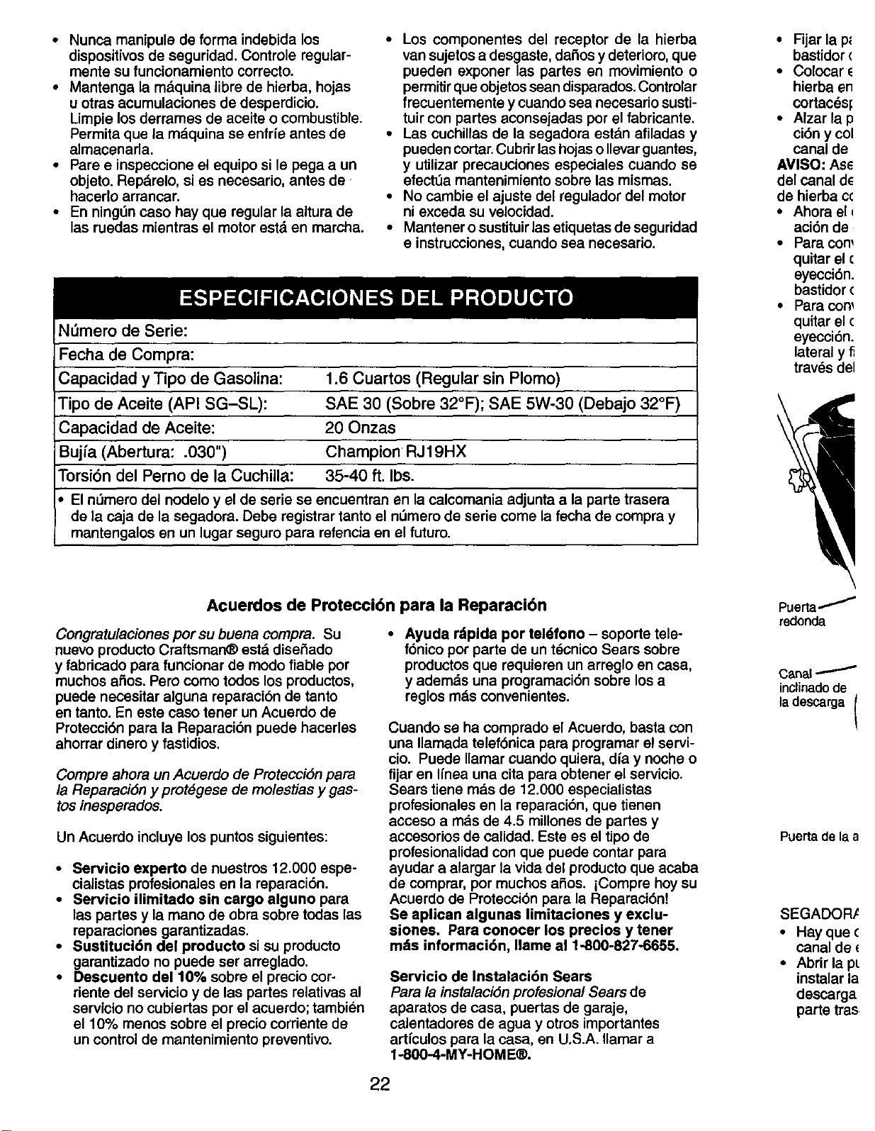
N_mero de Serie:
Fecha de Compra:
Capacidad y Tipo de Gasolina: 1.6 Cuartos (Regular sin Plomo)
Tipo de Aceite (API SG-SL): SAE 30 (Sobre 32°F); SAE 5W-30 (Debajo 32°F)
Capacidad de Aceite: 20 Onzas
Bujfa (Abertura: .030") Champion RJ19HX
Torsi6n del Perno de la CuchUla: 35-40 ft. Ibs.
Eln_mero del nodelo y el de serie se encuentran en lacalcomania adjunta a la parte trasera
de la caja de la segadora. Debe registrar tanto el n_mero de serie come la fecha de compra y
mantengalos en un lugar seguro para refencia en el futuro.
• Fijar la p_
bastidor (
• Colocar
hierba en
cortac_sf
• Alzar lap
ci6n y col
canal de
AVISO: As_
del canal d_
de hierba c<
• Ahora el i
aci6n de
• Para con_
quitar el (
eyecci6n.
bastidor (
• Para con_
quitar el (
eyecci6n.
lateral y fi
tray,s del
Acuerdos de Protecci6n para la Reparaci6n
Congratulaciones por su buena compra. Su
nuevo producto Craftsman® est& diser3ado
y fabricado para funcionar de modo fiable por
rnuchos afios. Pero como todos los productos,
puede necesitar alguna reparaci6n de tanto
en tanto. En este caso tener un Acuerdo de
Protecci6n para la Reparaci6n puede hacerles
ahorrar dinero y fastidios.
Compre ahora un Acuerdo de Protecci6n para
la Reparaci6n y prot_gese de molestias y gas-
toe inesperados.
Un Acuerdo incluye los puntos siguientes:
• Servicio experto de nuestros 12.000 espe-
cialistas profesionales en la reparaci6n.
• Servicio ilimitado sin cargo alguno para
las partes y la mano de obra sobre todas las
reparaciones garantizadas.
• Sustituci6n del producto si su producto
garanUzado no puede ser arreglado.
• Descuento de110% sobre el precio cor-
riente del servicio y de las partes relativas al
servicio no cubiertas por el acuerdo; tambien
el 10% menos sobre el precio corriente de
un control de mantenimiento preventivo.
• Ayuda rdpida por teldfono - soporte tele-
f6nico por parte de un tdcnico Sears sobre
productos que requieren un arreglo en casa,
y ademds una pmgramaci6n sobre los a
reglos rods convenientes.
Cuando se ha comprado el Acuerdo, basta con
una Ilamada telef6nica para programar el servi-
cio. Puede Ilamar cuando quiera, diay noche o
fijar en Ifnea una cita para obtener el servicio.
Sears tiene m&s de 12.000 especialistas
profesionales en la reparaci6n, que tienen
acceso a rods de 4.5 millones de partes y
accesorios de calidad. Este es el tipo de
profesionalidad con que puede contar para
ayudar a alargar la vida del producto que acaba
de comprar, por muchos aSos. iCompre boy su
Acuerdo de Protecci6n para la Reparaci6n!
Se aplican algunas limitaciones y exclu-
aiones. Para conocer los precios y tener
m_is informaci6n, Ilame al 1-800-827-6655.
Servicio de Instalaci6n Sears
Para la instalacidn profesional Sears de
aparatos de casa, puertas de garaje,
calentadores de agua y otros importantes
artfculos para la casa, en U.S.A. Ilamar a
1-800-4-MY-HOM E®.
Puerta_
redonda
Canal l
inclinadode
ladescarga (
Puerta de la a
SEGADOR,_
• Hayque (
canal de
• Abrir la pt
instalar la
descarga
parte tras
22
de transmisiOn
ser sustituida.
.=nciadeloperador
;ontrol de
i impulsion
CONTROL DE LA
IMPULSION
!SENGANCHADO
)E CORTE
ustan a traves
a delantera
das traseras
palanca en la
icia la rueda. Le-
Llancahasta del-
ra bajar la sega-
=la retaguardia.
_s delanteras y
sma altura.
_,DELANTEPARA
CORTACI_SPED
ORA
ra usarse
tal. Para con-
;ado posterior
TRASERA
ta del acaba-
t.
introducir
=argaen la
ulaciOn y
_osobre el
;carga
le la acolchadora
_kADVERTENCIA: Este segadora viene equipado con un motor de combusti6n interna y no se
debe usar sobre, o cerca, de un terreno no desarrollado cubierto de bosques, de arbustos o de
c6sped, o menos que el sistema de escape del motor venga equipado con un amorUguador de
chispas que cumpla con las leyes locales o estatales (si existen). Si se usa un amortiguador de
chispas, el operador debe mantenerlo en condiciones de trabajo eficientes.
En el estado de California, la ley exige Io anterior (Secci6n 4442 del "California Public Re-
sources Code"). Otros estados pueden contar con otras leyes parecidas. Las leyes fedsrales
se aplican en la tierras federales. Su centro de Servicio rods cercano tiene disponible amor-
tiguadores de chispas para el silenciador (Vea la secci6n de PARTES DE REPUESTO en el
manual Ingles del duefio),
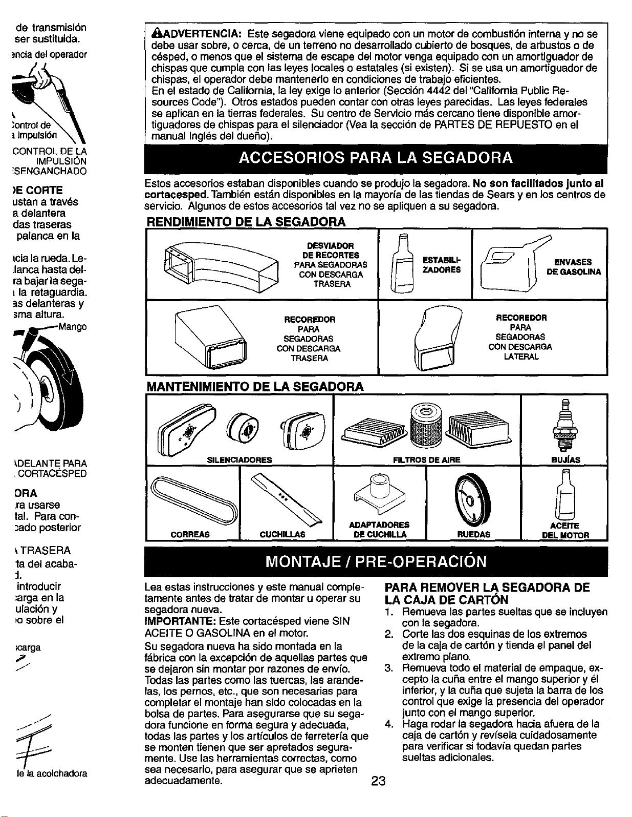
Estos accesorios estaban disponibles cuando se produjo la segadora. No son facilitados junto al
cortacesped. Tarnbien estdn disponibles en la mayoria de las tiendas de Sears yen los centros de
servicio. Algunos de estos accesorios tal vez no se apliquen a su segadora.
RENDIMIENTO DE LA SEGADORA
DESVIADOR
DE RECORTES
PAPA SEGADORAS
CON DESCARGA
TRASERA
RECOREDOR
PAPA
SEGADORAS
CON DESCARGA
TRASERA
ESTABILI-
ZADORES
_D ENVASES
E GASOLINA
RECOREDOR
PAPA
SEGADORAS
CON DESCARGA
LATERAL
MANTENIMIENTO DE LA SEGADORA
SILENCIADORES
CORREAS
CUCHILLAS
ADAPTADORES
DE CUCHILLA
RLTROS DE AIRE
RUEDAS
BUJ|AS
ACEITE
DEL MOTOR
Lea estas instrucciones y este manual comple-
tamente antes de tratar de montar u operar su
segadora nueva.
IMPORTANTE: Este cortac_sped viene SIN
ACEITE O GASOLINA en el motor.
Su segadora nueva ha sido montada en la
f_.brica con la excepci6n de aquellas partes que
se dejaron sin montar por razones de envfo.
Todas las partes como las tuercas, las arande-
las, los pernos, etc., que son necesarias para
completar el montaje han sido colocadas en la
bolsa de partes. Para asegurarse que su sega-
dora funcione en forma segura y adecuada,
todas las partes y los artfculos de ferreterfa que
se monten tienen que ser apretados segura-
mente. Use las herramientas correctas, como
sea necesario, para asegurar que se aprieten
adecuadamente.
PARA REMOVER LA SEGADORA DE
LA CAJA DE CART6N
1. Remueva las partes sueltas que se incluyen
con la segadora.
2. Corte las dos esquinas de los extremos
de la caja de cart6n y tienda el panel del
extremo piano.
3. Remueva todo el material de empaque, ex-
cepto la curia entre el mango superior y _1
inferior, y la curia que sujeta la barra de los
control que exige la presencia del operador
junto con el mango superior.
4. Haga rodar la segadora hacia afuera de la
caja de cart6n y revfsela cuidadosamente
para verificar si todav_a quedan partes
sueltas adicionales.
23
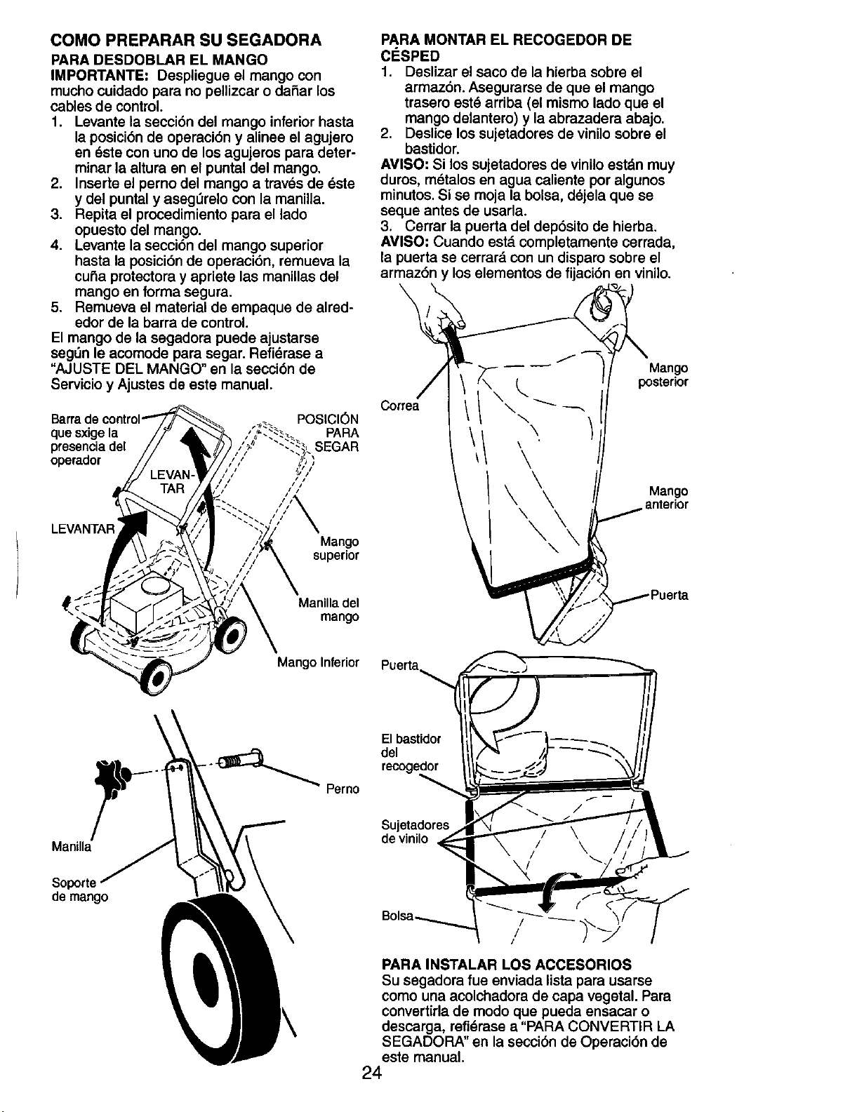
COMO PREPARAR SU SEGADORA
PARA DESDOBLAR EL MANGO
IMPORTANTE: Despliegue el mango con
mucho cuidado para no pellizcar o daSar los
cables de control.
1. Levante la secci6n del mango inferior hasta
la posici6n de operaci6n y alinee el agujero
en _ste con uno de los agujeros para deter-
minar la altura en el puntal del mango.
2. Inserte el perno del mango a traves de _ste
y del puntal y asegL_relocon la manilla.
3. Repita el procedimiento para el lado
opuesto del mango.
4. Levante la secci6n del mango superior
hasta la posici6n de operaci6n, remueva la
cuba protectora y apriete las manillas del
mango en forma segura.
5. Remueva el material de empaque de alred-
edor de la barra de control.
El mango de la segadora puede ajustarse
segL_nle acomode para segar. Refi_rase a
"AJUSTE DEL MANGO" en la secci6n de
Servicio y Ajustes de este manual.
POSICl6N
quesxigela PARA
presencia del SEGAR
operador
/
LEVANTAR
Mango
superior
PARA MONTAR EL RECOGEDOR DE
ClaSPED
1. Deslizar el saco de la hierba sobre el
armaz6n. Asegurarse de que el mango
trasero est_ arriba (el mismo lado que el
mango delantero) y la abrazadera abajo.
2. Deslice los sujetadores de vinilo sobre el
bastidor.
AVlSO: Si los sujetadores de vinilo est_n muy
duros, m_talos en agua caliente por algunos
minutos. Si se moja la bolsa, d_jela que se
seque antes de usarla.
3. Cerrar la puerta del dep6sito de hierba.
AVlSO: Cuando est,. completamente cerrada,
la puerta se cerrar_ con un disparo sobre el
armaz6n y los elementos de fijaci6n en vinilo.
Correa
\
\
\
/\\\
\
Mango
posterior
Mango
anterior
Manilla del
mango
ManUla
Soporte
de mango
Mango Inferior
El bastidor
del -_'_
recoge_.._
Sujetadores
de vinilo
/
!
PARA INSTALAR LOS ACCESORIOS
Su segadora fue enviada lista para usarse
como una acolchadora de capa vegetal. Para
convertirla de modo que pueda ensacar o
descarga, refi_rase a "PARA CONVERTIR LA
SEGADORA" en la secci6n de Operaci6n de
este manual.
24
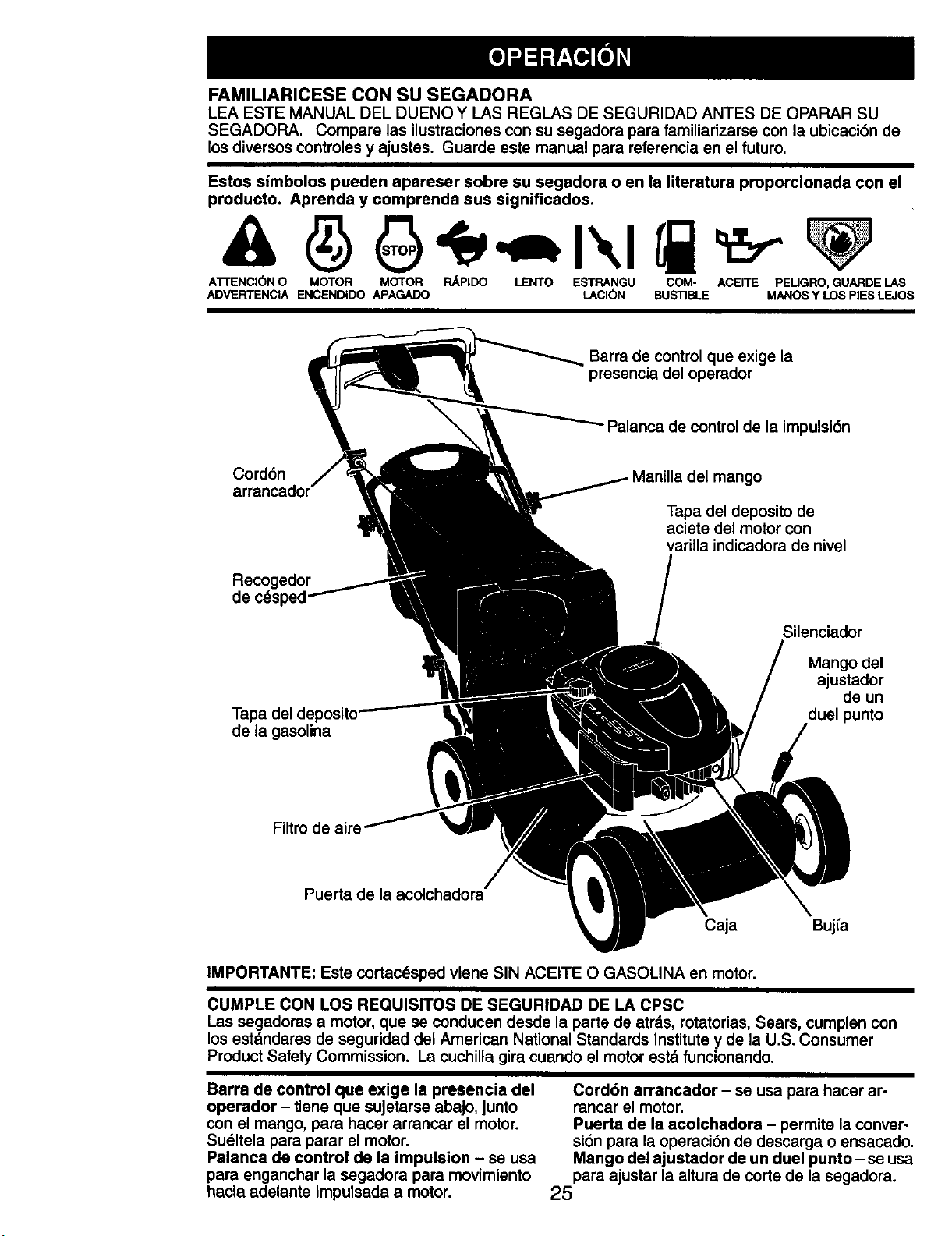
FAMILIARICESECONSUSEGADORA
LEAESTEMANUALDELDUENOYLASREGLASDESEGURIDADANTESDEOPARARSU
SEGADORA.Comparelasilustracionesconsusegadoraparafamiliarizarse con la ubicaci6n de
los diversos controles y ajustes. Guarde este manual para reterencia en el futuro.
Estos sfmbolos pueden apareser sobre su segadora o en la literatura proporcionada con el
producto. Aprenda y comprenda sus significados.
A'FrENCI(_N O MOTOR MOTOR PJd_IDO LENTO ESTRANGU COM- ACEITE PEUGRO, GUARDE I.AS
ADVERTENCIA ENCENDIDO APAGADO LACI6N BUSTIBLE MANOS Y LOS PiES LEJOS
Barra de control que exige la
presencia del operador
- Palanca de control de la impulsi6n
Cord6n
Recogedor
del mango
Tapa del deposito de
aciete del motor con
varilla indicadora de nivel
Tapa del
de la gasolina
Silenciador
Mango del
_ustador
de un
duelpunto
Puerta de la acolchadora
Caja Bujfa
IMPORTANTE: Este cortac6sped viene SIN ACEITE O GASOLINA en motor.
CUMPLE CON LOS REQUlS|TOS DE SEGURIDAD DE LA CPSC
Las segadoras a motor, que se conducen desde la parte de atrds, rotatorias, Sears, cumplen con
los estdndares de seguridad del American National Standards Institute y de la U.S. Consumer
Product Safety Commission. La cuchilla gira cuando el motor estd funcionando.
Barra de control que exige la presencia del
operador - tiene que sujetarse abajo, junto
con el mango, para hacer arrancar el motor.
Sueltela para parar el motor.
Palanca de control de la impulsion - se usa
para enganchar la segadora para movimiento
hacia adelante impulsada a motor.
Cord6n arrancador - se usa para hacer ar-
rancar el motor.
Puerta de la acolchadora - permite la conver-
si6n para la operaci6n de descarga o ensacado.
Mango del ajustador de un duel punto- se usa
para ajustar la altura de corte de la segadora.
25
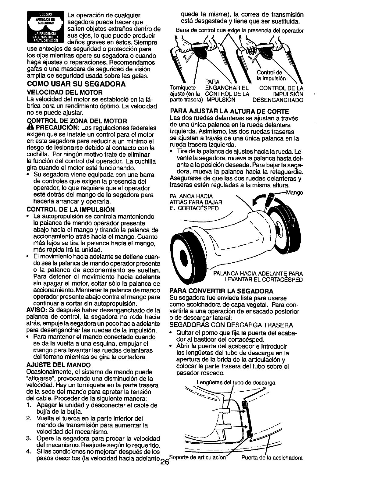
La operaci6n de cualquier
segadora puede hacer que
salten objetos extraSos dentro de
sus ojos, Io que puede producir
daSos graves en _stos. Siempre
use anteojos de seguridad o protecci6n para
los ojos mientras opera su segadora o cuando
haga ajustes o reparaciones. Recomendamos
gafas o una mascara de seguridad de visi6n
amplia de seguridad usada sobre las gafas.
COMO USAR SU SEGADORA
VELOCIDAD DEL MOTOR
La velocidad del motor se estableci6 en la f_-
brica para un rendimiento 6pfimo. La velocidad
no se puede ajustar.
dI_NTROL DE ZONA DEL MOTOR
PRECAUClON" Las regulaciones federales
exigen que se instale un control para el motor
en esta segadora para reducir a un mfnimo el
riesgo de lesionarse debido al contacto con la
cuchilla. Por ning_n motivo trate de eliminar
la funci6n del control del operador. La cuchilla
gira cuando el motor est_ funcionando.
• Su segadora viene equipada con una barra
de controles que exigen la presencia del
operador, Io que requiere que el operador
est_ detr_s del mango de la segadora para
hacerla arrancar y operarla.
CONTROL DE LA IMPULSI(_N
• La autopropulsi6n se controla manteniendo
la palanca de mando operador presente
abajo hacia el mango y tirando la palanca de
accionamiento at_s hacia el mango. Cuanto
m_.s lejos se tira la palanca hacia el mango,
m_.sr_pida ir_ la unidad.
• El movimiento hacia adelante se detiene cuan-
do sea la palanca de mando operador presente
o la palanca de accionamiento se sueltan.
Para detener el movimiento hacia adelante
sin apagar el motor, soltar s61ola palanca de
accionamiento. Mantener la palanca de mando
operador presente abajo contra el mango para
continuar a cortar sin autopropulsi6n.
AVlSO: Si despues haber desenganchado de la
palanca de control, la segadora no roda hacia
atr__s,empuje la segadora un poco hacia adelante
para desenganchar las ruedas de la impulsi6n.
• Para mantener el mando conectado cuando
se da la vuelta a una esquina, empujar el
mango para levantar las ruedas delanteras
del terreno mientras se gira la cortadora.
AJUSTE DI=L MANDO
Ocasionalmente, el sistema de mando puede
"aflojarse", provocando una disminuci6n de la
velocidad. Hay un torniquete en la parte trasera
de la sede del mando para apretar la tensi6n
del cable. Procader de la siguiente manera:
1. Apagar la unidad y desconectar el cable de
bujfa de la bujfa.
2. Vuelta el tuerca en la parte inferior del
mando de transmisi6n para aumentar la
velocidad del mecanismo.
3. Opera la segadora para probar la velocidad
del mecanismo. Reajuste segl_n Io requerido.
4. Si las condiciones no mejoran despu_s de los
pasos descritos (la velocidad hacia adelante 2_u
queda la misma), la correa de transmisi6n
est_ldesgastada y tiene que ser sustituida.
Barra decontrol que
PARA
Torniquete ENGANCHAR EL
ajuste (en la CONTROL DE LA
parte trasera) IMPULSION
Control d_
la impulsi6n
CONTROL DE LA
IMPULSION
DESENGANCHADO
PARA AJUSTAR LA ALTURA DE CORTE
Las dos ruedas delanteras se ajustan a trav_s
de una Onica palanca en la rueda delantera
izquierda. Asimismo, las dos ruedas traseras
se ajustan a trav_s de una L_nicapalanca en la
rueda trasera izquierda.
• Tire de la palanca de ajustes hacia la rueda. Le-
vante lasegadora, mueva la palanca hasta del-
ante a la posici6n deseada. Para bajar la sega-
dora, mueva la palanca hacia la retaguardia.
Asegurarse de que las dos ruedas delanteras y
traseras est_n reguladas a la misma altura.
PALANCAHAClA
ATRASPARABAJAR
ELCORTACI_SPED
PALANCA HACIA ADELANTE PARA
LEVANTAR EL CORTAC_SPED
PARA CONVERTIR LA SEGADORA
Su segadora fue enviada lista para usarse
como acolchadora de capa vegetal. Para con-
vertirla a una operaci6n de ensacado posterior
o de descargar lateral:
SEGADORAS CON DESCARGA TRASERA
• Quitar el pomo que fija la puerta del acaba-
dor al bastidor del cortacesped.
• Abrir la puerta del acabador e introducir
las lengQetas del tubo de descarga en la
apertura de la brida de la articulaci6n y
colocar la parte trasera del tubo sobra el
pasador roscado.
LengQetas del tubo de descarga
Puerta de la acolchadora
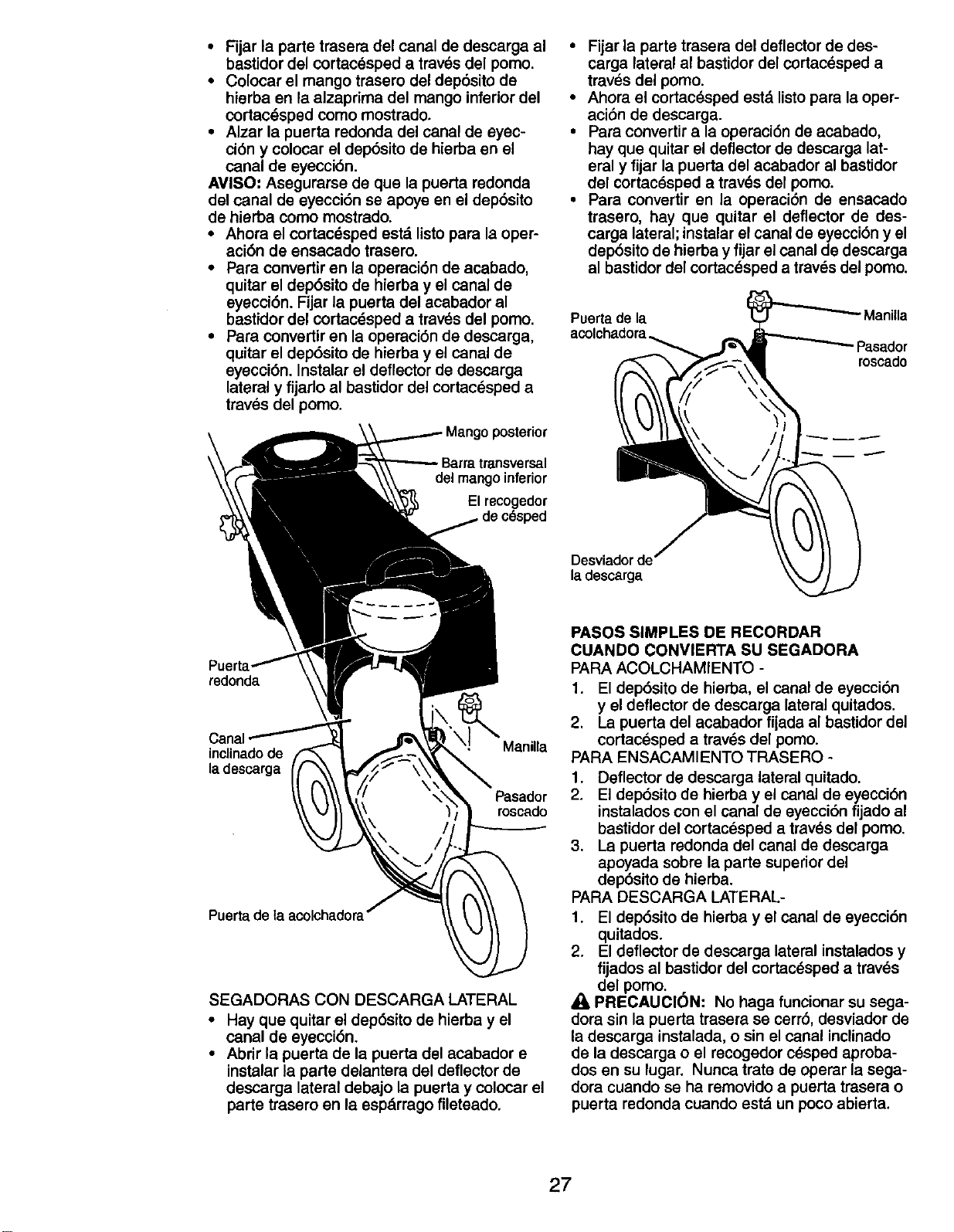
• Fijar la parte trasera del canal de descarga al
bastidor del cortacesped a tray,s del pomo.
• Colocar el mango trasero del dep6sito de
hierba en la alzaprima del mango inferior del
cortac_sped como mostrado.
• Alzar la puerta redonda del canal de eyec-
ci6n y colocar el dep6sito de hierba en el
canal de eyecci6n.
AVISO; Asegurarse de que la puerta redonda
del canal de eyecci6n se apoye en el dep6sito
de hierba como mostrado.
• Ahora el cortac_sped estd listo para la oper-
aci6n de ensacado trasero.
• Para convertir en la operaci6n de acabado,
quitar el dep6sito de hierba y el canal de
eyecci6n. Fijar la puerta del acabador al
bastidor del cortacdsped a trav_s del pomo.
• Para convertir en la operaci6n de descarga,
quitar el dep6sito de hierba y el canal de
eyecci6n. Instalar el deflector de descarga
lateral y fijado al bastidor del cortac_sped a
tray,s del pomo.
transversal
del mangoinferior
El recogedor
redonda
inclinadode Manilla
la descarga
Pasador
roscado
Puerta de taacolchadora
SEGADORAS CON DESCARGA LATERAL
• Hay que quitar el dep6sito de hierba y el
canal de eyecci6n.
• Abrir la puerta de la puerta del acabador e
instalar la parte delantera del deflector de
descarga lateral debajo la puerta y colocar el
parte trasero en la espdrrago fileteado,
• Fijar la parte trasera del deflector de des-
carga lateral al bastidor del cortac_sped a
trav_s del pomo.
• Ahora el cortac_sped estd listopara la oper-
aci6n de descarga.
• Para convertir a la operaci6n de acabado,
hay que quitar el deflector de descarga lat-
eral y fijar la puerta del acabador al bastidor
del cortac_sped a trav_s del pomo.
• Para convertir en la operaciOn de ensacado
trasero, hay que quitar el deflector de des-
carga lateral; instalar el canal de eyecci6n y el
dep6sito de hierba y fijar el canal de deecarga
al bastidor del cortacesped a traves del pomo.
Puertade la Manilla
acolchadora
roseado
Desviadorde
la descarga
PASOS SIMPLES DE RECORDAR
CUANDO CONVIERTA SU SEGADORA
PARA ACOLCHAMIENTO -
1. El dep6sito de hierba, el canal de eyecci6n
y el deflector de descarga lateral quitados.
2. La puerta del acabador fijada al bastidor del
cortac_sped a trav_s del pomo.
PARA ENSACAMIENTO TRASERO -
1. Deflector de descarga lateral quitado.
2. El dep6sito de hierba y el canal de eyecci6n
instalados con el canal de eyecci6n fijado al
bastidor del cortac_sped a trav_s del pomo.
3. La puerta redonda del canal de descarga
apoyada sobre la parte superior del
dep6sito de hierba.
PARA DESCARGA LATERAL-
1. El dep6sito de hierba y el canal de eyecci6n
quitados.
2. El deflector de descarga lateral instalados y
fijados al bastidor del cortac_sped a traves
del pomo.
PRECAUClON: No haga funcionar su sega-
dora sin la puerta trasera ee cerr6, desviador de
la descarga instalada, o sin el canal inclinado
de la descarga o el recogedor cesped aproba-
dos en su lugar. Nunca trate de operar la sega-
dora cuando se ha removido a puerta trasera o
puerta redonda cuando estd un poco abierta.
27
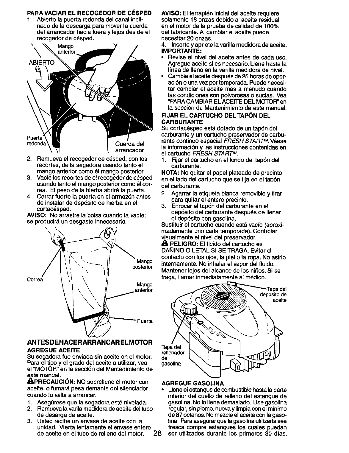
PARA VAClAR EL RECOGEDOR DE ClaSPED
1. Abierto la puerta redonda del canal incli-
nado de la descarga para mover la cuerda
del arrancador hacia fuera y lejos des de el
recogedor de c_sped.
\ Mango
ABIERTO
redond_ Cuerda del
arrancador
2. Remueva el recogedor de cesped, con los
recortes, de la segadora usando tanto el
mango anterior como 51mango posterior.
3. Vacfe los recortes de el recogedor de cesped
usando tanto el mango posterior como el cor-
rea. El peso de la hierba abrird la puerta.
4. Cerrar fuerte la puerta en el armaz6n antes
de instalar de dep6sito de hierba en el
cortacdsped.
AVISO" No arrastre la bolsa cuando la vacie;
se pmducird un desgaste innecesario.
Correa
Mango
posterior
Mango
anterior
\
AVISO" El terrapldn inicial del aceite requiere
solamente 18 onzas debido al aceite residual
en el motor de la prueba de calidad de 100%
del fabricante. AI cambiar el aceita puede
necesitar 20 onzas.
4. Inserte y apriete lavarilla medidora de aceite.
IMPORTANTE:
• Revise el nivel del aceite antes de cacla uso.
Agregue aceite si es necesario. Uene hasta la
Ifnea de Ileno en la varUla medidora de nivel.
• Cambie el aceite despuds de 25 horas de oper-
aci6n o una vez portemporeda. Puede necesi-
tar cambiar el aceite rods a menudo cuanclo
las condiciones son poIvoresas o sucias. Vea
"PARA CAMBIAR EL ACEITE DEL MOTOR" en
la seccion de Mantenimiento de este manual.
FIJAR EL CARTUCHO DELTAPON DEL
CARBURANTE
Su cortacdsped est,, dotado de un tap6n del
carburante y un cartucho preservador de carbu-
rente continuo especial FRESH START =.V_asa
la intormaci6n y las instrucciones contenidas en
el cartucho FRESH START=.
1. Fijar el cartucho en el fondo del tap6n del
carburante.
NOTA: No quitar el papel plateado de precinto
en el lado del cartucho que se fija en el tap6n
del carburente.
2. Agarrer la etiqueta blanca removible y tirar
para quitar el entero precinto.
3. Enrocar el tap6n del carburante en el
dep6sito del carburante despuds de Ilenar
el dep6sito con gasolina.
Sustituir el cartucho cuando estd vacfo (aproxi-
madamente uno cada temporada). Controlar
visualmente el nivel del preservador.
• 1,PELIGRO: El fluido del cartucho es
DAI_IINO O LETAL SI SE TRAGA. Evitar el
contacto con los ojos, la piel o la ropa. No asirlo
internamente. No inhalar el vapor del fluido.
Mantener lejos del alcance de los nifios. Si se
traga, Ilamar inmediatamente al mddico.
deposito de
aceite
ta
ANTESDEHACERARRANCAR ELMOTOR
AGREGUE ACEITE
Su segadora fue anviada sin aceite an el motor,
Para el tipo y el grado del aceite a utilizar, vea
el "MOTOR" en la secci6n del Mantenimiento de
este manual.
_II,PRECAUCI6N: NO sobrellene el motor con
aceite, o fumard pesa demante del silenciador
cuando Io valla a arrancar.
1. Asegdrese que la segadore estd nivelada.
2. Remuevalavadlamedidoredeaceitedeltubo
de desarga de aceite.
3. Usted recibe un envase de aceite con la
unidad. Vierta lentamente el envase entero
de aceite en el tubo de relleno del motor. 28
Tapadel
rellenedor
de
gasolina
AGREGUE GASOLINA
• Uene el estanque de combustible hasta la parte
inferior del cuello de relleno del estanque de
gasoUna. No Io Ilene demasiado. Use gasolina
regular, sinplomo, nueva y limpia con el mfnimo
de 87 octanos. No mezcle el aceite con la gaso-
lina. Para asegurar que la gasolina ulilizada sea
fresca compre estanques los cuales puedan
ser utilizados durante los primeros 30 dfas.
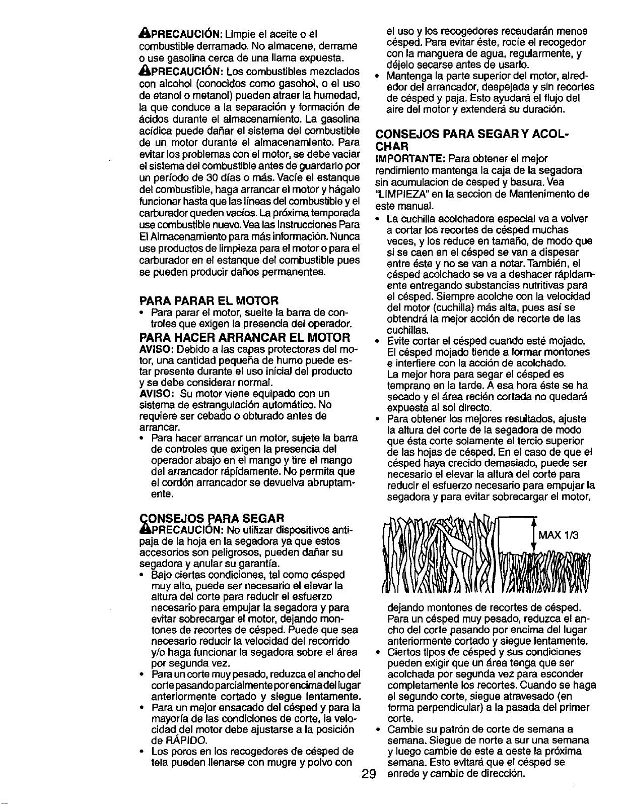
_IPRECAUCI6N: Limpie el aceite o el
combustible derramado. No almacene, derrame
o use gasolina cerca de una llama expuesta.
_PRECAUCl6N: Los combustibles mezclados
con alcohol (conocidos como gasohol, o el uso
de etanol o metanol) pueden atraer la humedad,
la que conduce a la separaci6n y formaci6n de
dcidos durante el almacenamiento. La gasolina
acidica puede daSar el sistema del combustible
de un motor durante el almacenamiento. Para
evitar los problemas con el motor, se debe vaciar
el sistema del combustible antes de guardarlo por
un perfodo de 30 dfas o mds. Vacfe el estanque
del combustible, haga arrancar el motor y h&galo
funcionar hasta que las lineas del combustible y el
carburador queden vacfos. La pr6xima temporada
use combustible nuevo.Vea las Instrucoiones Para
El AImacenamiento para m&s informacibn. Nunca
use productos de limpieza para el motor o para el
carburador en el estanque del combustible pues
se pueden producir da_os permanentes.
PARA PARAR EL MOTOR
• Para parar el motor, suelte la barra de con-
tmles que exigen la presencia del operador.
PARA HACER ARRANCAR EL MOTOR
AVISO: Debido alas capas protectoras del mo-
tor, una cantidad pequeSa de humo puede es-
tar presente durante el uso inicial del producto
y se debe considerar normal.
AVISO: Su motor viene equipado con un
sistema de estrangulaci6n automdtico. No
requiem ser cebado o obturado antes de
arrancar.
• Pare hacer arrancar un motor, sujete la barra
de controles que exigen la presencia del
operador abajo en el mango y tire el mango
del arrancador r_pidamente. No permita que
el cord6n arrancador se devuelva abruptam-
ente.
,_ONSEJOS PARA SEGAR
RECAUCION: NO utilizar dispositivos anti-
paja de la hoja en la segadora ya que estos
accesorios son peligrosos, pueden daSar su
segadora y anular su garantfa.
• Bajo ciertas condiciones, tal como c6sped
muy alto, puede ser necesario el elevar la
altura del corte para reducir el esfuerzo
necesario para empujar la segadora y para
evitar sobrecargar el motor, dejando mort-
tones de recortes de cdsped. Puede que sea
neceserio reducir la velocidad del recorrido
y/o haga funcionar la segadora sobre el drea
por segunda vez.
• Para uncorte muy pesado, reduzca el ancho del
corte pasendo parcialmente porencimadel lugar
anteriormente cortado y siegue lentamente.
• Para un mejor ensacado del cOsped y para la
mayorfa de las condiciones de corte, la velo-
cidad del motor debe ajustarse a la posici6n
de RAPIDO.
• Los pores en los recogedores de c_sped de
tela pueden Ilenarse con mugre y polvo con
el uso y los recogedores recaudardn menos
c_sped. Para evitar _ste, rocfe el recogedor
con la manguera de agua, regularmente, y
d_jelo secarse antes de usarlo.
• Mantenga la parte superior del motor, alred-
edor del arrancador, despejada y sin recortes
de cdsped y paja. Esto ayudard el flujo del
aire del motor y extenderd su duraci6n.
CONSEJOS PARA SEGAR Y ACOL-
CHAR
IMPORTANTE" Para obtener el mejor
rendimiento mantenga la caja de la segadora
sin acumulacion de cesped y basura. Vea
"LIMPIEZA" en la seccion de Mantenimento de
este manual.
• La cuchilla acolchadora especial va a volver
a cortar los recortes de cdsped muchas
veces, y los reduce en tamaSo, de modo que
si se caen en el c_sped se van a dispesar
entre _ste y no se van a notar.Tambidn, el
c_sped acolchado se va a deshacer rdpidam-
ente entregando substancias nutritivas para
el c_sped. Siempre acolche con la velocidad
del motor (cuchilla) rods alta, pues asi se
obtendrd la mejor acci6n de recorte de las
cuchUlas.
• Evite cortar el cdsped cuando est_ mojado.
El c_sped mojado tiende a formar montones
e interfiere con la acci6n de acolchado.
La mejor hora para segar el cdsped es
temprano en la tarde. A ese hora dste se ha
seoado y el drea reci_n cortada no quedard
expuesta al sol directo.
• Para obtener los mejores resultados, ajuste
la altura del corte de la segadora de modo
que dsta corte solamente el tercio superior
de las hojas de cesped. En el caso de que el
c_sped haya crecido demasiado, puede ser
necesario el elevar la altura del corte para
reducir el esfuerzo necesario para empujar la
segadora y para evitar sobrecargar el motor,
dejando montones de recortes de c_sped.
Pare un cdsped muy pesado, reduzca el an-
cho del corte pasando pot encima del lugar
anteriormente cortado y siegue lentamente.
• Ciertos tipos de c_sped y sus condiciones
pueden exigir que un drea tenga que ser
acolchada por segunda vez para esconder
completamente los recortes. Cuando se haga
el segundo corte, siegue atravesado (en
forma perpendicular) a la pasada del primer
corte.
• Cambie su patr6n de corte de semana a
semana. Siegue de norte a sur una semana
y luego cambie de este a oeste la pr6xima
semana. Esto evitard que el c_sped se
29 enrede y cambie de direcci6n.
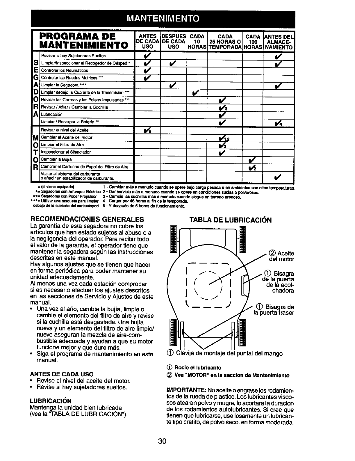
PROGRAMA DE ANTES DESPUES CADA ANTESDEL
DE CADA CADA 25 HORAS q ALMACE-
MANTENIMIENTO uso uso NAMIENTO
Revisar si hay Sujetadores Sueltos _ _1
S I Impiar/lnspeccionar el Recogedor de Cdsped *
Contro/arlosNeumdticos
AG ControlarlasRuedas Motrices**"
Limpiar la Segadora .... _
D Limplardebajola Cubtertade _aTransmisi6n***
Revisar las Correas y las Poleas Impulsadas *** I_
R Revisar/ Afitar/ CarnbiarlaCuchilla
Lubricaci0n
Limpiar/Recargar la Boter[a ** _ 1_4
Revlsar el nivei del Aceite
_ CambiarelAceitedel motor _T 2
Limpiar el Filtro de Aim
T inspeccionarel Silenciador
Carnbiaf la Bujfa _2
R CambiarelCartuchode Pape[del FiltrodeAire
Vaciarel sistemadelcarburante
o a_adirun estabilizadorde carburante. I_
* (sivieneequipado) 1-Cambiarmds a menudocuandoeeoperebajo cargapesadao en ambientescon altM temperaturas.
** SegadorasconArranqueEMctr_€o2 - Dar sendciom_sa menudocuando$e opereen condiclonessuciaso potvomsas.
*** SegadomsconPoderPropulsor 3 - Carnl0ieles cuchillasmds a mefludo¢uandoslegueenterrsflo_,
**** UtilizarunarasquetaparaIlmplar 4 - Cargarpo_48 horasaJfin de latemporad_L
debajode Isc_biertadelcortacd_ped 5 - Y despu_sde 5 hora_de funclonamlento.
RECOMENDACIONES GENERALES
La garantfa de esta segadora no cubre los
articulos que han estado sujetos al abuso o a
la negligencia del operador. Para recibir todo
el valor de la garant_a, el operador tiene que
mantener la segadora seg_n las instrucciones
descritas en este manual.
Hay algunos ajustes que se tienen que hacer
sn forma peri_:lica para poder mantener su
unidad adecuadamente.
AI menos una vez cada estaci<_ncomprobar
si es necesario efectuar los ajustes descritos
en las secciones de Servicio y Ajustes de este
manual.
• Una vez al ai_o, cambie la buj(a, limpie o
cambie el elemento del filtro de aire y revise
si la cuchilla estd desgastada. Una bujfa
nueva y un elemento del filtro de aim limpio/
nuevo aseguran la mezcla de aire-com-
bustible adecuada y ayudan a que su motor
funciona mejor y que dure rods.
• Siga el programa de rnantenimiento en este
manual.
ANTES DE CADA USO
• Revise el nivel del aceite del motor.
• Revise si hay sujetadoras sueltos.
LUBRICACI()N
Mantenga la unidad bien lubricada
(yea la 'qABLA DE LUBRICACION").
TABLA DE LUBRICACI6N
) Aceite
del motor
Bisagra
de la puerta
de la acol-
chadora
,ade
(_) Clavija de montaje del puntal del mango
(_ Rocle el lubricante
(_ Vea "MOTOR" en la secclon de Mantenimiento
IMPORTANTE: No aceite oengrase los rodamien-
tos de la rueda de plastico. Los lubricantes visco-
sos atearan polvo y mugre, Ioacortara la duracion
de los rodamientos autolubricantes. Si cree que
tienen que lubricarse, use Iosamente un lubrican-
ta tipo crafito, de polvo seco, en forma moderada.
3O
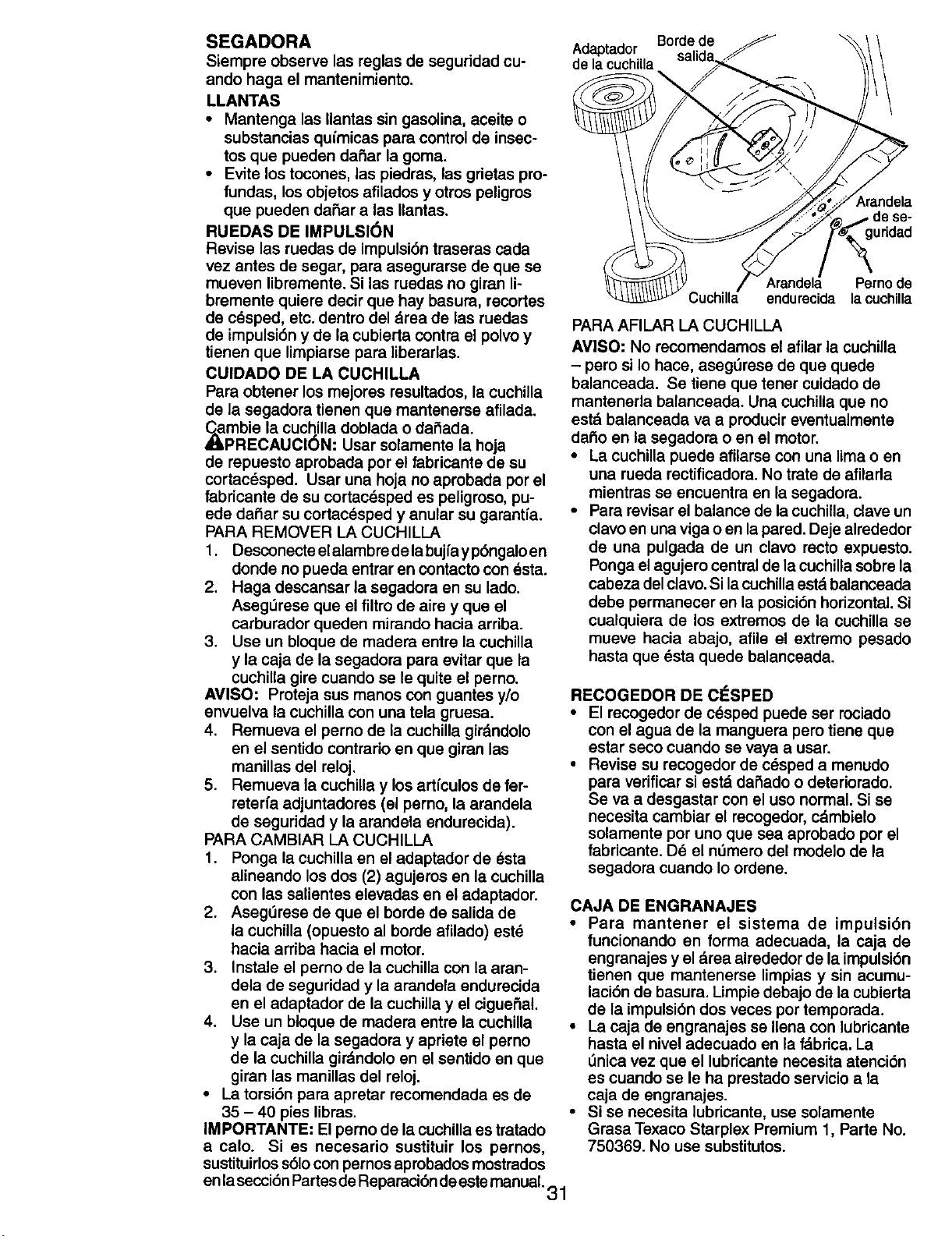
SEGADORA
Siempre observe las reglas de seguridad cu-
ando haga el mantenimiento.
LLANTAS
• Mantenga las Ilantas sin gasolina, aceite o
substancias quimicas para control de insec-
tos que pueden dafiar la goma.
• Evite los tocones, las piedres, las grietas pro-
fundas, los objetos afilados y otros peligros
que pueden dafiar alas Ilantas.
RUEDAS DE IMPULSION
Revise las ruedas de impulsi6n traseras cada
vez antes de segar, para asegurarse de que se
mueven libremente. Si las ruedas no giren li-
brernente quiere decir que hay basura, recortes
de c_sped, etc. dentro del Area de las ruedas
de impulsi6n y de la cubierta contra el polvo y
tienen que limpiarse para libererlas.
CUIDADO DE LA CUCHILLA
Pare obtener los mejores resultados, la cuchilla
de la segadora tienen que mantenerse afilada.
_mbie la cuchilla doblada o dafiada.
PRECAUCl6N" Usar solamente la hoja
de repuesto aprobada por el fabricante de su
cortacesped. Usar una hoja no aprobada por el
fabricante de su cortac_sped es peligroso, pu-
ede dafiar su cortac_sped y anular su garanfia.
PARA REMOVER LA CUCHILLA
1. Desconecte el alambre de la bujfa y p6ngalo en
donde no pueda entrar en contacto con _sta.
2. Haga descansar la segadora en su lado.
Asegt_rese que el filtro de aire y que el
carburador queden mirando hacia arriba.
3. Use un bloque de madera entre la cuchilla
y la caja de la segadora para evitar que la
cuchilla gire cuando se le quite el perno.
AVISO: Proteja sus manos con guantes y/o
envuelva la cuchilla con una tela gruesa.
4. Remueva el perno de la cuchilla gir&ndolo
en el sentido contrario en que giran las
manillas del reloj.
5. Remueva la cuchilla y los artfculos de fer-
reterfa adjuntadores (el perno, la arandela
de seguridad y la arandela endurecida).
PARA CAMBIAR LA CUCHILLA
1. Ponga la cuchilla en el adaptador de 6sta
alineando los dos (2) agujeros en la cuchilla
con las salientes elevadas en el adaptador.
2. Asegerese de que el borde de salida de
la cuchilla (opuesto al borde afilado) est_
hacia arriba hacia el motor.
3. Instale el perno de la cuchilla con la aran-
dela de seguridad y la arendela endurecida
en el adaptador de la cuchilla y el ciguefial.
4. Use un bloque de madera entre la cuchilla
y la caja de la segadora y apriete el perno
de la cuchilla gir_ndolo en el sentido en que
giran las manillas del reloj.
• La torsi6n para apretar recomendada es de
35 - 40 pies libras. •
IMPORTANTE: El perno de la cuchilla es tratado
a calo. Si es necesario sustituir los pernos,
sustituirloss61ocon pernos aprobados mostrados
en lasecci6n Partes de Reparaci6n de este manual. 31
Adaptador Borde de
de la cuchiUa
krandela
Jridad
Pernode
Cuchilla endurecida lacuchilla
PARA AFILAR LA CUCHILLA
AVISO: No recomendamos el afilar la cuchilla
- pero si Io hace, aseg6rese de que quede
balanceada. Se tiene que tener cuidado de
mantenerla balanceada. Una cuchilla que no
est_ balanceada va a producir eventualmente
dafio en la segadora o en el motor.
• La cuchilla puede afilarse con una lima o en
una rueda rectificadora. No trate de afilarla
mientras se encuentra en la segadora.
• Pare revisar el balance de la cuchilla, clave un
clavo en una viga o en la pared. Deje alrededor
de una pulgada de un clavo recto expuesto.
Ponga el agujero central de la cuchilla sobre la
cabeza del clavo. Si lacuchilla est&balanceada
debe permanecer en la posici6n horizontal. Si
cualquiera de los extrernos de la cuchilla se
mueve hacia abajo, afile el extremo pesado
hasta que _sta quede balanceada.
RECOGEDOR DE CESPED
• El recogedor de cdsped puede ser rociado
con el agua de la manguera pero tiene que
estar seco cuando se vaya a usar.
• Revise su recogedor de crisped a menudo
para verificar si estd dafiado o deteriorado.
Se va a desgastar con el uso normal. Si se
necesita cambiar el recogedor, cdmbielo
solamente por uno que sea aprobado por el
fabricante. De el nt_mero del modelo de la
segadora cuando Io ordene.
CAJA DE ENGRANAJES
• Para mantener el sistema de impulsi6n
funcionando en forrna adecuada, la caja de
engranajes y el Area alrededor de la impulsi6n
tienen que mantenerse limpias y sin acumu-
laci6n de basura. Limpie debajo de la cubierta
de la impulsi6n dos veces pot temporada.
• La caja de engranajes se Ilena con lubricante
hasta el nivel adecuado en la f'&brica. La
6nica vez que el lubricante necesita atenci6n
es cuando se le ha prestado servicio a la
caja de engranajes.
Si se necesita lubricante, use solamente
Gresa Texaco Starplex Premium 1, Parte No.
750369. No use substitutos.
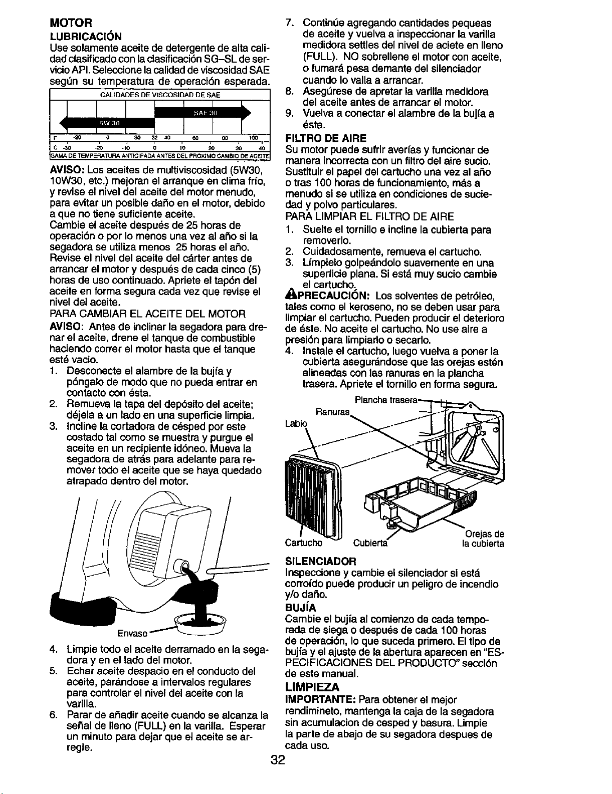
MOTOR
LUBRICACI6N
Usesolamenteaceitededetergentedealtacali-
dadclasificadoconlaclasificaci6nSG-SLdeser-
vicioAPI.SeleccionelacalidaddeviscosidadSAE
segOn su temperatura de operaci6n esperada.
CALIDADES DE VISCOSIDAD DE SAE
AVISO: Los aceites de multiviscosidad (5W30,
10W30, etc.) mejoran el arranque en clima frfo,
y revise el nivel del aceite del motor menudo,
para evitar un posible dafio en el motor, debido
a que no tiene suficiente aceite.
Cambie el aceite despu_s de 25 horas de
operaci6n o por Io menos una vez al afio si la
segadora se utiliza menos 25 horas el afio.
Revise el nivel del aceite del cdrter antes de
arrancar el motor y despuds de cada cinco (5)
horas de uso continuado. Apriete el tap6n del
aceite en forma segura cada vez que revise el
nivel del aceite.
PARA CAMBIAR EL ACEITE DEL MOTOR
AMISO: Antes de inclinar la segadora para dre-
nat el aceite, drene el tanque de combustible
haciendo correr el motor hasta que el tanque
este vacio.
1. Desconecte el alambre de la bujfa y
p6ngalo de modo que no pueda entrar en
contacto con _sta.
2. Remueva la tapa del dep6sito del aceite;
dejela a un lado en una supefficie limpia.
3. Incline la cortadora de cesped por este
costado tal como se muestra y purgue el
aceite en un recipiente id6neo. Mueva la
segadora de atrds para adelante para re-
mover todo el aceite que se haya quedado
atrapado dentro del motor.
7. Continde agregando cantidades pequeas
de aceite y vuelva a inspeccionar la varilla
medidora settles del nivel de aciete en Ileno
(FULL). NO sobrellene el motor con aceite,
o fumard pesa demante del sUenciador
cuando Io valla a arrancar.
8. Aseg_rese de apretar la varilla medidora
del aceite antes de arrancar el motor.
9. Vuelva a conectar el alambre de la bujfa a
esta.
FILTRO DE AIRE
Su motor puede sufrir averfas y funcionar de
manera incorrecta con un filtro del airs sucio.
Sustituir el papel del cartucho una vez al afio
o tras 100 horas de funcionamiento, rods a
menudo si se utiliza en condiciones de sucie-
dad y polvo particulates.
PARA LIMPIAR EL FILTRO DE AIRE
1. Suelte el tornillo e incline la cubierta para
removerlo.
2. Cuidadosamente, remueva el cartucho.
3. Lfmpielo golpedndolo suavemente en una
superficie plana. Si estd muy sucio cambie
el cartucho;
_LPRECAUOION: Los solventes de petr61eo,
tales como el keroseno, no se deben usar para
limpiar el cartucho. Pueden producir el deterioro
de dste. No aceite el cartucho. No use aire a
presi6n para limpiarlo o secarlo.
4. Instale el cartucho, luego vuelva a poner la
cubierta asegurdndose que las orejas estdn
alineadas con las ranuras en la plancha
trasera. Apdete el tornillo en forma segura.
Ranuras
Labio
Envase
4. Limpie todo el aceite derramado en la sega-
dora yen el lado del motor.
5. Echar aceite despacio en el conducto del
aceite, pardndose a intervalos regulares
para controlar el nivel del aceite con la
varilla.
6. Parar de afiadir aceite cuando se alcanza la
serial de Ileno (FULL) en la varilla. Esperar
un minuto para dejar que el aceite se ar-
regle.
Or_as de
Cartucho la cubierta
SILENClADOR
Inspeccione y cambie el sUenciador si estd.
corroido puede producir un peligro de incendio
y/o dafio.
BUJ[A
Cambie el bujia al comienzo de cada tempo-
rada de siega o despu_s de cada 100 horas
de operaci6n, Io que suceda primero. El tipo de
bujfa y el ajuste de la abertura aparecen en "ES-
PECIFICACIONES DEL PRODUCTO" secci6n
de este manual.
LIMPIEZA
IMPORTANTE: Para obtener el mejor
rendimineto, mantenga la caja de la segadora
sin acumulacion de cesped y basura. Limpie
la parts de abajo de su segadora despues de
cada uso.
32
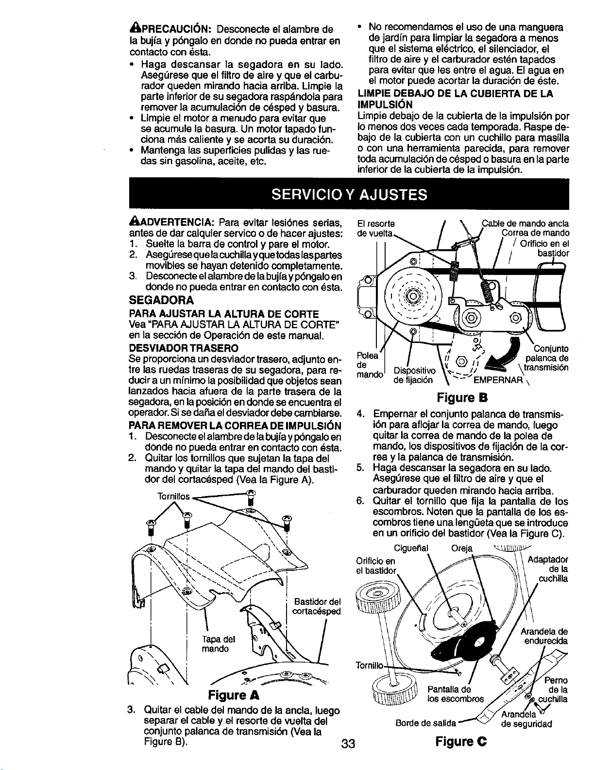
_I_PRECAUCI6N: Desconecte el alambre de
la bujfa y p6ngalo en donde no pueda entrar en
contacto con esta.
• Haga descansar la segadora en su lado.
Aseg_rese que el filtro de aire y que el carbu-
rador queden mirando haeia arriba. Limpie la
parte inferior de su segadora raspdndola para
remover la acumulaci6n de cesped y basura.
• Limpie el motor a menudo para evitar que
se acumule la basura. Un motor tapado fun-
ciona mas caliente y se acorta su duraci6n.
• Mantenga las superficies pulidas y las rue-
das sin gasolina, aceite, etc.
• No recomendamos el uso de una manguera
de jardfn para limpiar la segadora a menos
que el sistema el_ctrico, el silenciador, el
filtro de airs y el carburador est_n tapados
para evitar que les entre el agua. El agua en
el motor puede acortar la duraci6n de _ste.
LIMPIE DEBAJO DE LA CUBIERTA DE LA
IMPULSION
Limpie debajo de la cubierta de la impulsi6n por
Io menos dos veces cada temporada. Rasps de-
bajo de la cubierta con un cuchillo para masilla
o con una herramienta parecida, para remover
toda acumulacibn de c_sped o basura en la parte
inferior de la cubierta de la impulsi6n.
_,ADVERTENClA: Para evitar lesi6nes serias,
antes de dar calquier servico o de hacer ajustes:
1. Suelte la barra de control y pare el motor.
2. Aseg_reseque lacuchilla yquetodas laspartes
movibles se hayan detenido completamente.
3. Desconecte elalambre de la bujfayp6ngalo en
donde no pueda entrar en contacto con Osta.
SEGADORA
PARA AJUSTAR LA ALTURA DE CORTE
Vea =PARA AJUSTAR LA ALTURA DE CORTE"
en la secci6n de Operaci6n de este manual.
DESVIADOR TRASERO
Se proporciona un desviador trasero, adjunto en-
tre las ruedas traseras de su segadora, para re-
ducir a un mfnimo la posibilidad que objetos sean
lanzados hacia afuera de la parte trasera de la
segadora, en laposici6n en donde se encuentra el
operador.Si se dafia eldesviador debe cambiarse.
PARA REMOVER LA CORREA DE IMPULSION
1. Desconecte elalambre de la bujfay pbngalo en
donde no pueda entrar en contacto con _sta.
2. Quitar los tornUlos que sujetan la tapa del
mando y quitar la tapa del mando del basU-
dor del cortac_sped (Vea la Figure A).
Tornillos
' Bastidordel
cortac_sped
Tapa del
mando
Figure A
3. Quitar el cable del mando de la ancla, luego
separar el cable y el resorte de vuelta del
conjunto palanca de transmisi6n (Vea la
Figure B). 33
El resorts /
/ /'.--.', \
___ '-':_-:2" z
1 1
Pol
de .I r3i_lnn_itivn _t
Cablede mandoancla
t Correa de mando
/ / Orificio enel
/ bastidor
Oon'"o'o
I, _ palancade
'_'//' _ \transmisi6n
'--_--_/EMPERNAR'\
Figure IB
4. Empernar el conjunto palanca de transmis-
i6n para aflojar la correa de mando, luego
quitar la correa de mando de la polea de
mando, los dispositivos de fijaci6n de la cor-
rea y la palanca de transmisi6n.
5. Haga descansar la segadora en su lado.
Aseg_rese que el filtro de airs y que el
carburador queden mirando hacia arriba.
6. Quitar el tornillo que fija la pantalla de los
escombros. Noten que la pantalla de los es-
combros tiene una lengOeta que se introduce
en un orificio del bastidor (Vea la Figure C).
Ciguefial Oreja
Orificio en Adaptador
el bastidor de la
cuchilla
Arandela de
endurecida
los escombros
Perno
de la
cuchilla
Bordede salida de seguridad
Figure ¢
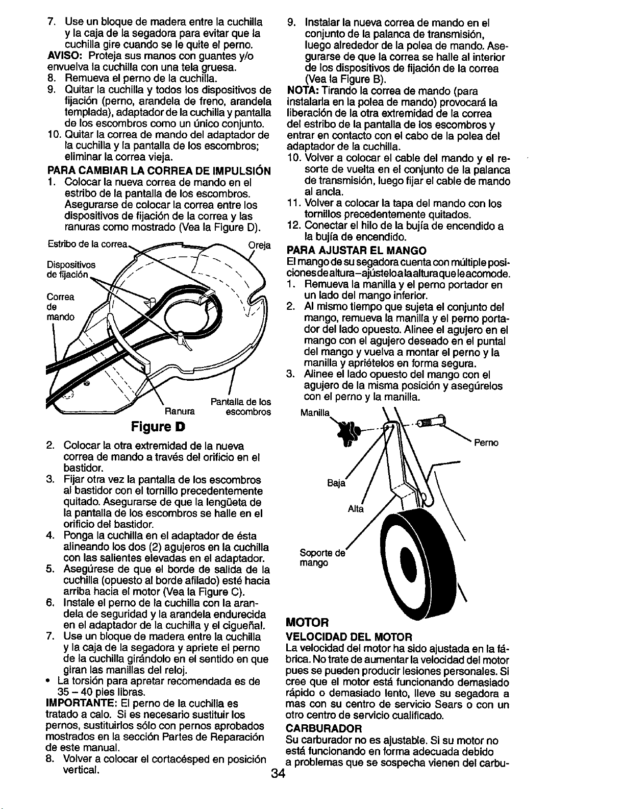
7. Use un bloque de madera entre la cuchiUa
y la caja de la segadora para evitar que la
cuchilla gire cuando se le quite el perno.
AVISO" Proteja sus manos con guantes y/o
envuelva la cuchUla con una tela gruesa.
8. Remueva el perno de la cuchilla.
9. Quitar la euchilla y todos los dispositivos de
fijaci6n (perno, arandela de freno, arandela
templada), adaptador de la cuchilla y pantalla
de los escombros como un I_nico conjunto.
10. Quitar la correa de mando del adaptador de
la cuchilla y la pantalla de los escombros;
eliminar la correa vieja.
PARA CAMBIAR LA CORREA DE IMPULSI(_N
1. Colocar la nueva correa de mando en el
estribo de la pantalla de los escombros.
Asegurarse de colocar la correa entre los
dispositivos de fijaci6n de la correa y las
ranuras como mostrado (Vea la Figure D).
Estribo de la correa,
_reja
Dispositivos
de f
Correa
de
mando
Pantallade los
Ranura escombros
Figure D
2. Colocar la otra extremidad de la nueva
correa de mando a tray,s del orificio en el
bastidor.
3. Fijar otra vez la pantalla de los escombros
al bastidor con el tornillo precedentemente
quitado. Asegurarse de que la lengQeta de
la pantalla de los escombros se halle en el
orificio del bastidor.
4. Ponga la cuchilla en el adaptador de dsta
alineando los dos (2) agujeros en la cuchilla
con las salientes elevadas en el adaptador.
5. Aseg_rsse de que el borde de salida de la
cuchilla (opuesto al borde afilado) este hacia
arriba hacia el motor (Vea la Figure C).
6. Instale el perno de la cuchilla con la aran-
dela de seguridad y la arandela endurecida
en el adaptador de la cuchilla y el eiguei_al.
7. Use un bloque de madera entre la cuchilla
y la caja de la segadora y apriete el perno
de la cuchilla girdndolo en el sentido en que
giran las manillas del reloj.
• La torsi6n para apretar recomendada es de
35 - 40 pies libras.
IMPORTANTE: El perno de la euchilla es
tratado a calo. Si es necesario sustituir los
pernos, sustituirlos s61o con pernos aprobados
mostrados en la secci6n Partes de Reparaci6n
de este manual.
8. Volver a colocar el cortac_sped en posici6n
vertical.
9. Instalar la nueva correa de mando en el
conjunto de la palanca de transmisi6n,
luego alrededor de la polea de mando. Ase-
gurarse de que la correa se halle al interior
de los dispositivos de fijaci6n de la correa
(Vea la Figure B).
NOTA: Tirando la correa de mando (para
instalarla en la polea de mando) provocard la
liberaci6n de la otra extremidad de la correa
del estribo de la pantalla de los escombros y
entrar en contacto con el cabo de la polea del
adaptador de la cuchilla.
10. Volver a colocar el cable del mando y el re-
sorte de vuelta en el conjunto de la palanca
de transmisi6n, luego fijar el cable de mando
al ancla.
11. Volver a colocar la tapa del mando con los
tornillos precedentemente quitados.
12. Conectar el hilo de la buj{a de encendido a
la bujfa de encendido.
PARA AJUSTAR EL MANGO
El mango desu segadora cuenta con mdltiple posi-
cionesde altura-aj_Jsteloalaalturaqueleacomode.
1. Remueva la manilla y el perno portador en
un lado del mango inferior.
2. AI mismo tiempo que sujeta el conjunto del
mango, remueva la manilla y el perno porta-
dor del lado opuesto. Alinee el agujero en el
mango con el agujero deseado en el puntal
del mango y vuelva a montar el perno y la
manilla y aprietelos en forma segura.
3. Alinee el lado opuesto del mango con el
agujem de la misma posici6n y aseg_Jrelos
con el perno y la manilla.
Manilla
- _ Perno
Alia
Sopo_e
mango
MOTOR
VELOCIDAD DEL MOTOR
La velocidad del motor ha sido ajustada en la f_-
brica. No trate de aumentar la velocidad del motor
pues se pueden producir lesiones personales. Si
cree que el motor est_ funcionando demasiado
r&pido o demasiado lento, Ileve su segadora a
mas con su centro de servicio Sears o con un
otro centro de servicio cualificado.
CARBURADOR
Su carburador no es ajustable. Si su motor no
estd funcionando en forma adecuada debido
a problemas que se sospecha vienen del carbu-
34
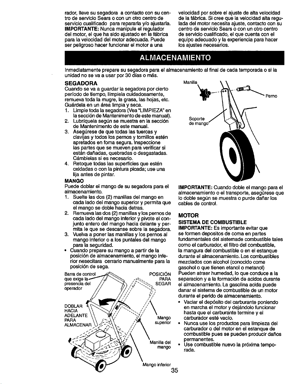
rador,Ileve su segadora a contacto con su cen-
tro de servicio Sears o con un otro centro de
servicio cualificado para repararla y/o ajustada.
IMPORTANTE" Nunca manipule el regulador
del motor, el que ha sido ajustado en la f&brica
para la velocidad del motor adecuada. Puede
ser peligroso hacer funcionar el motor a una
velocidad por sobre el ajuste de alta velocidad
de la f&brica. Si cree que la velocidad alta regu-
lada del motor necesita ajuste, contacto con su
centro de servicio Sears o con un otro centro
de servicio cualificado, el que cuenta con el
equipo adecuado y la experiencia para hacer
los ajustes necesarios.
Inmediatamente prepare su segadora para el almacenamiento al final de cada temporada o si la
unidad no se va a usar por 30 dias o mds.
SEGADORA Manilta
Cuando se va a guardar la segadora por cierto
pedodo de tiempo, Ifmpiela cuidadosamente,
remueva toda la mugre, la grasa, las hojas, etc.
Gudrdela en un drea limpia y seca.
1. Limpie toda la segadora (Vea "LIMPIEZA" en
lasecci6n de Mantenimento de este manual).
2. Lubrfquela segt_n se muestra sn la seccibn Soporte
de Mantenimento de este manual.
3. AsegL_rase de que todas las tuercas y
clavijas y todos los pernos y tornillos est_n
apretados en foma segura. Inspeccione
las partes que se mueven para verificar si
estdn dafiadas, quebradas o desgastadas.
Cambielas si es necesario.
4. Retoque todas las superficies que estdn
oxidadas o con la pintura picada; use una
lija antes de pintar.
MANGO
Puede doblar el mango de su segadora para el
almacenamiento.
1. Suelte las dos (2) manillas del mango en
cada lado del mango superior y permita que
el mango se doble hacia detras.
2. Remueva las dos (2) manillas y los pernos de MOTOR
cada lado del mango inferior y pivots el con-
junto entero del mango hacia delante y per-
mita le que se descanse sobre la segadora.
3. Vuelva a poner las manillas y los pernos al
mango inferior o a los puntales del mango
para la seguridad.
• Cuando prepare su mango a partir de la
posici6n de almacenamiento, el mango infe-
rior nesecitara cerrarlo manualmente para la
posici6n de sega.
Barra de control POSIClON
que exig PARA
presencia del SEGAR
operador
DOBLAR
HACIA
ADELANTE Mango
PARA
ALMACENAR superior
Manilladel
mango
--_ Perno
IMPORTANTE: Cuando doble el mango para el
almacenamiento o el transporte, asegerese que
Io doble segt_n se muestra o purde dafiar los
cables de control.
SISTEMA DE COMBUSTIBLE
IMPORTANTE: Es importante evitar que
se formen depositos de coma en partes
fundamentales del sistemade combustible tales
como el carburador, el filtro del combustible,
la mangura del combustible o en el estanque
durante el almacenamiento. Los combustibles
mezclados con alcohol (conocido come
gasohol o que tienen etanol o metanol)
Pueden atraer humedad, Io que conduce a la
separacion y a la formaci6n de acidos durante
el almacenamiento. La gasolina acida puede
danar el sistema de combustible de un motor
durante el perido de almacenamiento.
• Vaciar el dep6sito del carburante poniendo
en marcha el motor y dejandolo funcionar
hasta que el carburante terrains y el
carburador est_ vacfo.
• Nunca use los productos para limpieza del
carburador o del motor en el estanque de
combustible pues se pueden producir dafios
permanentes.
• Use combustible nuevo la pr6xima tempo-
rada.
Mango inferior
35
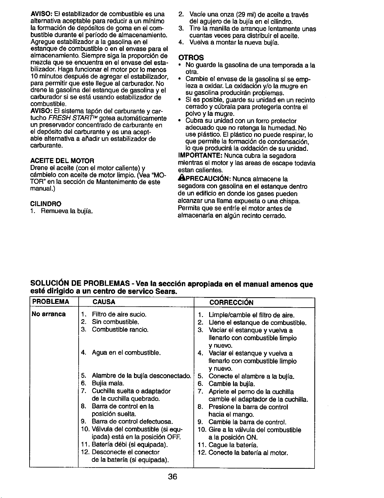
AVISO" El estabilizador de combustible es una
alternativa aceptable para reducir a un mfnimo
la formaci6n de dep6sitos de goma en el com-
bustible durante el perfodo de almacenamiento.
Agregue estabilizador a la gasolina en el
estanque de combustible o en el envase para el
almacenamiento. Siempre siga la pmpomi6n de
mezcla que se encuentra en el envase del esta-
bilizador. Haga funcionar el motor por Io menos
10 minutos despu_s de agregar el estabilizador,
para permitir que este Ilegue al carburador. No
drene la gasolina del estanque de gasolina y el
carburador si se est_ usando estabilizador de
combustible.
AVISO: El sistema tap6n del carburante y car-
tucho FRESH START TM gotea autom&ticamente
un preservador concentrado de carburante en
el dep6sito del carburante y es una acept-
able alternativa a aSadir un estabilizador de
carburante.
ACEITE DEL MOTOR
Drene el aceite (con el motor caliente) y
cdmbielo con aceite de motor limpio. (Vea "MO-
TOR" en la secci6n de Mantenimento de este
manual.)
ClLINDRO
1. Remueva la bujfa.
2. Vacfe una onza (29 ml) de 8ceite a travds
del agujero de la bujfa en el cilindro.
3. Tire la manilla de arranque lentamente unas
cuantas veces para distribuir el aceite.
4. Vuelva a montar la nueva bujfa.
OTROS
• No guarde la gasolina de una temporada a la
otra.
• Cambie el envase de la gasolina si se emp-
ieza a oxidar. La oxidaci6n y/o la mugre en
su gasolina producirdn problemas.
• Si es posible, guarde su unidad en un recinto
cerrado y cObrala para protegerla contra el
polvo y la mugre.
• Cubra su unidad con un forro protector
adecuado que no retenga la humedad. No
use pl._stico.El pldstico no puede respirar, Io
que permite la formaci6n de condensaci6n,
Io que producir8 la oxidaci6n de su unidad.
IMPORTANTE." Nunca cobra la segadora
mientras el motor y las areas de escape todavia
estan calientes.
_I=PRECAUCl6N" Nunca almacene la
segadora con gasolina en el estanque dentro
de un edificio en donde los gases pueden
alcanzar una llama expuesta o una chispa.
Permita que se enfrfe el motor antes de
almacenarla en alg6n recinto cerrado.
SOLUCI(_N DE PROBLEMAS - Vea la seccidn apropiada en el manual amenos que
estd dirigido a un centro de servico Sears.
PROBLEMA
No arrsnca
CAUSA CORRECCION
1. FiRm de aire sucio.
2. Sin combustible.
3. Combustible rancio.
4. Agua en el combustible.
5. Alambre de la bujfa desconectado.
6. Bujia mala.
7. Cuchilla suelta o adaptador
de la cuchilla quebrado.
8. Barra de control en la
posici6n suelta.
9. Barra de control defectuosa.
10. Vdlvula del combustible (si equ-
ipada) estd en la posici6n OFF.
11. Baterfa debi (si equipada).
12. Desconecte el conector
de la baterfa (si equipada).
1. Limpie/cambie el filtro de aim.
2. Llene el estanque de combustible.
3. Vaciar el estanque y vuelva a
Ilenarlo con combustible limpio
y nuevo.
4. Vaciar el estanque y vuelva a
Ilenarlo con combustible limpio
y nuevo.
5. Conecte el alambre a la bujfa.
6. Cambie la bujia.
7. Apriete el perno de la cuchilla
cambie el adaptador de la cuchilla.
8. Presione la barra de control
hacia el mango.
9. Cambie la barra de control.
10. Gire a la valvula del combustible
a la posici6n ON.
11. Cague la baterfs.
12. Conecte 18baterfa al motor.
36
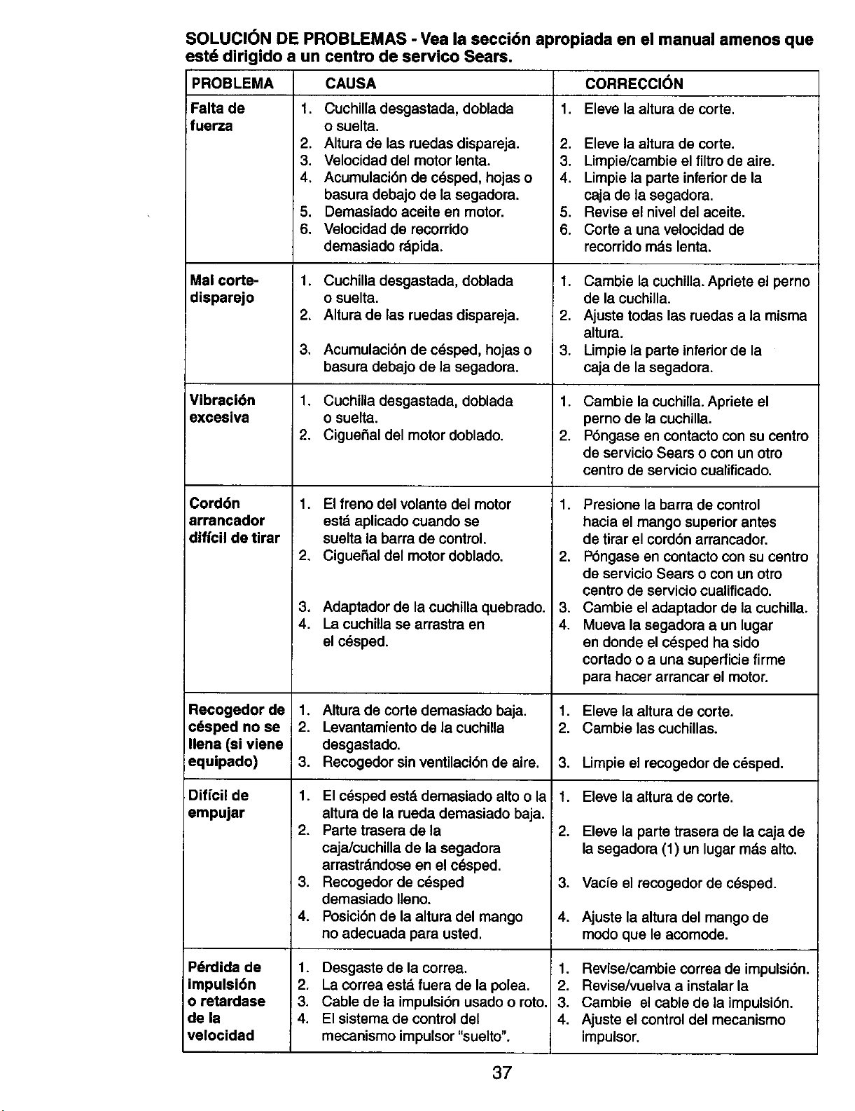
SOLUCI6N DE PROBLEMAS - Vea la secci6n apropiada en el manual amenos que
estd dirigido a un centro de servico Sears.
PROBLEMA
Falta de
fuerza
Mal corte-
disparejo
Vibraci6n
excesiva
Cord6n
arrancador
diffcil de tirar
Recogedor de
c6sped no se
Ilena (si viene
equipado)
Diffcil de
empujar
Pdrdida de
impulsi6n
o retardase
de la
velocidad
CAUSA CORRECCION
1. 1. Eleve la altura de corte.
Cuchilla desgastada, doblada
o suelta.
2. Altura de las ruedas dispareja.
3. Veloeidad del motor lenta.
4. Acumulaci6n de crisped, hojas o
basura debajo de la segadora.
5. Demasiado aceite en motor.
6. Velocidad de recorrido
demasiado rdpida.
1. Cuchilla desgastada, doblada
o suelta.
2. Altura de las ruedas dispareja.
3, Acumulaci6n de crisped, hojas o
basura debajo de la segadora.
1. Cuchilla desgastada, doblada
o suelta.
2. Ciguefial del motor doblado.
1. El freno del volante del motor
estd aplicado cuando se
suelta la barra de control,
2. Ciguefial del motor doblado.
3. Adaptador de la cuchilla quebrado.
4. La cuchilla se arrastra en
el c_sped.
1. Altura de corte demasiado baja.
2. Levantamiento de la cuchilla
desgastado.
3. Recogedor sin ventilaci6n de aire.
1. El c_sped estd demasiado alto o la
altura de la rueda demasiado baja.
2. Parle trasera de la
caja/cuchilla de la segadora
arrastrdndose en el edsped.
3. Recogedor de c_sped
demasiado Ileno.
4. Posici6n de la altura del mango
no adecuada para usted.
1. Desgaste de la correa.
2. La correa estd fuera de la polea.
3. Cable de la impulsi6n usado o roto.
4. El sistema de control del
mecanismo impulsor "suelto".
2. Eleve la altura de corte.
3. Limpie/cambie el filtro de aire.
4. Limpie la parte inferior de la
caja de la segadora.
5. Revise el nivel del aceite.
6. Corte a una velocidad de
recorrido mds lenta.
1. Cambie la cuchilla. Apriete el perno
de la cuchilla.
2. Ajuste todas las ruedas a la misma
altura.
3. Limpie la parte inferior de la
caja de la segadora.
1. Cambie la cuchilla. Apriete el
perno de la cuchilla.
2. P6ngase en contacto con su centro
de servicio Sears o con un otro
centro de servicio cualificado.
1. Presione la barra de control
hacia el mango superior antes
de tirar el cord6n arrancador.
2. P6ngase en contacto con su centro
de servicio Sears o con un otro
centro de servicio cualificado.
3, Cambie el adaptador de la cuchilla.
4. Mueva la segadora a un lugar
en donde el c_sped ha sido
cortado o a una superficie firme
para hacer arrancar el motor.
1. Eleve la altura de corte.
2. Cambie las cuchiUas.
3. Limpie el recogedor de cdsped.
1. Eleve la altura de corte.
2. Eleve la parte trasera de la caja de
la segadora (1) un lugar mds alto.
3. Vacfe el racogedor de c_sped.
4. Ajuste la altura del mango de
modo que le acomode.
1. Revise/cambie correa de impulsi6n.
2. Revise/vuelva a instalar la
3. Cambie el cable de la impulsi6n.
4. Ajuste el control del mecanismo
impulsor.
37
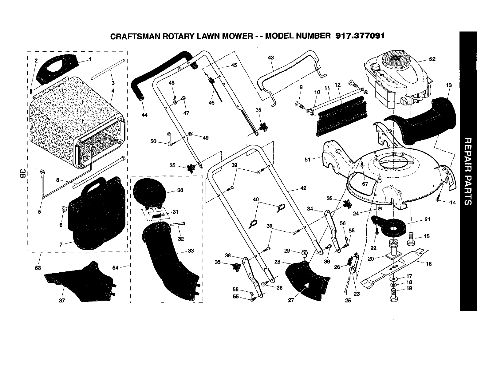
CRAFTSMAN ROTARY LAWN MOWER - - MODEL NUMBER 917.377091
2
53
37
43
44 47
32
46
35
4O
39
27
12
56
36
25
23
13
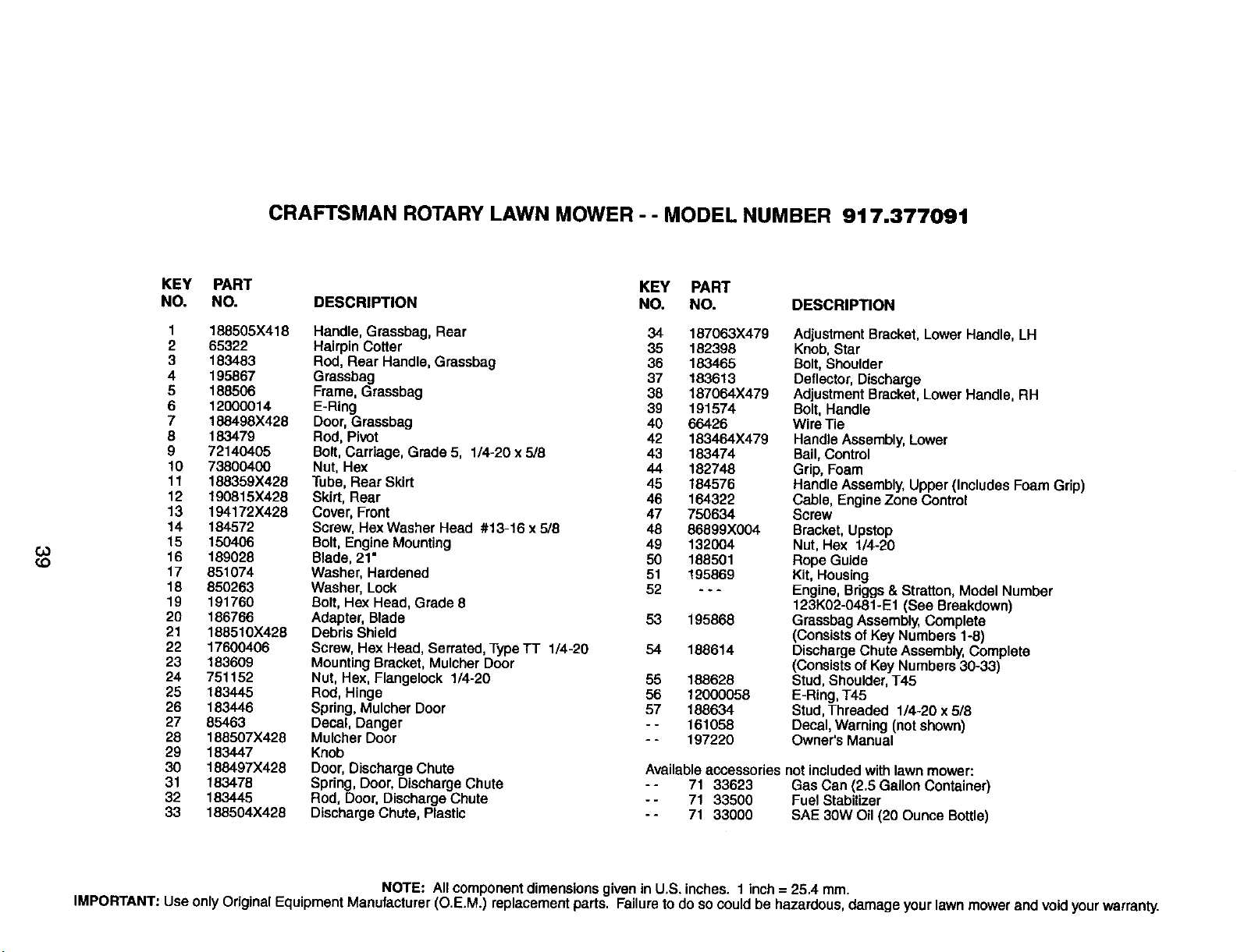
CRAFTSMAN ROTARY LAWN MOWER - - MODEL NUMBER 917.377091
Go
_D
KEY PART KEY PART
NO. NO. DESCRIPTION NO. NO. DESCRIPTION
1 188505X418 Handle, Grassbag, Rear 34 187063X479
2 65322 Hairpin Cotter 35 182398
3 183483 Rod, Rear Handle, Grassbag 36 183465
4 195867 Grassbag 37 183613
5 188506 Frame, Grassbag 38 187064X479
6 12000014 E-Ring 39 191574
7 188498X428 Door, Grassbag 40 66426
8 183479 Rod, Pivot 42 183464X479
9 72140405 Bolt, Carriage, Grade 5, 1/4-20 x 5/8 43 183474
10 73800400 Nut, Hex 44 182748
11 188359X428 Tube, Rear Skirt 45 184576
12 190815X428 Skirt, Rear 46 164322
13 194172)(428 Cover, Front 47 750634
14 184572 Screw, Hex Washer Head #13-16 x 5/8 48 86899X004
15 150406 Bolt, Engine Mounting 49 132004
16 189028 Blade, 21" 50 188501
17 851074 Washer, Hardened 51 195869
18 650263 Washer, Lock 52 - - -
19 191760 Bolt, Hex Head, Grade 8
20 186766 Adapter, Blade 53 195868
21 188510X428 Debris Shield
22 17600406 Screw, Hex Head, Serrated, Type TT 1/4-20 54 188614
23 183609 Mounting Bracket, Mulcher Door
24 751152 Nut, Hex, Flangelock 1/4-20 55 188628
25 183445 Rod, Hinge 56 12000058
26 183446 Spring, Mulcher Door 57 188634
27 85463 Decal, Danger - - 161058
28 188507X428 Mulcher Door - - 197220
29 183447 Knob
30 188497X428 Door, Discharge Chute
31 183478 Spring, Door, Discharge Chute
32 183445 Rod, Door, Discharge Chute
33 188504X428 Discharge Chute, Plastic
AdjustmentBracket,LowerHandle, LH
Knob,Star
Bolt,Shoulder
Deflector,Discharge
Adjustment Bracket,LowerHandle,RH
Bolt,Handle
WiraTie
HandleAssembly,Lower
Bail,Control
Grip, Foam
HandleAssembly,Upper(IncludesFoamGrip)
Cable, Engine Zone Control
Screw
Bracket,Upstop
Nut, Hex 1/4-20
RopeGuide
Kit, Housing
Engine,Briggs& Stratton,ModelNumber
123K02-0481°E1 (See Breakdown)
GrassbagAssembly,Complete
(ConsistsofKeyNumbers1-8)
Discharge Chute Assembly,Complete
(ConsistsofKeyNumbers30-33)
Stud,Shoulder,T45
E-Ring,145
Stud,Thraaded 1/4-20 x 5/8
Decal,Warning(notshown)
Owner's Manual
Available accessories not included with lawn mower:
- - 71 33623 Gas Can (2.8 Gallon Container)
- - 71 33500 Fuel Stabilizer
- - 71 33000 SAE 30W Oil (20 Ounce Bottle)
NOTE: All component dimensions given in U,S. inches. 1 inch = 25,4 mm.
IMPORTANT: Use only Original Equipment Manufacturer (O.E.M.) replacement parts. Failure to do so could be hazardous, damage your lawn mower and void yourwarranty.
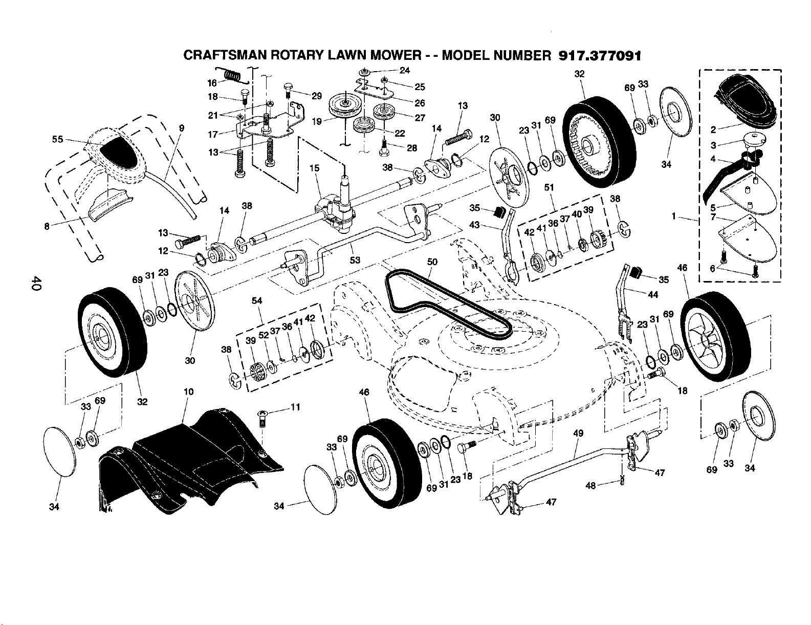
J_
o
\
f
34
32
CRAFTSMAN ROTARY LAWN MOWER - - MODEL NUMBER 917.377091
16
18_
9
3O
10
14
38
38
I
69
33
13
14
30
12
32
69 3
\
\
\
46
34
46
18
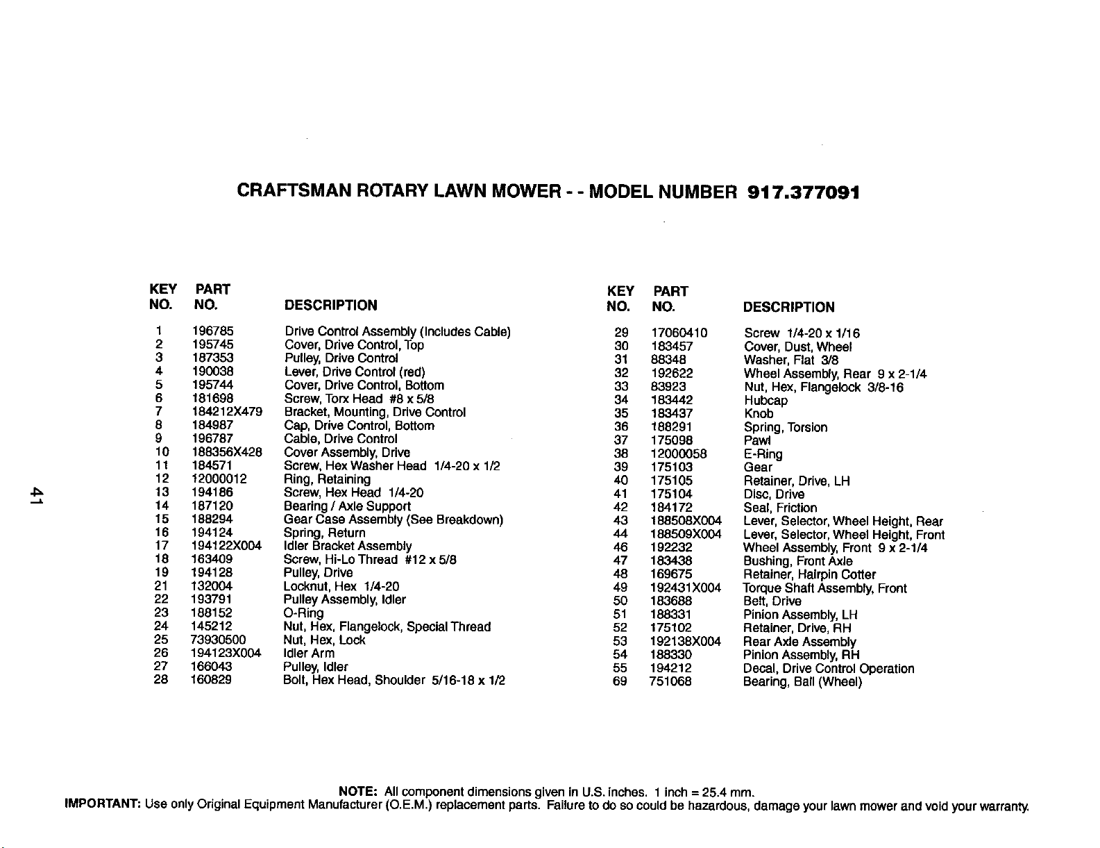
CRAFTSMAN ROTARY LAWN MOWER - - MODEL NUMBER 917.377091
KEY PART KEY PART
NO. NO, DESCRIPTION NO. NO. DESCRIPTION
1 196785 Drive Control Assembly (Includes Cable) 29 17060410 Screw 1/4-20 x 1/16
2 195745 Cover, Drive Control, Top 30 183457 Cover, Dust, Wheel
3 187353 Pulley, Drive Control 31 88346 Washer, Flat 3/8
4 190038 Lever, Drive Control (red) 32 192622 Wheel Assembly, Rear 9 x 2-1/4
5 195744 Cover, Drive Control, Bottom 33 83923 Nut, Hex, Flangelook 3/8-16
6 181698 Screw, Torx Head #8 x 5/8 34 183442 Hubcap
7 184212X479 Bracket, Mounting, Drive Control 35 183437 Knob
6 184987 Cap, Drive Control, Bottom 36 168291 Spring, Torsion
9 196787 Cable, Drive Control 37 175098 Pawl
10 188356)(428 Cover Assembly, Drive 38 12000058 E-Ring
11 164571 Screw, HexWasher Head 1/4-20 x 1/2 39 175103 Gear
12 12000012 Ring, Retaining 40 175105 Retainer, Drive, LH
13 194186 Screw, Hex Head 1/4-20 41 175104 Disc, Drive
14 187120 Bearing / Axle Support 42 184172 Seal, Friction
15 188294 Gear Case Assembly (See Breakdown) 43 188508X004 Lever, Selector, Wheel Height, Rear
16 194124 Spring, Return 44 188509X004 Lever, Selector, Wheel Height, Front
17 194122X004 Idler Bracket Assembly 46 192232 Wheel Assembly, Front 9 x 2-1/4
18 163409 Scraw, Hi-Lo Thread #12 x 5/8 47 183438 Bushing, Front AXle
19 194128 Pulley, Drive 48 169675 Retainer, Hairpin Cotter
21 132004 Lecknut, Hex 1/4-20 49 192431X004 Torque Shaft Assembly, Front
22 193791 Pulley Assembly, Idler 50 183688 Belt, Drive
23 188152 O-Ring 51 188331 Pinion Assembly, LH
24 145212 Nut, Hex, Flangeleck, Special Thread 52 175102 Retainer, Drive, RH
25 73930500 Nut, Hex, Lock 53 192138X004 Rear Axle Assembly
26 194123X004 Idler Arm 54 188330 Pinion Assembly, RH
27 166043 Pulley, Idler 55 194212 Decal, Drive Control Operation
28 160829 Bolt, Hex Head, Shoulder 5/16-18 x 1/2 69 751068 Bearing, Ball (Wheel)
NOTE; All component dimensions given in U.S. inches. 1 inch = 25.4 mm.
IMPORTANT; Use only Original Equipment Manufacturer (O.E.M.) replacement parts. Failure to do so could be hazardous, damage your lawn mower and void your warranty.
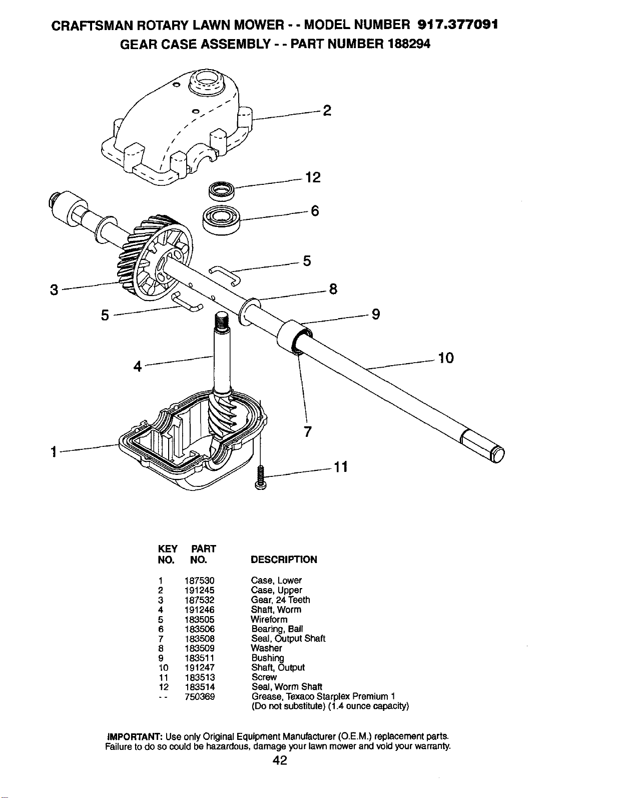
CRAFTSMAN ROTARY LAWN MOWER - - MODEL NUMBER 917.377091
GEAR CASE ASSEMBLY - - PART NUMBER 188294
2
3
1
5
4
5
7
9
10
KEY PART
NO. NO. DESCRIPTION
1 187530 Case, Lower
2 191245 Case, Upper
3 187532 Gear, 24 Teeth
4 191246 Shaft,Worm
5 183505 Wireform
6 183506 Bearing, Ball
7 183508 Seal, Output Shaft
8 183509 Washer
9 183511 Bushing
10 191247 Shaft, Output
11 183513 Screw
12 183514 Seal,Worm Shaft
- - 750369 Grease, TexacoStarplex Premium 1
(Do not substitute)(1.4 ounce capacity)
IMPORTANT: UseonlyOriginalEquipmentManufacturer(O.E.M.) replacementparts.
Failuretodoso couldbe hazardous,damageyourlawnmowerandvoid yourwarranty.
42
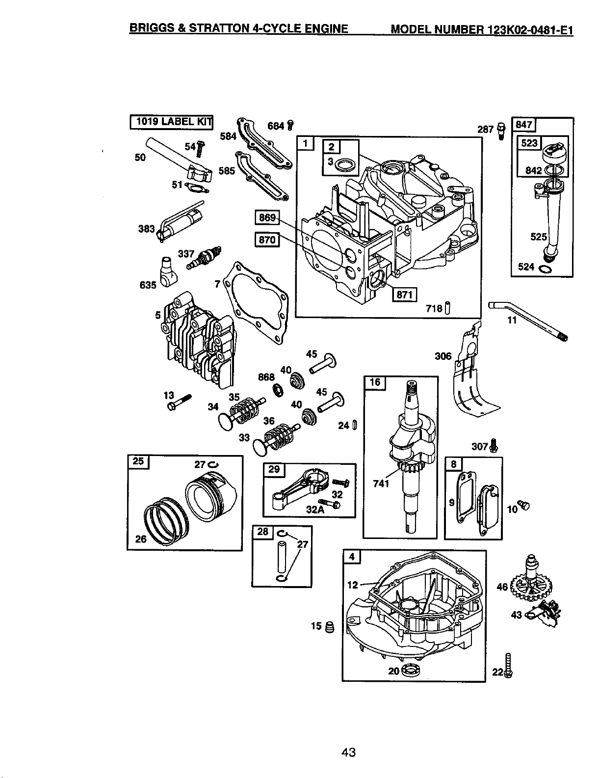
BRIGGS & STRATTON 4-CYCLE ENGINE MODEL NUMBER 123K02-0481-E1
[ 1019 LABEL KIll
27C,
525
2o_
22i
43
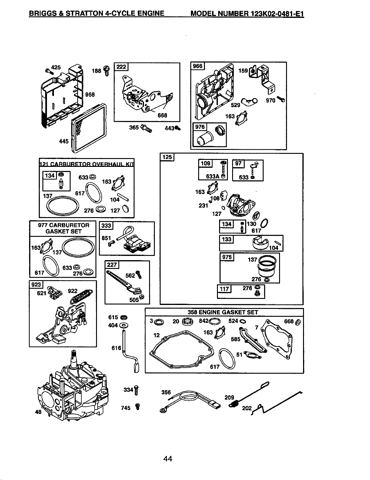
BRIGGS & STRA'rI'ON 4-CYCLE ENGINE MODEL NUMBER 123K02-0481-E1
445
968
668
365 _ 443411,,
I:)1 CARBtlRI=TNR OVFRHAIIL KI_
633_ 163
_-_ 617_
977 CARBURETOR
GASKET SET
7_633_
61 276_
° 1
505 _
127
617
t_ ®,o4_1
48
334_
745_
356
44
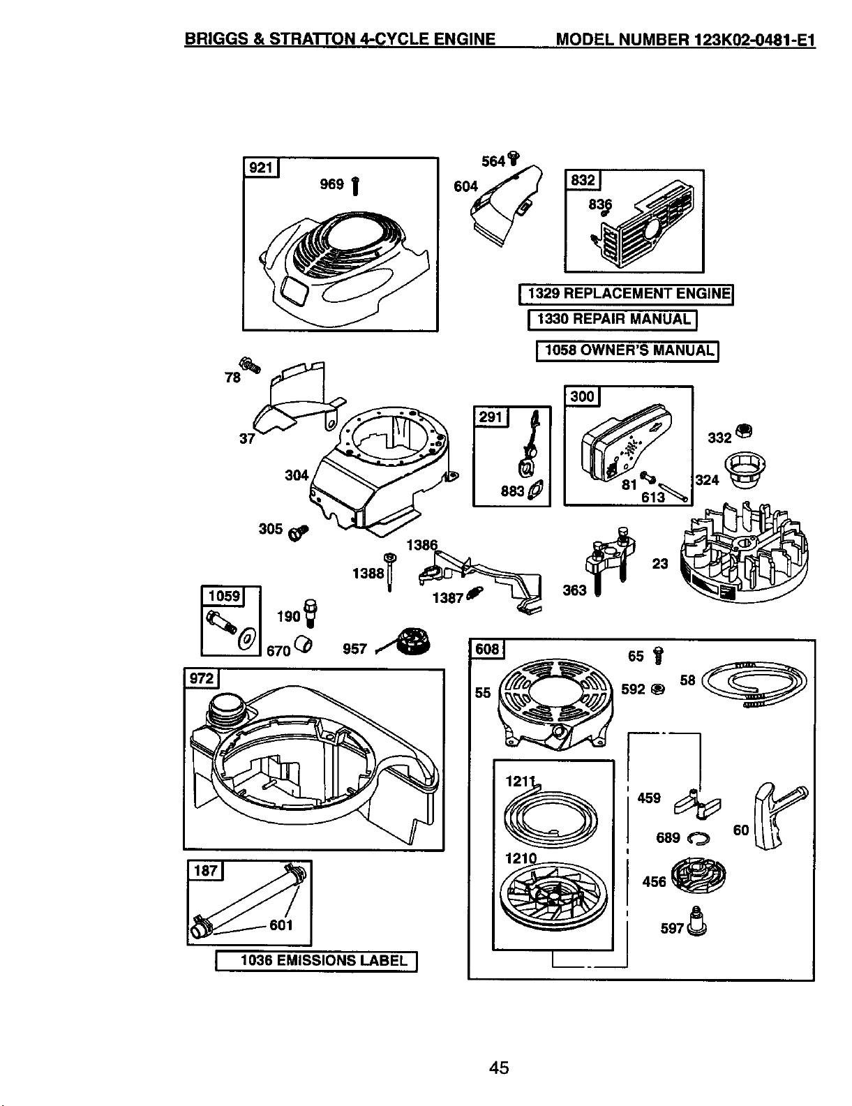
BRIGGS & STRATrON 4-CYCLE ENGINE MODEL NUMBER 123K02-0481-E1
304
959I
564_
I 1329 REPLACEMENT ENGINE I
11330REPA,R.ANUA,I
I 1058 OWNER'S MANUAL I
13001 I
305
190_
670@ 957
1386 3_
L 1036 EMISSIONS LABEL J
55
65It
592 _ 58 L__._/
689 _ 60
456_
s97_
45
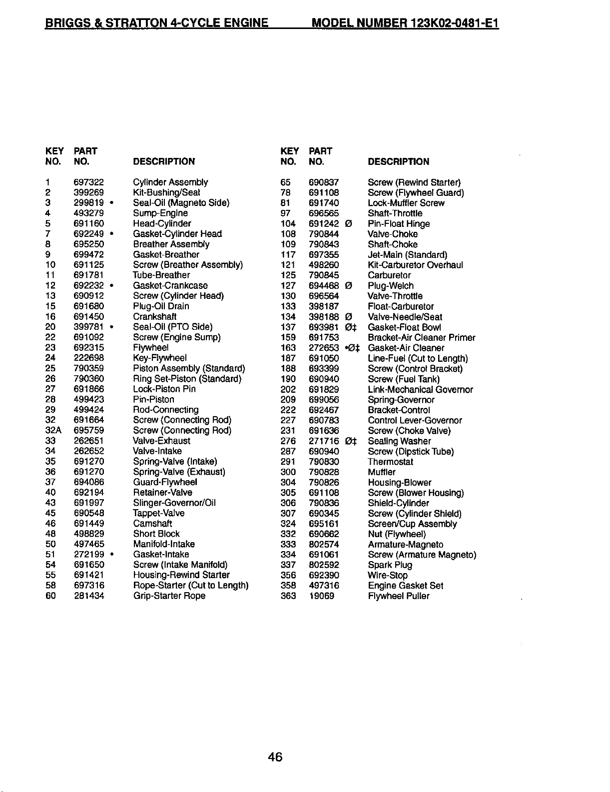
BRIGGS & STRA'I-rON 4-CYCLE ENGINE MODEL NUMBER 123K02-0481-E1
KEY PART
NO, NO, DESCRIPTION
1 697322 Cylinder Assembly
2 399269 Kit-Bushing/Seal
3 299819 • Seal-Oil (Magneto Side)
4 493279 Sump-Engine
5 691160 Head-Cylinder
7 692249 * Gasket-Cylinder Head
8 695250 Breather Assembly
9 699472 Gasket-Breather
10 691125 Screw (Breather Assembly)
11 691781 Tube-Breather
12 692232 • Gasket-Crankcase
13 690912 Screw (Cylinder Head)
15 691680 Plug-Oil Drain
16 691450 Crankshaft
20 399781 • Seal-Oil (PTO Side)
22 691092 Screw (Engine Sump)
23 692315 Flywheel
24 222698 Key-Flywheel
25 790359 Piston Assembly (Standard)
26 790360 Ring Set-Piston (Standard)
27 691866 Lock-Piston Pin
28 499423 Pin-Piston
29 499424 Rod-Connecting
32 691664 Screw (Connecting Rod)
32A 695759 Screw (Connecting Rod)
33 262651 Valve-Exhaust
34 262652 Valve-Intake
35 691270 Spring-Valve (Intake)
36 691270 Spring-Valve (Exhaust)
37 694086 Guard-Flywheel
40 692194 Retainer-Valve
43 691997 Slinger-Governor/Oil
45 690548 Tappet-Valve
46 691449 Camshaft
48 498829 Short Block
50 497465 Manifold-Intake
51 272199 * Gasket-Intake
54 691650 Screw (Intake Manifold)
55 691421 Housing-Rewind Starter
58 697316 Rope-Starter (Cut to Length)
60 281434 Grip-Starter Rope
KEY PART
NO. NO.
65 690837
78 691108
81 691740
97 696565
104 691242
108 790844
109 790843
117 697355
121 498260
125 790845
127 694468
130 696564
133 398187
134 398188
137 693981
159 691753
163 272653
187 691050
188 693399
190 690940
202 691829
209 699056
222 692467
227 690783
231 691636
276 271716
287 690940
291 790830
300 790828
304 790826
305 691108
306 790836
307 690345
324 695161
332 690662
333 802574
334 691061
337 802592
356 692390
358 497316
363 19069
DESCRIPTION
Screw(RewindStarter)
Screw(FlywheelGuard)
Lock-MufflerScrew
Shaft-Throttle
Pin-FloatHinge
Valve-Choke
Shaft-Choke
Jet-Main(Standard)
Kit-CarburetorOverhaul
Carburetor
I_ Plug-Welch
Valve-Throttle
Float-Carburetor
O Valve-Needle/Seat
£_:t Gasket-Float Bowl
Bracket-AirCleaner Primer
•O:1: Gasket-AirCleaner
Line-Fuel(Cutto Length)
Screw(ControlBracket)
Screw(FuelTank)
Link-MechanicalGovernor
Spring-Governor
Bracket-Control
ControlLever-Governor
Screw(ChokeValve)
la:l: SealingWasher
Screw(DipstickTube)
Thermostat
Muffler
Housing-Blower
Screw(BlowerHousing)
Shield-Cylinder
Screw (Cylinder Shield)
Screen/CupAssembly
Nut(Flywheel)
Armature-Magneto
Screw(ArmatureMagneto)
Spark Plug
Wire-Stop
EngineGasketSet
FlywheelPuller
46
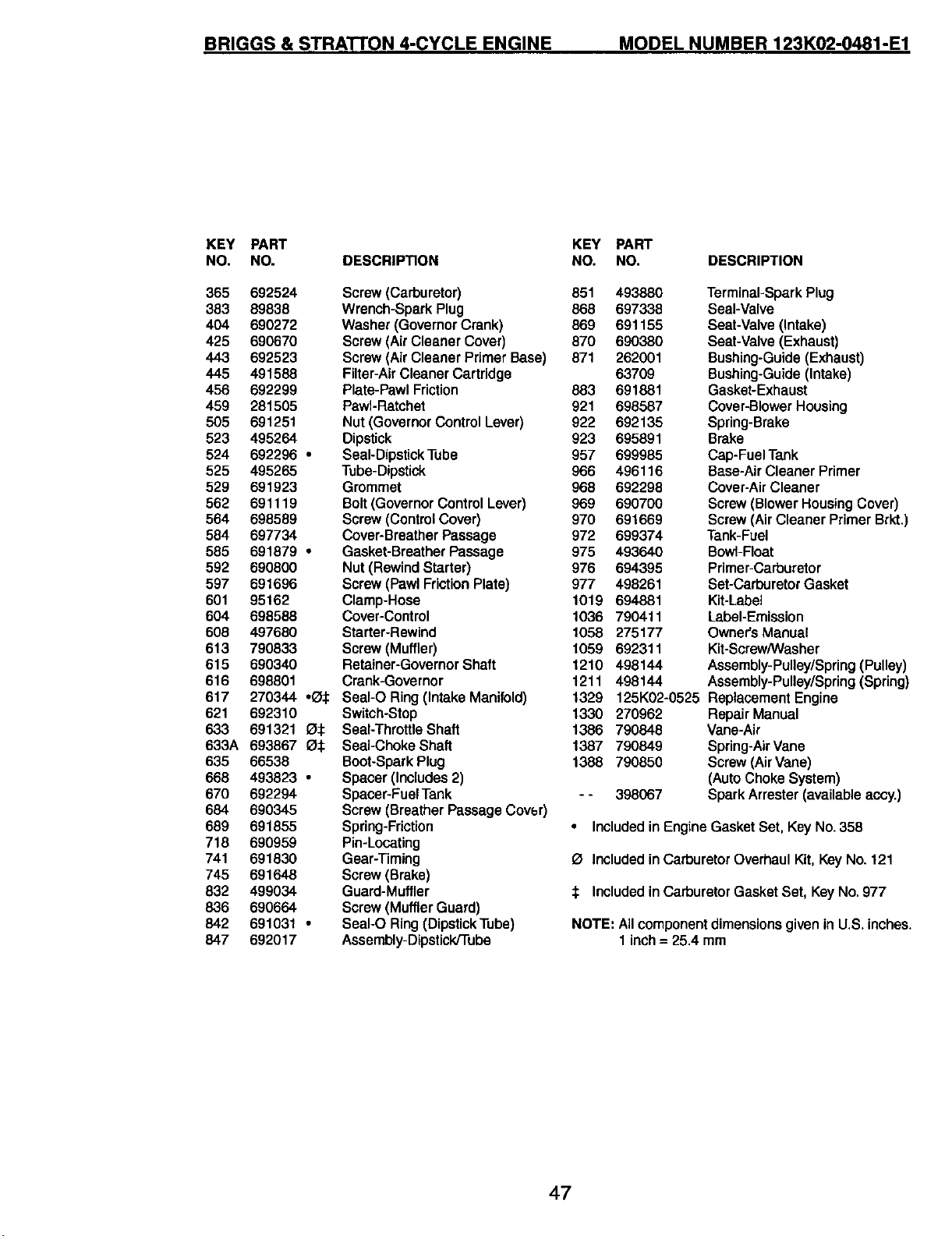
BRIGGS & STRATTON 4-CYCLE ENGINE MODEL NUMBER 123K02-0481-E1
KEY PART KEY PART
NO. NO. DESCRIPTION NO. NO.
365 692524 Screw (Carburetor) 851 493880
383 89838 Wrench-Spark Plug 868 697338
404 690272 Washer (Governor Crank) 869 691155
425 690670 Screw (Air Cleaner Cover) 870 690380
443 692523 Screw (Air Cleaner Primer Base) 871 262001
445 491588 Filter-Air Cleaner Cartridge 63709
456 692299 Plate-Pawl Friction 863 691881
459 281505 Pawl-Ratchet 921 698587
505 691251 Nut (Governor Control Lever) 922 692135
523 495264 Dipstick 923 695891
524 692296 • Seal-Dipstick Tube 957 699985
525 495265 Tube-Dipstick 966 496116
529 691923 Grommet 968 692298
562 691119 Bolt (Governor Control Lever) 969 690700
564 698589 Screw (Control Cover) 970 691669
584 697734 Cover-Breather Passage 972 699374
585 691879 • Gasket-Breather Passage 975 493640
592 690800 Nut (Rewind Starter) 976 694395
597 691696 Screw (Pawl Friction Plate) 977 498261
601 95162 Clamp-Hose 1019 694881
604 698588 Cover-Control 1036 790411
608 497680 Starter-Rewind 1058 275177
613 790833 Screw(Muffler) 1059 692311
615 690340 Retainer-Governor Shaft 1210 498144
616 698801 Crank-Governor 1211 498144
617 270344 "_:1: SeaI-O Ring (Intake Manifold) 1329
621 692310 Switch-Stop 1330
633 691321 O:1: Seal-Throttle Shaft 1386
633A 693867 O:1: Seal-Choke Shaft 1387
635 66538 Boot-Spark Plug 1388
668 493823 • Spacer (Includes 2)
670 692294 Spacer-Fuel Tank - -
684 690345 Screw (Breather Passage Cove,r)
689 691855 Spring-Friction
718 690959 Pin-Locating
741 691630 Gear-Timing
745 691648 Screw (Brake)
832 499034 Guard-Muffler
836 690664 Screw (Muffler Guard)
842 691031 • SeaI-O Ring (Dipstick Tube)
847 692017 Assembly-Dipstick/Tube
DESCRIPTION
Terminal-SparkPlug
Seal-Valve
Seat-Valve(Intake)
Seat-Valve (Exhaust)
Bushing-Guide (Exhaust)
Bushing-Guide (Intake)
Gasket-Exhaust
Cover-BlowerHousing
Spring-Brake
Brake
Cap-Fuel Tank
Base-Air Cleaner Primer
Cover-Air Cleaner
Screw (Blower Housing Cover)
Screw (Air Cleaner Primer Brkt.)
Tank-Fuel
Bowl-Float
Primer-Carburetor
Set-CarburetorGasket
Kit-Label
Label-Emission
Owner's Manual
Kit-Scraw/Washer
Assembly-Pulley/Spring (Pulley)
Assembly-Pulley/Spring (Spring)
125K02-0525 Replacement Engine
270962 Repair Manual
790848 Vane-Air
790849 Spring-AirVane
790850 Screw (Air Vane)
(AutoChokeSystem)
398067 Spark Arrester (available accy.)
• Included in Engine Gasket Set, Key No.358
O Included in Carburetor Overhaul Kit, Key No. 121
:1: Included inCarburetor Gasket Set, KeyNo.977
NOTE: All component dimensions given inU.S.inches.
1 inch =25.4 mm
47

ii_iliiiii_iii
!!i !!!iiiiii
i!iiiii_!i_i!iil
Your Home
For repair - in your home - of all major brand appliances,
lawn and garden equipment, or heating and cooling systems,
no matter who made it, no matter who sold it!
For the replacement parts, accessories and
owner's manuals that you need to do-it-yourself.
For Sears professional installationof home appliances
and items like garage door openers and water heaters.
1-800-4-MY-HOM E® Anytime,dayornight
(1-800-469-4663) (U.S.A. and Canada)
www.sears.com www.sears.ca
Our Home
For repair of carry-in products like vacuums, lawn equipment,
and electronics, call or go on-line for the nearest
Sears Parts and Repair Center.
1-800-488-1222 Anytime, day or night (U.S.A. only)
www.sears.com
To purchase a protection agreement (U.S.A.)
or maintenance agreement (Canada) on a product serviced by Seam:
1-800-827-6655 (u.s._)
1-800-361-6665 (Canada)
Para pedirserviciode reparaci6n
a domicilio y para ordenar piezas:
1-888-SU-HOGARsa
(_-888-784-6427)
Au Canada pour service en fran_ais:
1-800-LE-FOYER Mc
(1-800-533-6937)
www.sears.ca
[ ,
;!iii;ii
Seat's
02410
©Sea_ RoebuckandC_
TM SM
® Registered Trademark / Trademark / Service Mark of Sears, Roebuck and Co.
® Mama Registrada/ TMMama de F_ibrica/ SMMama de Serviciode Seam, RoebuckandCo.
MCMarque de commerce / MoMarque depos_e de Sears, Roebuck and Co.
197220 Rev. 1 03.02.05 BY
Printed in U.S.A.