Loading ...
Loading ...
Loading ...
Part number 550-142-330/0421
16
SGO
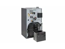
OIL-FIRED NATURAL DRAFT STEAM BOILER — SERIES 4 — Boiler Manual
SERVICETECHNICIANONLY—readandfollowcompletely.
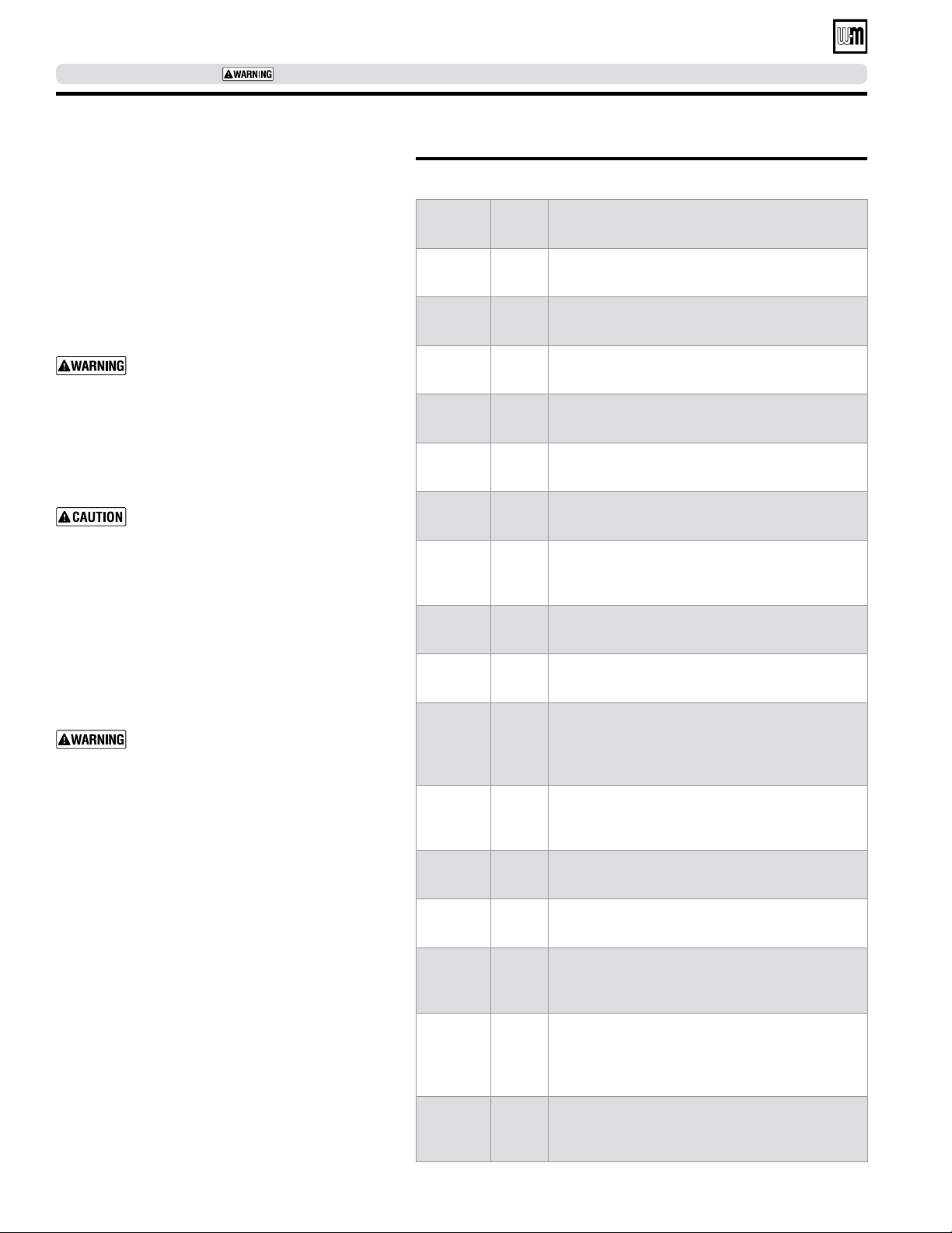
LocationSizeFunction
A1 1½" Skim tapping
A2 2½" Supply piping (sizes 3 - 9)
A3 2½" Supply piping (sizes 6 - 9)
B1 1½" Plugged
B2 2" Return piping
E1 & E2 ½" Float LWCO
E1 ½"
Steam pressure gauge and limit
Control when using probe LWCO
E2 ½" Plugged when using probe LWCO
H ¾" Drain valve
L ¾"
Steam pressure gauge and limit
Control when using float LWCO
Plugged when using probe LWCO)
P ¾" Probe LWCO (plugged when using float LWCO)
R ¾" Relief valve
S1 & S2 ½" Gauge glass
U1 1"
Indirect-fired water heater/ hot water
baseboard supply
U2 ¾"
Operating control for tankless heater (sizes
6-9) or operating control for indirect-fired water
heater (sizes 3-9)
U3 ¾"
Operating control for tankless heater (located
in heater plate — sizes 3-5)
Perform hydrostatic pressure test
1. Refer to Figure 7 and Control Tapping Table 3, to
install:
a. Boiler drain.
b. Water pressure gauge (test only). Be sure gauge
can handle test pressure.
c. Air vent in tapping on top of boiler.
d. Plugs in remaining tappings.
2. Fill boiler. Vent all air. Pressure test boiler at 45-55
psig.
Do not leave boiler unattended. Cold
water fill could expand and damage cast
iron, resulting in severe personal injury,
death or substantial property damage.
3. Check for maintained gauge pressure for more
than 10 minutes. Visually check for leaks if gauge
pressure drops.
4. Drain boiler. Repair leaks if found.
Do not use petroleum-based compounds
to repair leaks. Damage to system com-
ponents can result, causing property
damage.
5. Re-test boiler after repairing leaks.
6. Remove pressure gauge, air vent and plugs from
tappings used for controls.
7. Visually check:
a. Sealing rope placement
b. Metal-to-metal contact around port openings.
c. Flue collector hood seal.
d. Burner mounting door seal.
Obtain gas-tight seal to prevent possible
flue gas leakage and carbon monoxide
emissions, which can lead to severe per-
sonal injury or death.
Table 3 Control tappings (see Figure 7, page 17 for locations)
Install jacket
(Knocked-down boilers only)
Before installing jacket, remove burner mounting door.
See jacket instructions for details.
Install boiler controls
See control tapping location, Figure 7, control tappings,
Table 3, and Figure 8 or Figure 9 on page 17 to install
controls.
1. Do not use Teflon tape to install probe-type low
water cutoff; it will cause low water cutoff to work
improperly.
2. Install tankless heater control if tankless heater is
used. If not furnished, use operating control with
maximum 10°F differential.
3. Make sure gauge glass is last control installed to
prevent breakage.
4. Affix Consumer Protection (CP) number label(s)
on jacket front panel.
Install boiler –
Semi-packaged and Knocked-down boilers only (continued)
Loading ...
Loading ...
Loading ...