

Copyright © 2016 by Julius Tielbürger GmbH & Co. KG, Stemwede Any reproduction, whether in whole or in part, is not permitted. KR-362-169GI REV. 00
Greenkeeper 110
Julius Tielbürger GmbH & Co. KG Maschinenfabrik
Postdamm 12 D-32351 Stemwede-Oppenwehe Germany Tel.: +49 (0) 57 73/80 20 Fax: +49 (0) 57 73/81 75
Website: www.tielbuerger.de
AI-200-001GI
EN – Translation
171506096/0EN

is document is a publication by Julius Tielbürger GmbH & Co. KG, Postdamm 12, D-32351 Stemwede-Oppenwehe, Germany
(www.tielbuerger.de).
e document is up to date with the latest technology at the time of printing. Subject to technical and equipment changes. e
drawings and illustrations shown may dier from the original.
All rights reserved, including those of translation. Any type of reproduction, such as photocopy, microlm or storing in
electronic data processing systems, requires written authorisation from the publisher. Any reproduction, whether in whole or in
part, is prohibited.
All trademarks, registered trademarks, trade names and brand names are the property of their rightful owners and are
acknowledged by us.
© Copyright 2016 by Julius Tielbürger GmbH & Co. KG

3
Content
1 Operating and installation instructions ....................................................................................................................... 4
1.1 General ..................................................................................................................................................................... 4
1.2 Warnings and symbols .............................................................................................................................................. 5
2 Basic safety instructions ................................................................................................................................................ 6
2.1 Intended use .............................................................................................................................................................. 6
2.2 Organisational measures ........................................................................................................................................... 6
2.3 Personnel selection and qualications; basic obligations ......................................................................................... 7
3 Scope and condition of delivery .................................................................................................................................... 8
4 Illustration of the machine and danger zone, component description, position of safety stickers and labels ....... 9
5 Components of the Tielbürger quick-change system ................................................................................................ 10
5.1 Accessories ............................................................................................................................................................. 10
6 Installation .....................................................................................................................................................................11
7 Start-up ......................................................................................................................................................................... 14
7.1 Basic safety instructions for normal operation ....................................................................................................... 14
7.2 Special safety instructions for normal operation .................................................................................................... 14
8 Instruction manual....................................................................................................................................................... 15
9 Exploded drawing ........................................................................................................................................................ 17
10 Manufacturer's declaration ...................................................................................................................................... 18

1.1 General
Operating and installation instructions
1 Operating and installation instructions
4
These operating and installation instructions are in-
tended to help users familiarise themselves with the
product and use it in line with its intended applications.
The operating instructions contain important informa-
tion on how to operate the product safely, properly and
economically. Observing these operating and installa-
tion instructions helps to avert risks, to reduce repair
costs and downtime and to increase the reliability and
service life of the product.
The operating instructions must be supplemented by
the relevant national rules and regulations for accident
prevention and environmental protection.
The operating instructions must always be available
wherever the product is in use.
The operating instructions must be read and applied
by any person in charge of carrying out work with or
on the product, such as:
-Operation, including setting up, fault rectication in
the course of work, removal of production waste,
maintenance and disposal of operating and auxiliary
materials
-Maintenance (servicing, inspection, repair) and/or
-Transport.
The generally recognised rules of technology for safe
and proper working must be observed in addition to
the operating instructions and mandatory regulations
for accident prevention which apply to the country
and place of use.
5
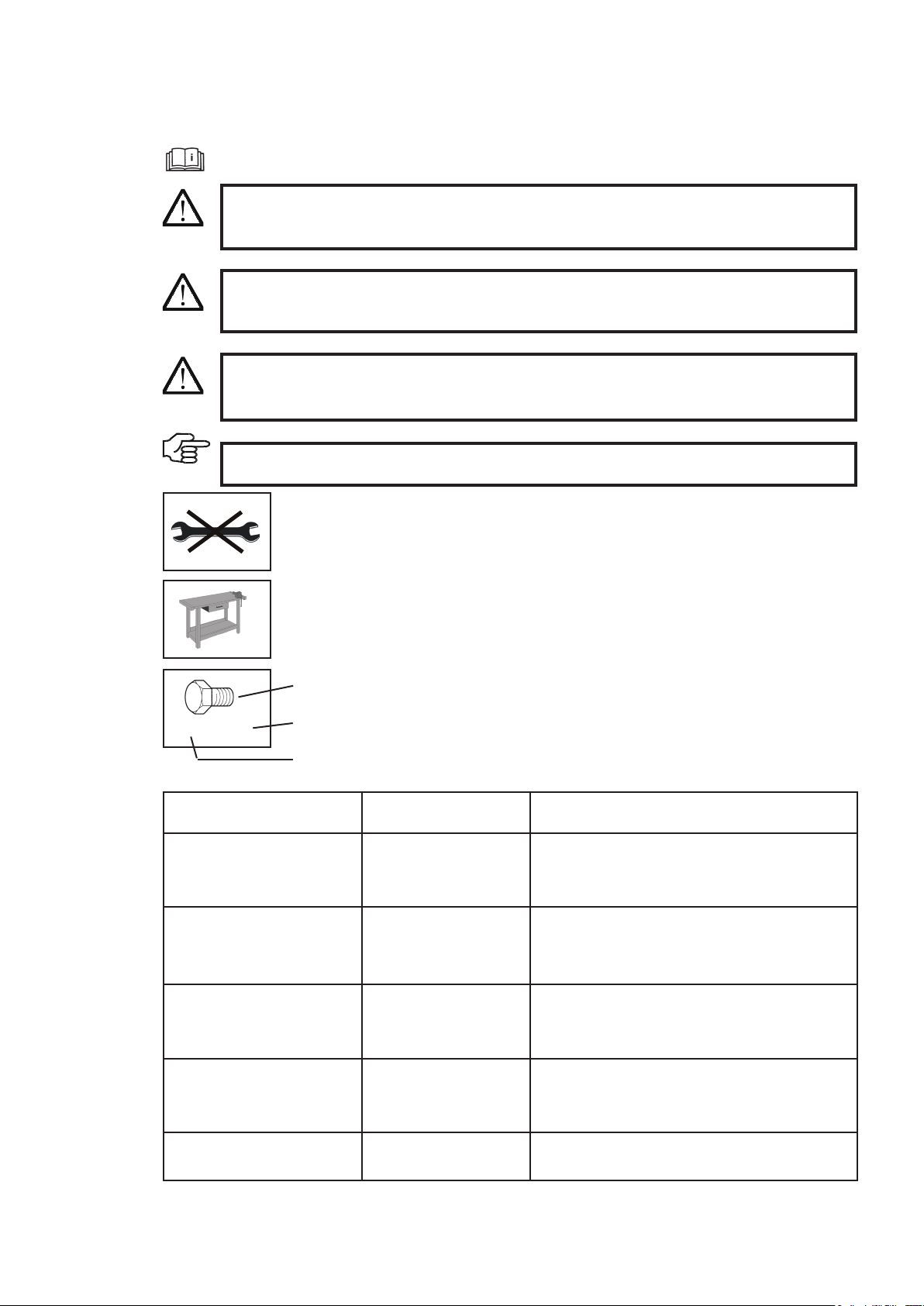
Symbol
Type
Quantity
2x M8 x 20
Read the operating instructions
WARNING:
Indicates a potentially hazardous situation. If this instruction is ignored, there may be a risk
of death or extremely serious injury.
CAUTION:
Indicates a potentially hazardous situation. If this instruction is ignored, there may be a risk
of minor injury.
IMPORTANT:
Indicates operating tips and other useful information.
DANGER!
Indicates an immediate threat of danger. If this instruction is ignored, there is a risk of death
or extremely serious injury.
Operating and installation instructions
1.2 Warnings and symbols
Work on a workbench
Do not use a tool
Symbol
Type
Examples
Explanation
Bolt M8 x 16 M = Metric
S = Diameter in mm
16 = Length in mm
Washer 8.1 - 58 - 5 8.1 = Inner diameter
58 = Outer diameter
5 = Material thickness in mm
Nut M8 (L) M = Metric
8 = Inner diameter in mm
(L) = Lock nut
Combination spanner
Hexagon head screwdriver
Screwdriver
8 8 = Size in mm
Crosshead screwdriver PZ 2
PH 2
PZ 2 = Pozidriv size 2
PH 2 = Phillips size 2

Basic safety instructions
6
2.2 Organisational measures
2.1 Intended use
2 Basic safety instructions
The product has been constructed using state-of-the-art
technology and in line with the recognised technical
safety regulations. However, use of this product may
still result in the risk of injury or death to the user or
third parties, or of damage to the product and other
material assets.
Only use the product in technically perfect working
order, for its intended use and with safety and hazards
in mind, in compliance with the installation instruc-
tions. In particular, you must immediately rectify faults
that could impair safety or have such faults rectied
immediately by a third party.
The product is exclusively intended to be installed
on the machines approved by the manufacturer and
is intended for the accessories approved by the man-
ufacturer.
The Greenkeeper is a lawn maintenance machine
designed to rake moss and thatch out of the lawn.
Regular raking minimises the formation of moss. The
Greenkeeper must not be used to aerate soil – if the
spring tines are positioned too low they can break and
may cause further damage.
Please always observe the setting instructions.
Intended use also includes complying with the instal-
lation instructions and adhering to the inspection and
maintenance conditions.
The operating instructions must always be to hand
wherever the product is in use.
In addition to the operating instructions, observe and
follow the generally valid legal regulations and any
other binding regulations for accident prevention and
environmental protection.
Such obligations may also include handling hazard-
ous substances or making available/wearing personal
protective equipment and complying with road trafc
regulations, for example.
Supplement the operating instructions with instructions
including site management and reporting obligations
concerning special operational requirements, for ex-
ample with regard to work organisation, workows,
personnel used, etc.
Any personnel instructed to perform work on the
product must have read the operating instructions
before starting work, specically the section entitled
"Safety instructions". Reading the instructions after
work has begun is too late. This applies in particular to
personnel who only work on the product occasionally,
for example for set-up and maintenance.
At least occasionally, check that the personnel are
working with safety and hazards in mind while fol-
lowing the
operating instructions.
Personnel must not have long hair which is not tied
back or wear loose clothing or jewellery including
rings. There is a risk of injury from being caught or
drawn into the machine, for example.
Wear personal protective equipment if necessary or
required by regulations.
Observe all safety and hazard notices on the product.
Ensure that all safety and hazard notices at/on the
machine can be read in full at all times.
In the event of any modication to the product or any
change in the product's performance that may affect
safety, shut down the product immediately and report
the fault to the ofce/person responsible.
Do not modify, convert or attach equipment to the
product without approval from the supplier if this could
impair safety. This also applies to tting and adjusting
safety equipment and valves, as well as for welding
on supporting parts.
Spare parts must full the technical requirements
determined by the manufacturer. This must always be
guaranteed for
genuine spare parts.
Adhere to the prescribed time periods or those indi-
cated in the operating instructions for recurring tests/
inspections.
Workshop equipment which is appropriate for the work
is mandatory for carrying out maintenance measures.
Make personnel aware of the location of re extin-
guishers and how to use them.
Observe the re alarm and re ghting procedures.

7
Basic safety instructions
2.3 Personnel selection and qualications; basic obligations
Work on/with the product may only be carried out by
reliable personnel. Observe the legal minimum age.
Only use trained or instructed personnel and clearly
dene the responsibilities of the personnel for opera-
tion, set-up, maintenance and repair.
Ensure that only authorised personnel work on the
product.
Only allow personnel who are yet to complete training,
instruction and induction or who are still completing a
general apprenticeship to carry out work on the prod-
uct under the constant supervision of an experienced
person.
Work on the product's electrical equipment may only
be carried out by a qualied electrician or by trained
personnel under the guidance and supervision of a
qualified electrician in accordance with electrical
engineering regulations.
Work on chassis, braking and steering systems must
only be carried out by qualied personnel trained for
such work.
Only personnel who possess specic knowledge of
and experience in hydraulics are allowed to carry out
work on hydraulic equipment.

Scope and condition of delivery
8
The product is delivered in a collapsible box:
1 Greenkeeper
1 Accessories bag containing
small parts
2 Support wheel
1 Parallel lifting
3 Scope and condition of delivery
1) Product packaging
2) Inspect the original packaging
3) Please recycle the packaging material .
9
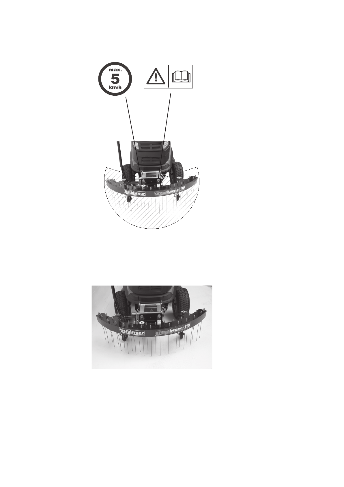
Illustration of the machine and danger zone
4 Illustration of the machine and danger zone, component description, position of safety stickers and labels
Before putting the machine into
operation, read and take note of the
operating and safety instructions.
Diameter = 1.2 m
The Tielbürger quick-change system
10
5.1 Accessories
Ask your authorised Tielbürger specialist dealer for the latest implements.
You can nd further information on our website: www.tielbuerger.de
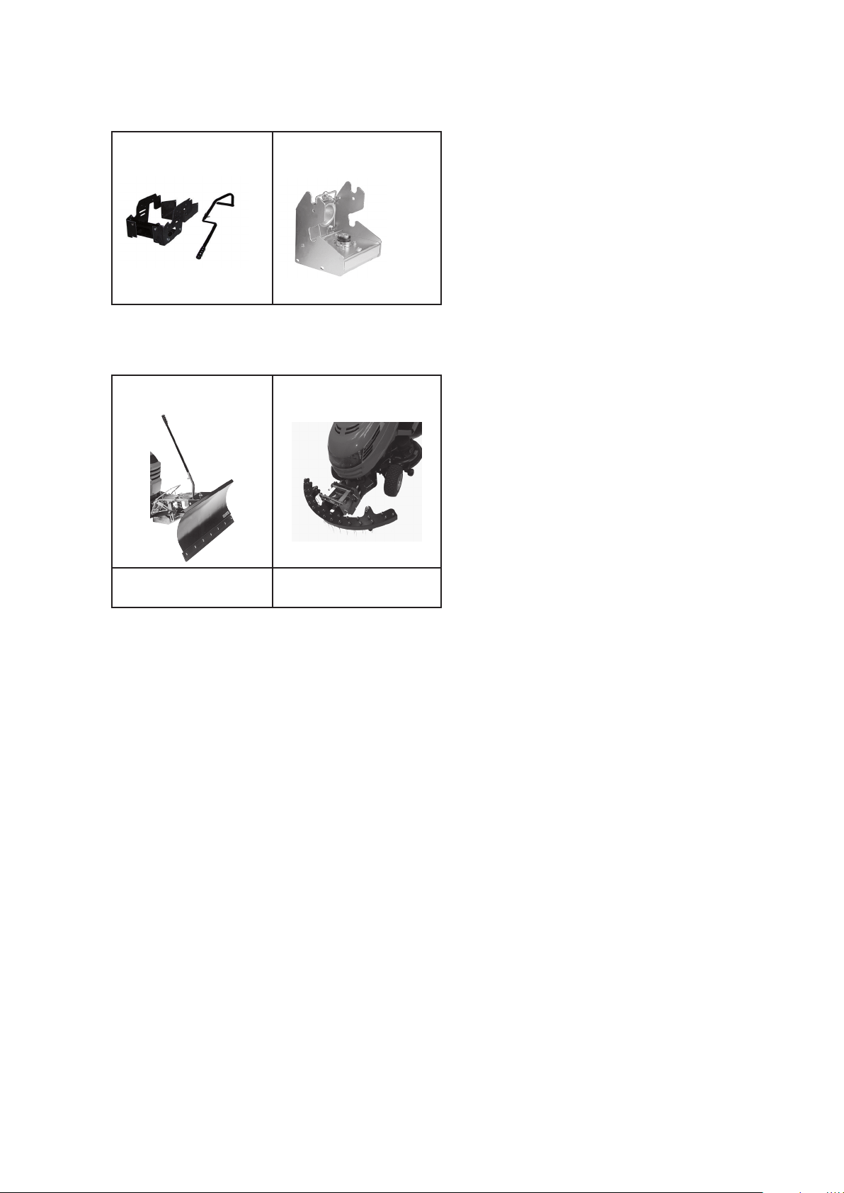
5 Components of the Tielbürger quick-change system
Mounting frame Quick-change mechanism
with drive
1 2
Clearing blade ts125 Greenkeeper 110
min. required
1 + 2
min. required
1 + 2
Installation
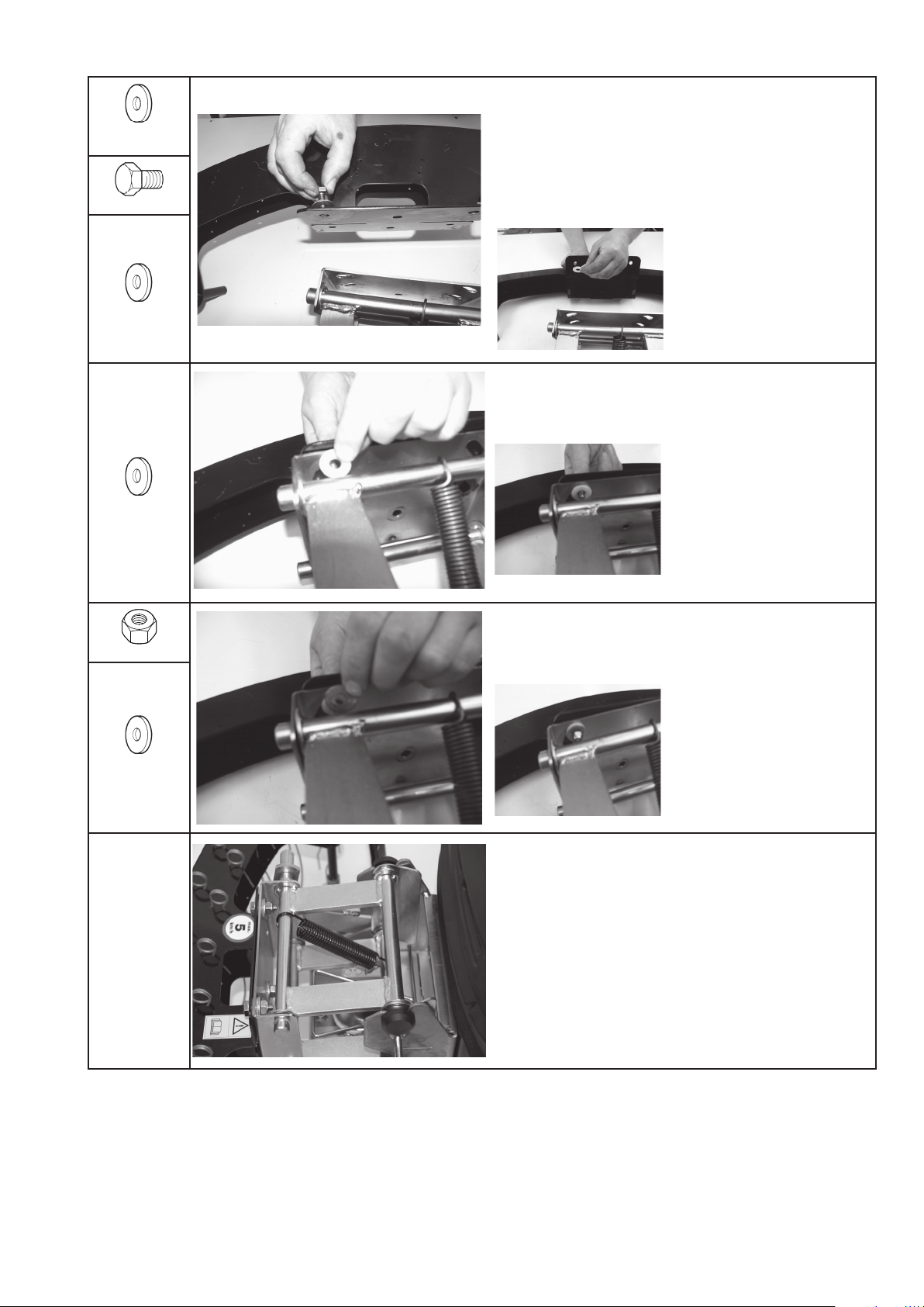
6 Installation
6 x 16.5 x 30 x
42.5
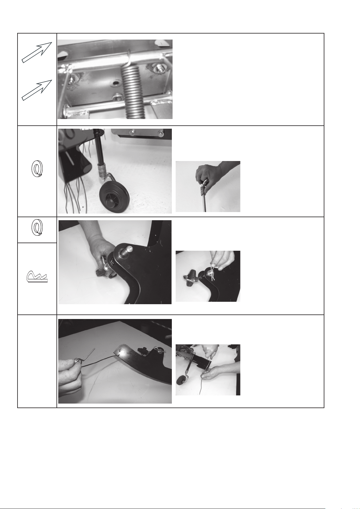
For high quick-change mechanisms above 145 mm (meas-
ured from the lower edge of the quick-change mechanism
to the ground)
Push the bolt with washer through the drilled hole in the
spring holder. Use the upper drilled holes.
3 x M10 x 30
3 x 16.5 x 25 x 2
Place the plastic washer
onto the bolt.
3 x 20.5 x 25 x 2
Guide the spring holder and bolt through the drilled hole in the
parallelogram and push another plastic washer onto the bolt.
3 x M10
Install using a washer and nuts (do not tighten the nuts).
3 x 10.5 x 30
x 2.5
11
12
Installation
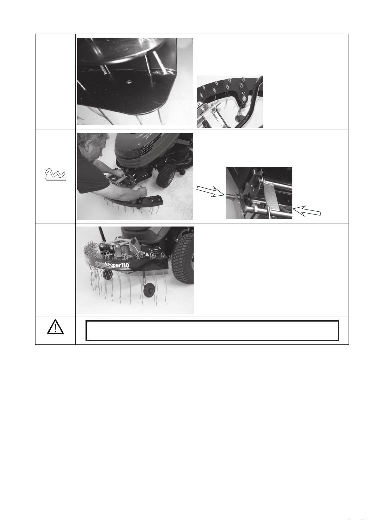
For low quick-change mechanisms below 145 mm
Use the lower drilled holes.
15 x 13 x 28 x 3
Slide the washers onto the swing arm.
(The washers regulate the height. As a default setting, slide
15 washers to the end of the swing arm).
5 x 13 x 28 x 3
Guide the swing arm through the pipe on the spring holder.
1 x 3
Secure using washers and
R-pin.
Insert the spring tine through the front drilled holes.
Press the rear part of the
spring tine together and guide
it through the second drilled
hole.
13
Installation
The rear drilled hole of the in the bottom part of the spring
holder remains unused.
1 x 3
Hook the Greenkeeper 110 into the quick-change mechanism
and secure with bolt and R-pin.
Correctly installed Greenkeeper 110
CAUTION:
Check that all of the screws and nuts are seated rmly.

Start-up
14
7.1 Basic safety instructions for normal operation
7 Start-up
7.2 Special safety instructions for normal operation
Never operate the machine in a manner that could
compromise safety.
Before beginning work, familiarise yourself with the
work environment at the location where the machine
is used. The work environment includes, for example,
obstacles in the work and trafc area, the load-bearing
capacity of the oor and the required means of cordon-
ing the location where the machine is used off from
the public trafc area.
Take appropriate measures to ensure that the product is
only operated in a safe and fully functional condition.
Only operate the product when all protective equipment
and safety-critical equipment, for example detachable
protective equipment, sound-insulating equipment
and extraction equipment, is present and in proper
working order.
Always check for externally visible damage and de-
fects before using the product. Report any machine
modications (including changes in performance) im-
mediately to the ofce/person responsible. Shut down
the product immediately and secure it if necessary.
In the event of a malfunction, shut down and secure
the product immediately. Have faults rectied imme-
diately.
Only start the machine from the driver's seat.
Switch the machine on and off in accordance with the
operating instructions, observing the control displays.
Before switching on/starting up the machine, ensure
that no one can be endangered by the machine starting
up.
Before travelling with the machine or beginning work,
check that the brakes, steering, signal and lighting
systems are fully functional.
Before moving the machine, always check that the
accessories are securely in place.
When driving on public roads and paths and in public
places, comply with the applicable road trafc regu-
lations and bring the machine into a condition which
is permitted by road trafc regulations in advance.
In poor visibility or in the dark, always ensure suf-
cient lighting.
Always maintain an adequate distance from pit edges
and slopes.
Prohibit any manner of working that may impair the
stability of the machine.
Do not drive across slopes; always transport work
equipment and loaded goods close to the ground,
particularly when descending hills.
Always adapt your driving speed to the conditions
on sloping terrain. Never change to a lower gear on a
slope; you should do this before you reach the slope.
Upon leaving the machine, always secure it against
accidentally rolling away and unauthorised use.
Driving behaviour, steering and braking capability and
tipping behaviour are inuenced by the attachments
and ballast weights, so make sure there is sufcient
steering and braking capability.
Do not load the transported goods so high that the
transport trough tips.
Only couple or uncouple the product when it is un-
loaded.
Take special care when coupling and uncoupling the
product – risk of injury!
Observe the permissible axle loads, towing capacities,
total weights and transport dimensions.
In the event of a malfunction, stop the machine and
have faults rectied immediately.
Carrying passengers is not permitted.
15
Instruction manual
8 Instruction manual
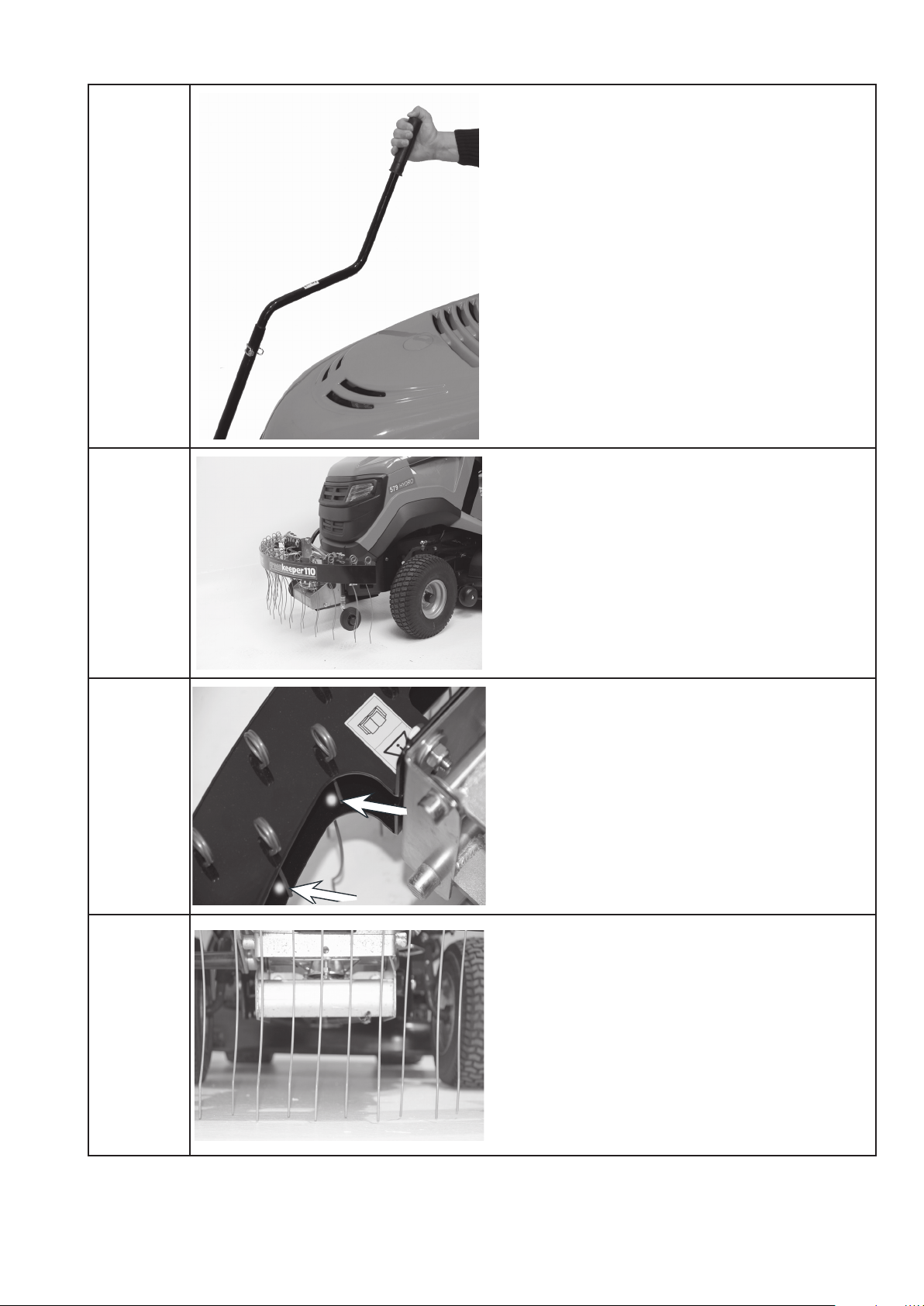
Raise and lower the tool using the control lever.
Keep the tool raised during road transport.
Inserting the spring tines
The short ends of the spring tines point towards the lawn
tractor, the rear lower drilled hole remains unused.
Park the Greenkeeper on a at, solid surface. Use this location
to determine the optimum setting for the spring tines.
Adjusting the spring tines when parked on a solid surface
ensures that they are optimally set up for soft ground (lawns).
16
Instruction manual
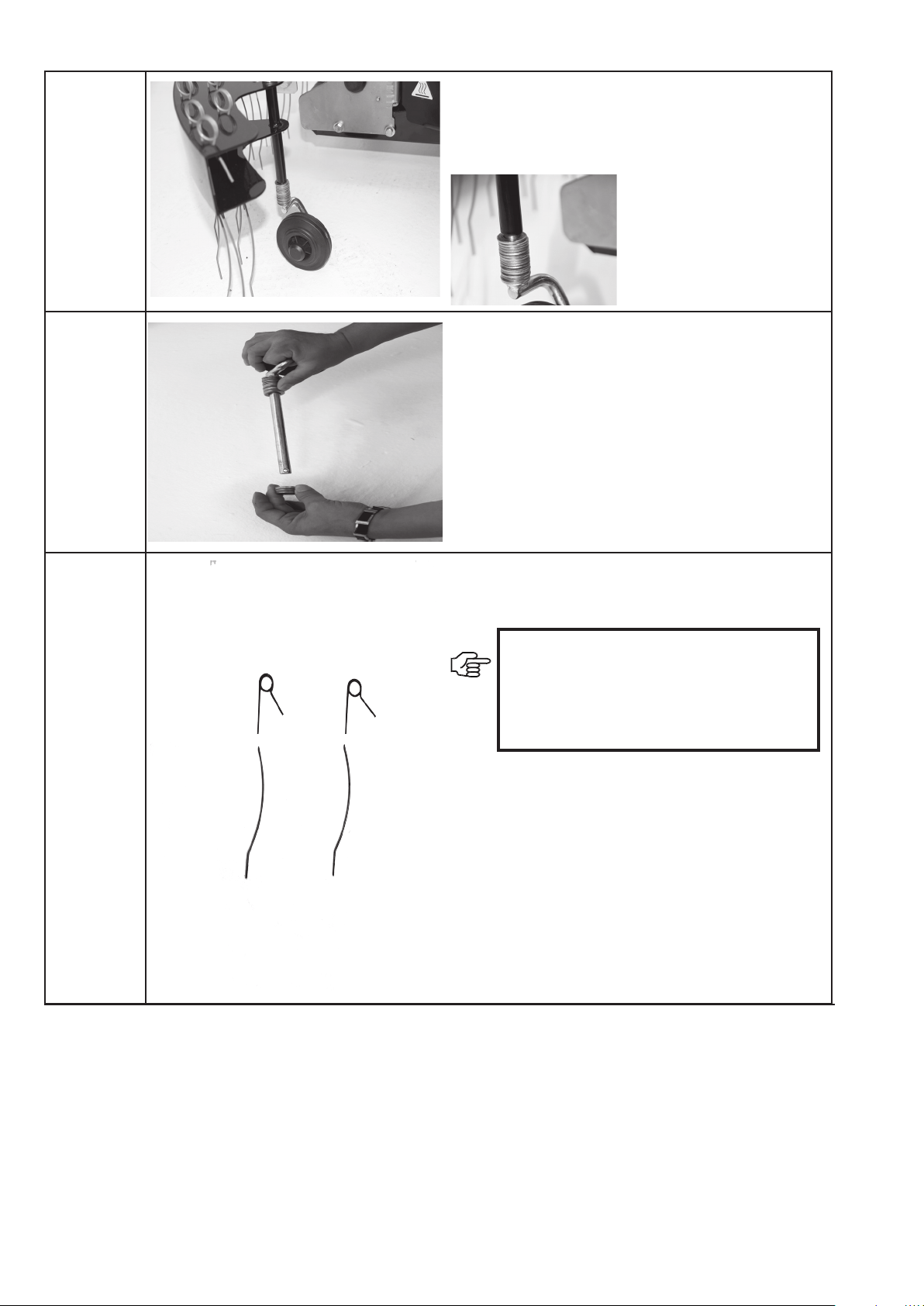
Use the washers to adjust the working height.
The spring tines must not penetrate the soil by more than 2 mm.
The smaller the number of washers used in the lower section,
the further the spring tines penetrate the soil.
1 washer corresponds to an adjustment of 2 mm.
Damage caused by spring tines being set too low.
IMPORTANT:
The Greenkeeper is not suitable for use as
an aerator.
If the spring tines are positioned too low they
can break and may cause damage.
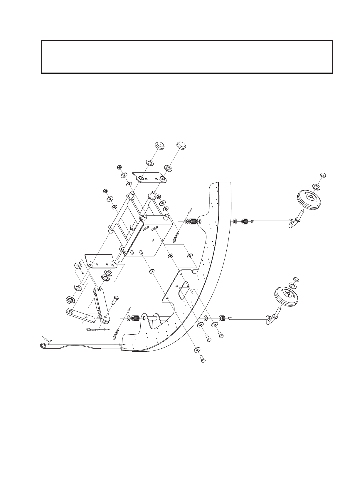
9 Exploded drawing
IMPORTANT:
The "Remarks" column helps you to identify parts. Only use genuine spare parts from the manufacturer.
This ensures that the implement will work reliably.
Item numbers in brackets are wear parts.
Exploded drawing: Installation
17

10 Manufacturer's declaration
Manufacturer: Julius Tielbürger GmbH & Co. KG
Maschinenfabrik
Postdamm 12
D-32351 Stemwede-Oppenwehe, Germany
Note:
The machine described in these operating instructions, together with the Tielbürger
system, is classied as replaceable equipment in accordance with EC Machinery
Directive 2006/42/EC.
The machine may only be used in accordance with these operating instructions.
Any use of the machine not specied in these operating instructions is not permitted.
The declaration of conformity is documented in the operating instructions for the
associated Tielbürger system.
KR-362-169GI
18