Loading ...
Loading ...
Loading ...
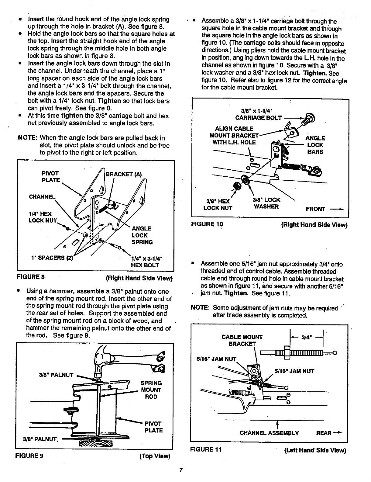
• Insert the round hook end of the angle lock spring
up through the hole in bracket (A). See figure 8.
• Hold the angle lock bare so that the square holes at
the top. Insert the straight hook end of the angle
lock spring through the middle hole in both angle
lock bars as shown in figure 8.
• Insert the angle lock bars down through the slot in
the channel. Underneath the channel, place a t"
long spacer on each side of the angle lock bars
and insert a 1/4" x 3-1/4' bolt through the channel,
the angle lock bars and the spacers. Secure the
bolt with a 1/4' lock nut. Tighten so that lock bars
can pivot freely. See figure 8.
• At this time tighten the 3/8 = carriage bolt and hex
nut previously assembled to angle lock bars.
NOTE: When the angle lock bars are pulled back in
slot, the pivot plate should unlock and be free
to pivot to the right or left position.
PIVOT BRACKET (A)
PLATE
CHANNEL
1/4' HEX
LOCKI_
LOCK
SPRING
1" SPACERS
!/4' x 3-1/4"
HEX BOLT
FIGURE 8
(Right Hand Side Vle_
Using a hammer, assemble a 3/8" palnut onto one
end of the spring mount rod. Insert the other end of
the spring mount rod through the pivot plate using
the rear set of holes. Support the assembled end
of the spring mount rod on a block of wood, and
hammer the remaining palnut onto the other end of
the rod. See figure 9.
3_'PALNUT
SPRING
MOUNT
ROD
3/8" PALNUT,
PIVOT
PLATE
FIGURE 9
(Top View)
Assemble a3/8" x 1-1/4" carriage bolt through the
square hole in the cable mount bracket and through
the square hole in the angle lock bars as shown In
figure 10. (The carriage bolts should face in opposite
directions.) Using pliers hold the cable mount bracket
in position, angling down towards the L.H. hole in the
channel as shown in figure 10. Secure with a 3/8"
lock washer and a 3/8" hex lock nut. Tighten. See
figure 10. Refer also to figure 12 for the correct angle
for the cable mount bracket.
3/8" x 1-1/4"
CARRIAGE BOLT
ALIGN CABLE
MOUNTBRACKET ANGLE
WITH LH. HOLE LOCK
BARS
3/8"HEX 3/8"LOCK
LOCK NUT WASHER FRONT
FIGURE 10
(Right Hand Side View)
Assemble one 5/16' jam nut approximately 3/4' onto
threaded end of control cable. Assemble threaded
cable end through round hole in cable mount bracket
as shown in figure 11, _md secure with another 5/16"
jam nut. Tighten. See figure 11.
NOTE: Some adjustment ofjam nuts may be required
after blade assembly is completed.
CABLE MOUNT 3/4"
BRACKET
5/16" JAM NUT '_
5/16" JAM NUT
t
CHANNEL ASSEMBLY REAR
FIGURE 11
(Left Hand Side View)
7
Loading ...
Loading ...
Loading ...