Loading ...
Loading ...
Loading ...
TOOLS REQUIRED FOR ASSEMBLY
(I)
(i)
(i)
Pliers
Hemmer
Adjustable Wrench (or socket set)
9/16" Open End or Box End Wrench
7/16" Open End or Box End Wrench
1/2" Open End or Box End Wrench
• REMOVAL OF PARTS FROM CARTON
• Remove the loose parts and the hardware packages
from the carton. Lay out all parts and hardware and
identify using the illustrations on pages 3 and 4.
NOTE: Right hand (R.H.) and left hand (LH.) are deter-
mined from the operators position while seated
on the tractor.
&
CAUTION: Do not begin assembling
until the tractor engine, muffler and
exhaust deflector have been allowed
to cool off.
TRACTOR PREPARATION
• Allow engine, muffler and exhaust deflector to cool
before beginning.
• Refer to tractor owners manual to remove mower
deck or any other attachment you may have mounted
to your tractor. Mark all loose parts and save for
re-assembly.
• Refer to tractor owner's manual to remove tractor
hood for easier assembly of blade to tractor frame.
IF YOUR TRACTOR HAS FRONT SUSPENSION
BRACKETS LIKE FIGURE 1
• Remove two bolts from each side of the tractor
frame as shown in figure 1.
NOTE: Bolts should be assembled back into the holes
if the hanger brackets (figure 2) are removed from
the tractor frame.
REMOVE BOLTS FROMTHESE HOLES
FIGURE 1
FRONT
SUSPENSION
BRACKET
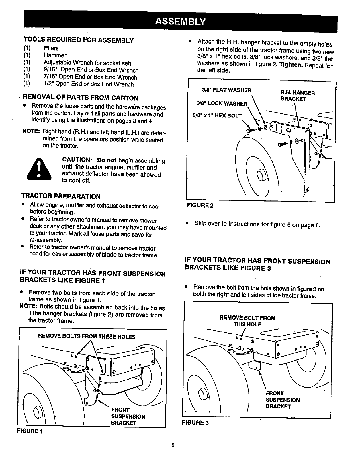
,, Attach the R.H. hanger bracket to the empty holes
on the right side of the tractor frame using two new
3/8' x 1" hex bolts, 3/8" lock washers, and 3/8" flat
washers as shown in figure 2. Tighten. Repeat for
the left side.
3/8" FLAT WASHER R,H. HANGER
3/8" LoCK WASHER \ ' BRACKET
!
FIGURE2
• Skip over to instructions for figure 5 on page 6.
IF YOUR TRACTOR HAS FRONT SUSPENSION
BRACKETS LIKE FIGURE 3
• Remove the bolt from the hole shown in figure 3 on
bolth the right and left sides ofthe tractor frame.
FIGURES
THIS HOLE
Loading ...
Loading ...
Loading ...