W10858718B
W10858720B - SP
If you have any problems or questions, visit us at www.whirlpool.com
Pour tout problème ou toute question, consulter www.whirlpool.ca
Use & Care Guide
Guide d’utilisation et d’entretien
Heat Pump Dryer
Sécheuse avec pompe à chaleur
Para obtener acceso
al Manual de uso y
cuidado en español, o para
obtener información adicional
acerca de su producto, visite:
www.whirlpool.com.
2
DRYER SAFETY
Table of Contents
DRYER SAFETY ......................................................................2
OPERATING INSTRUCTIONS ............................................... 4
ACCESSORIES ................................................................. 4
HEAT PUMP TECHNOLOGY ............................................5
CONTROL PANEL AND FEATURES .................................6
PROGRAM/CYCLE GUIDE ............................................... 7
USING YOUR DRYER .......................................................9
DRYER CARE .................................................................12
INSTALLATION INSTRUCTIONS ......................................... 14
INSTALLATION REQUIREMENTS ...................................14
LOCATION REQUIREMENTS .........................................15
DRAIN SYSTEM ..............................................................16
ELECTRICAL REQUIREMENTS – U.S.A. ONLY .............17
ELECTRIC DRYER POWER HOOKUP –
CANADA ONLY ............................................................... 18
ELECTRIC INSTALLATION – U.S.A. ONLY ....................18
LEVEL DRYER ................................................................24
COMPLETE INSTALLATION CHECKLIST .......................24
DOOR REVERSAL (OPTIONAL) ......................................25
TROUBLESHOOTING ...........................................................30
WARRANTY ........................................................................... 35
ASSISTANCE OR SERVICE .................................. Back Cover
Table de matières
SÉCURITÉ DE LA SÉCHEUSE .............................................36
INSTRUCTIONS D’UTILISATION ........................................ 37
ACCESSOIRES ............................................................... 37
TECHNOLOGIE DE POMPE À CHALEUR ......................38
TABLEAU DE COMMANDE ET CARACTÉRISTIQUES ... 39
GUIDE DE PROGRAMMES ............................................40
UTILISATION DE LA SÉCHEUSE ....................................42
ENTRETIEN DE LA SÉCHEUSE......................................45
INSTRUCTIONS D’INSTALLATION ..................................... 47
EXIGENCES D’INSTALLATION .......................................47
EXIGENCES D’EMPLACEMENT .....................................48
SYSTÈME DE VIDANGE .................................................49
SPÉCIFICATIONS ÉLECTRIQUES –
ÉTATS-UNIS SEULEMENT .............................................50
RACCORDEMENT DE LA SÉCHEUSE ÉLECTRIQUE –
CANADA UNIQUEMENT .................................................51
INSTALLATION ÉLECTRIQUE –
ÉTATS-UNIS SEULEMENT ............................................51
RÉGLAGE DE L’APLOMB DE LA SÉCHEUSE ................57
LISTE DE VÉRIFICATION POUR
INSTALLATION TERMINÉE ............................................. 57
INVERSION DE LA PORTE (FACULTATIF) ......................58
DÉPANNAGE .........................................................................63
GARANTIE .............................................................................66
ASSISTANCE OU SERVICE ...................... Couverture arrière
3
n Do not repair or replace any part of the dryer or attempt
any servicing unless specically recommended in
this Use and Care Guide or in published user-repair
instructions that you understand and have the skills
to carry out.
n Do not use fabric softeners or products to eliminate static
unless recommended by the manufacturer of the fabric
softener or product.
n Do not use heat to dry articles containing foam rubber or
similarly textured rubber-like materials.
n Clean lint screen before or after each load.
n Keep the grille on the rear of the dryer free from the
accumulation of lint, dust, and dirt.
n The interior of the appliance should be cleaned
periodically by qualied service personnel.
n See “Electrical Requirements” in “Installation
Instructions” for grounding instructions.
IMPORTANT SAFETY INSTRUCTIONS
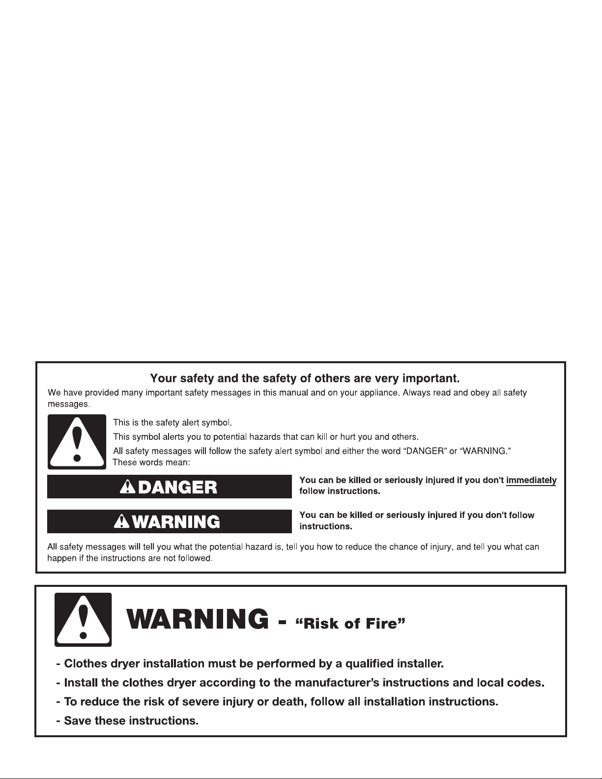
WARNING: To reduce the risk of re, electric shock, or injury to persons when using the dryer, follow basic precautions,
including the following:
SAVE THESE INSTRUCTIONS
n Read all instructions before using the dryer.
n Do not place items exposed to cooking oils in your dryer.
Items contaminated with cooking oils may contribute to a
chemical reaction that could cause a load to catch re. .
n Do not dry articles that have been previously cleaned
in, washed in, soaked in, or spotted with gasoline,
dry-cleaning solvents, or other ammable or explosive
substances as they give off vapors that could ignite or
explode.
n Do not allow children to play on or in the dryer. Close
supervision of children is necessary when the dryer is
used near children.
n Before the dryer is removed from service or discarded,
remove the doors to the drying compartment.
n Do not reach into the dryer if the drum is moving.
n Do not install or store the dryer where it will be exposed
to the weather.
n Do not tamper with controls.
4
Accessories
INSTALLATION & MAINTENANCE
ACCESSORIES
FACTORY CERTIFIED PARTS – these three
words represent quality parts and accessories
designed specically for your appliance.
Time tested engineering that meets
our strict quality specications.
FACTORY CERTIFIED PARTS
Accessories designed for your appliance:
Enhance your new washer and dryer with the following
genuine Whirlpool accessories. For more information
on options and ordering, call 1-866-698-2538, or visit us
at: www.whirlpool.com/accessories. In Canada, call
1-800-688-2002 or visit us at www.whirlpoolparts.ca.
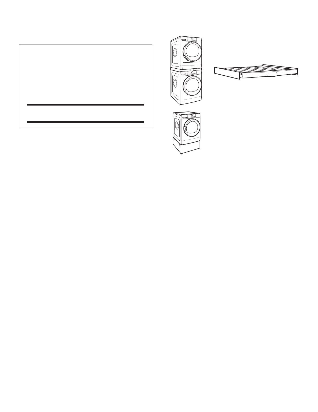
Stack Kit
If space is at a premium, the stack kit
allows the dryer to be installed on top
of the washer.
OPERATING INSTRUCTIONS
12" Pedestal
Color-matched pedestals raise the
washer and dryer to a more comfortable
working height.
5
Use Automatic Cycles for better fabric care and energy savings
Use the Automatic Cycles to provide the most energy savings and enhanced fabric care from the dryer. During Automatic Cycles,
heat pump unit temperature and moisture level are sensed in the load. This sensing occurs throughout the drying cycle and the
dryer shuts off when the load reaches the selected dryness. Use the NORMAL dryness level to provide optimal energy savings.
With Timed Dry, the dryer runs the amount of time set and can result in shrinkage, wrinkling, and static due to over-drying.
Use Timed Dry for the occasional damp load that needs a little more drying time.
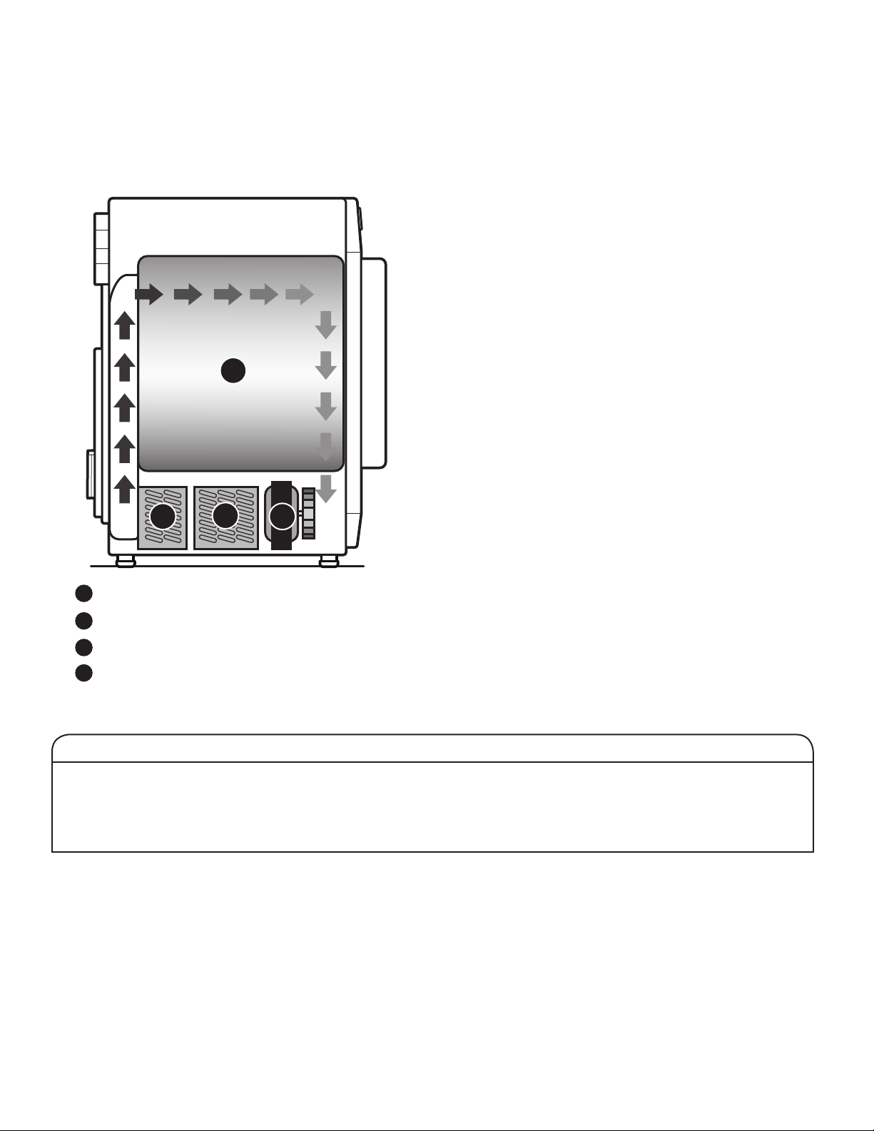
Condenser is heating up the air
Drying
Air blower
Evaporator is drying air and discharging
condensation water
1
2
3
4
3
4
2
1
Heat Pump Technology
A typical dryer uses large amounts of energy; this dryer consumes a fraction of the energy by recycling and reclaiming heat.
This dryer is a ventless heat pump dryer that uses a refrigeration system to dry and recycle the same air. The laundry
is dried with low temperatures; therefore it may feel cooler than expected during and after the drying process.
The heat pump dryer’s heating phase is longer than in traditional dryers. If possible, do not open the dryer door during the process
as heat can escape from the drum and can make longer drying times.
Benets of a Heat Pump
• ENERGY: Regenerates energy to reduce overall energy
consumption.
• PERFORMANCE: Allows flexibility to manage drying
performance and energy savings.
• FABRIC CARE: Capability to use less heat than vented dryer.
• VENTLESS DESIGN: Allows installation in more locations
throughout the home.
New Sounds from a Heat Pump
• Dryer runs on a compressor like your refrigerator and you
may notice a hum from the compressor.
• The water from wet clothes is pumped out to your drain or
water tank. You may notice a gurgling sound occasionally.
Heat Pump Unit
6
Control Panel and Features
Options
Delay
Start
Timed
Dry
Dryness
Level
P
Program
3 Sec
Cycle
Signal
Control
Lock
Hold 3 Sec
Steam
X-Dry
Dry
Damp
Dry
Mixed
Heavy Duty
Normal
Synthetics
Delicates
Wool
Air Dry
Refresh
Timed Dry
Bulky/Bedding
8
3 9
1 2 5
A B C
D A
B
4
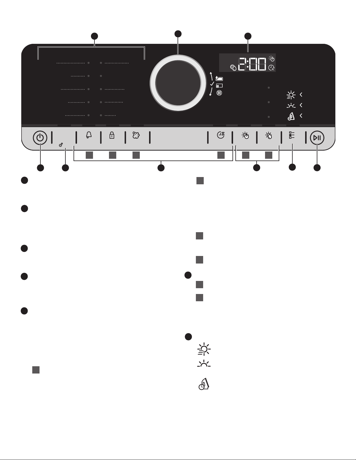
POWER BUTTON
Touch until the indicator above the Program button lights
up. Symbols appear on the control panel and sounds are
played.
PROGRAM (cycle)
When you turn on the dryer, the light above this button
will turn on. The program settings which you used last
will appear on the control panel. This button also lets you
set water conductivity (see “Adapting the dryer to water
conductivity” for more information).
PROGRAM/CYCLE AREA
An indicator next to each program/cycle lights up as you
use the knob to scroll through the list. Press the knob when
the indicator next to the desired program/cycle lights up.
CONTROL KNOB
Turn the knob to select a program/cycle for your laundry
load, change dryness level, set drying time or delay start
time, or select Other Options. Press the knob to confirm
your selection.
OPTIONS
Touch to activate additional dry options or additional
features on the dryer before touching the Start/Pause
button. Additional dry options or additional features
selected after touching the Start/Pause button may
not be activated.
To return to factory default cycle settings, unplug the dryer
for 30 seconds, then plug back in.
NOTE: Not all options are available with all cycles.
Cycle Signal
Use to turn on or off the signal indicating the end
of a drying cycle.
NOTE: Touch and hold the Cycle Signal button for
about one second to turn sounds on or off.
Control Lock
Use to lock the controls of the dryer and avoid
an accidental change in cycle options or preferences
during a drying cycle.
Touch and hold CONTROL LOCK to lock or unlock
the controls of the dryer.
NOTE: The Control Lock function may be enabled
when recovering from a power failure. To unlock
the control, touch and hold CONTROL LOCK.
Steam
Touch to activate the Steam option, which adds
humidity to the end of the Heavy Duty, Normal,
or Synthetics cycle to help smooth out wrinkles.
Delay Start
Touch to start your program/cycle at a later time.
SETTINGS
Timed Dry
Sets the length of a Timed Dry cycle.
Dryness Level
When using some Automatic Cycles, you may
select a Dryness Level based on the type of load
you are drying.
NOTE: Dryness Level is for use with Automatic
Cycles only.
OTHER OPTIONS
Save Time
This option provides quicker drying.
Gentle
This option dries laundry more gently by reducing
the drying temperature.
Wrinkle Shield
™
This option helps to avoid creasing if you cannot
unload the laundry soon after the program/cycle
ends. The dryer starts to tumble the laundry
periodically a few minutes after the program/cycle
ends. This tumbling will last up to approximately
12 hours. Tumbling can be stopped any time by
touching the Power button to turn off the dryer.
7
1
2
3
4
5
7
B
A
C
D
A
B
6
6
7
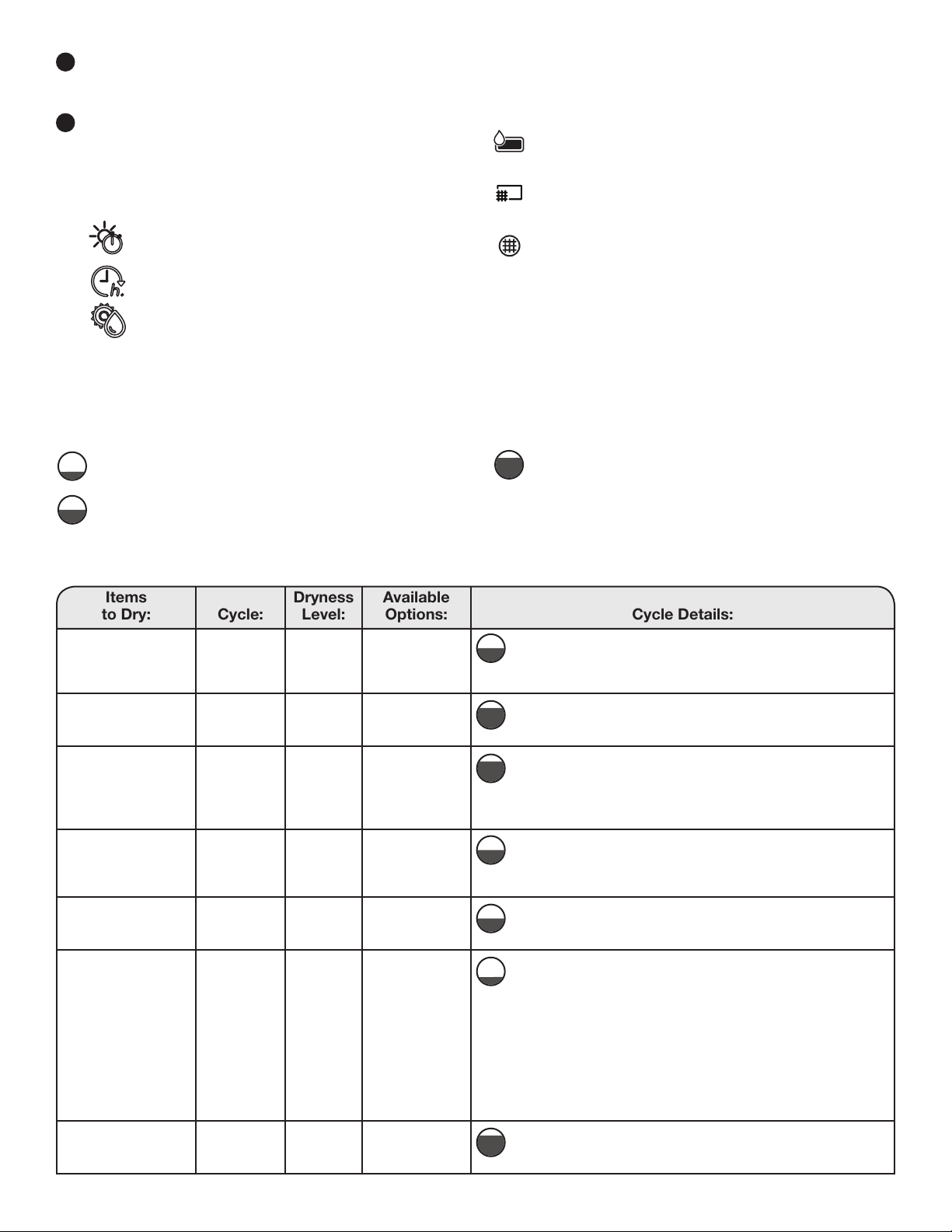
Items
to Dry:
Cycle:
Dryness
Level:
Available
Options:
Cycle Details:
Mixed laundry
made of cotton,
linen, or synthetic
fibers and blends
Mixed
Dry
Wrinkle Shield
™
Uses Medium heat to dry large loads of mixed fabrics and
items.
Heavyweight items
or heavy work
clothes
Heavy Duty
Dry
Steam
Wrinkle Shield
™
Gentle
Offers stepped drying, starting with High heat followed by
Medium heat for enhanced fabric care and energy savings.
Work clothes,
mixed cottons,
corduroys
Normal Extra Dry
Dry
Damp Dry
Steam
Dryness Level
Wrinkle Shield
™
Gentle
Save Time
Uses Medium heat to dry large loads of cotton or mixed
fabrics and items. Tumbling reverses intermittently to
redistribute the load for thorough drying.
Normally soiled
laundry made of
artificial fibers or
cotton blends
Synthetics Extra Dry
Dry
Damp Dry
Steam
Dryness Level
Wrinkle Shield
™
Gentle
Uses lower heat than the Normal cycle. Tumbling reverses
intermittently to redistribute the load for thorough drying.
Undergarments,
blouses, lingerie,
performance wear
Delicates
Dry
Wrinkle Shield
™
Uses Extra Low heat to gently dry delicate items.
Wool items labelled
with the Woolmark
logo and identified
as machine
washable, as well
as textiles made of
silk (see care label
recommendations),
linen, wool, and
viscose marked as
hand-wash only
Wool
Dry
N/A
Uses Low heat to provide a short, finishing touch to items
that have been air-dried.
Comforters, pillows,
sheets
Bulky/
Bedding
Dry
Wrinkle Shield
™
Use for drying large, bulky items; do not overfill dryer drum.
Partway through the cycle, the signal will sound to indicate
when it is time to rearrange items for optimal drying.
Program/Cycle Guide – Automatic Cycles
Settings and options shown in bold are default settings for that cycle. If settings are changed, the new settings will be remembered.
If there is a power failure, settings will return to the default. Not all settings and options are available on each cycle.
Use Automatic Cycles for better fabric care and energy savings
The dryer senses moisture in the load or air temperature and shuts off when the load reaches the selected dryness level.
Use the NORMAL dryness level to provide optimal energy savings.
Load Size Recommendations
For best results, follow the wet load size recommendations noted for each cycle.
Small load: Fill the dryer drum with 3–4 items, not more
than ¼ full.
Medium load: Fill the dryer drum up to about ½ full.
Large load: Fill the dryer drum up to about ¾ full.
Do not pack tightly. Items need to tumble freely.
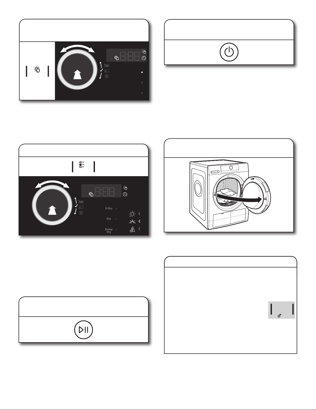
START/PAUSE BUTTON
Touch to start, or touch and hold to pause, a program/
cycle.
LED DISPLAY
When you select a program/cycle, its default settings
will light up and the Estimated Time Remaining will be
displayed. Factors such as load size and dryness level
may affect the time shown in the display.
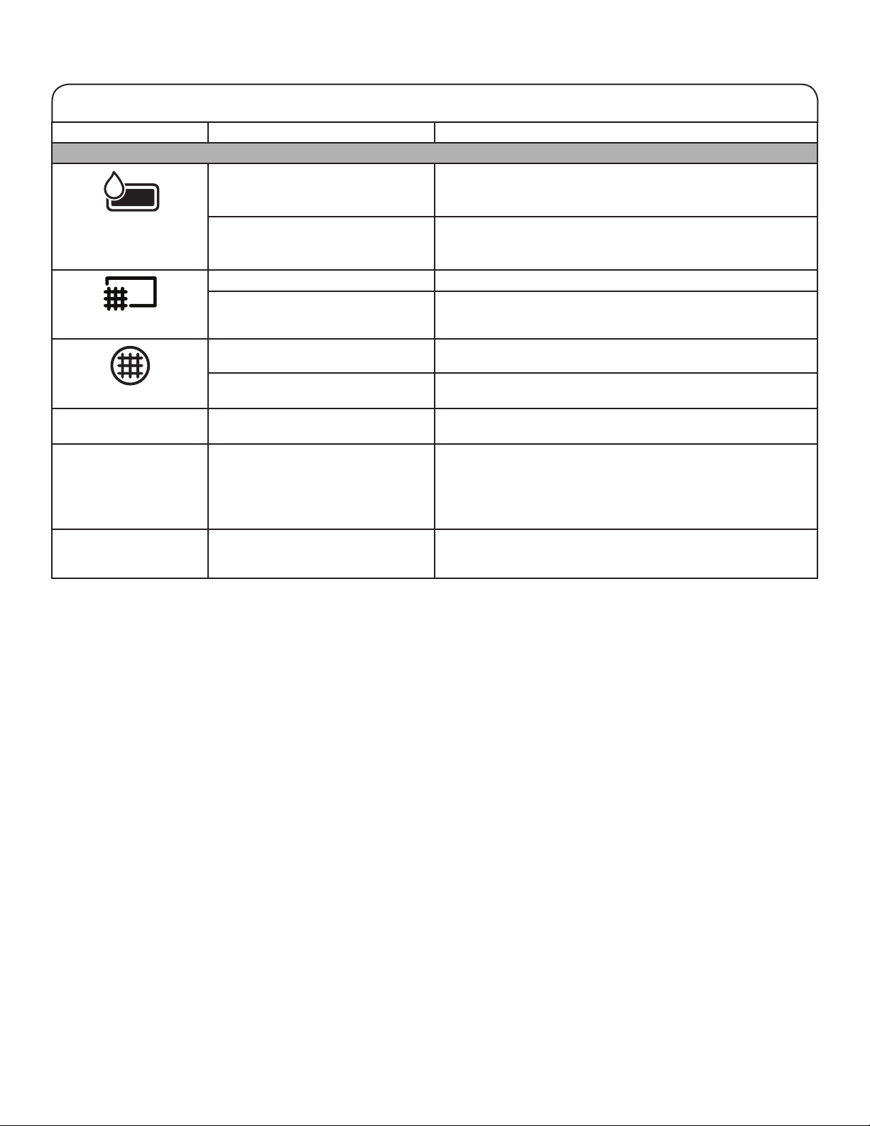
Symbols
Drying time
Delay start
Conductivity adjustment
STATUS INDICATORS (next to control knob)
These indicators will light up to alert you when certain
conditions occur.
Symbols
Water tank full (see “Empty Water Tank” in “Using Your
Dryer”)
Clean bottom filter (see “Cleaning the Bottom Filter” in
“Dryer Care”)
Clean door filter (see “Cleaning the Lint Screen”
in “Dryer Care”)
8
9
8
Load Size Recommendations
For best results, follow the wet load size recommendations noted for each cycle.
Small load: Fill the dryer drum with 3–4 items, not more
than ¼ full.
Medium load: Fill the dryer drum up to about ½ full.
Large load: Fill the dryer drum up to about ¾ full.
Do not pack tightly. Items need to tumble freely.
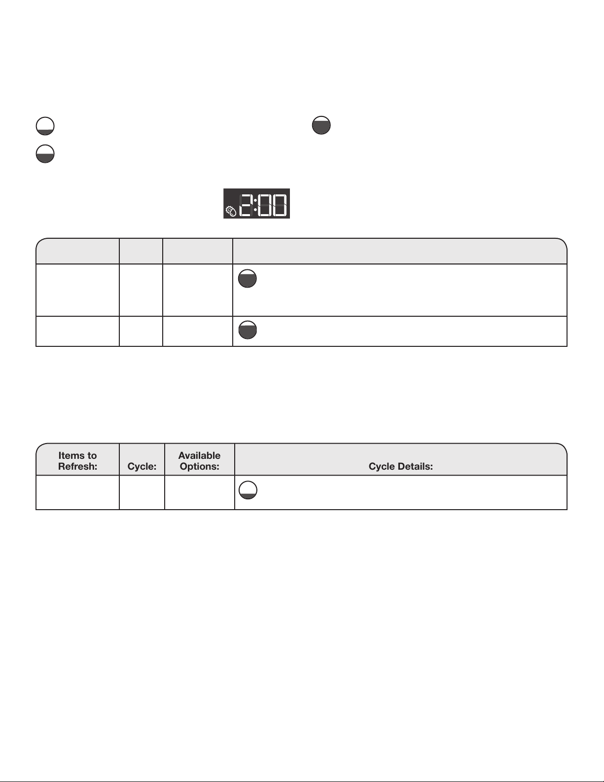
Items
to Dry:
Cycle:
Available
Options:
Cycle Details:
Any load
NOTE: Line dry
foam, rubber,
plastic, or heat-
sensitive fabrics.
Air Dry Wrinkle Shield
™
For airing out, refreshing, and loosening up laundry without heating.
Any load Timed
Dry
Wrinkle Shield
™
Use to dry items with low heat to a damp level for items that do not require
an entire drying cycle.
Adjust drying time on Timed Dry Cycles
When you select the Timed Dry or Air Dry
cycle, the time appears in the display. Use
the knob to set the drying time from 10 to
180 minutes (3 hours).
Program/Cycle Guide – Adjustable Time Cycles
Settings and options shown in bold are default settings for that cycle. If settings are changed, the new settings will be
remembered. If there is a power failure, settings will return to the default. Not all settings and options are available on each cycle.
Program/Cycle Guide – Refresh Cycle
The Refresh cycle is designed for use with dry loads to loosen wrinkles, reduce odors, and refresh fabrics.
Items to
Refresh:
Cycle:
Available
Options:
Cycle Details:
Shirts, blouses,
and slacks
Refresh
Dry
Use to reduce odors and light wrinkles. Do not add dryer sheets. Before
loading laundry into the drum, spray it with a maximum of 6.8 oz (200 ml)
water.
9
Using Your Dryer
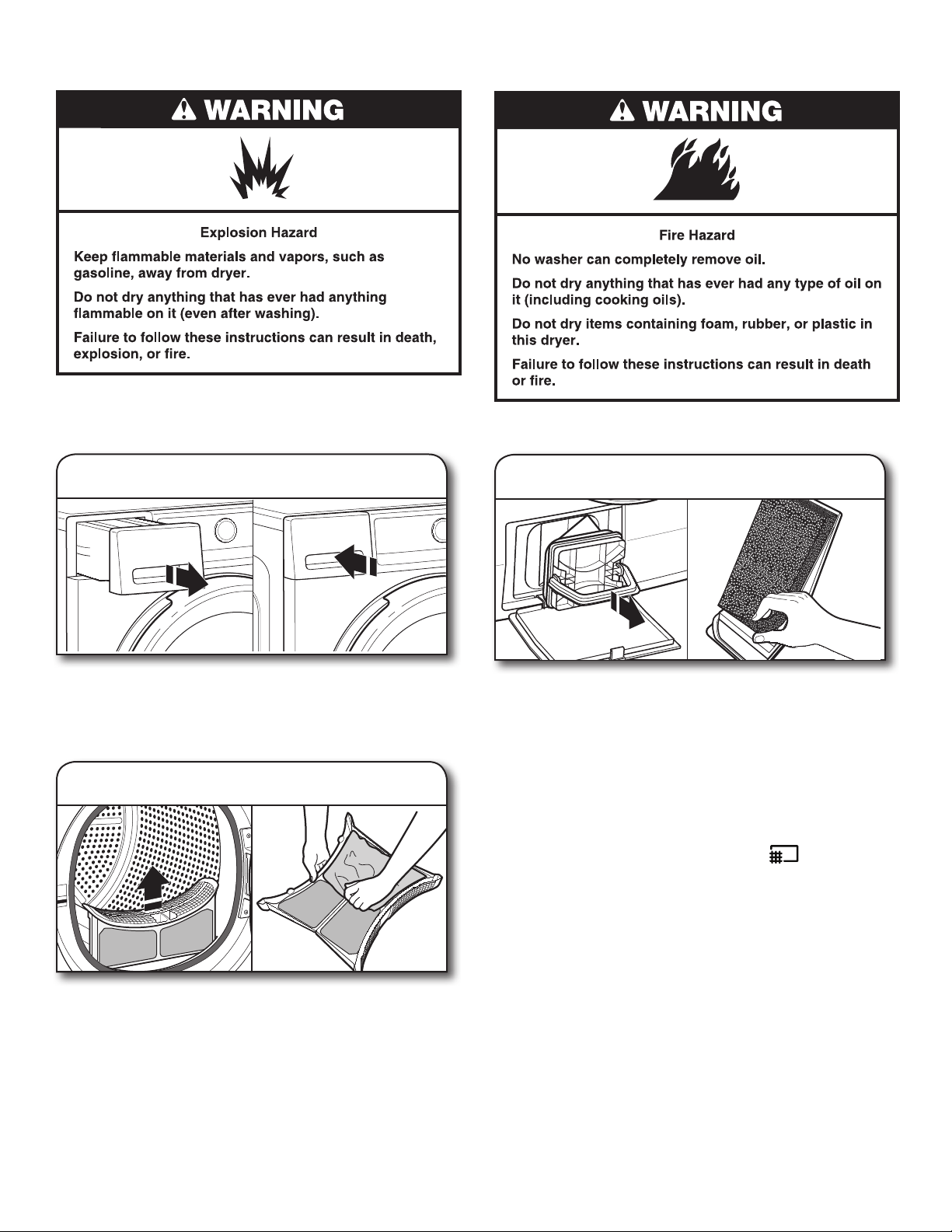
WARNING: To reduce the risk of fire, electric shock, or injury to
persons, read the IMPORTANT SAFETY INSTRUCTIONS before
operating this appliance.
1. Empty water tank
Hold the handle and carefully pull out the water tank.
Holding the full water tank with both hands, empty out the
water. Then push the container back into place. Make sure
that it is properly inserted.
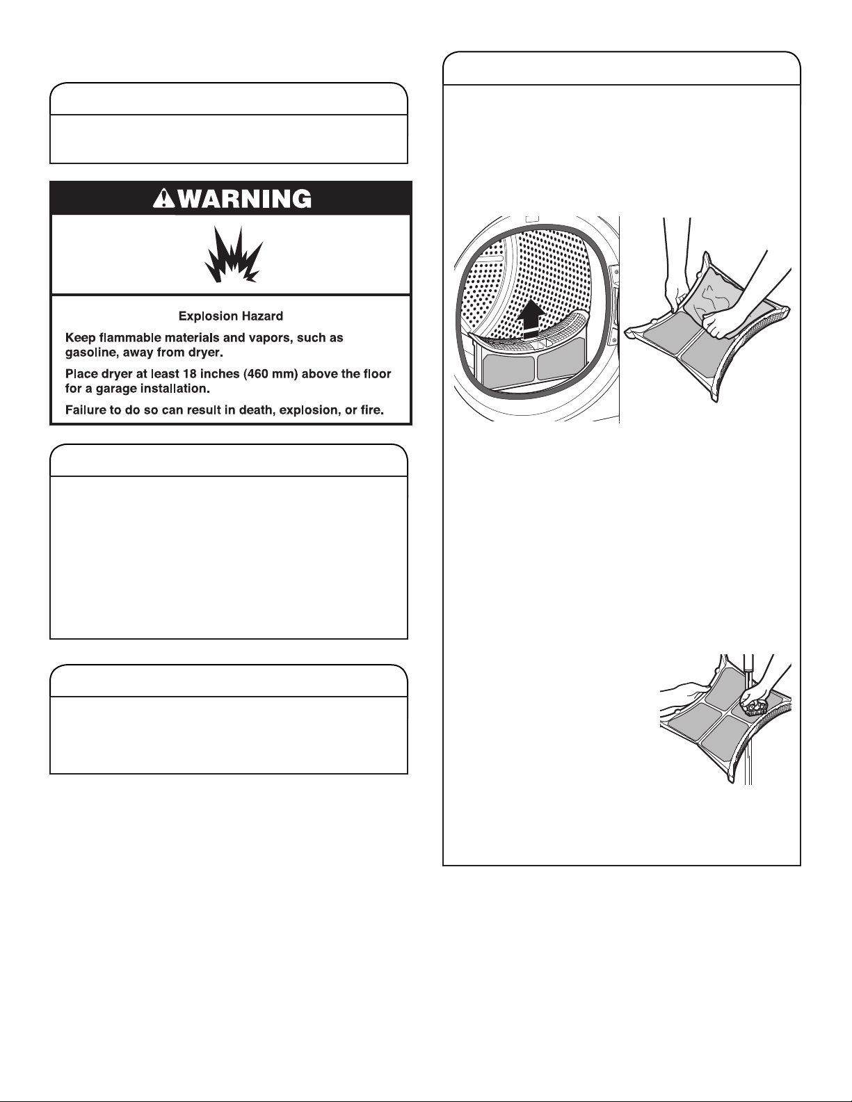
2. Clean door lint screen
Clean the lint screen before each load. Pull the lint screen
straight up and out. Press tab down and open lint screen.
Roll lint off the screen with your fingers. Push the lint screen
firmly back into place.
IMPORTANT: Clean lint screen before each dryer use
as a screen blocked with lint will increase drying time.
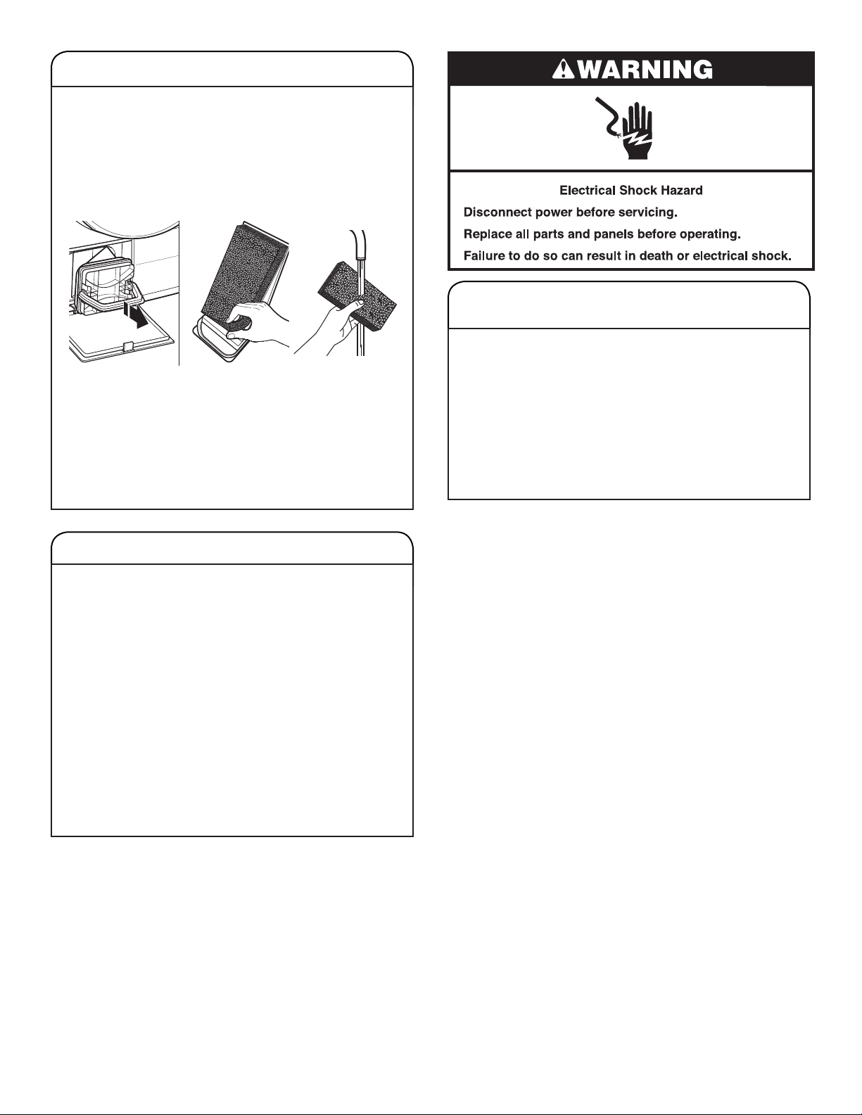
3. Clean bottom lter
Clean the bottom filter after every 5 cycles. Open the filter
door on the bottom of the dryer and grab the handle to pull
out filter. Remove the foam from the bottom filter. Clean the
filter foam and filter by hand or rinse with water – do not
wash the filter foam in a washer. Wring out the filter foam –
do not insert it in the bottom filter dripping wet. For additional
cleaning information, see “Dryer Care.”
Replace the filter foam on the bottom filter. Replace the
bottom filter in the filter chamber. Fold the filter handle down
and close the bottom door.
NOTE: To turn off the “Clean bottom filter” (
) status
indicator, the filter must be removed and replaced with the
Power button touched ON and no cycle running.
10
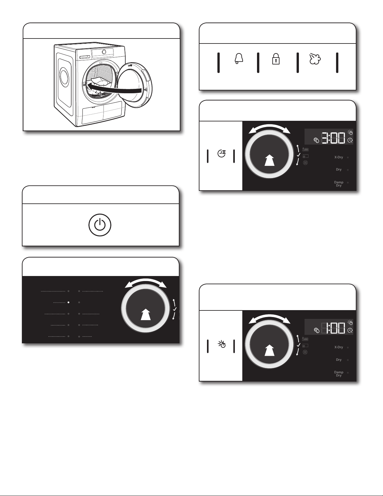
5. Touch Power button to turn on dryer
4. Load dryer
Open the door by pulling on the handle. Place laundry
in the dryer. Add a dryer sheet to wet load if desired.
Close the door.
IMPORTANT: Do not tightly pack the dryer. Items need
to tumble freely. Tightly packing can lead to poor drying
performance and may increase wrinkling and tangling.
6. Select program/cycle
Turn the knob to select a program/cycle for your laundry load.
As you turn the knob, an indicator light will light up next to
the program/cycle names to the left of the knob. Stop turning
when the indicator next to the desired program/cycle lights up.
Press the knob to confirm your selection.
See “Program/Cycle Guide” for details on program/cycle
features.
Mixed
Heavy Duty
Normal
Synthetics
Delicates
Wool
Air Dry
Refresh
Timed Dry
Bulky/Bedding
Cycle
Signal
Control
Lock
Hold 3 Sec
Steam
7. Select options, if desired
ool
y
esh
y
edding
X-Dry
Dry
Damp
Dry
Delay
Start
8. Setting a delayed start, if desired
If you do not want to begin a cycle immediately, you may
choose the Delay Start option. This will delay the start
of the drying cycle by up to 23 hours.
To set a Delayed Start:
1. Touch the Delay Start button to set the desired delay time.
2. Turn the knob to the number of hours you want to delay
the start of the drying cycle. The delay time will appear
on the display. Press the knob to confirm your selection.
After touching the Start/Pause button, the time will count
down until the delay time has been reached. The dryer will
start and the display will show the remaining time in the cycle.
ool
y
esh
y
edding
X-Dry
Dry
Damp
Dry
Timed
Dry
9. If Air Dry or Timed Dry was selected,
set drying time
When you select a timed cycle, the indicator light above
“Timed Dry” lights up. Turn the knob to select the desired
time, up to 180 minutes. Press the knob to confirm your
selection.
11
14. Remove garments promptly
after cycle is nished
Promptly remove garments after cycle has completed
to reduce wrinkling.
Wool
Air Dry
Refresh
imed Dry
edding
Options
X-Dry
Dry
Damp
Dry
11. Select any additional options
*
After setting drying time or dryness level, the indicator light
above “Options” lights up. Turn the knob to select the desired
option(s). As you turn the knob, the option symbols above the
Options button will light up one at a time as you turn the knob.
Stop turning when the symbol of the desired option lights up.
Press the knob to confirm your selection.
*
Not all options and settings are available with all program/
cycles. See “Program/Cycle Guide” for available options
and settings.
When the display indicates that the cycle has finished, touch
the Power button to turn off the dryer. Open the door and take
out your laundry.
To save energy, the dryer turns off automatically about
a quarter hour after the program/cycle ends.
If not turned off right after the program/cycle ends, the
dryer will tumble the laundry for about 10 minutes to prevent
wrinkling. The display shows an animation.
NOTE: If the Power button is touched and held, a countdown
will be displayed. At the end of the countdown, any errors will
be erased and the program/cycle will restart.
12. Touch Start/Pause button to begin
drying program/cycle
Touch the Start/Pause button to start the drying program/
cycle. To pause a program/cycle in progress, touch the Start/
Pause button once, then touch again to continue the program/
cycle. To cancel a program/cycle, touch the Power button.
13. Touch Power button to turn off
dryer after program/cycle ends
Adapting the dryer to water conductivity
The drying results are affected by the conductivity of the water
used during washing. If, by modifying the available dryness
levels (damp dry, dry, and extra dry), you are not satisfied with
the final drying results, you can adapt the water conductivity
level. The dryer comes with preset level 3. Choose between
level 1 (most damp results) and 5 (most dry results).
1. Touch and hold the Program button. The
display will count down until the Conductivity
Adjustment symbol on the display flashes
and the current setting is shown.
2. Turn the knob to adjust the level (1-2-3-4-5). Press the
knob to confirm your selection.
NOTE: This new setting will affect all future cycles. If the
desired drying results are attained, water conductivity will
not require further adjustment.
ool
y
esh
y
edding
X-Dry
Dry
Damp
Dry
Dryness
Level
10. If an automatic cycle was selected,
set dryness level
When you select an automatic cycle, the indicator light above
“Dryness Level” lights up. Turn the knob to select the desired
level. As you turn the knob, an indicator light will light up next
to the dryness levels to the right of the knob. Stop turning
when the indicator next to the desired level lights up. Press
the knob to confirm your selection.
P
Program
3 Sec
12
Dryer Care
CLEANING THE DRYER LOCATION
Keep dryer area clear and free from items that would
block the airflow for proper dryer operation. This includes
clearing piles of laundry in front of the dryer.
CLEANING THE DRYER INTERIOR
To clean dryer drum:
1. Use a mild hand dish detergent mixed at a low
concentration with very warm water, and rub with
a soft cloth.
2. Rinse well with a wet sponge or towel.
3. Tumble a load of clean clothes or towels to dry drum
OR
Use a microfiber cloth and hot water in a spray bottle
to clean the drum and a second microfiber towel to dry.
REMOVING ACCUMULATED LINT
From Inside the Dryer Cabinet
Lint should be removed every 2 years, or more often,
depending on dryer usage. Cleaning should be done
by a qualified appliance servicer.
CLEANING THE LINT SCREEN
Clean lint screen after every load.
The lint screen is located in the door opening of the dryer.
A screen blocked by lint can increase drying time.
To clean:
1. Pull the lint screen straight up and out. Press tab down
and open lint screen. Roll lint off the screen with your
fingers.
2. Push the lint screen firmly back into place.
IMPORTANT:
n
Do not run the dryer with the lint screen loose,
damaged, blocked, or missing. Doing so can cause
overheating and damage to both the dryer and fabrics.
As-needed cleaning
Laundry detergent and fabric softener residue can build
up on the lint screen. This buildup can cause longer drying
times for your clothes, or cause the dryer to stop before
your load is completely dry.
Clean the lint screen with a nylon brush every 6 months,
or more frequently, if it becomes clogged due to a residue
buildup.
To wash lint screen:
1. Roll lint off the screen with
your fingers.
2. Wet both sides of lint screen
with hot water.
3. Wet a nylon brush with hot water
and liquid detergent. Scrub lint
screen with the brush to remove
residue buildup.
4. Rinse screen with hot water.
5. Thoroughly dry lint screen with
a clean towel. Reinstall screen
in dryer.
13
CLEANING THE BOTTOM FILTER
Clean bottom filter after every 5 loads.
The filter is located in bottom corner of dryer.
1. Open the filter door on the bottom of the dryer and grab
the handle to pull out the filter. Remove the foam from
the bottom filter. Clean the filter foam and the filter by
hand or rinse with water – do not wash the filter foam
in a washer. Wring out the filter foam – do not insert
it in the bottom filter dripping wet.
2. Replace the filter foam on the bottom filter. Replace the
bottom filter in the filter chamber. Fold the filter handle
down and close the bottom door.
IMPORTANT:
n
Do not run the dryer with the filter loose, damaged,
blocked, or missing. Doing so can cause overheating
and damage to both the dryer and fabrics.
NON-USE, STORAGE, AND MOVING CARE
Non-Use or Storage Care
If you will be on vacation or not using your dryer for an
extended period of time, you should:
1. Empty water tank.
2. Unplug dryer or disconnect power.
3. Clean lint screen. See “Cleaning the Lint Screen.”
4. In colder climates, store your dryer where it will not
freeze. Because some water may stay in the hose,
freezing can damage your dryer.
Moving Care
For power supply cord-connected dryers:
1. Empty water tank.
2. Unplug the power supply cord.
3. Make sure leveling legs are secure in dryer base.
4. Use tape to secure dryer door.
NON-USE, STORAGE, AND
MOVING CARE (cont.)
For direct-wired dryers:
1. Empty water tank.
2. Disconnect power.
3. Disconnect wiring.
4. Make sure leveling legs are secure in dryer base.
5. Use tape to secure dryer door.
Reinstalling the Dryer
Follow the “Installation Instructions” section to locate, level,
and connect the dryer.
14
INSTALLATION INSTRUCTIONS
Installation Requirements
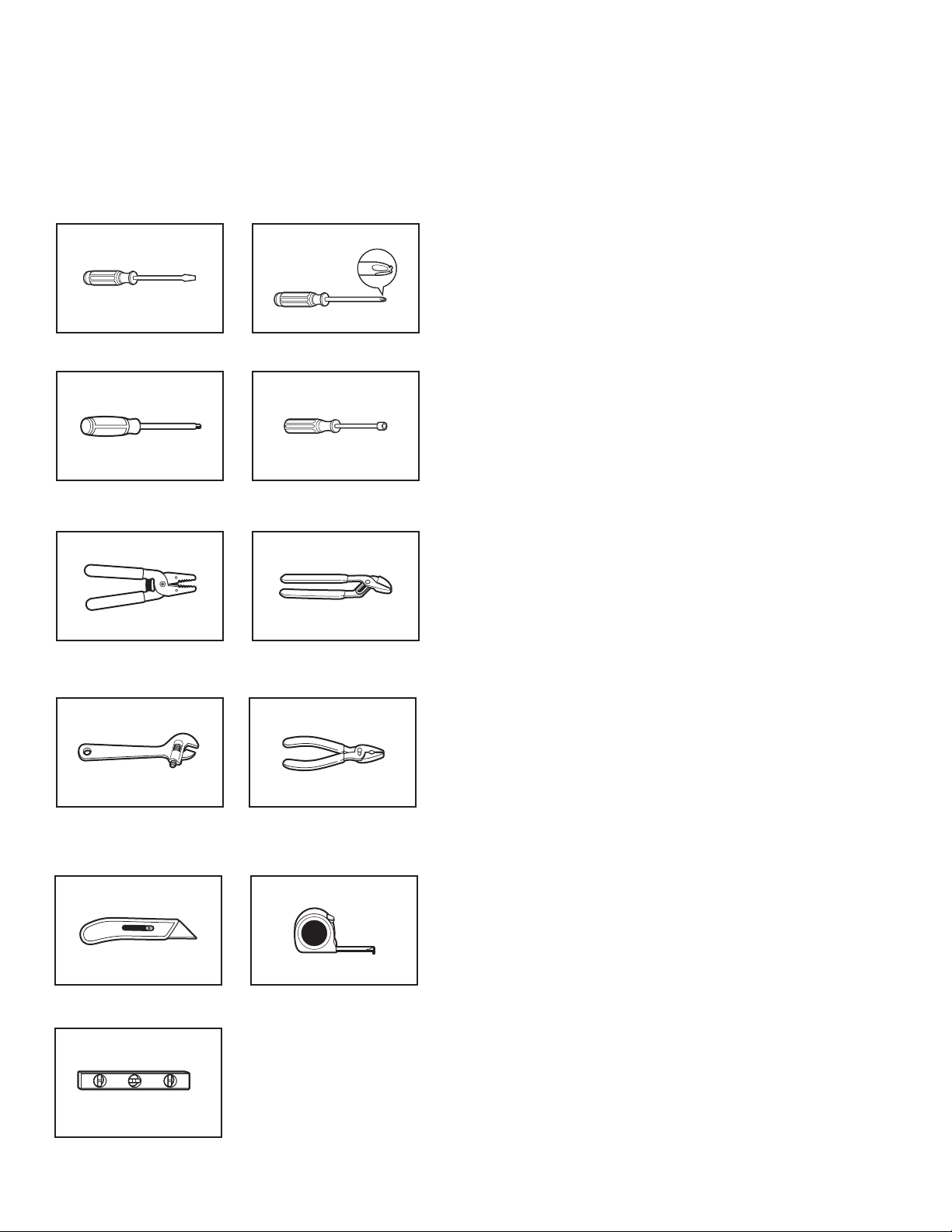
TOOLS AND PARTS
Gather the required tools and parts before starting installation.
Tools needed:
Flat-blade screwdriver #2 Phillips screwdriver
Wire stripper (direct wire
installations)
Channel locks
Adjustable wrench that
opens to 1" (25 mm) or
hex-head socket wrench
1/4" and 5/16" nut driver
(recommended)
Utility knife Tape measure
Level
Pliers
If using a power supply cord:
Use a UL-listed power supply cord kit marked for use with
clothes dryers. The kit should contain:
n A UL-listed 30-amp power supply cord, rated 120-/240-volt
minimum. The cord should be type SRD or SRDT and
be at least 4 ft. (1.22 m) long. The wires that connect to
the dryer must end in ring terminals or spade terminals
with upturned ends.
Additional Accessories: (Not supplied with dryer)
Refer to “Operating Instructions” for information about
accessories available for your dryer.
Min. 8" long TORX
®
T20
®†
screwdriver
†® TORX and T20 are registered trademarks of Acument Intellectual Properties, LLC.
15
Location Requirements
Check code requirements. Some codes limit, or do not permit,
installing dryer in garages, closets, mobile homes, or sleeping
quarters. Contact your local building inspector.
You will need:
n A separate 30-amp circuit.
n If using power supply cord, a grounded electrical outlet
located within 2 ft. (610 mm) of either side of dryer.
See “Electrical Requirements.”
n Floor must support dryer weight of 200 lbs. (90.7 kg).
Also consider weight of companion appliance.
n Level floor with maximum slope of 1" (25 mm) under entire
dryer. If forward slope is greater than 1" (25 mm), water
could run out from front of filter. If not level, clothes may
not tumble properly and automatic sensor cycles may
not operate correctly.
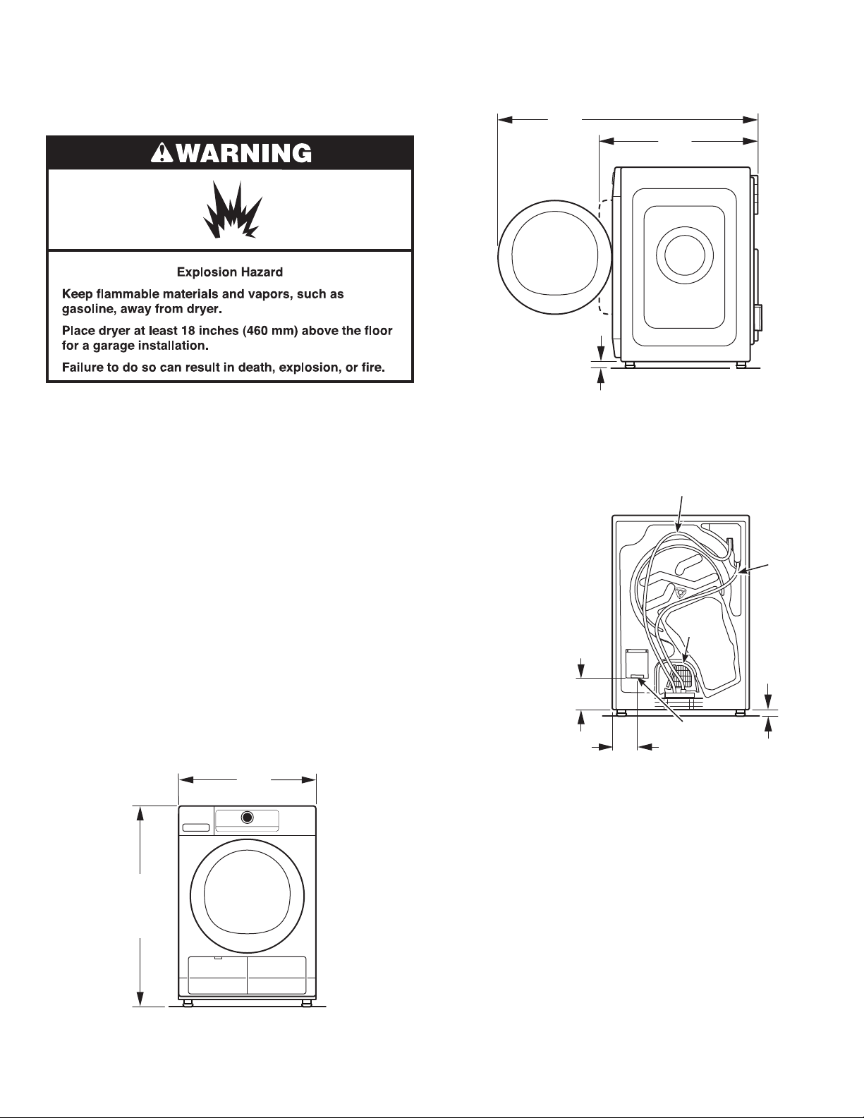
n For garage installation, place dryer at least 18" (460 mm)
above floor. If using a pedestal, you will need 18" (460 mm)
to bottom of dryer.
IMPORTANT: Do not operate, install, or store dryer where
it will be exposed to water, weather, or at temperatures below
40°F (4°C). Lower temperatures may cause dryer not to shut
off at end of automatic sensor cycles, resulting in longer
drying times.
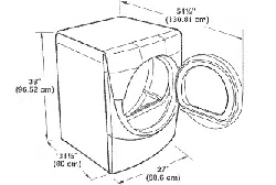
DRYER DIMENSIONS
33
1
/2" Min.
(851 mm)
33
3
/4" Max.
(857 mm)
24"
(610 mm)
Front view:
Side view:
Back view:
7
1
/4 "
(184 mm)
4"
(102 mm)
3
/4"
(18 mm)
NOTES:
n Allow clearance
behind dryer for
proper drain hose
routing and cooling
fan ventilation. Push
dryer back as far as
possible and make
sure drain hose
is not crushed
or kinked.
n Water can be
drained into an
alternate location.
Remove the top
end of the white
hose from the water
tank and install,
for example, in
a floor standpipe
(see “Drain
System”).
Grey
water
drain
Cooling
fan
IMPORTANT: Do not block cooling fan as your dryer may not
operate properly.
Power cord/
cable
24"
(610 mm)
41
1
/2"
(1054 mm)
24"
(610 mm)
3
/4"
(18 mm)
43
5
⁄16"
(1100 mm)
26"
(654 mm)
White hose from pump
to water tank
33
1
⁄2" Min.
(851 mm)
34
1
⁄2" Max.
(876 mm)
16
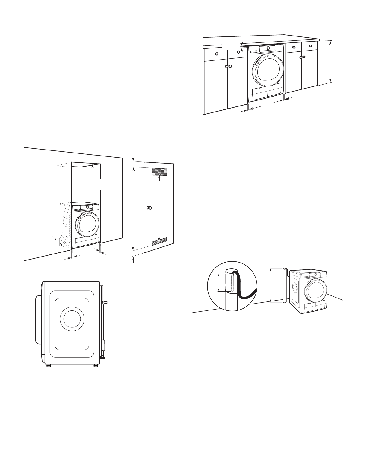
Installation spacing for recessed area
or closet installation
All dimensions show recommended and minimum spacing
allowed.
n Additional spacing should be considered for ease of
installation and servicing.
n Additional clearances might be required for wall, door,
floor, moldings, and drain system.
n Additional spacing should be considered on all sides
of the dryer to reduce noise transfer.
n For closet installation with a door, minimum ventilation
openings in the top and bottom of the door are required.
Louvered doors with equivalent ventilation openings are
acceptable.
n Companion appliance spacing should also be considered.
Recommended installation clearances (dryer only):
Mobile home – Additional installation requirements:
This dryer is suitable for mobile home installations.
The installation must conform to the Manufactured
Home Construction and Safety Standard, Title 24 CFR,
Part 3280 (formerly the Federal Standard for Mobile
home construction and Safety, Title 24, HUD Part 280)
or Standard CAN/CSA-Z240 MH.
18" min.
(457 mm)
1"
(25 mm)
0" - 5"*
(0 mm - 127 mm)
24 in.
2
min.
(155 cm
2
)
48 in.
2
min.
(310 cm
2
)
3"
(76 mm)
3"
(76 mm)
1"
(25 mm)
*NOTE: 0"–5"
(0 mm–127 mm)
spacing is allowed
behind dryer, providing
drain hose is not kinked
or pinched.
Drain System
Minimum diameter for a standpipe drain: 2" (51 mm). Top of
standpipe must be at least 30" (762 mm) high; install no higher
than 36" (910 mm) from bottom of dryer.
Floor standpipe drain system
Drain system can be installed by routing the white hose to
a floor drain, wall standpipe, floor standpipe, or laundry tub
instead of to the water tank. Select the method you need.
IMPORTANT: To avoid siphoning, only 4.5" (114 mm) of drain
hose should be inside standpipe; do not force excess hose
into standpipe. Always secure drain hose with a cable tie
(not supplied).
4.5"
(114 mm)
4.5"
(114 mm)
max. 48"
(1219 mm)
min. 30"
(762 mm)
Custom under-counter installation:
34
1
⁄2" Min.
(876 mm)
1" Min.
(25 mm)
1" Min.
(25 mm)
max. 36"
(910 mm)
min. 30"
(762 mm)
0" Min.
(0 mm)
17
Electrical Requirements –
U.S.A. Only
It is your responsibility:
n To contact a qualified electrical installer.
n To be sure that the electrical connection is adequate and
in conformance with the National Electrical Code, ANSI/
NFPA 70 – latest edition and all local codes and ordinances.
The National Electrical Code requires a 4-wire power supply
connection for homes built after 1996, dryer circuits involved
in remodeling after 1996, and all mobile home installations.
A copy of the above code standards can be obtained from:
National Fire Protection Association, One Batterymarch Park,
Quincy, MA 02269.
n To supply the required 3- or 4-wire, single-phase,
120-/240-volt, 60 Hz, AC-only electrical supply (or 3- or
4-wire, 120/208-volt electrical supply, if specified on the
serial/rating plate) on a separate 30-amp circuit, fused
on both sides of the line. Connect to an individual branch
circuit. Do not have a fuse in the neutral or grounding circuit.
n Do not use an extension cord.
n If codes permit and a separate ground wire is used, it is
recommended that a qualified electrician determine that
the ground path is adequate.
Electrical Connection
To properly install your dryer, you must determine the type
of electrical connection you will be using and follow the
instructions provided for it here.
n This dryer is manufactured ready to install with a 3-wire
electrical supply connection. A neutral ground conductor
(white wire) is provided between the power supply neutral
connection (center terminal) and the dryer external
grounding point (green screw). If the dryer is installed with
a 4-wire electrical supply connection, one end of the neutral
ground conductor must be removed from the external
ground connector (green screw), and secured under the
neutral terminal (center screw) of the terminal block. When
both ends of the neutral ground conductor are secured
under the neutral terminal (center or white wire) of the
terminal block, the dryer cabinet is isolated from the neutral
conductor. The green ground wire of the 4-wire power cord
must be secured to the dryer cabinet with the green ground
screw.
n If local codes do not permit the connection of a neutral
ground wire to the neutral wire, see “Optional External
Ground 3-wire connection”.
n A 4-wire power supply connection must be used when the
appliance is installed in a location where grounding through
the neutral conductor is prohibited. Grounding through the
neutral is prohibited for (1) new branch-circuit installations
after 1996, (2) mobile homes, (3) recreational vehicles, and
(4) areas where local codes prohibit grounding through the
neutral conductors.
If using a power supply cord:
Use a UL-listed power supply cord kit marked for use with
clothes dryers. The kit should contain:
n A UL-listed 30-amp power supply cord, rated 120/240-volt
minimum. The cord should be type SRD or SRDT and be
at least 4 ft. (1.22 m) long. The wires that connect to
the dryer must end in ring terminals or spade terminals
with upturned ends.
If connecting by direct wire:
Power supply cable must match power supply (4-wire or 3-wire)
and be:
n Flexible armored cable or nonmetallic sheathed copper
cable (with ground wire), covered with flexible metallic
conduit. All current-carrying wires must be insulated.
n 10-gauge solid copper wire (do not use aluminum) at least
5 ft. (1.52 m) long.
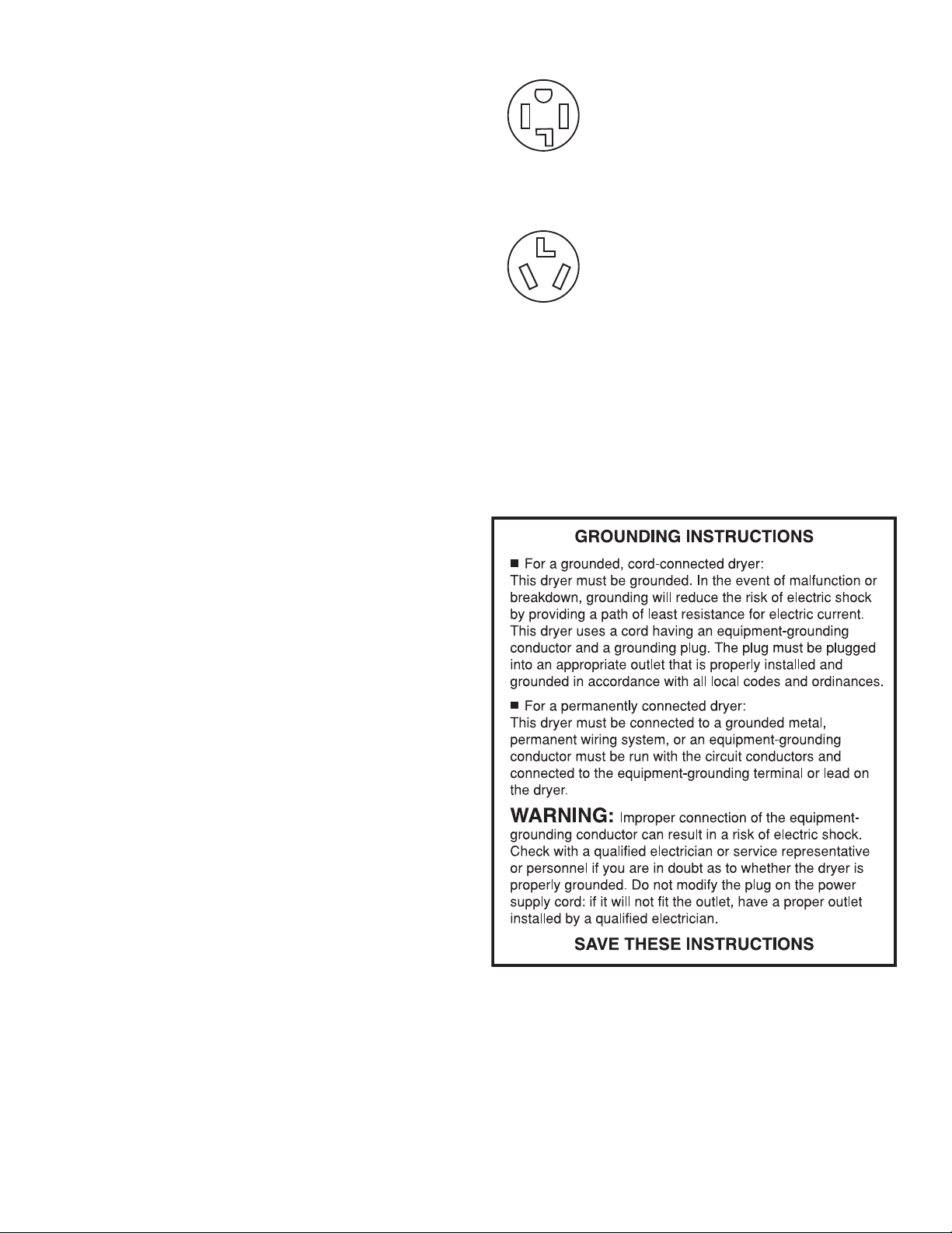
Then choose a 4-wire power supply cord with
ring or spade terminals and UL-listed strain
relief. The 4-wire power supply cord, at least
4 ft. (1.22 m) long, must have four 10-gauge
copper wires and match a 4-wire receptacle
of NEMA-Type 14-30R. The ground wire
(ground conductor) may be either green
or bare. The neutral conductor must be
identified by a white cover.
Then choose a 3-wire power supply cord with
ring or spade terminals and UL-listed strain
relief. The 3-wire power supply cord, at least
4 ft. (1.22 m) long, must have three 10-gauge
copper wires and match a 3-wire receptacle
of NEMA-Type 10-30R.
4-wire
receptacle
(14-30R)
3-wire
receptacle
(10-30R)
If your outlet looks like this:
18
Electric Dryer Power Hookup –
Canada Only
Electrical Requirements
It is your responsibility:
n To contact a qualified electrical installer.
n To be sure that the electrical connection is adequate
and in conformance with the Canadian Electrical Code,
C22.1 – latest edition and all local codes. A copy of the
above codes standard may be obtained from: Canadian
Standards Association, 178 Rexdale Blvd., Toronto, ON
M9W 1R3 CANADA.
n To supply the required 4-wire, single-phase, 120/240-volt,
60 Hz., AC-only electrical supply on a separate 30-amp
circuit, fused on both sides of the line. A time-delay fuse
or circuit breaker is recommended. Connect to an individual
branch circuit.
n This dryer is equipped with a CSA
International Certified Power Cord intended
to be plugged into a standard 14-30R wall
receptacle. The cord is 5 ft. (1.52 m) in
length. Be sure wall receptacle is within
reach of dryer’s final location.
n Do not use an extension cord.
If using a replacement power supply cord, it is recommended
that you use Power Supply Cord Replacement Part Number
8579325. For further information, please reference the
“Assistance or Service” section.
GROUNDING INSTRUCTIONS
SAVE THESE INSTRUCTIONS
■
For a grounded, cord-connected dryer:
This dryer must be grounded. In the event of malfunction or
breakdown, grounding will reduce the risk of electric shock
by providing a path of least resistance for electric current.
This dryer is equipped with a cord having an equipment-
grounding conductor and a grounding plug. The plug must
be plugged into an appropriate outlet that is properly
installed and grounded in accordance with all local codes
and ordinances.
WARNING: Improper connection of the equipment-
grounding conductor can result in a risk of electric shock.
Check with a qualified electrician or service representative
or personnel if you are in doubt as to whether the dryer is
properly grounded. Do not modify the plug provided with
the dryer: if it will not fit the outlet, have a proper outlet
installed by a qualified electrician.
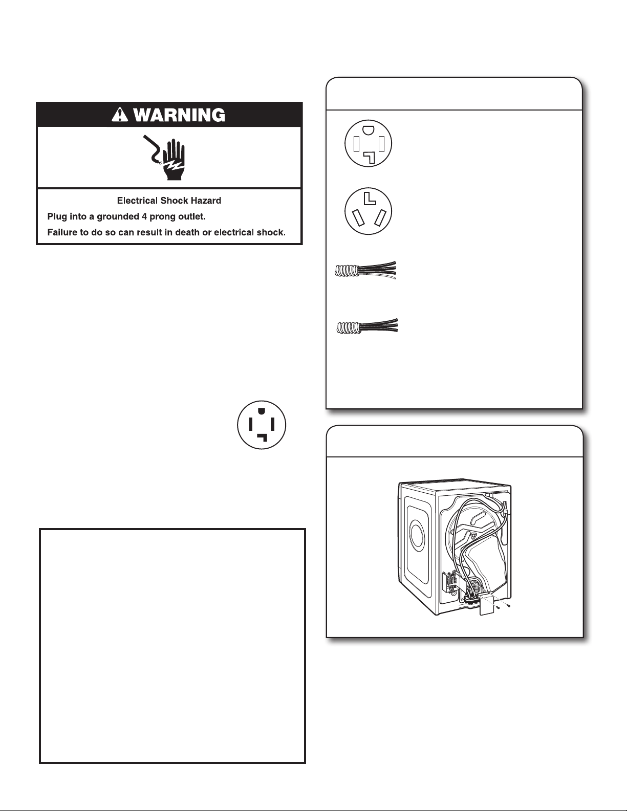
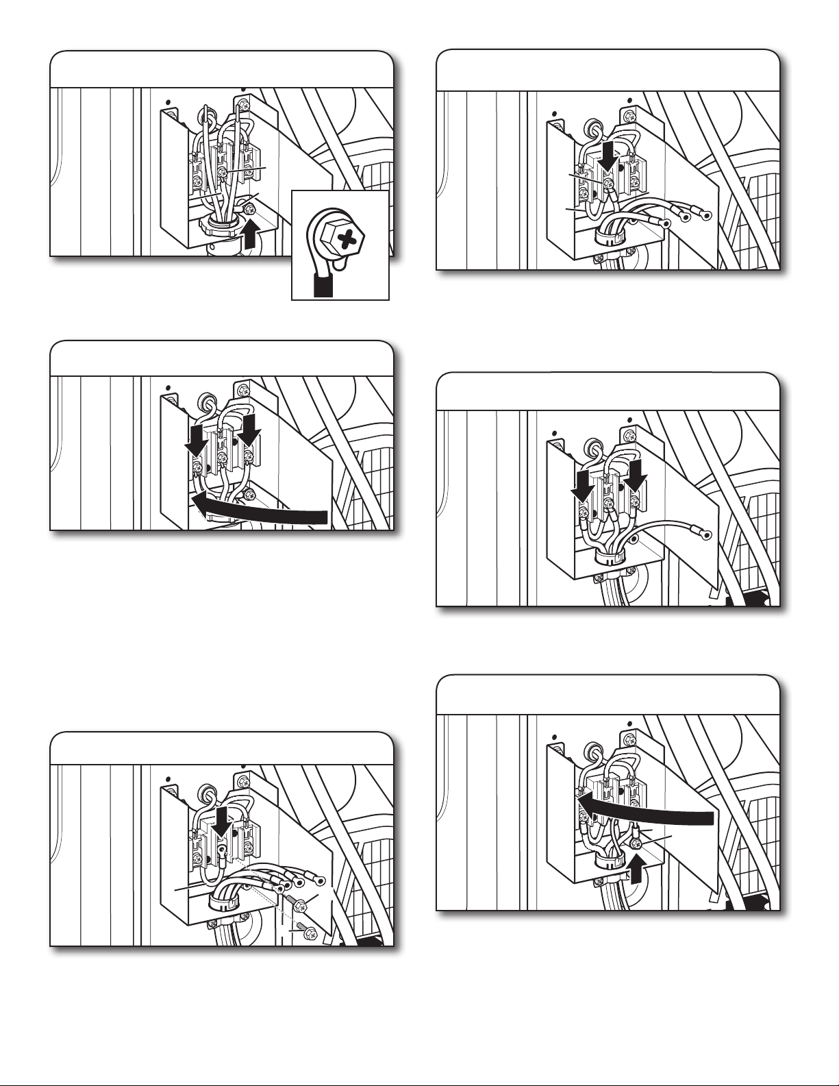
Electric Installation – U.S.A. Only
Remove hold-down screws and terminal block cover.
1. Choose electrical connection type
Power supply cord 4-wire receptacle
(NEMA-Type 14-30R):
Go to “Power Supply Cord Connection.”
3-wire direct connection:
Go to “Direct Wire Connection.”
4-wire direct connection:
Go to “Direct Wire Connection.”
Power supply cord 3-wire receptacle
(NEMA Type 10-30R):
Go to “Power Supply Cord Connection.”
NOTE: If local codes do not permit connection of a
cabinet-ground conductor to neutral wire, go to “Optional
External Ground for 3-Wire Connection.” This connection
can be used with either a power supply cord or a direct
wire connection.
2. Remove terminal block cover
Before you start: disconnect power.
4-wire receptacle
(14-30R)
19
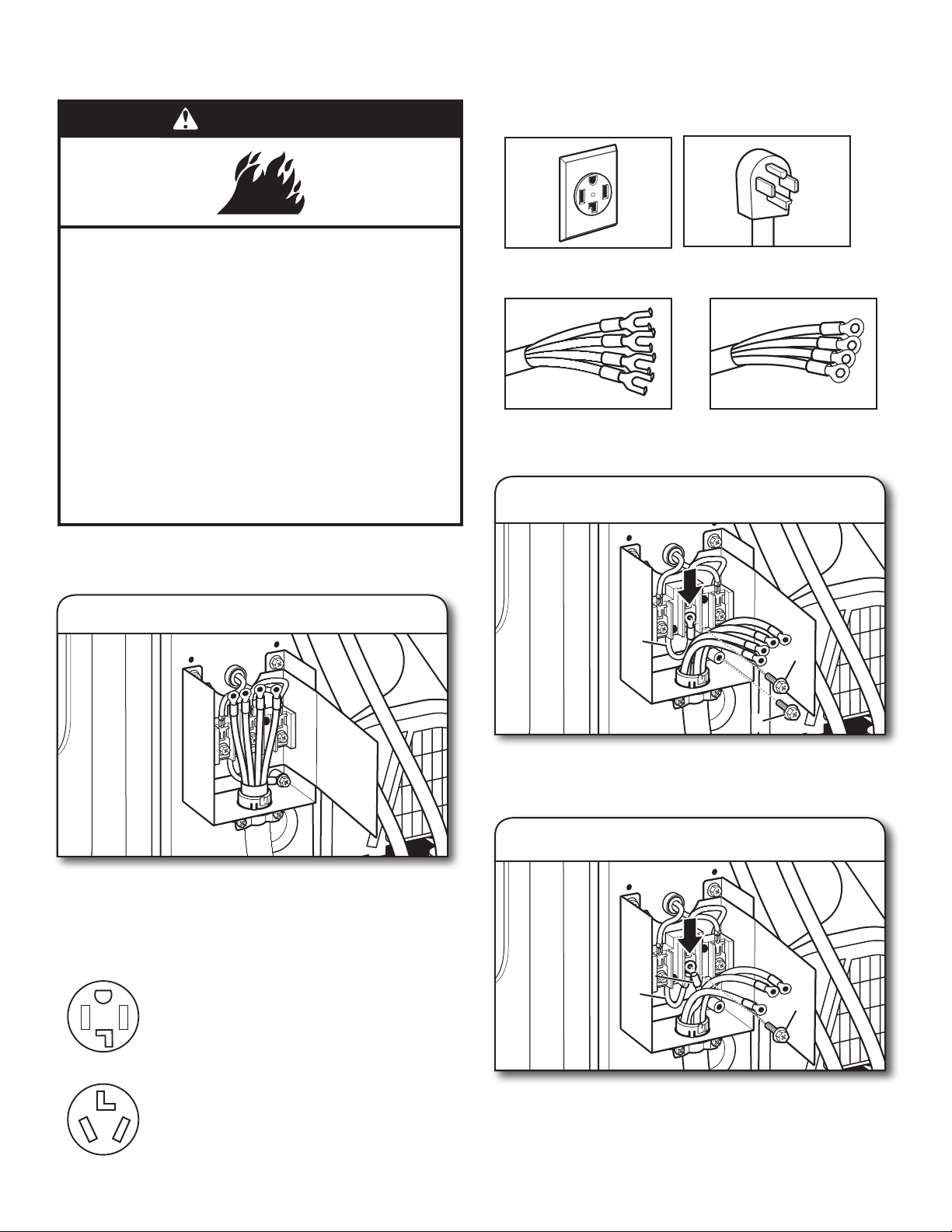
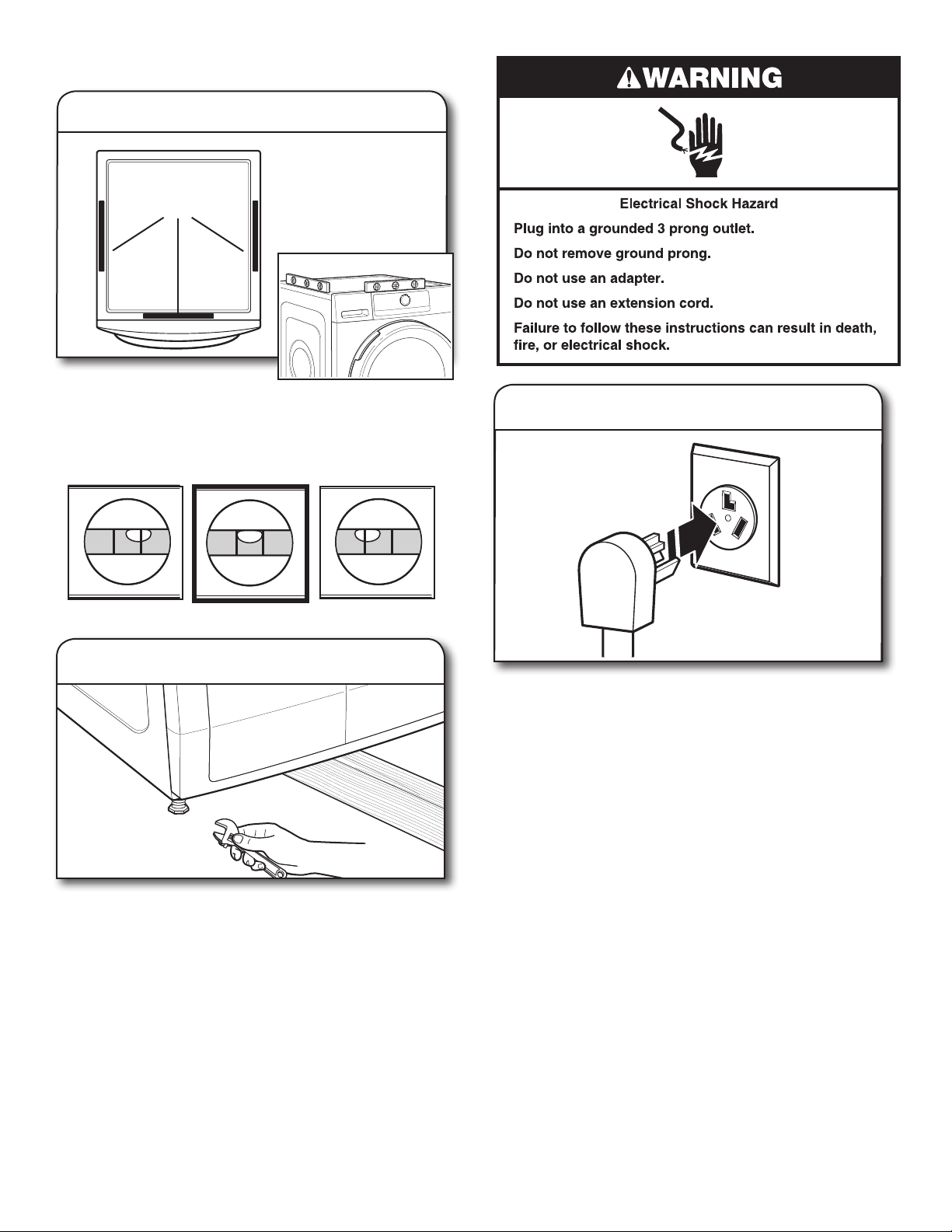
WARNING
Fire Hazard
Use a new UL listed 30 amp power supply cord.
Use a UL listed strain relief.
Disconnect power before making electrical connections.
Connect neutral wire (white or center wire) to center
terminal.
Ground wire (green or bare wire) must be connected to
green ground connector.
Connect remaining 2 supply wires to remaining
2 terminals.
Securely tighten all electrical connections.
Failure to do so can result in death, fire, or
electrical shock.
4-Wire Power Supply Cord Strain Relief:
IMPORTANT: Use the strain relief supplied with the dryer.
Power Supply Cord Connection
4-Wire Power Supply Cord Connection
IMPORTANT: A 4-wire connection is required for mobile
homes and where local codes do not permit the use
of 3-wire connections.
4-wire receptacle
(NEMA-type 14-30R)
4 prong plug
Spade terminals with
upturned ends
Ring terminals
Attach power supply cord to strain relief
Put power supply cord through the strain relief. Be sure that
the wire insulation on the power supply cord is inside the
strain relief. Do not further tighten strain relief screws at
this point.
Power supply cord 4-wire receptacle
(NEMA-Type 14-30R):
Go to “4-Wire Power Supply Cord
Connection.”
Power supply cord 3-wire receptacle
(NEMA-Type 10-30R):
Go to “3-Wire Power Supply Cord
Connection.”
If your outlet looks like this:
Connect neutral wire (white or center) (C) of power supply cord
under center terminal block screw (B). Make sure the end of
neutral bonding wire (white) (D) looped in Step 1 remains on
the center terminal when the power supply cord neutral wire is
attached. Tighten screw.
Remove center terminal block screw (B) and green external
ground conductor screw (A). Loop neutral bonding wire (white)
(D) to center terminal block.
2. Connect neutral wire
C
1. Prepare to connect neutral wire
D
B
D
A
B
20
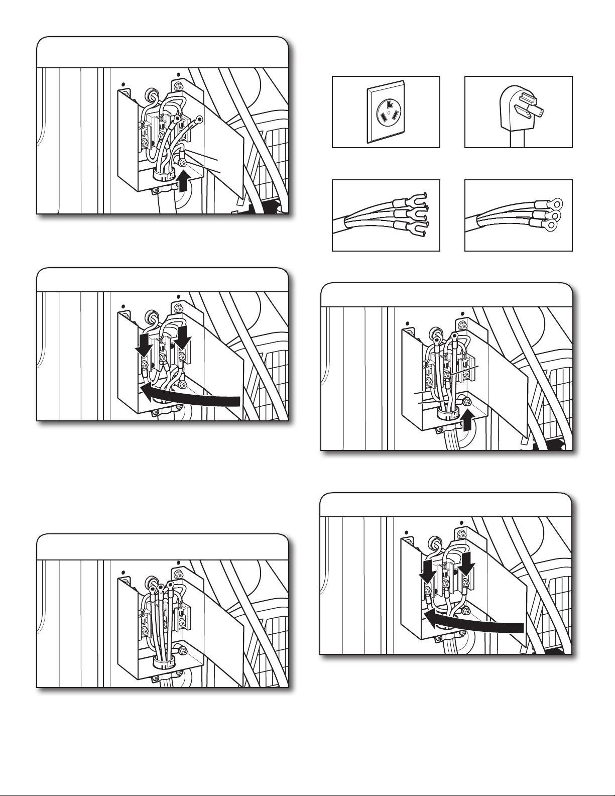
3-wire receptacle
(NEMA-type 10-30R)
3 prong plug
Spade terminals with
upturned ends
Ring terminals
4. Connect remaining wires
Connect remaining wires under outer terminal block screws.
Tighten screws, tighten strain relief screws, and fold insulator
over terminal block. Finally, reinsert tab of terminal block cover
into slot at bottom edge of terminal block housing. Secure
cover with the 2 hold-down screws. Now, go to “Level Dryer.”
3-Wire Power Supply Cord Connection
Use where local codes permit connecting cabinet-ground
conductor to neutral wire.
2. Connect remaining wires
Connect remaining wires under outer terminal block
screws. Tighten screws, tighten strain relief screws,
and fold insulator over terminal block. Finally, reinsert
tab of terminal block cover into slot at bottom edge
of terminal block housing. Secure cover with the
2 hold-down screws. Now, go to “Level Dryer.”
Connect neutral (center) wire (C) of power supply cord
under
center terminal block screw (B)
. Tighten screw.
3-Wire Power Supply Cord Strain Relief:
IMPORTANT: Use the strain relief supplied with the dryer.
Attach power supply cord to strain relief
Put power supply cord through the strain relief. Be sure that
the wire insulation on the power supply cord is inside the
strain relief. Do not further tighten strain relief screws at
this point.
Connect ground wire (F) (green or bare) of power supply
cord under green external ground conductor screw (A).
Tighten screw.
3. Connect ground wire
F
A
1. Connect neutral (center) wire
B
C
D
F
21
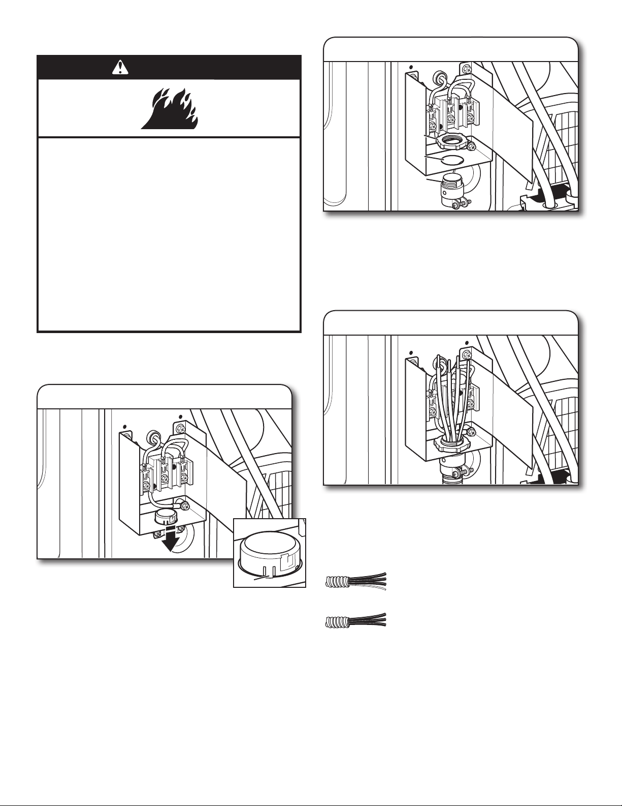
Direct Wire Connection
WARNING
Fire Hazard
Use 10 gauge copper wire.
Use a UL listed strain relief.
Disconnect power before making electrical connections.
Connect neutral wire (white or center wire) to center
terminal.
Ground wire (green or bare wire) must be connected to
green ground connector.
Connect remaining 2 supply wires to remaining
2 terminals.
Securely tighten all electrical connections.
Failure to do so can result in death, fire, or
electrical shock.
Direct Wire Strain Relief
IMPORTANT: Use a conduit strain relief (not supplied).
3. Attach direct wire cable to strain relief
Put direct wire cable through the strain relief. The strain
relief should have a tight fit with the dryer cabinet and be
in a vertical position. Tighten strain relief screw against the
direct wire cable.
3-wire direct connection:
Go to “3-Wire Direct Wire Connection.”
4-wire direct connection:
Go to “4-Wire Direct Wire Connection.”
If your wiring looks like this:
2. Attach direct wire strain relief
Unscrew the removable conduit connector (A) and any
screws from a 3/4" (19 mm) UL-listed strain relief (UL marking
on strain relief). Put the threaded section of the strain relief (C)
through the hole below the terminal block opening (B).
Reaching inside the terminal block opening, screw the
removable conduit connector (A) onto the strain relief
threads, and tighten securely.
C
B
A
1. Remove existing strain relief
With a flat-blade screwdriver, flatten the three
tabs on the band at the top of the strain relief.
Pull out strain relief.
Tab
22
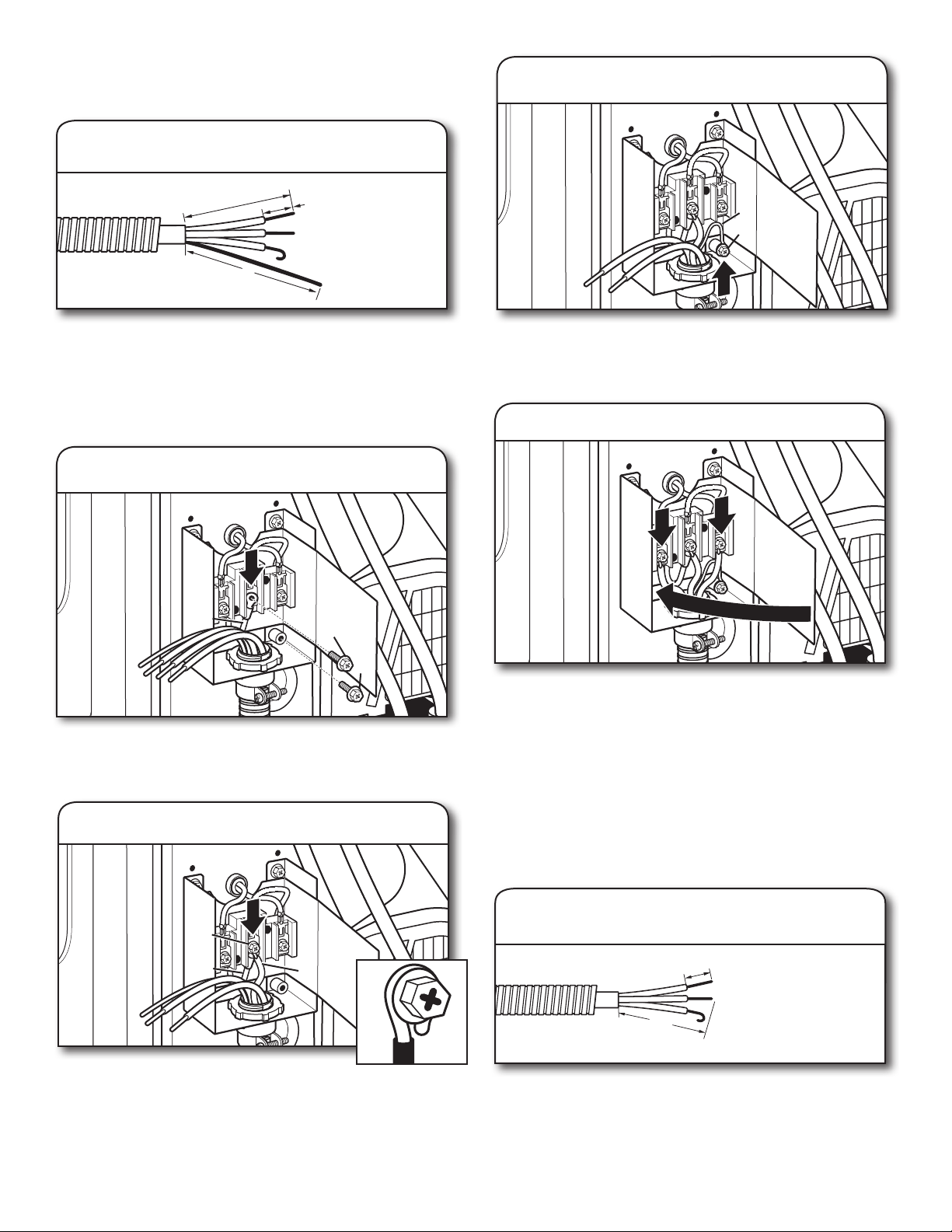
1. Prepare your 3-wire cable
for direct connection
1"
(25 mm)
3½"
(89 mm)
5. Connect remaining wires
Direct wire cable must have 5 ft. (1.52 m) of extra length so
dryer may be moved if needed.
Strip 3
1
/
2
" (89 mm) of outer covering from end of cable. Strip
insulation back 1" (25 mm). If using 3-wire cable with ground
wire, cut bare wire even with outer covering. Shape wire ends
into hooks.
Place hooked ends of remaining direct wire cable wires
under outer terminal block screws (hooks facing right).
Squeeze hooked ends together, tighten screws, tighten strain
relief screws, and fold insulator over terminal block. Finally,
reinsert tab of terminal block cover into slot at bottom edge
of terminal block housing. Secure cover with the 2 hold-down
screws. Now, go to “Level Dryer.”
3-Wire Direct Wire Connection
Use where local codes permit connecting cabinet-ground
conductor to neutral wire.
4-Wire Direct Wire Connection
IMPORTANT: A 4-wire connection is required for mobile homes
and where local codes do not permit 3-wire connections.
1. Prepare your 4-wire cable
for direct connection
1"
(25 mm)
3
1
⁄
2
"
(89 mm)
5"
(127 mm)
Direct wire cable must have 5 ft. (1.52 m) of extra length so
dryer may be moved if needed.
Strip 5" (127 mm) of outer covering from end of cable,
leaving bare ground wire at 5" (127 mm). Cut 1
1
/
2
" (38 mm)
from remaining 3 wires. Strip insulation back 1" (25 mm).
Shape ends of wires into hooks.
Remove center terminal block screw (B) and green external
ground conductor screw (A). Loop neutral bonding wire (white)
(D) to center terminal block.
Place hooked end (hook facing right) of neutral
wire (white or center wire) (C) of direct wire cable under center
screw of terminal block (B). Squeeze hooked ends together.
Make sure the end of neutral bonding wire (white) (D) looped
in Step 2 remains on the center terminal when the direct wire
cable neutral wire is attached. Tighten screw.
2. Prepare to connect neutral wire
B
D
A
3. Connect neutral wire
C
B
D
Connect ground wire (green or bare) (F) of direct wire cable
under green external ground conductor screw (A). Tighten
screw.
4. Connect ground wire
F
A
23
Place hooked end of neutral wire (white
or center) (C) of direct wire cable under
center screw of terminal block (B), hook
facing right. Squeeze hooked end together. Tighten screw.
3. Connect remaining wires
Place hooked ends of remaining direct wire cable wires
under outer terminal block screws (hooks facing right).
Squeeze hooked ends together, tighten screws, tighten strain
relief screws, and fold insulator over terminal block. Finally,
reinsert tab of terminal block cover into slot at bottom edge
of terminal block housing. Secure cover with the 2 hold-down
screws. Now, go to “Level Dryer.”
Optional External Ground for 3-Wire
Connection
(Power Supply Cord Shown)
IMPORTANT: You must verify with a qualified electrician
that this grounding method is acceptable before connecting.
Remove center terminal block screw (B) and green external
ground conductor screw (A). Loop neutral bonding wire (white)
(D) to center terminal block.
Connect neutral wire (white or center) (C) of power supply cord
or cable under center terminal block screw (B). Make sure
the end of neutral bonding wire (white) (D) looped in Step 1
remains on the center terminal when the power supply cord
neutral wire is attached. Tighten screw.
Place ends of remaining wires under outer terminal block
screws. Tighten screws and tighten strain relief.
3. Connect remaining wires
Connect a separate copper ground wire (G) under the green
external ground conductor screw (A) to an adequate ground.
Fold insulator over terminal block. Finally, reinsert tab of
terminal block cover into slot at bottom edge of terminal block
housing. Secure cover with the 2 hold-down screws. Now, go
to “Level Dryer.”
2. Connect neutral wire
C
B
D
1. Prepare to connect neutral wire
B
D
A
2. Connect neutral wire
C
B
D
4. Connect external ground wire
G
A
24
Level Dryer
1. Level dryer
Place
level here on
either side
Not Level LEVEL Not Level
Check levelness of dryer from
side to side. Repeat from front to back.
NOTE: The dryer must be level for the moisture-sensing
system to operate correctly. If forward slope of dryer is
greater than 1" (25 mm), water could run out from front
of filter.
2. Adjust leveling legs
If dryer is not level, prop up using a wood block, use wrench
to adjust legs up or down, and check again for levelness.
Once dryer is level, make sure all four legs are snug against
the floor and dryer does not rock.
3. Plug into a grounded 3 prong outlet
Complete Installation Checklist
q
Check that all parts are now installed. If there is an extra
part, go back through steps to see what was skipped.
q
Check that dryer is level. See “Level Dryer.”
q
Check that you have all of your tools.
q
Dispose of/recycle all packaging materials.
q
Check dryer’s final location.
q
Remove any tape remaining on dryer.
q
Wipe dryer drum interior thoroughly with a damp cloth
to remove any dust.
q
Read “Using Your Dryer” in “Operating Instructions.”
q
For power supply cord installation, plug into a grounded
outlet. For direct wire installation, turn on power.
q
Select a Timed Dry heated cycle and start dryer.
If dryer will not start, check the following:
• Controls are set in a running or ON position.
• Start/Pause button has been pushed firmly and held for
3 seconds.
• Dryer is plugged into an outlet and/or electrical supply.
• Household fuse is intact and tight or circuit breaker has
not tripped.
• Dryer door is closed.
This dryer automatically runs an installation diagnostic routine
at the start of its first cycle.
NOTE: You may notice an odor when dryer is first heated.
The odor will go away.
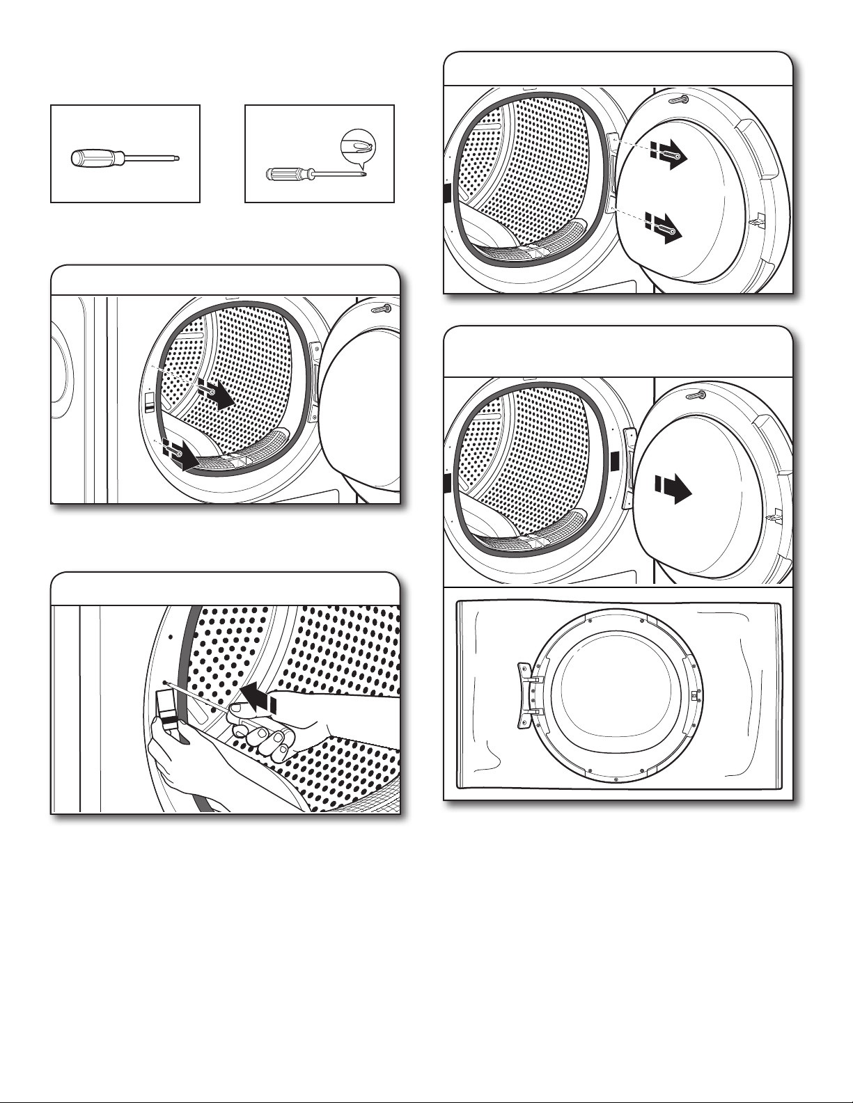
25
1. Remove door lock screws
#2 Phillips screwdriver
Min. 8" long TORX
®
T20
®
screwdriver
Tools needed:
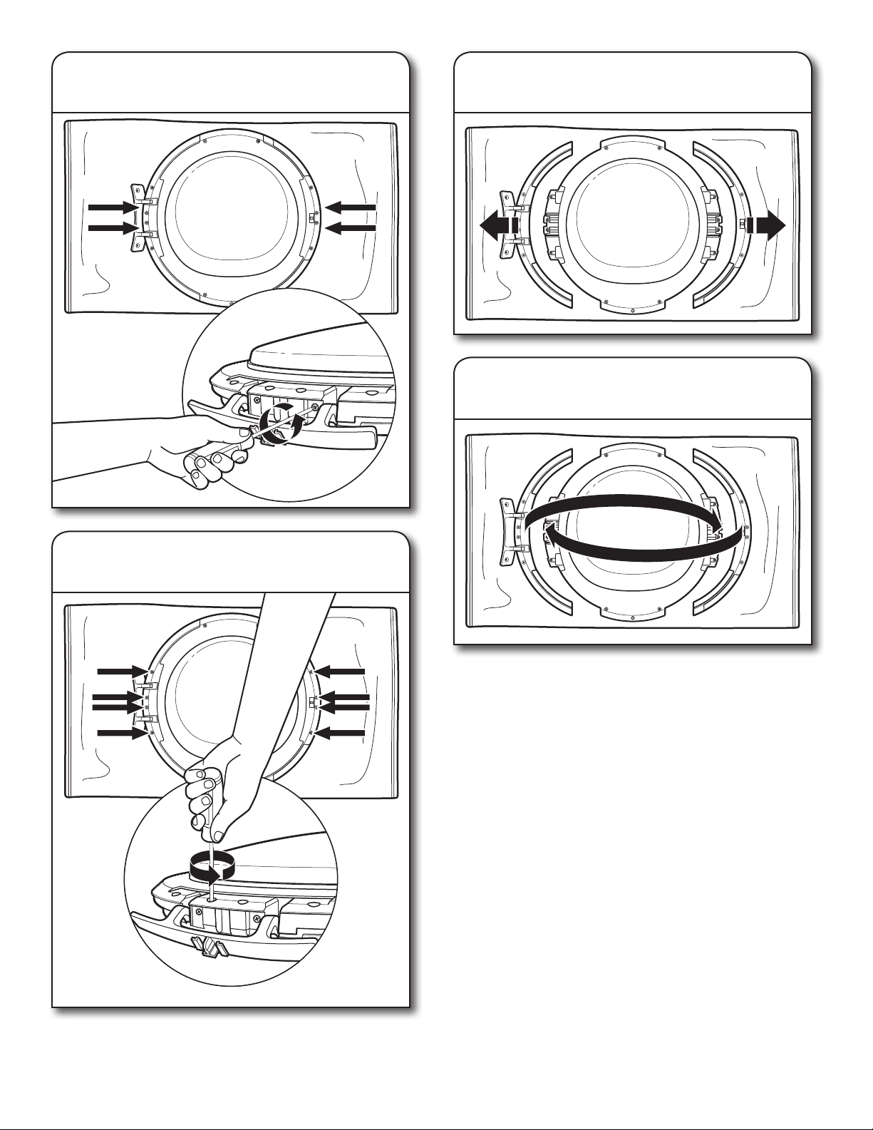
Door Reversal (optional)
2. Remove door lock
Press the small knob above the door lock with a small
screwdriver. At the same time, push up on the door lock
and pull it towards you.
3.
Remove two screws on door hinge
Remove the two trim screws located above and below
the door lock, to the left of the door opening.
4. Remove door and gently lay
front-side-down on soft surface
26
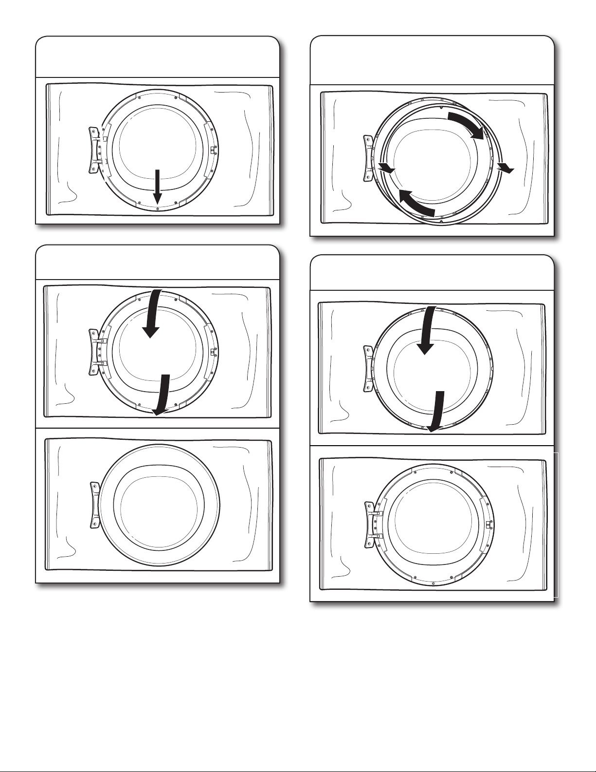
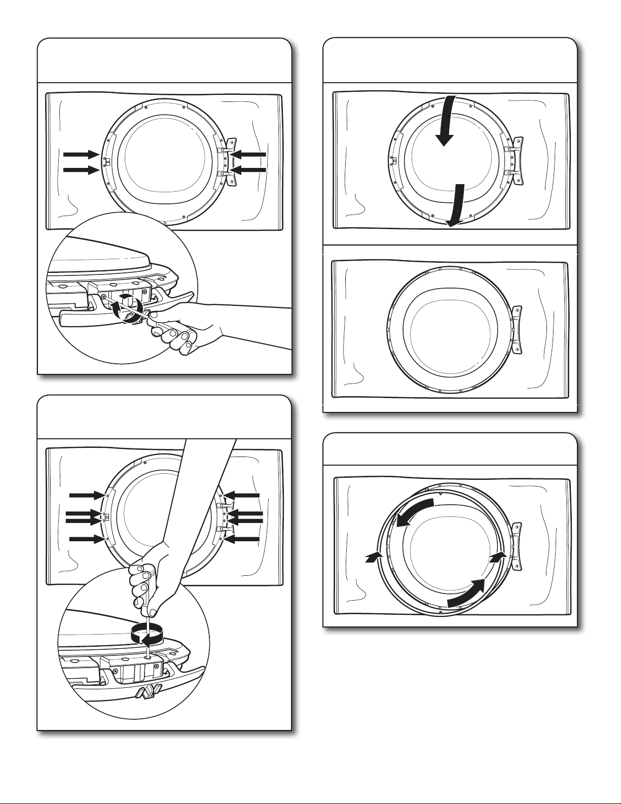
5. Unscrew bottom screw to release
chrome trim ring
6. Flip over door so door glass
is on bottom
8. Flip over door so door glass again
faces up
7. While holding door, gently turn
chrome trim ring clockwise and
remove
27
9. Remove 2 side screws on each side
of door
10. Remove 4 inner screws on each
side of door
11. Remove side parts on each side
of door
12. Reverse side parts and insert them
again
28
13.
Re-fasten 2 screws on each side
of door
14.
Re-fasten
4 inner screws on each
side of door
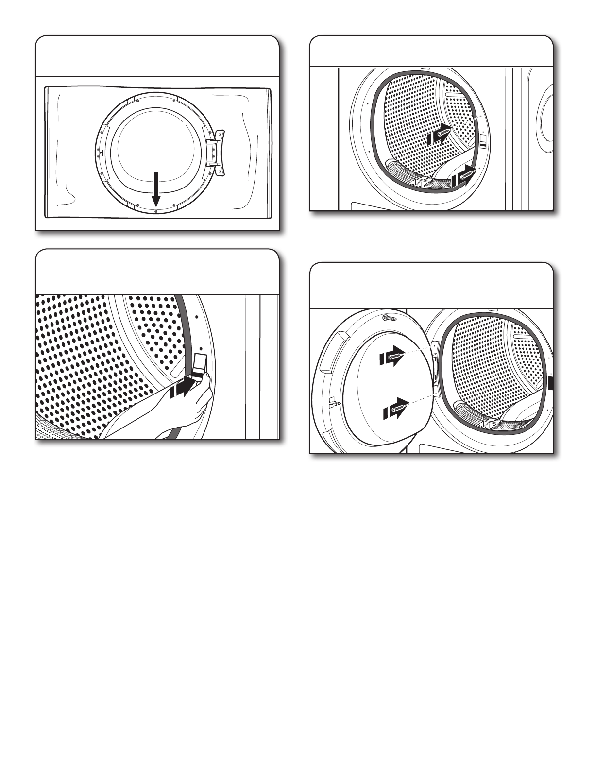
15. Flip over door so door glass
is on bottom
16. Replace chrome trim ring
29
17. Flip over door again so glass
faces up
18. Install door lock on right side
of door opening
19. Fasten door lock screws
20.
Fasten door to left side of door
opening
Press the door lock completely into the hole and move it
slightly downwards until the small knob of the door lock
latches.
Fasten the two trim screws located above and below the door
lock, to the right of the door opening.
Fasten the two screws to the door hinge.
30
TROUBLESHOOTING
If you experience Possible Causes Solution
Dryer Operation
Dryer will not run Door not closed completely. Make sure the dryer door is closed completely.
Start/Pause button not touched
firmly.
Touch the Start/Pause button firmly.
Bottom filter not in place. Place filter back in dryer and make sure the handle is properly
seated. The bottom filter indicator will light up if not properly
seated.
Household fuse is blown or circuit
breaker has tripped.
There may be 2 household fuses or circuit breakers for the dryer.
Check that both fuses are intact and tight, or that both circuit
breakers have not tripped. Replace the fuses or reset the circuit
breaker. If the problem continues, call an electrician.
Incorrect power supply.
Electric dryers require 240-volt power supply. Check with
a qualified electrician.
Wrong type of fuse. Use a time-delay fuse.
Unusual Noise
Thumping noise Dryer hasn’t been used in a while.
This is due to temporary flat spots on the drum rollers.
The thumping sound will diminish after a few minutes.
Rattling or vibrating noise A small object caught between the
edges of dryer drum.
Check the front and rear edges of the drum for small objects.
Clean out pockets before laundering.
Dryer isn’t properly leveled.
The dryer may vibrate if not properly installed. See “Installation
Instructions.” All four dryer feet should be in firm contact with
the floor.
Clothing is balled up in dryer.
When balled up, the load will bounce, causing the dryer
to vibrate. Separate the load items and restart the dryer.
Loud humming or
increased noise during
cycle
Load is packed tightly.
Reduce load size to recommended load size in “Program/Cycle
Guide.” Run the dryer for 5–10 minutes.
Dryer Results
Clothes are not drying
satisfactorily or drying
times are too long
Lint screen is clogged with lint. Clean lint screen before each load.
Bottom filter and screen is clogged
with lint.
Clean bottom filter after every 5th cycle.
The dryer is not level.
Clothes not contacting the moisture sensors during Automatic
Cycles. See “Level Dryer” in “Installation Instructions.”
The load is too large and heavy
to dry quickly.
Separate the load to tumble freely.
Fabric softener sheets are
blocking the grille.
The air outlet grille is just inside the door. Check that it is not
blocked by a fabric softener sheet.
Use only one fabric softener sheet, and use it only once.
The dryer is located in a room with
temperature below 45ºF (7ºC).
Proper operation of dryer cycles requires temperatures above
45ºF (7ºC).
The dryer is located in a closet.
Closet doors must have ventilation openings at the top and
bottom of the door. The front of the dryer requires a minimum
of 1" (25 mm) of airspace, and, for most installations, the rear
of the dryer requires 5" (127 mm). See “Installation Instructions.”
First try the solutions suggested here or visit our website at www.whirlpool.com/product_help –
In Canada www.whirlpool.ca for assistance and to possibly avoid a service call.

31
TROUBLESHOOTING
If you experience Possible Causes Solution
Dryer Results (cont.)
There may be some
water in the bottom filter
or on floor
The dryer is not level.
Floor needs to have a slope less than 1" (25 mm). See “Level
Dryer” in “Installation Instructions.”
Bottom filter is not properly seated. Make sure filter is placed in the housing cabinet correctly.
See “Cleaning the Bottom Filter.”
Drain hose is longer than what was
provided. Verify water container and
hose connections.
Drain hose can be installed no higher than 36" (91 cm)
from bottom of the dryer. See “Drain System” in “Installation
Instructions.”
Cycle time is too short The load may not be contacting the
sensor strips on Automatic Cycles.
Level the dryer. See “Installation Instructions.” All four dryer feet
should be in firm contact with the floor.
The Automatic Cycle is ending early. Change the dryness level setting on Automatic Cycles.
Increasing or decreasing the dryness level will change the
amount of drying time in a cycle. If loads are consistently ending
too early, also see “Adapting the dryer to water conductivity.”
Lint on load Lint screen is clogged with lint. Clean lint screen before each load.
Stains on load Improper use of fabric softener. Add dryer fabric softener sheets at the beginning of the cycle.
Fabric softener sheets added to a partially dried load can
stain your garments. Do not use fabric softener sheets with
steam cycles.
Stains on drum Loose dyes in clothes. Drum stains are caused by dyes in clothing (usually blue jeans).
These will not transfer to other clothing.
Loads are wrinkled The load was not removed from dryer
at the end of the cycle.
Refer to garment care label instructions. Dry-clean-only
garments are not recommended.
The dryer was tightly packed. Dry smaller loads that can tumble freely. Results may also vary
depending on fabric type.
Odors Recent painting, staining, or
varnishing in the area where your
dryer is located.
Ventilate the area. When the odors or fumes are gone from the
area, rewash and dry the clothing.
Odors are left in garments after
wearing.
Rewash and dry the clothing.
Load too hot
Load removed before cool-down
portion of cycle complete.
Allow the dryer to complete the cool-down portion of the cycle
before removing the load.
Stains or lint buildup
on wall behind dryer
Dryer too close to wall.
Move dryer away from wall and make sure you have proper
ventilation.
First try the solutions suggested here or visit our website at www.whirlpool.com/product_help –
In Canada www.whirlpool.ca for assistance and to possibly avoid a service call.
32
TROUBLESHOOTING
If you experience Possible Causes Solution
Dryer Displays Code Message or LED Symbol Lights Up
Water tank is filled with water. Empty water tank; make sure to insert it properly afterwards.
Water tank is not correctly
positioned.
Push in the water tank to make sure that it is correctly inserted
in the tank compartment.
Bottom filter is blocked by lint. Clean the bottom filter; make sure to insert it properly afterwards.
Bottom filter is not correctly
positioned.
Push in the bottom filter and move the release levers into
a vertical position to make sure the filter is correctly inserted
in the filter compartment. Close the flap.
Door filter is blocked by lint. Remove and clean the door filter; afterwards, make sure to insert
it properly in the filter compartment.
Door filter is not correctly positioned. Check position of the door filter; make sure that it is properly
inserted in the filter compartment.
F01 to F04 A component has failed. Touch and hold the Power button for at least 3 seconds while
dryer is on.
F05 to F09 A component has failed. Turn off and unplug the dryer. Immediately open the door and
take out the laundry so that the heat can dissipate. Make sure
that the ambient temperature ranges between 41°F (5°C) and
95°F (35°C). After about one hour, plug in the dryer, load the
laundry, and start the program/cycle again. If the failure persists,
call for service.
F10 to F24 A component has failed. Turn off and unplug the dryer. After about half an hour, plug
in the dryer and start the program/cycle again. If the failure
persists, call for service.
First try the solutions suggested here or visit our website at www.whirlpool.com/product_help –
In Canada www.whirlpool.ca for assistance and to possibly avoid a service call.

33
Notes

34
Notes
35
WHIRLPOOL
®
LAUNDRY
LIMITED WARRANTY
ATTACH YOUR RECEIPT HERE. PROOF OF PURCHASE IS
REQUIRED TO OBTAIN WARRANTY SERVICE.
Please have the following information available when you call the
Customer eXperience Center:
■
Name, address, and telephone number
■
Model number and serial number
■
A clear, detailed description of the problem
■
Proof of purchase including dealer or retailer name and address
DISCLAIMER OF IMPLIED WARRANTIES
IMPLIED WARRANTIES, INCLUDING ANY IMPLIED WARRANTY OF MERCHANTABILITY OR IMPLIED WARRANTY OF FITNESS FOR
A PARTICULAR PURPOSE, ARE LIMITED TO ONE YEAR OR THE SHORTEST PERIOD ALLOWED BY LAW. Some states and provinces
do not allow limitations on the duration of implied warranties of merchantability or tness, so this limitation may not apply to you. This
warranty gives you specic legal rights, and you also may have other rights that vary from state to state or province to province.
LIMITATION OF REMEDIES; EXCLUSION OF INCIDENTAL AND CONSEQUENTIAL DAMAGES
YOUR SOLE AND EXCLUSIVE REMEDY UNDER THIS LIMITED WARRANTY SHALL BE PRODUCT REPAIR AS PROVIDED HEREIN.
WHIRLPOOL SHALL NOT BE LIABLE FOR INCIDENTAL OR CONSEQUENTIAL DAMAGES. Some states and provinces do not allow
the exclusion or limitation of incidental or consequential damages, so these limitations and exclusions may not apply to you. This
warranty gives you specic legal rights, and you also may have other rights that vary from state to state or province to province.
DISCLAIMER OF REPRESENTATIONS OUTSIDE OF WARRANTY
Whirlpool makes no representations about the quality, durability, or need for service or repair of this major appliance other than the
representations contained in this Warranty. If you want a longer or more comprehensive warranty than the limited warranty that comes
with this major appliance, you should ask Whirlpool or your retailer about buying an extended warranty.
11/14
IF YOU NEED SERVICE:
1. Before contacting us to arrange service, please determine whether your product requires repair.
Some questions can be addressed without service. Please take a few minutes to review the
Troubleshooting or Problem Solver section of the Use and Care Guide, scan the QR code on
the right to access additional resources, or visit https://www.whirlpool.com/product_help.
2. All warranty service is provided exclusively by our authorized Whirlpool Service Providers.
In the U.S. and Canada, direct all requests for warranty service to:
Whirlpool Customer eXperience Center
In the U.S.A. call 1-800-253-1301. In Canada call 1-800-807-6777.
If outside the 50 United States and Canada, contact your authorized Whirlpool dealer to determine if another warranty applies.
https://www.whirlpool.com/product_help
ONE YEAR LIMITED WARRANTY
WHAT IS COVERED
WHAT IS NOT COVERED
1. Commercial, non-residential, multiple-family use, or use inconsistent with published user,
operator, or installation instructions.
2. In-home instruction on how to use your product.
3. Service to correct improper product maintenance or installation, installation not in
accordance with electrical or plumbing codes, or correction of household electrical or
plumbing (i.e. house wiring, fuses, or water inlet hoses).
4. Consumable parts (i.e. light bulbs, batteries, air or water filters, preservation solutions,
etc.).
5.
Defects or damage caused by the use of non-genuine Whirlpool parts or accessories.
6. Conversion of your product from natural gas or L.P. gas or reversal of appliance doors.
7. Damage from accident, misuse, abuse, fire, floods, acts of God, or use with products not
approved by Whirlpool.
8. Repairs to parts or systems to correct product damage or defects caused by
unauthorized service, alteration, or modification of the appliance.
9. Cosmetic damage including scratches, dents, chips, and other damage to appliance
finishes unless such damage results from defects in materials and workmanship and is
reported to Whirlpool within 30 days.
10. Discoloration, rust, or oxidation of surfaces resulting from caustic or corrosive
environments, including but not limited to, high salt concentrations, high moisture or
humidity, or exposure to chemicals.
11. Pick-up or delivery. This product is intended for in-home repair.
12. Travel or transportation expenses for service in remote locations where an authorized
Whirlpool servicer is not available.
13. Removal or reinstallation of inaccessible appliances or built-in fixtures (i.e. trim,
decorative panels, flooring, cabinetry, islands, countertops, drywall, etc.) that interfere
with servicing, removal, or replacement of the product.
14. Service or parts for appliances with original model/serial numbers removed, altered, or
not easily determined.
The cost of repair or replacement under these excluded circumstances shall be
borne by the customer.
For one year from the date of purchase,
when this major appliance is installed,
operated, and maintained according
to instructions attached to or furnished
with the product, Whirlpool Corporation
or Whirlpool Canada LP (hereafter
“Whirlpool”) will pay for Factory
Specified Replacement Parts and repair
labor to correct defects in materials or
workmanship that existed when this major
appliance was purchased, or at its sole
discretion replace the product. In the event
of product replacement, your appliance
will be warranted by the remaining term of
the original unit’s warranty period.
YOUR SOLE AND EXCLUSIVE REMEDY
UNDER THIS LIMITED WARRANTY
SHALL BE PRODUCT REPAIR AS
PROVIDED HEREIN. Service must be
provided by a Whirlpool designated
service company. This limited warranty
is valid only in the United States or
Canada and applies only when the major
appliance is used in the country in which
it was purchased. This limited warranty
is effective from the date of original
consumer purchase. Proof of original
purchase date is required to obtain service
under this limited warranty.
Assistance or Service
Before calling for assistance or service, please check “Troubleshooting” or visit www.whirlpool.com/help.
It may save you the cost of a service call. If you still need help, follow the instructions below.
When calling, please know the purchase date and the complete model and serial number of your appliance.
This information will help us to better respond to your request.
Whirlpool Brand Appliances
Customer eXperience Center
553 Benson Road
Benton Harbor, MI 49022-2692
1-866-698-2538
Whirlpool Brand Appliances
Customer eXperience Centre
Unit 200-6750 Century Ave
Mississauga, Ontario L5N 0B7
1-800-688-2002
You can write with any questions or concerns at:
Our consultants provide assistance with
Please include a daytime phone number in your correspondence.
If you need replacement parts or to order accessories
We recommend that you use only FSP
®
Factory Specified Parts.
These parts will fit right and work right because they are made with the same precision
used to build every new WHIRLPOOL
®
appliance.
To locate FSP
®
replacement parts or accessories go to www.whirlpoolpartsonline.com.
Questions? Call us toll free at 1-866-698-2538 or in Canada call 1-800-688-2002.
In the U.S.A.
■ Features and specifications on our full line of appliances.
■ Installation information.
■ Specialized customer assistance (Spanish speaking,
hearing impaired, limited vision, etc.).
In the U.S.A. and Canada
■ Use and maintenance procedures.
■ Accessory and repair parts sales.
■ Referrals to local dealers, repair parts distributors,
and service companies. Whirlpool designated service
technicians are trained to fulfill the product warranty and
provide after-warranty service, anywhere in the United
States and Canada.
Assistance ou Service
Avant de faire un appel pour obtenir de l’assistance ou un entretient, vérifier la section “Dépannage” ou consulter
www.whirlpool.com/help. Cette vérification peut vous faire économiser le coût d’une visite de réparation.
Si vous avez encore besoin d’aide, suivre les instructions ci-dessous.
Lors d’un appel, garder à portée de main la date d’achat et les numéros de modèle et de série de votre appareil.
Ces renseignements nous aideront à mieux répondre à votre demande.
Pour commander des pièces de rechange ou des accessoires
Pour commander des pièces de rechange, nous vous recommandons d’utiliser seulement
des pièces spécifiées par l’usine. Ces pièces conviendront et fonctionneront bien parce qu’elles sont fabriquées selon
les mêmes spécifications précises utilisées pour construire chaque nouvel appareil WHIRLPOOL
®
.
Pour trouver des pièces de rechange FSP
®
ou des accessoires, visiter le www.whirlpool.ca.
Des questions? Composer le numéro sans frais
1-800-688-2002.
Pour plus d’assistance
Vous pouvez nous soumettre toute question ou toute
problème en écrivant à l’adresse ci-dessous :
Whirlpool Brand Appliances
Centre pour l’eXpérience de la clientèle
Unit 200-6750 Century Ave
Mississauga, Ontario L5N 0B7
1-800-688-2002
Dans votre correspondance, veuillez indiquer un numéro
de téléphone où nous pouvons vous joindre dans la journée.
Nos consultants fournissent
l’assistance pour :
■ Procédés d’utilisation et d’entretien.
■ Vente d’accessoires et de pièces de rechange.
■ Références aux concessionnaires, compagnies de service
de réparation et distributeurs de pièces de rechange
locaux. Les techniciens de service désignés par Whirlpool
sont formés pour remplir la garantie des produits et fournir
un service après la garantie, partout au Canada.
W10858718B
W10858720B - SP 10/16
®
/
TM
© 2016 Whirlpool. All rights reserved. Used under license in Canada.
®
/
TM
© 2016 Whirlpool. Tous droits réservés. Emploi sous licence au Canada.