
Operator's Manual
CRRFr MRN
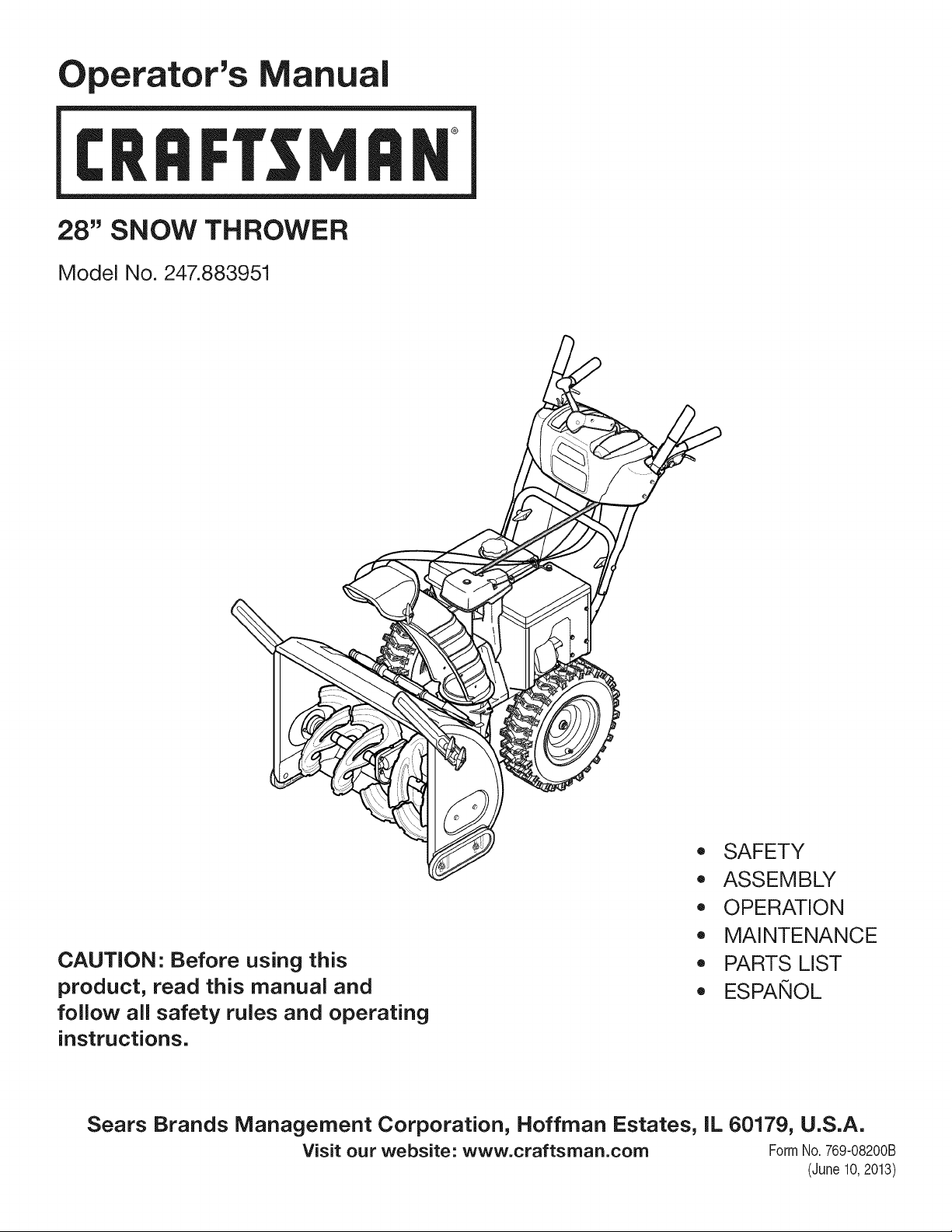
28" SNOW THROWER
Model No. 247.883951
CAUTION" Before using this
product, read this manual and
follow all safety rules and operating
instructions.
,, SAFETY
o ASSEMBLY
OPERATION
MAINTENANCE
PARTS LIST
o ESPANOL
Sears Brands Management Corporation, Hoffman Estates, IL 60179, U.S.A.
Visit our website: www.craftsman.com FormI/o 769-08200B
(June 10,2013)
WarrantyStatement.............................. Page2
SafeOperationPractices...................... Pages3-6
Assembly.................................... Pages8-13
Operation.................................. Pages14-17
Service&Maintenance....................... Pages18-23
Off-SeasonStorage............................. Page24
Troubleshooting............................... Page26
PartsList................................... Pages28-44
RepairProtectionAgreement.................... Page47
Espa_ol........................................ Page48
CRAFTSMANTWOYEARFULLWARRANTY
FORTWOYEARSfromthedateof purchase,this productiswarrantedagainstanydefectsin materialorworkmanship.Defectiveproductwill receivefree
repairorfreereplacementif repairisunavailable.
ADDITIONALLIFETIMELIMITEDWARRANTYon UPPERand LOWERCHUTE
FORASLONGASITISUSEDbytheoriginalownerafterthesecondyearfromthedateofpurchase,theupperandlowerchuteofthissnowthrowerare
warrantedagainstanydefectsinmaterialorworkmanshipasverifiedbyaSearsauthorizedserviceprovider.Withproofofpurchase,youwill receiveanew
chutefreeofcharge.Youareresponsiblefor thelaborcostofinstallationandanycostincurredto verifythedefect.
Forwarrantycoveragedetailsto obtainrepairorreplacement,visitthewebsite:www.craftsman.com
ThiswarrantycoversONLYdefectsinmaterialandworkmanship.WarrantycoveragedoesNOTinclude:
• Expendableitemsthatcanwearoutfrom normalusewithin thewarrantyperiod,includingbutnotlimitedto augers,augerpaddles,drift cutters,skid
shoes,shaveplate,shearpins,sparkplug,air cleaner,belts,andoilfilter.
• Standardmaintenanceservicing,oilchanges,ortune-ups.
• Tirereplacementorrepaircausedbypuncturesfromoutsideobjects,suchasnails,thorns,stumps,orglass.
• Tireor wheelreplacementorrepairresultingfromnormalwear,accident,or improperoperationormaintenance.
• Repairsnecessarybecauseofoperatorabuse,includingbutnot limitedto damagecausedbyover-speedingtheengine,orfrom impactingobjectsthat
bendtheframe,augershaft,etc.
• Repairsnecessarybecauseofoperatornegligence,includingbutnot limitedto,electricalandmechanicaldamagecausedbyimproperstorage,failureto
usethepropergradeandamountofengineoil,orfailureto maintaintheequipmentaccordingto theinstructionscontainedinthe operator'smanual.
• Engine(fuelsystem)cleaningorrepairscausedbyfueldeterminedto be contaminatedor oxidized(stale).Ingeneral,fuelshouldbeusedwithin 30days
ofitspurchasedate.
• Normaldeteriorationandwearoftheexteriorfinishes,or productlabelreplacement.
Thiswarrantyisvoidif thisproductiseverusedwhileprovidingcommercialservicesorif rentedto anotherperson.
Thiswarrantygivesyouspecificlegalrights,andyoumayalsohaveotherrightswhichvaryfrom stateto state.
SearsBrandsManagementCorporation,NoffmanEstates,IL60179
Engine Oil: 5W-30
Fuel: Unleaded Gasoline
Engine: MTD
Model Number
Serial Number
Date of Purchase
Record the model number, serial number,
and date of purchase above.
© Sears Brands, LLC 2
Thissymbolpointsout importantsafety instructionswhich, if not
followed, couldendangerthe personalsafetyand/or property of
yourself and others.Readandfollow all instructions inthis manual
beforeattempting to operatethis machine.Failureto complywith these
instructionsmay resultinpersonalinjury.Whenyou seethis symbol, HEED
ITSWARNING!
CALIFORNIA PROPOSITION 65
EngineExhaust,someof its constituents,and certainvehiclecomponents
containor emit chemicalsknownto Stateof Californiato causecancerand
birth defectsorother reproductiveharm.
Thismachinewasbuilt to beoperatedaccordingto thesafeoperation
practicesinthis manual.Aswith anytype of powerequipment,
carelessnessorerror onthe part of the operatorcanresultinseriousinjury.
Thismachineiscapableof amputating fingers, hands,toesandfeet and
throwingdebris. Failureto observethefollowing safety instructionscould
resultin seriousinjuryor death.
Your Responsibility--Restrict the useof this powermachineto
personswho read, understandandfollow the warningsand instructionsin
this manualandon the machine.
SAVETHESEINSTRUCTIONS!
TRAINING
Read,understand,andfollowall instructionsonthemachineandinthe
manual(s)beforeattemptingto assembleandoperate.Failureto dosocan
resultinseriousinjury totheoperatorand/orbystanders.Keepthis manual
inasafeplaceforfutureandregularreferenceandfororderingreplacement
parts.
Befamiliarwith allcontrolsandtheir properoperation.Knowhowto stop
themachineanddisengagethemquickly.
Neverallowchildrenunder14yearsof ageto operatethis machine.Children
14andovershouldreadandunderstandtheinstructionsandsafeoperation
practicesinthis manualandonthemachineandbetrainedandsupervised
byanadult.
Neverallowadultsto operatethismachinewithout properinstruction.
Thrownobjectscancauseseriouspersonalinjury.Planyoursnow-throwing
patternto avoiddischargeof materialtowardroads,bystandersandthelike.
Keepbystanders,petsandchildrenat least75feetfromthe machinewhile it
isin operation.Stopmachineif anyoneentersthe area.
Exercisecautionto avoidslippingorfalling,especiallywhenoperatingin
reverse.
PREPARATION
Thoroughlyinspecttheareawheretheequipmentisto beused.Removeall
doormats,newspapers,sleds,boards,wiresandotherforeignobjects,which
couldbetrippedoverorthrownbytheauger/impeller.
Alwayswearsafetyglassesor eyeshieldsduringoperationandwhile
performinganadjustmentor repairto protectyoureyes.Thrownobjects
whichricochetcancauseseriousinjuryto theeyes.
Donotoperatewithout wearingadequatewinteroutergarments.Donot
wearjewelry,longscarvesorotherlooseclothing,whichcouldbecome
entangledinmovingparts.Wearfootwearwhichwill improvefootingon
slipperysurfaces.
Usea groundedthree-wireextensioncordandreceptacleforall machines
with electricstartengines.
Disengageall controlleversbeforestartingtheengine.
Adjustcollectorhousingheightto cleargravelor crushedrocksurfaces.
Neverattemptto makeanyadjustmentswhileengineisrunning,except
wherespecificallyrecommendedintheoperator'smanual.
Letengineandmachineadjustto outdoortemperaturebeforestartingto
clearsnow.
Safe Handling of Gasoline:
Toavoid personalinjuryor property damageuseextremecareinhandling
gasoline.Gasolineisextremely flammable andthe vaporsareexplosive.
Seriouspersonalinjurycanoccurwhengasolineis spilledon yourselfor your
clotheswhichcanignite. Washyour skinandchangeclothesimmediately.
Useonlyanapprovedgasolinecontainer.
Neverfill containersinsidea vehicleor ona truckortrailerbedwitha plastic
liner.Alwaysplacecontainersonthe groundawayfrom yourvehiclebefore
filling.
Whenpractical,removegas-poweredequipmentfrom the truckor
trailer andrefuelit ontheground.Ifthisis notpossible,thenrefuelsuch
equipmenton atrailerwith aportablecontainer,ratherthanfrom agasoline
dispensernozzle.
Keepthenozzleincontactwith therimofthe fuel tankorcontaineropening
at alltimesuntil fuelingiscomplete.Donot usea nozzlelock-opendevice.
Extinguishall cigarettes,cigars,pipesandothersourcesof ignition.
Neverfuel machineindoors.
Neverremovegascapor addfuel whiletheengineishotorrunning.Allow
engineto coolat leasttwo minutesbeforerefueling.
Neveroverfill fueltank.Filltankto nomorethan1/2inchbelowbottomof
filler neckto allowspacefor fuelexpansion.
Replacegasolinecapandtightensecurely.
Ifgasolineisspilled,wipeit offthe engineandequipment.Moveunitto
anotherarea.Wait.5minutesbeforestartingtheengine.
Toreducefirehazards,keepmachinefreeofgrass,leaves,orotherdebris
build-up.Cleanupoilorfuelspillageandremoveanyfuelsoakeddebris.
Neverstorethemachineorfuelcontainerinsidewherethereisanopen
flame,sparkorpilotlightasonawaterheater,spaceheater,furnace,clothes
dryerorothergasappliances.
OPERATION
Donotputhandsorfeetnearrotatingparts,intheauger/impellerhousing
orchuteassembly.Contactwith therotatingpartscanamputatehandsand
feet.
Theauger/impellercontrolleverisasafetydevice.Neverbypassits
operation.Doingsomakesthe machineunsafeandmaycausepersonal
injury.
Thecontrolleversmustoperateeasilyin bothdirectionsandautomatically
returnto thedisengagedpositionwhenreleased.
Neveroperatewith amissingordamagedchuteassembly.Keepall safety
devicesin placeandworking.
Neverrunanengineindoorsor inapoorlyventilatedarea.Engineexhaust
containscarbonmonoxide,anodorlessanddeadlygas.
Donotoperatemachinewhileundertheinfluenceof alcoholordrugs.
Mufflerandenginebecomehotandcancauseaburn.Donot touch.Keep
childrenaway.
Exerciseextremecautionwhenoperatingonorcrossinggravelsurfaces.Stay
alertforhiddenhazardsortraffic.
Exercisecautionwhenchangingdirectionandwhileoperatingonslopes.Do
notoperateon steepslopes.
Planyoursnow-throwingpatternto avoiddischargetowardswindows,
walls,carsetc.Thus,avoidingpossiblepropertydamageorpersonalinjury
causedbyaricochet.
Neverdirectdischargeat children,bystandersandpetsor allowanyonein
front of themachine.
Donotoverloadmachinecapacitybyattemptingto clearsnowat toofastof
arate.
Neveroperatethismachinewithoutgoodvisibilityorlight. Alwaysbesureof
yourfootingandkeepafirm holdon the handles.Walk,neverrun.
Disengagepowerto the auger/impellerwhentransportingornot in use.
Neveroperatemachineat hightransportspeedsonslipperysurfaces.Look
downandbehindandusecarewhenbackingup.
If themachineshouldstartto vibrateabnormally,stoptheengine,
disconnectthesparkplugwire andgrounditagainsttheengine.Inspect
thoroughlyfordamage.Repairanydamagebeforestartingandoperating.
Disengageall controlleversandstopenginebeforeyouleavetheoperating
position(behindthehandles).Waituntil theauger/impellercomesto
acompletestopbeforeuncloggingthe chuteassembly,makingany
adjustments,orinspections.
Neverputyourhandin thedischargeor collectoropenings.Donotunclog
chuteassemblywhileengineis running.Shutoff engineandremainbehind
handlesuntil allmovingpartshavestoppedbeforeunclogging.
Useonlyattachmentsandaccessoriesapprovedbythe manufacturer(e.g.
wheelweights,tirechains,cabsetc.).
Whenstartingengine,pull cordslowlyuntil resistanceisfelt, thenpull
rapidly.Rapidretractionofstartercord(kickback)will pullhandandarm
towardenginefasterthanyoucanletgo. Brokenbones,fractures,bruisesor
sprainscouldresult.
Ifsituationsoccurwhicharenot coveredinthismanual,usecareandgood
judgment.
CLEARING A CLOGGED DISCHARGE CHUTE
Handcontactwith therotatingimpellerinsidethedischargechuteisthe most
commoncauseof injuryassociatedwith snowthrowers.Neveruseyourhandto
cleanout thedischargechute.
Toclearthe chute:
a. SHUTTHEENGINEOFF!
b. Wait 10secondsto besurethe impellerbladeshavestopped
rotating.
c. Alwaysuseaclean-outtool,notyourhands.
MAINTENANCE & STORAGE
Nevertamperwith safetydevices.Checktheirproperoperationregularly.
Referto themaintenanceandadjustmentsectionsof thismanual.
Beforecleaning,repairing,orinspectingmachinedisengageall control
leversandstoptheengine.Waituntil theauger/impellercometo acomplete
stop.Disconnectthesparkplugwire andgroundagainsttheengineto
preventunintendedstarting.
Checkboltsandscrewsforpropertightnessat frequentintervalsto keepthe
machineinsafeworkingcondition.Also,visuallyinspectmachineforany
damage.
Donotchangetheenginegovernorsettingor over-speedtheengine.The
governorcontrolsthemaximumsafeoperatingspeedof theengine.
Snowthrowershaveplatesandskidshoesaresubjectto wearanddamage.
Foryoursafetyprotection,frequentlycheckall componentsandreplace
with originalequipmentmanufacturer's(OEM)partsonlyaslistedinthe
Partspagesofthisoperator'smanual.Useof partswhichdonot meetthe
originalequipmentspecificationsmayleadto improperperformanceand
compromisesafety!
Checkcontrolleversperiodicallyto verifytheyengageanddisengage
properlyandadjust,if necessary.Referto theadjustmentsectioninthis
operator'smanualfor instructions.
Maintainorreplacesafetyandinstructionlabels,asnecessary.
Observeproperdisposallawsandregulationsforgas,oil,etc.to protectthe
environment.
Priorto storing,runmachineafewminutesto clearsnowfrommachineand
preventfreezeupof auger/impeller.
Neverstorethemachineor fuelcontainerinsidewherethereisanopen
flame,sparkorpilot light suchasa waterheater,furnace,clothesdryeretc.
Alwaysreferto theoperator'smanualforproperinstructionsonoff-season
storage.
4
Checkfuelline,tank,cap,andfittingsfrequentlyfor cracksor leaks.Replace
if necessary.
Donotcrankenginewith sparkplugremoved.
Accordingto theConsumerProductsSafetyCommission(CPSC)andthe
U.S.EnvironmentalProtectionAgency(EPA),thisproducthasan Average
Useful Life of seven(7)years,or 60 hoursofoperation.Attheendof
theAverage Useful Life havethemachineinspectedannuallybyan
authorizedservicedealerto ensurethat all mechanicalandsafetysystems
areworkingproperlyandnotwornexcessively.Failureto dosocanresultin
accidents,injuriesor death.
DO NOT MODIFY ENGINE
Toavoidseriousinjuryor death,do notmodifyengineinanyway. Tampering
with the governorsetting canlead to arunawayengineandcauseit to
operateat unsafespeeds.Nevertamper with factory setting of engine
governor.
NOTICE REGARDING EMiSSiONS
Engineswhich are certifiedto complywith Californiaandfederal EPA
emissionregulationsfor SORE(SmallOff RoadEquipment)arecertified
to operateon regularunleadedgasoline,and mayincludethe following
emissioncontrolsystems:EngineModification (EM),OxidizingCatalyst(0C),
SecondaryAir injection(SAI)andThreeWayCatalyst(TWC)if soequipped.
SPARK ARRESTOR
e
Thismachineisequippedwith an internalcombustionengine andshould
not be usedon or near any unimprovedforest-covered,brushcoveredor
grass-coveredland unlessthe engine'sexhaustsystemis equippedwith a
sparkarrestormeeting applicable localorstate laws (if any).
Ira sparkarrestoris used,it shouldbe maintainedin effective working order
bythe operator.In theState of Californiathe aboveisrequired bylaw (Section
4442of the CaliforniaPublicResourcesCode).Otherstates mayhavesimilar
laws.Federallaws apply on federal lands.
Asparkarrestorfor the muffler is availablethroughyour nearestSearsParts
andRepairServiceCenter.
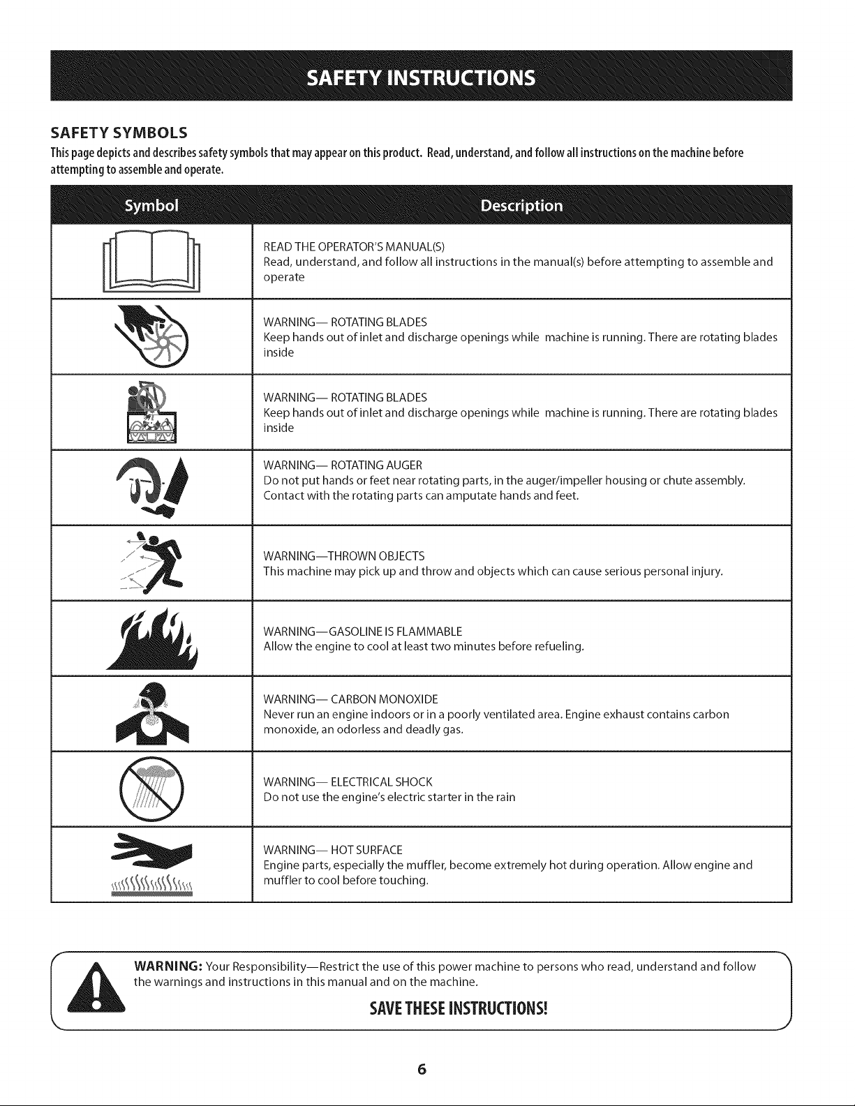
SAFETY SYMBOLS
Thispage depicts and describes safety symbols that may appear on this product. Read, understand, and follow all instructions on the machine before
attempting to assemble and operate.
READ THE OPERATOR'S MANUAL(S)
Read, understand, and follow all instructions in the manual(s) before attempting to assemble and
operate
WARNING-- ROTATING BLADES
Keep hands out of inlet and discharge openings while machine is running. There are rotating blades
inside
WARNING-- ROTATING BLADES
Keep hands out of inlet and discharge openings while machine is running. There are rotating blades
inside
WARNING-- ROTATING AUGER
Do not put hands or feet near rotating parts, in the auger/impeller housing or chute assembly.
Contact with the rotating parts can amputate hands and feet.
WARNING--THROWN OBJECTS
This machine may pick up and throw and objects which can cause serious personal injury.
WARNING--GASOLINE IS FLAMMABLE
Allow the engine to cool at least two minutes before refueling.
WARNING-- CARBON MONOXIDE
Never run an engine indoors or in a poorly ventilated area. Engine exhaust contains carbon
monoxide, an odorless and deadly gas.
WARNING-- ELECTRICAL SHOCK
Do not use the engine's electric starter in the rain
WARNING-- HOT SURFACE
Engine parts, especially the muffler, become extremely hot during operation. Allow engine and
muffler to cool before touching.
WARNING: Your Responsibility--Restrict the use of this power machine to persons who read, understand and follow
the warnings and instructions in this manual and on the machine.
SAVETHESEiNSTRUCTIONS!
6

This page left intentionallyblank.
7
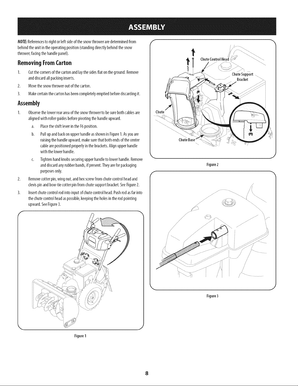
NOTE:Referencesto rightor left sideofthe snowthroweraredeterminedfrom
behindtheunit in theoperatingposition(standingdirectlybehindthesnow
thrower,facingthehandlepanel).
Removing FromCarton
1. Cutthecornersof thecartonandlaythe sidesflat on theground.Remove
anddiscardall packinginserts.
2. Movethe snowthrowerout of thecarton.
3. Makecertainthe cartonhasbeencompletelyemptiedbeforediscardingit.
Assembly
Observethelowerrearareaof thesnowthrowerto besurebothcablesare
alignedwith rollerguidesbeforepivotingthe handleupward.
a. Placetheshift [everintheF6position.
b. Pullup andbackonupperhandleasshownin Figure1.Asyouare
raisingthe handleupward,makesurethat bothendsof thecenter
cablearepositionedproperlyinthe brackets.Alignupperhandle
withthe lowerhandle.
c. Tightenhandknobssecuringupperhandleto lowerhandle.Remove
anddiscardanyrubberbands,if present.Theyarefor packaging
purposesonly.
Removecotterpin, wingnut,andhexscrewfrom chutecontrolheadand
clevispinandbow-tiecotterpinfromchutesupportbracket.SeeFigure2.
Insertchutecontrolrodinto inputof chutecontrolhead.Pushrodasfarinto
thechutecontrolheadaspossible,keepingtheholesin therodpointing
upward.SeeFigure3.
f
t
Figure2
f
/ .....
j
Rgure3
Figure 1
J
8

4. Placechuteontochutebaseandensurechutecontrolrodispositionedunder
handlepanel.Installhexbolt previouslyremovedbutdonotsecurewith
wingnut at thistime.SeeFigure4.
5. Squeezethetriggeronthehandlepaneljoystickandrotatethechuteby
handto faceforward.Theholesinthechutecontrolinputwill befacingup.
SeeFigure5.
NOTE:Thechutewill not rotatewithoutsqueezingthetriggeronthe joystick.
6. Rotatethejoysticktotheoneo'clockpositionsothesliverindicatorarrowon
theinputshaftbelowthe controlpanelpointsupward.SeeFigure6.
NOTE:Thejoystickwill be angledslightlyto theright.SeeFigure5& Figure6.
f
Figure4
TopView
Figure 5
//f "_
FrontView
Joystick
\
Figure6
9
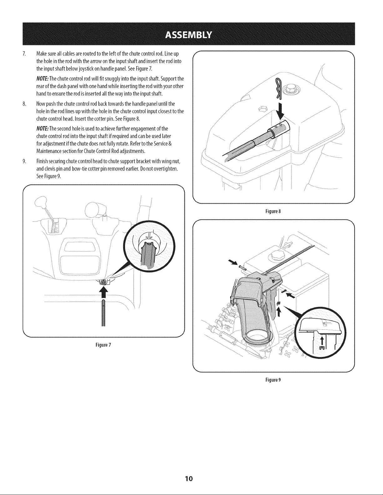
7. Makesureall cablesareroutedto theleft of thechutecontrolrod.Lineup
theholeintherodwith thearrowonthe inputshaftandinserttherodinto
theinputshaftbelowjoystickon handlepanel.SeeFigure7.
NOTE:Thechutecontrolrodwill fit snugglyintotheinputshaft.Supportthe
rearofthedashpanelwith onehandwhileinsertingtherodwith yourother
handto ensurethe rodisinsertedall the wayintothe inputshaft.
8. Nowpushthechutecontrolrodbacktowardsthe handlepaneluntil the
holeintherodlinesup with the holeinthechutecontrolinputclosestto the
chutecontrolhead.Insertthecotter pin.SeeFigure8.
NOTE:Thesecondholeisusedto achievefurther engagementof the
chutecontrolrodinto theinputshaftif requiredandcanbeusedlater
foradjustmentif thechutedoesnotfully rotate.Referto theService&
Maintenancesectionfor ChuteControlRodadjustments.
9. Finishsecuringchutecontrolheadto chutesupportbracketwith wing nut,
andclevispinandbow-tiecotterpinremovedearlier.Donotovertighten.
SeeFigure9.
f
Figure7
f
/ /
Figure8
f
\
Figure9
10
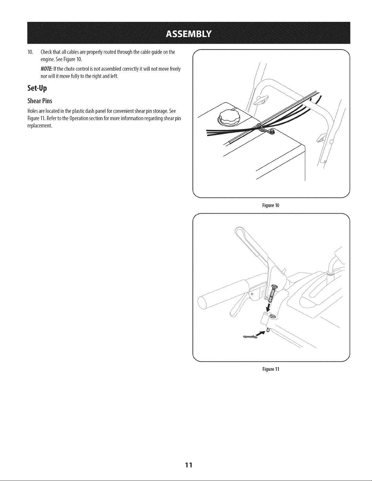
Checkthatallcablesareproperlyroutedthroughthe cableguideonthe
engine.SeeFigure10.
NOTE:Ifthechutecontrolisnotassembledcorrectlyit will notmovefreely
norwill it movefully to the rightandleft.
Set-Up
ShearPins
Holesarelocatedin theplasticdashpanelfor convenientshearpinstorage.See
Figure11.Referto theOperationsectionfor moreinformationregardingshearpin
replacement.
/
; S
Figure10
J
f
Figure11
J
11
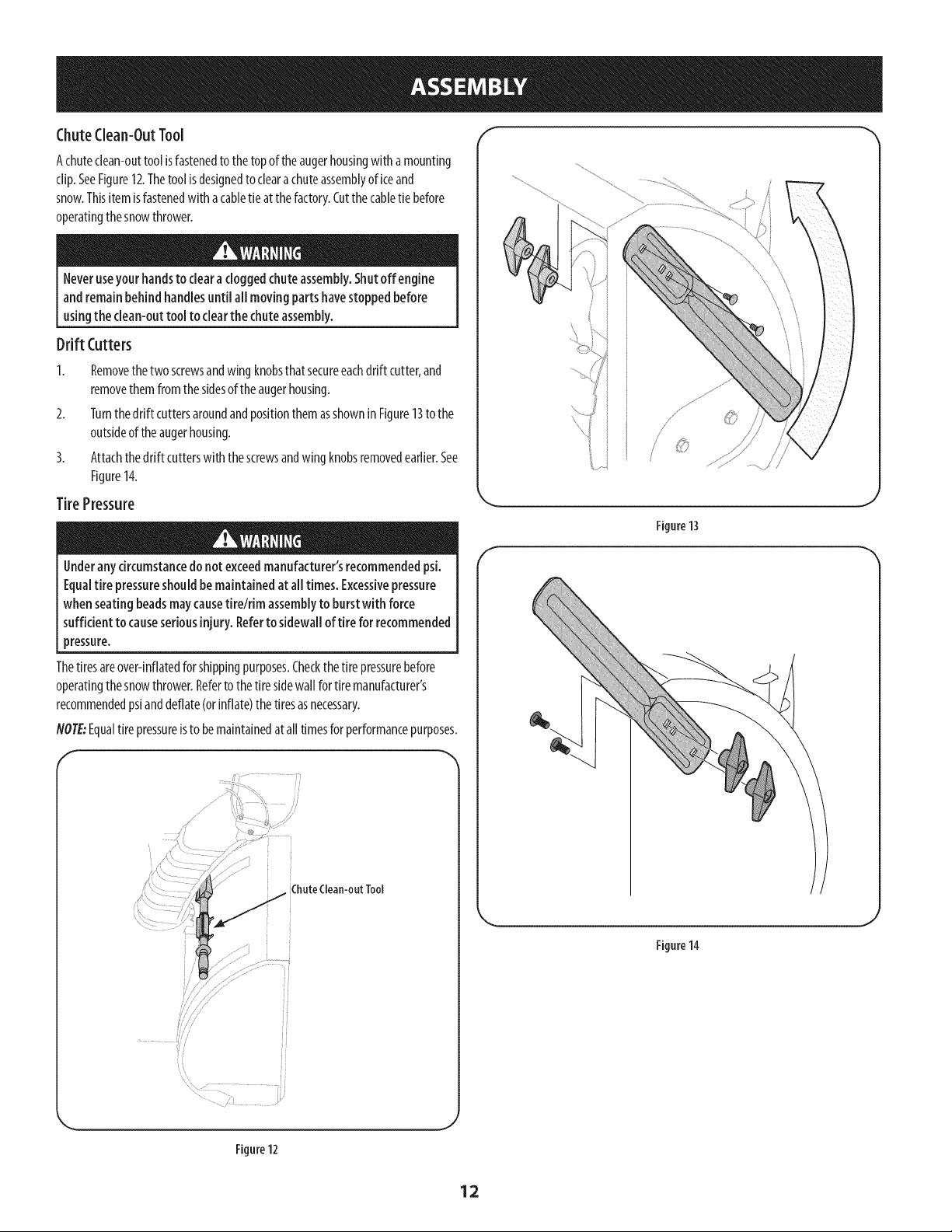
ChuteClean-OutTool _
Achuteclean-outtool isfastenedto thetop oftheaugerhousingwith amounting
clip.SeeFigure12.Thetoolisdesignedto clearachuteassemblyof iceand
snow.Thisitemisfastenedwith acabletie at thefactory.Cutthe cabletie before
operatingthesnowthrower.
Neveruseyour handsto clearaclogged chuteassembly.Shutoff engine
and remainbehind handlesuntil all movingpartshavestoppedbefore
usingthe clean-outtool to clearthe chuteassembly.
Drift Cutters
1. Removethe two screwsandwingknobsthatsecureeachdrift cutter,and
removethemfromthe sidesof theaugerhousing.
2. Turnthe drift cuttersaroundandpositionthemasshownin Figure13to the
outsideof theaugerhousing.
3. Attachthedrift cutterswith thescrewsandwingknobsremovedearlier.See
Figure14.
TirePressure
Underanycircumstancedo notexceedmanufacturer'srecommendedpsi.
Equaltire pressureshouldbe maintained at all times.Excessivepressure
when seatingbeadsmaycausetirelrim assemblyto burstwith force
sufficient to causeseriousinjury. Referto sidewall of tire for recommended
pressure.
Thetiresareover-inflatedforshippingpurposes.Checkthetire pressurebefore
operatingthesnowthrower.Refertothetire sidewall for tire manufacturer's
recommendedpsianddeflate(orinflate)thetiresasnecessary.
NOTE:Equaltire pressureisto bemaintainedat alltimesforperformancepurposes.
ChuteClean-outTool
Figure13
J
Figure14
Figure 12
J
12
Adjustments f
Skid Shoes
Thesnowthrowerskidshoesareadjustedupwardat thefactoryforshipping
purposes.Adjustthemdownward,if desired,priorto operatingthesnowthrower.
it is notrecommendedthat you operatethis snowthrower on gravelas
it caneasilypickup andthrowloosegravel,causingpersonalinjuryor
damageto the snow thrower andsurroundingproperty.
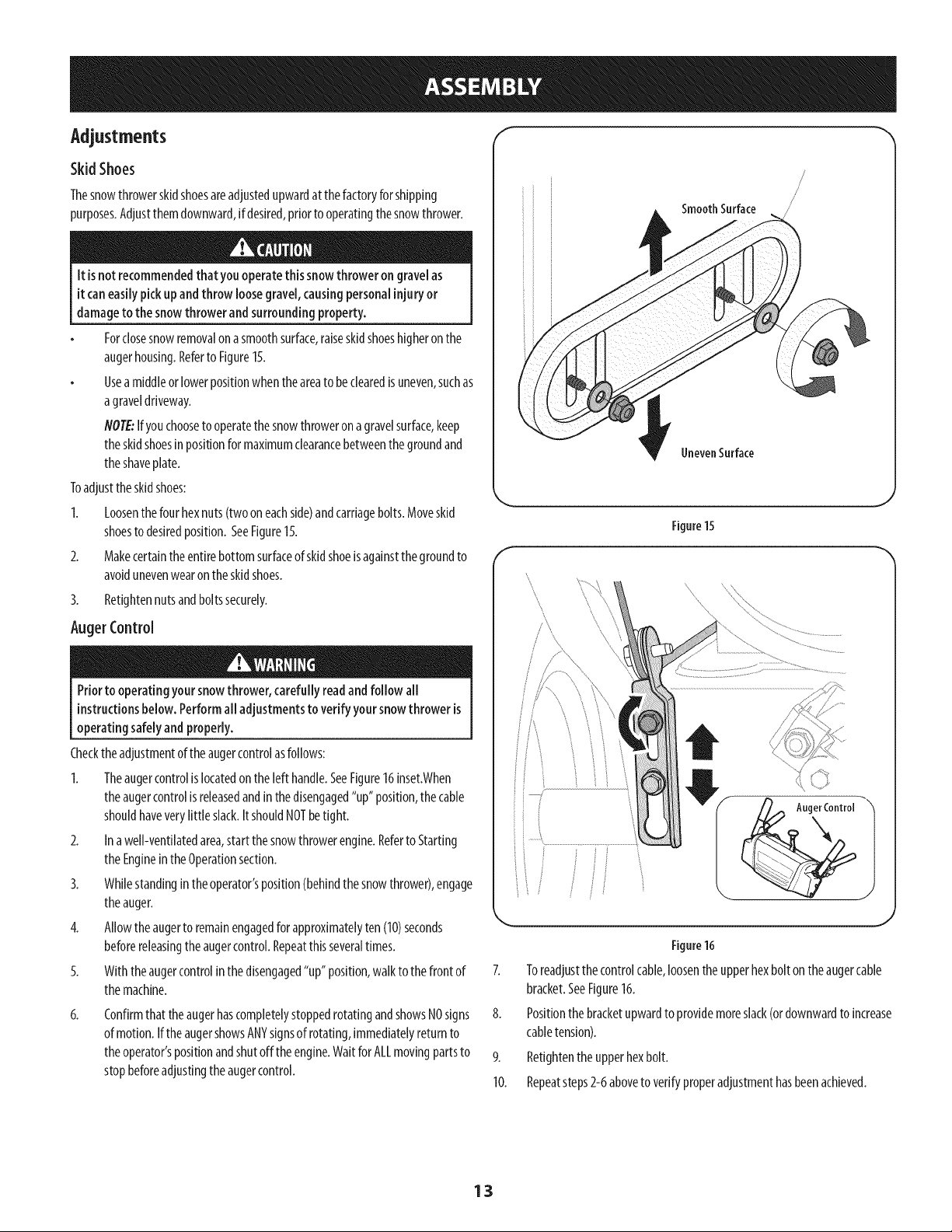
Forclosesnowremovalon asmoothsurface,raiseskidshoeshigheronthe
augerhousing.Referto Figure15.
Usea middleorlowerpositionwhentheareato beclearedis uneven,suchas
agraveldriveway.
NOTE:Ifyouchooseto operatethesnowthrowerona gravelsurface,keep
theskidshoesinpositionformaximumclearancebetweenthe groundand
theshaveplate.
Toadjustthe skidshoes:
1. Loosenthefour hexnuts(two oneachside)andcarriagebolts.Moveskid
shoesto desiredposition. SeeFigure15.
2. Makecertainthe entirebottomsurfaceof skidshoeisagainstthegroundto
avoidunevenwearon the skidshoes.
3. Retightennutsandboltssecurely.
AugerControl
Priorto operatingyoursnowthrower,carefully readand follow all
instructionsbelow. Performall adjustmentsto verify yoursnowthroweris
operating safelyand properly.
Checktheadjustmentoftheaugercontrolasfollows:
1. Theaugercontrolislocatedon the left handle.SeeFigure16inset.When
theaugercontrolisreleasedandinthedisengaged"up"position,thecable
shouldhaveverylittle slack.ItshouldNOTbetight.
2. Ina well-ventilatedarea,start thesnowthrowerengine.Referto Starting
theEnginein theOperationsection.
3. Whilestandingintheoperator'sposition(behindthesnowthrower),engage
theauger.
4. Allowtheaugerto remainengagedfor approximatelyten (10)seconds
beforereleasingtheaugercontrol.Repeatthisseveraltimes.
5. With theaugercontrolin thedisengaged"up" position,walkto the front of
themachine.
6.
Confirmthat the augerhascompletelystoppedrotatingandshowsNOsigns
of motion.IftheaugershowsANYsignsof rotating,immediatelyreturnto
theoperator'spositionandshut off theengine.WaitforALLmovingpartsto
stopbeforeadjustingthe augercontrol.
Smooth Surface
UnevenSurface
Figure15
J
..................................................... ............................
f /,
/
/_ Auger Control--
J
\ J
Figure16
7. Toreadjustthecontrolcable,loosenthe upperhexbolton the augercable
bracket.SeeFigure16.
8. Positionthe bracketupwardto providemoreslack(ordownwardto increase
cabletension).
9. Retightenthe upperhexbolt.
10. Repeatsteps2-6aboveto verifyproperadjustmenthasbeenachieved.
13
Drive Control
Headlight
Gas C_
Shift Lever
_ Four-Way Chute ControP (Joystick)
Auger Control
Wheel Steering Control
Chute Assembly
\
Drift Cutter
Auger
Hous_
\
Clean Out
Tool
\
Augers
Skid Shoe
Choke
Control Throttle
Control
Oil Drain
Recoil Starter
Oil Fill
Handle
Electric Starter Outlet
Figure17
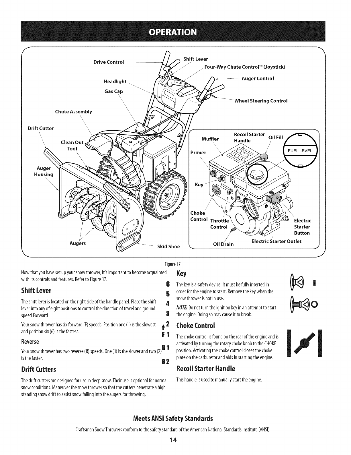
Nowthatyouhavesetupyoursnowthrower,it's importantto becomeacquainted
with itscontrolsandfeatures.Referto Figure17.
Shift [ever
Theshift leverislocatedonthe right sideof the handlepanel.Placethe shift
leverintoanyof eightpositionsto controlthedirectionof travelandground
speed.Forward
Yoursnowthrowerhassixforward(F)speeds.Positionone(1)isthe slowest
andpositionsix(6)isthefastest.
Reverse
Yoursnowthrowerhastwo reverse(R)speeds.One(1)istheslowerandtwo (2)R 1
isthefaster. R 2
Drift Cutters
,ey6 Thekeyisasafetydevice.It mustbefully insertedin Ii
5 orderfor theenginetostart. Removethe keywhenthe
snowthrowerisnotin use. (_ O
4 NOTE:Donot turn theignitionkeyinan attemptto start
3 theengine.Doingsomaycauseit to break.
t 2 ChokeControl
activated by turning the rotary choke knob to the CHOKE
position.Activatingthe choke controlclosesthe choke
plate on the carburetorand aids instarting the engine.
RecoUStarterHandle
Thedrift cuttersaredesignedfor useindeepsnow.Theiruseisoptionalfor normal
snowconditions.Maneuverthe snowthrowersothatthecutterspenetratea high
standingsnowdrift to assistsnowfallinginto the augersforthrowing.
Thishandleisusedto manuallystarttheengine.
MeetsANSiSafetyStandards
CraftsmanSnowThrowersconformto thesafetystandardof theAmericanNationalStandardsInstitute(ANSI).
14
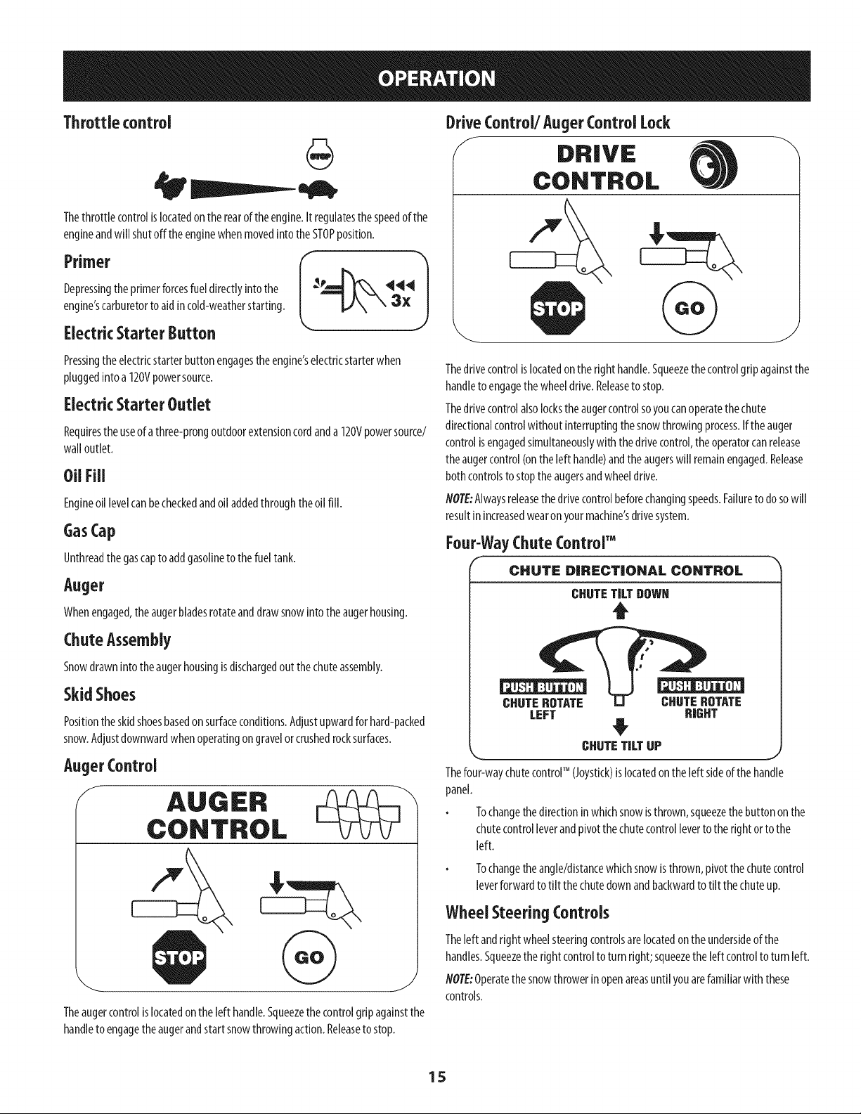
Throttlecontrol
Thethrottlecontrolislocatedonthe rearofthe engine.It regulatesthespeedofthe
engineandwill shutoffthe enginewhen movedinto the STOPposition.
Primer
Depressingthe primerforcesfueldirectlyintothe
engine'scarburetorto aid incold-weatherstarting.
Electric Starter Button
Pressingthe electricstarterbuttonengagestheengine'selectricstarterwhen
pluggedinto a 120Vpowersource.
Electric Starter Outlet
Requirestheuseof athree-prongoutdoorextensioncordanda 120Vpowersource/
wall outlet.
OilFill
Engineoil levelcanbecheckedandoil addedthroughtheoil fill.
GasCap
Unthreadthe gascapto addgasolinetothefuel tank.
Auger
Whenengaged,theaugerbladesrotateanddrawsnowintotheaugerhousing.
ChuteAssembly
Snowdrawninto theaugerhousingisdischargedoutthe chuteassembly.
Skid Shoes
Positiontheskidshoesbasedonsurfaceconditions.Adjustupwardforhard-packed
snow.Adjustdownwardwhenoperatingongravelorcrushedrocksurfaces.
AugerControl
f
Theaugercontrolislocatedon the left handle.Squeezethecontrolgripagainstthe
handleto engagethe augerandstartsnowthrowingaction.Releaseto stop.
DriveControl/Auger Control Lock
/ DRIVE
CONTROL
Thedrivecontrolislocatedontheright handle.Squeezethecontrolgripagainstthe
handleto engagethe wheeldrive.Releaseto stop.
Thedrivecontrolalsolockstheaugercontrolsoyoucanoperatethechute
directionalcontrolwithoutinterruptingthesnowthrowingprocess.Ifthe auger
controlisengagedsimultaneouslywiththe drivecontrol,theoperatorcanrelease
theaugercontrol(ontheleft handle)andtheaugerswill remainengaged.Release
bothcontrolsto stoptheaugersandwheeldrive.
flOTE:Alwaysreleasethedrivecontrolbeforechangingspeeds.Failureto dosowill
resultinincreasedwearon yourmachine'sdrivesystem.
Four-WayChute Contror M
CHUTe: DIRECTIONAL CONTROL
CHUTETILT DOWN
t
CHUTEROTATE CHUTEROTATE
LEFT RIGHT
CHUTETILT UP
_r n_
Thefour-waychutecontrolTM (Joystick)is locatedontheleft sideofthe handle
panel.
Tochangethedirectioninwhichsnowisthrown,squeezethe buttonon the
chutecontrolleverandpivotthechutecontrolleverto therightorto the
left.
Tochangetheangle/distancewhichsnowisthrown,pivotthechutecontrol
leverforwardto tilt thechutedownandbackwardto tilt thechuteup.
Wheel Steering Controls
Theleft andright wheelsteeringcontrolsarelocatedon the undersideof the
handles.Squeezethe rightcontrolto turn right;squeezethe left controltoturn left.
NOTE:Operatethesnowthrowerinopenareasuntil youarefamiliarwith these
controls.
15
Clean-OutTool
Neveruseyour handsto clearacloggedchuteassembly.Shutoff engine
and remainbehindhandlesuntil all movingparts havestoppedbefore
usingthe clean-outtool to clearthe chuteassembly.
Thechutedean-outtool isconvenientlyfastenedto therearoftheaugerhousing
with amountingclip.Shouldsnowandicebecomelodgedin thechuteassembly
duringoperation,proceedasfollowsto safelycleanthe chuteassemblyandchute
opening:
1. ReleaseboththeAugerControlandthe DriveControl.
2. Stopthe enginebyremovingthe ignitionkey.
3. Removethe clean-outtool fromtheclipwhichsecuresit to the rearof the
augerhousing.
4. Usetheshovel-shapedendof theclean-outtool to dislodgeandscoopany
snowandicewhichhasformedinandnearthe chuteassembly.
5. Refastentheclean-outtool to the mountingdip on therearof theauger
housing,reinserttheignitionkeyandstartthesnowthrower'sengine.
6. Whilestandingintheoperator'sposition(behindthe snowthrower),engage
theaugercontrolforafewsecondstoclearanyremainingsnowandicefrom
thechuteassembly.
BeforeStarting Engine
Read,understand,andfollow all instructionsandwarnings onthe
machineandinthis manualbeforeoperating.
Oil
Theunit wasshippedwith oilintheengine.Checkoil levelbeforeeachoperationto
ensureadequateoilin theengine.
flO?E:Besureto checkthe engineonalevelsurfacewith theenginestopped.
1. Removethe oil filler cap/dipstickandwipethe dipstickclean.
2. Insertthecap/dipstickinto the oil filler neck,butdo NOTscrewit in.
3. Removethe oil filler cap/dipstick.Ifthe levelislow,slowlyaddoil(5W-30,
with aminimumclassificationof SF/SG)until oillevelregistersbetweenhigh
(H)andlow (L).
4.
flOTE:Donotoverfill.Overfillingwith oil mayresultin enginesmoking,hard
startingorsparkplugfouling.
Replaceandtighten cap/dipstickfirmlybeforestartingengine.
Gasoline
Useautomotivegasoline(unleadedorlowleadedto minimizecombustionchamber
deposits)with a minimumof87 octane.Gasolinewith up to 10%ethanolor15%
MTBE(MethylTertiaryButylEther)canbeused.Neveruseanoil/gasolinemixture
ordirty gasoline.Avoidgetting dirt, dust,orwaterinthe fuel tank.DONOTuseE85
gasoline.
Refuelin awell-ventilatedareawith theenginestopped.Donotsmokeor
allowflamesor sparksin theareawherethe engineisrefueledorwhere
gasolineisstored.
Donotoverfill the fueltank.Afterrefueling,makesurethetankcapisclosed
properlyandsecurely.
Becarefulnot to spillfuelwhen refueling.Spilledfuel orfuel vapormay
ignite.If anyfuelisspilled,makesuretheareaisdry beforestartingthe
engine.
Avoidrepeatedor prolongedcontactwith skinorbreathingofvapor.
Useextreme carewhenhandling gasoline.Gasolineis extremely
flammable andthe vaporsareexplosive.Neverfuel the machineindoorsor
while the engineishotor running. Extinguishcigarettes,cigars,pipesand
othersourcesof ignition.
1.
2.
Cleanaroundfuelfill beforeremovingcapto fuel.
Afuel levelindicatoris locatedinthe fuel tank.SeeFigure17inset.Be
carefulnotto overfill.Filltankuntil fuel reachesthefuellevelindicatorto
allowspacefor fuelexpansion.
Starting The Engine
Alwayskeephandsandfeet clearof moving parts.Donot usea pressurized
starting fluid. Vaporsareflammable.
flOTE:Allowtheengineto warmupfor afewminutesafter starting.Theenginewill
notdevelopfull poweruntil it reachesoperatingtemperatures.
1. Makecertainboththe augercontrolanddrivecontrolarein thedisengaged
(released)position.
2. Insertkeyinto slot.Makesureit snapsinto place.Donot attemptto turn the
key.
NOTE:Theenginecannotstartwithoutthekeyfully insertedinto the
ignitionswitch.
ElectricStarter
Theelectric starter isequippedwith a groundedthree-wire power plug,
andisdesignedto operateon 120voltAChouseholdcurrent.It must be
usedwith a properly groundedthree-prong receptacleat all timesto avoid
the possibilityof electrk shock.Followall instructionscarefully priorto
operatingthe electricstarter. DONOTuseelectric starter inthe rain.
Determinethatyourhome'swring isathree-wiregroundedsystem.Aska licensed
electricianif youarenotcertain.
Ifyouhavea groundedthree-prongreceptacle,proceedasfollows.If youdonot
havethe properhousewiring, DONOTusethe electricstarterunderanyconditions.
1. Pluganextensioncordintothe outletlocatedon the engine'ssurface.Plug
theotherendofextensioncordintoathree-prong120-volt,grounded,AC
outlet inawell-ventilatedarea.
Theextensioncordcan beany length, but must be ratedfor 15ampsat
125volts,groundedand ratedfor outdoor use.
16
2. Movethrottle controlto FAST(rabbit)_Jl__ position.
3 MovechoketotheCHOKEI,'I pos t on co,deng nestart),fengine s
warm,placechokein RUNposition.
4. Pushprimerthree(3)times,makingsureto coverventholeinprimerbulb
whenpushing.Ifengineiswarm,pushprimeronlyonce.Alwayscovervent
holewhenpushing.Coolweathermayrequirepriming to berepeated.
5. Pushstarterbuttonto startengine.Oncetheenginestarts,immediately
releasestarterbutton.Electricstarterisequippedwith thermaloverload
protection;systemwill temporarilyshut-downto allowstarterto coolif
electricstarterbecomesoverloaded.
6.
Asthe enginewarms,slowlyrotatethe chokecontrolto RUNposition.Ifthe
enginefalters,restartengineandrunwith chokeat half-chokepositionfor a
shortperiodof time,andthenslowlyrotatethe chokeinto RUNposition.
Afterengineisrunning,disconnectpowercordfrom electricstarter.When
disconnecting,alwaysunplugtheendat the wall outletbeforeunplugging
theoppositeendfrom theengine.
RecoilStarter
Donot pull the starter handlewhilethe enginerunning.
1. Movethrottle controlto FAST(rabbit)_ _j position.
2. Movechoketo theCHOKEI,.'1position(coldenginestart).If engineis
warm,placechokein RUNposition.
3. Pushprimerthree(3)times,makingsureto coverventholewhenpushing.
If engineiswarm,pushprimeronlyonce.Alwayscoverventholewhen
pushing.Coolweathermayrequireprimingto be repeated.
4. Pullgentlyonthe starterhandleuntil it beginsto resist,then pullquickly
andforcefullyto overcomethe compression.Donotreleasethe handleand
allowit to snapback.ReturnropeSLOWLYto originalposition.If required,
repeatthisstep.
5. Asthe enginewarms,slowlyrotatethe chokecontrolto RUNposition.Ifthe
enginefalters,restartengineandrunwith chokeat half-chokepositionfor a
shortperiodof time,andthenslowlyrotatethe chokeinto RUNposition.
Toavoid unsupervisedengineoperation, neverleavethe machine
unattendedwith theengine running. Turnthe engineoff after useand
removekey.
Stopping TheEngine
Afteryouhavefinishedsnow-throwing,runenginefor afewminutesbefore
stoppingto helpdryoffany moistureon theengine.
1. Movethrottle controlto OFFposition.
2. Removethe key.Removingthe keywill reducethepossibilityof
unauthorizedstartingof the enginewhileequipmentisnot inuse.Keepthe
keyina safeplace.Theenginecannotstartwithout thekey.
3. Wipeanymoistureawayfrom thecontrolson theengine.
ToEngageDrive
1. With thethrottlecontrolinthe Fast(rabbit)_ _1 position,moveshift lever
into oneof thesixforward(F)positionsor two reverse(R)positions.Selecta
speedappropriatefor thesnowconditionsanda paceyou'recomfortable
with.
NOTE:Whenselectinga DriveSpeed,usetheslowerspeedsuntilyouare
comfortableandfamiliarwith theoperationof thesnowthrower.
2. Squeezethe drivecontrolagainstthehandleandthesnowthrowerwill
move.Releaseit anddrivemotionwill stop.
NOTE:NEVERrepositiontheshift lever(changespeedsor directionof travel)
without first releasingthedrivecontrolandbringingthesnowthrowerto a
completestop.Doingsowill resultin prematurewearto the snowthrower'sdrive
system.
ToEngageAuger
Toengagetheaugerandstartthrowingsnow,squeezethe augercontrol
againstthe left handle.Releaseto stopthe auger.
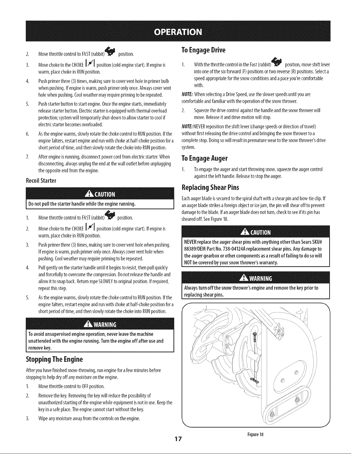
ReplacingShearPins
Eachaugerbladeissecuredto thespiralshaftwith ashearpinandbow-tieclip.If
anaugerbladestrikesa foreignobjectoricejam, the pinwill shearoff to prevent
damageto theblade.Ifan augerbladedoesnot turn, checkto seeif itspinhas
shearedoff. SeeFigure18.
NEVERreplacethe augershearpinswith anything otherthan SearsSKU#
88389/0EMPart No.738-04124Areplacementshearpins.Any damageto
the augergearboxorother componentsasa result of failing to do sowill
NOTbe coveredbyyour snowthrower'swarranty.
Alwaysturn off the snowthrower'sengine and removethe keypriorto
replacingshearpins.
Figure18
17
MAINTENANCESCHEDULE
Beforeperformingany type of maintenance/service,disengageall controls
andstopthe engine.Wait until all moving partshavecometo a complete
stop. Disconnectsparkplug wire and groundit againstthe engine to
preventunintendedstarting.
EachUseand every 5hours
Ist 5hours
Annuallyor25hours
Annuallyor50hours
Annuallyor100hours
BeforeStorage
Followthe maintenanceschedulegivenbelow.Thischartdescribesservice
guidelinesonly.UsetheServiceLogcolumnto keeptrackofcompleted
maintenancetasks.TolocatethenearestSearsServiceCenteror to scheduleservice,
simplycontactSearsat 1-800-4-MY-HOME®.
1. Engineoil level
2. Looseor missinghardware
3. Unitandengine.
1. Engineoil
1. Sparkplug
2. Controllinkagesandpivots
3. Wheels
4. GearshaftandAugershaft
5. 4-WayChuteControlTM
1. Engineoil
1. Sparkplug
1. Fuelsystem
GENERALRECOMMENDATIONS
CheckingEngine Oil
Beforelubricating, repairing,or inspecting,disengageall controlsandstop
engine.Wait until all movingparts havecometo acompletestop.
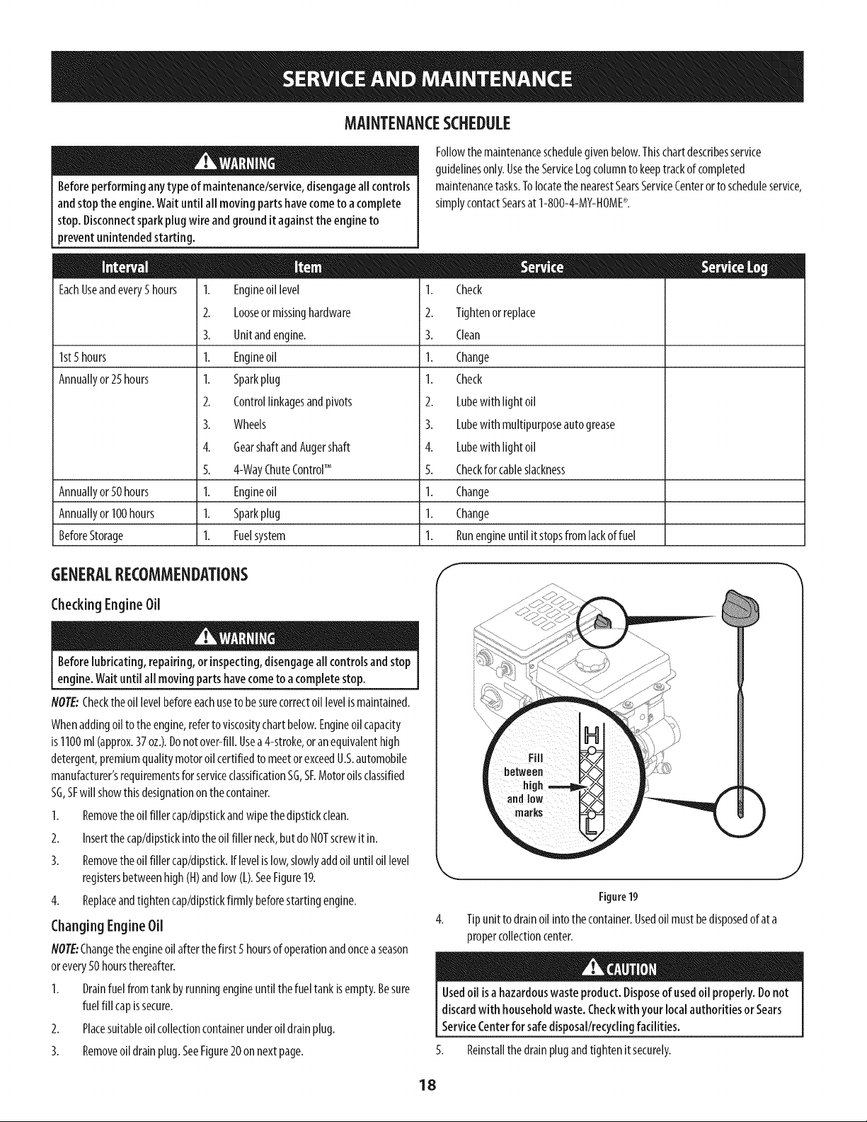
NOTE:Checkthe oil levelbeforeeachuseto besurecorrectoil levelismaintained.
Whenaddingoil to theengine,referto viscositychartbelow.Engineoil capacity
is1100ml(approx.37oz.).Donot over-fill.Usea4-stroke,or anequivalenthigh
detergent,premiumquality motoroil certifiedto meetor exceedU.S.automobile
manufacturer'srequirementsforserviceclassificationSG,SF.Motoroilsclassified
SG,SFwill showthisdesignationon thecontainer.
1. Removethe oil filler cap/dipstkkandwipethe dipstickclean.
2. Insertthecap/dipstickintotheoil filler neck,butdo NOTscrewit in.
3. Removethe oil filler cap/dipstick.Iflevelis low,slowlyaddoil until oil level
registersbetweenhigh(H)andlow (L).SeeFigure19.
4. Replaceandtighten cap/dipstickfirmlybeforestartingengine.
Changing EngineOil
NOTE:Changethe engineoil after thefirst 5 hoursof operationandoncea season
orevery50 hoursthereafter.
1. Drainfuel fromtankbyrunningengineuntil thefueltankisempty.Besure
fuelfill capissecure.
2. Placesuitableoil collectioncontainerunderoil drainplug.
1. Check
2. Tightenorreplace
3. Clean
1. Change
1. Check
2. Lubewith light oil
3. Lubewith multipurposeautogrease
4. Lubewith light oil
5. Checkfor cableslackness
1. Change
1. Change
1. Runengineuntil itstopsfrom lackoffuel
f
3. Removeoil drainplug.SeeFigure20 onnextpage.
Figure19
Tipunitto drainoil intothecontainer.Usedoil mustbedisposedof at a
propercollectioncenter.
Usedoil isa hazardouswaste product.Disposeof usedoil properly.Donot
discardwith householdwaste. Checkwithyour localauthorities or Sears
ServiceCenterfor safedisposal/recyclingfacilities.
5. Reinstallthedrainplugandtighten it securely.
J
18
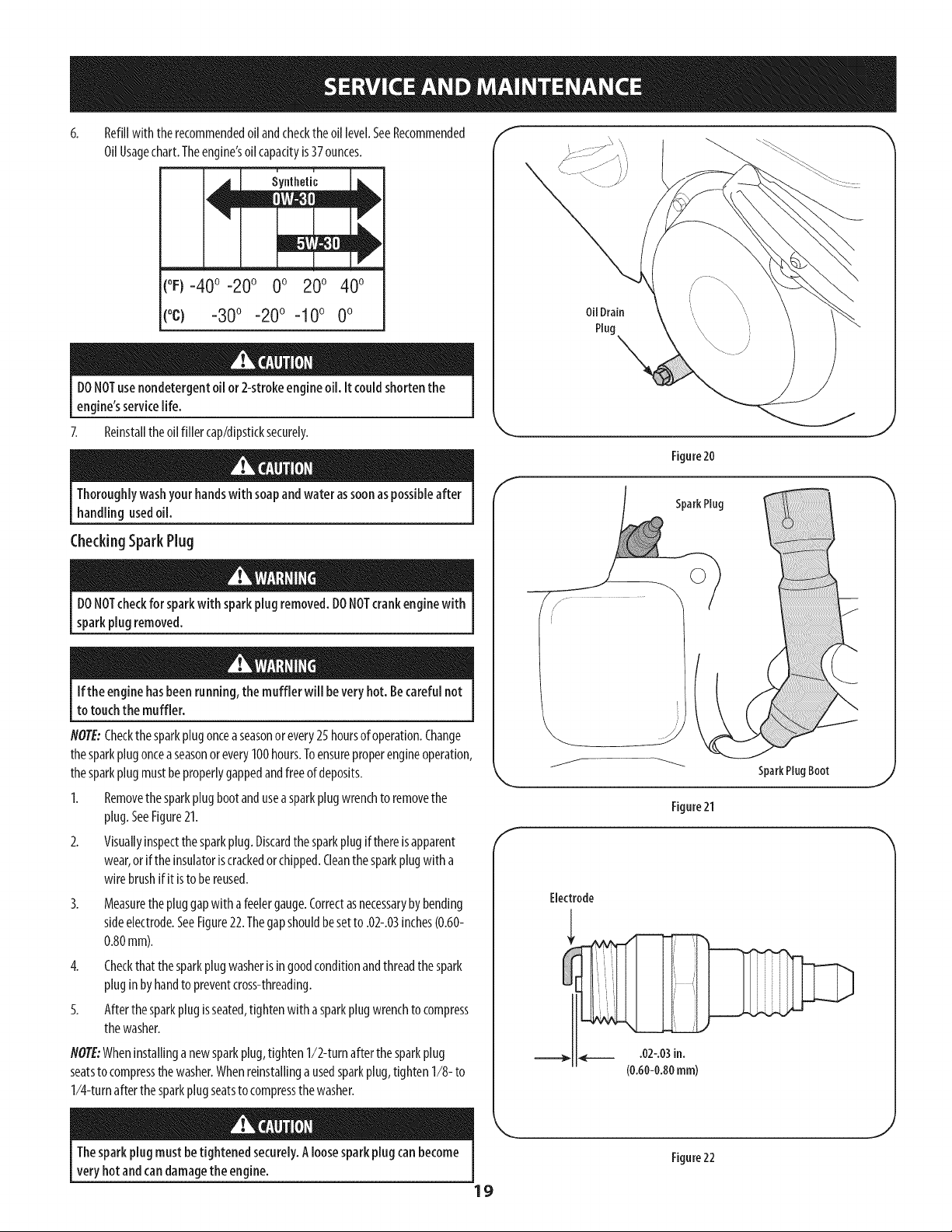
Refillwith therecommendedoil andchecktheoil level.SeeRecommended
OilUsagechart.Theengine'soilcapacityis37ounces.
(oF)-40o-20 o 0o 200 400
(oc) -30° -20° -10 ° 0°
DONOTuse nondetergentoil or 2-strokeengineoil. It couldshorten the
engine'sservicelife.
7. Reinstalltheoil filler cap/dipsticksecurely.
Thoroughlywashyourhandswith soapandwater assoonaspossibleafter
handling usedoil.
CheckingSparkPlug
DONOTcheckfor sparkwith sparkplug removed.DONOTcrankenginewith
sparkplug removed.
Ifthe engine hasbeenrunning,the muffler will bevery hot. Becarefulnot
to touchthe muffler.
NOTE:Checkthe sparkplugonceaseasonor every25 hoursof operation.Change
thesparkplugonceaseasonorevery100hours.Toensureproperengineoperation,
thesparkplugmustbeproperlygappedandfreeof deposits.
1. Removethe sparkplugbootandusea sparkplugwrenchto removethe
plug.SeeFigure21.
2. Visuallyinspectthesparkplug.Discardthesparkplugif thereisapparent
wear,or if theinsulatoriscrackedor chipped.Cleanthesparkplugwith a
wirebrushifit isto bereused.
3.
Measurethe pluggapwith afeelergauge.Correctasnecessarybybending
sideelectrode.SeeFigure22.Thegapshouldbesetto .02-.03inches(0.60-
0.80mm).
4. Checkthatthesparkplug washerisin goodconditionandthreadthespark
pluginbyhandto preventcross-threading.
5. Afterthesparkplugisseated,tightenwith asparkplugwrenchto compress
thewasher.
NOTE:Wheninstallinganewsparkplug,tighten1/2-turnafterthe sparkplug
seatsto compressthe washer.Whenreinstallinga usedsparkplug,tighten1/8- to
1/4-turnafter thesparkplugseatsto compressthewasher.
Oil Drain
Plug \
Figure20
E
SparkPlug
SparkPlugBoot
Figure21
Electrode
Thesparkplug mustbe tightened securely.Aloosesparkplugcan become
very hotandcan damagethe engine.
19
Figure22

Lubrication "I
GearShaft
Thegear(hex)shaftshouldbelubricatedat leastonceaseasonor after every25
hoursof operation.
I. Topreventspillage,removeall fuel fromtank byrunningengineuntil it
stops.
2. Carefullypivotthe snowthrowerupandforwardsothat it restsonthe auger
housing.
3. Removethe lowerframecoverfrom the undersideof thesnowthrowerby
removingtheself-tappingscrewswhichsecureit.
4. Applya lightcoatingof engineoil (or3-in-1oil) to the hexshaft.SeeFigure
23.
NOTE:Whenlubricatingthe hexshaft,becarefulnot to getanyoil onthe aluminum
driveplateorrubberfrictionwheel.Doingsowill hinderthe snowthrower'sdrive
system.Wipeoff anyexcessor spilledoil.
Wheels
Atleastonceaseason,removebothwheels.Cleanandcoattheaxleswith a
multipurposeautomotivegreasebeforereinstallingwheels.
AugerShaft
Atleastonceaseason,removetheshearpinson augershaft.Spraylubricantinside
shaft,andaroundthe spacersandflangebearingsfoundat eitherendof theshaft.
SeeFigure24.
ShavePlate and Skid Shoes
Theshaveplateandskidshoeson the bottomofthe snowthroweraresubjectto
wear.Theyshouldbecheckedperiodicallyandreplacedwhennecessary.
flOTE:Theskidshoeson thismachinehavetwo wearedges.Whenonesidewears
out,theycanberotated180° to usethe otheredge.
Toremoveskidshoes:
Removethetwocarriagebolts,washers,andhexflangenutsthatsecure
eachskidshoetothesnowthrower.
2. Reassemblenewskidshoeswith thefourcarriagebolts(two on eachside),
washers,andhexflangenuts.Referto Figure25.
Toremoveshaveplate:
1. Removethe carriageboltsandhexnutswhichattachit to thesnowthrower
housing.
2. Reassemblenewshaveplate,makingsureheadsof carriageboltsareto the
insideof housing.Tightensecurely.SeeFigure25.
f
Figure 23
J
f
Figure24
NOTE:Augersnot shownfor clarity.
Figure 25
20
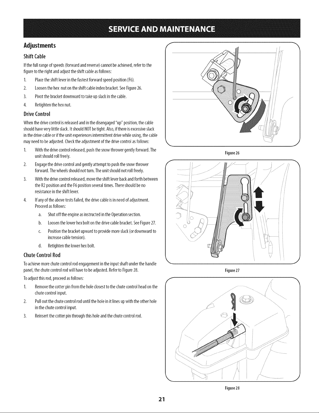
Adjustments
Shift Cable
If thefull rangeof speeds(forwardandreverse)cannotbeachieved,referto the
figureto thefight andadjusttheshift cableasfollows:
I. Placetheshift leverinthe fastestforwardspeedposition(F6).
2. Loosenthehex nutontheshift cableindexbracket.SeeFigure26.
3. Pivotthe bracketdownwardtotake upslackinthecable.
4. Retightenthe hexnut.
DriveControl
Whenthedrivecontrolis releasedandinthe disengaged"up" position,the cable
shouldhaveverylittle slack.ItshouldNOTbetight. Also,if thereisexcessiveslack
inthedrivecableor if theunit experiencesintermittentdrivewhileusing,the cable
mayneedto beadjusted.Checkthe adjustmentof thedrivecontrolasfollows:
I. With thedrivecontrolreleased,pushthesnowthrowergentlyforward.The
unit shouldroll freely.
2. Engagethedrivecontrolandgentlyattemptto pushthesnowthrower
forward.Thewheelsshouldnotturn. Theunitshouldnotroll freely.
3. With thedrivecontrolreleased,movetheshift leverbackandforth between
theR2positionandthe F6positionseveraltimes.Thereshouldbeno
resistancein theshift lever.
4. If anyof theabovetestsfailed,thedrivecableisinneedof adjustment.
Proceedasfollows:
a. Shutoff the engineasinstructedinthe Operationsection.
b. Loosenthelowerhexbolt onthedrivecablebracket.SeeFigure27.
c. Positionthebracketupwardto providemoreslack(ordownwardto
increasecabletension).
d. Retightenthe lowerhexbolt.
ChuteControlRod
Toachievemorechutecontrolrodengagementinthe inputshaftunderthe handle
panel,the chutecontrolrodwill haveto beadjusted.Referto Figure28.
Toadjustthisrod,proceedasfollows:
I. Removethe cotterpin fromtheholeclosestto thechutecontrolheadon the
chutecontrolinput.
2. Pullout thechutecontrolroduntilthe holeinit linesupwith theotherhole
inthechutecontrolinput.
3. Relnsertthe cotterpinthroughthisholeandthe chutecontrolrod.
f
Figure26
Figure27
/
i /
/
/
/
/
/
/
figure28
21
AugerControl
Referto theAssemblysectionforinstructionson adjustingtheaugercontrolcable.
Skid Shoes
Referto theAssemblysectionforinstructionson adjustingtheskidshoes.
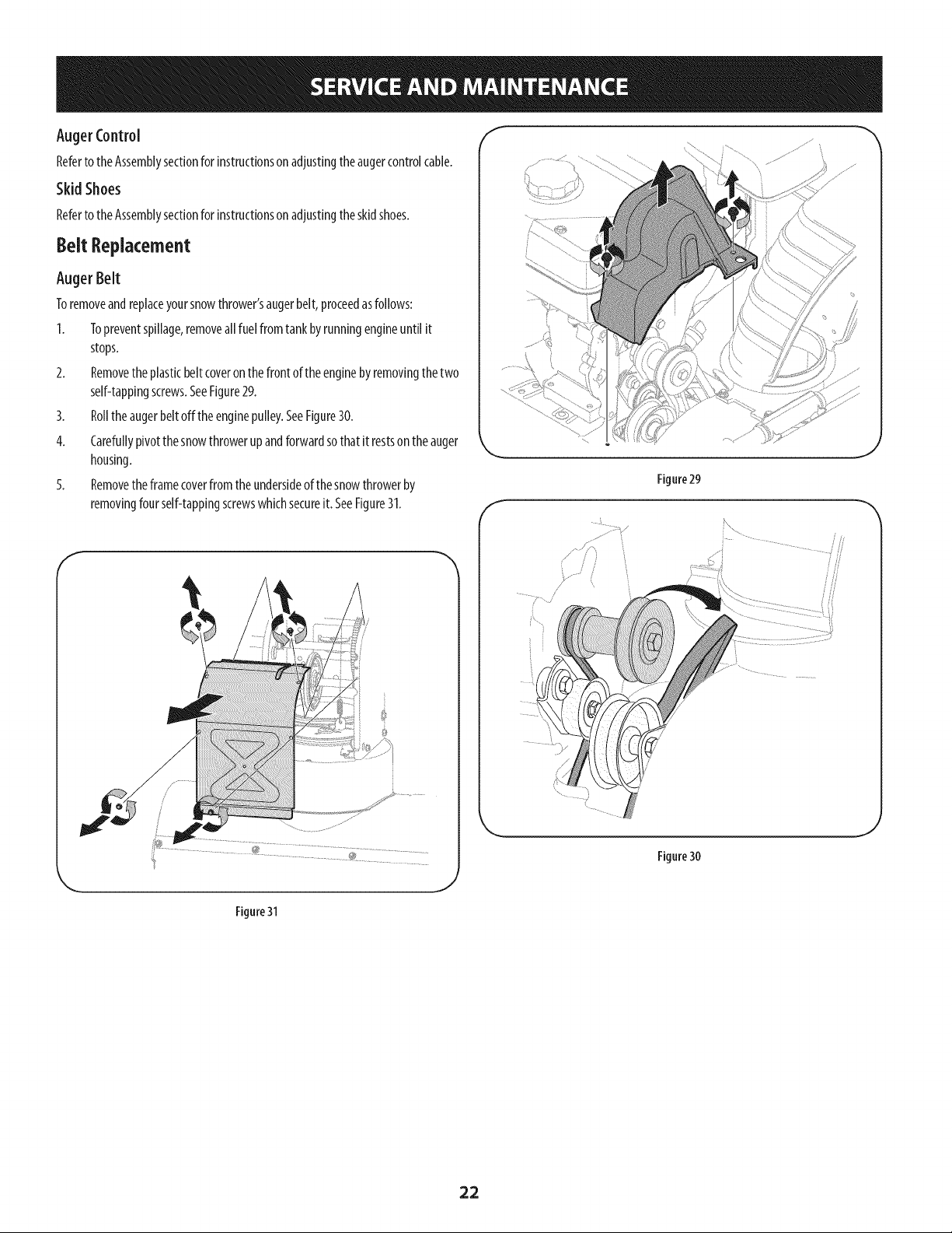
8eR Replacement
Auger Belt
Toremoveandreplaceyoursnowthrower'saugerbelt,proceedasfollows:
1. Topreventspillage,removeall fuel fromtank byrunningengineuntil it
stops.
2. Removethe plasticbelt coveronthefront of theenginebyremovingthetwo
self-tappingscrews.SeeFigure29.
3. Rollthe augerbeltoffthe enginepulley.SeeFigure30.
4. Carefullypivotthe snowthrowerupandforwardsothat it restsonthe auger
housing.
5. Removethe framecoverfromthe undersideof thesnowthrowerby
removingfourself-tappingscrewswhichsecureit. SeeFigure31.
f
Figure29
J
f
i .................
Figure30
J
Figure 31
22
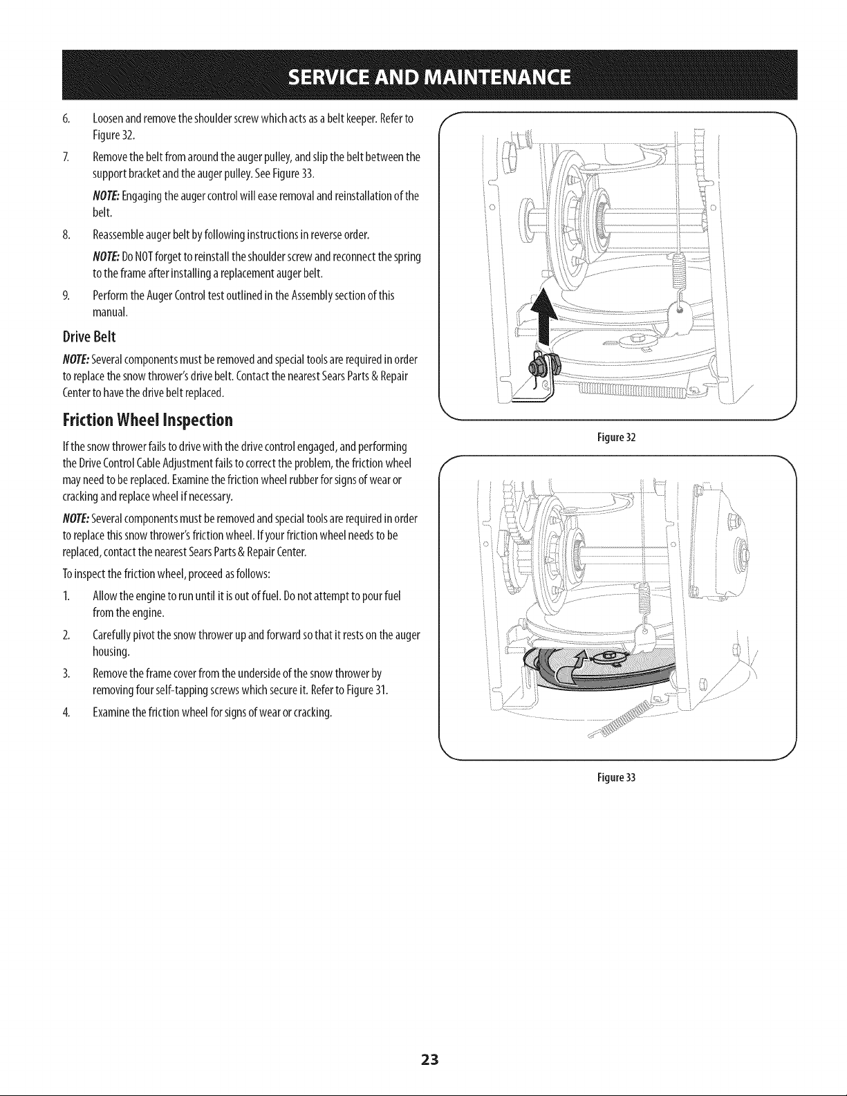
8.
Loosenandremovetheshoulderscrewwhichactsasabelt keeper.Referto
Figure32.
Removethe belt fromaroundtheaugerpulley,andslipthebelt betweenthe
supportbracketandtheaugerpulley.SeeFigure33.
NOTE:Engagingthe augercontrolwill easeremovalandreinstallationof the
belt.
Reassembleaugerbeltbyfollowinginstructionsinreverseorder.
flOTE:DoNOTforgetto reinstalltheshoulderscrewandreconnectthespring
to theframeafterinstallingareplacementaugerbelt.
Performthe AugerControltestoutlinedinthe Assemblysectionof this
manual.
Drive Belt
flOTE:Severalcomponentsmustberemovedandspecialtoolsarerequiredin order
to replacethesnowthrower'sdrivebelt.ContactthenearestSearsParts& Repair
Centerto havethe drivebelt replaced.
FrictionWheel inspection
If thesnowthrowerfailsto drivewith thedrivecontrolengaged,andperforming
theDriveControlCableAdjustmentfailsto correctthe problem,thefrictionwheel
mayneedto bereplaced.Examinethefrictionwheelrubberforsignsof wearor
crackingandreplacewheelif necessary.
flOTE:Severalcomponentsmustberemovedandspecialtoolsarerequiredin order
to replacethissnowthrower'sfrictionwheel.Ifyourfrictionwheelneedsto be
replaced,contactthe nearestSearsParts& RepairCenter.
Toinspectthefrictionwheel,proceedasfollows:
1. Allowtheengineto rununtil it isout of fuel.Donotattemptto pourfuel
fromtheengine.
2. Carefullypivotthe snowthrowerupandforwardsothat it restson theauger
housing.
3. Removethe framecoverfromthe undersideof thesnowthrowerby
removingfourself-tappingscrewswhichsecureit. Referto Figure31.
4. Examinethe frictionwheelforsignsof wearor cracking.
Figure32
i •
:_ /
Figure33
23
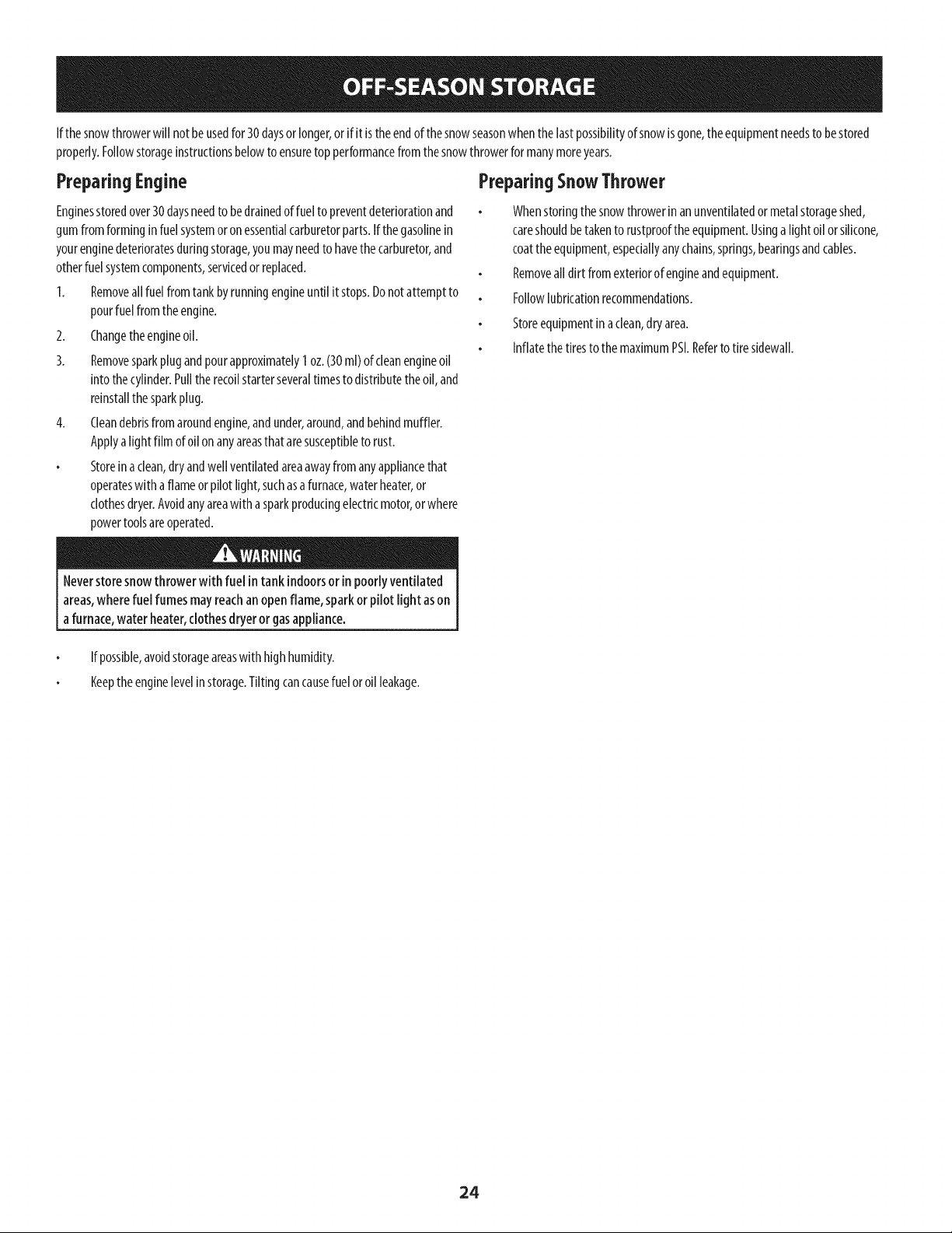
If thesnowthrowerwill notbeusedfor 30daysor longer,or if it is theendof thesnowseasonwhenthelastpossibilityof snowisgone,theequipmentneedsto bestored
properly.Followstorageinstructionsbelowto ensuretopperformancefrom thesnowthrowerformanymoreyears.
PreparingEngine
Enginesstoredover30daysneedto bedrainedof fuel to preventdeteriorationand
gumfromforminginfuel systemoron essentialcarburetorparts.If thegasolinein
yourenginedeterioratesduringstorage,youmayneedto havethe carburetor,and
otherfuelsystemcomponents,servicedorreplaced.
1. Removeall fuel fromtankbyrunningengineuntil it stops.Donot attemptto
pourfuelfrom theengine.
2. Changetheengineoil.
3. Removesparkplugandpourapproximately1oz.(30ml) ofcleanengineoil
into thecylinder.Pulltherecoilstarterseveraltimesto distributetheoil, and
reinstallthe sparkplug.
4. Cleandebrisfromaroundengine,andunder,around,andbehindmuffler.
Applya lightfilm ofoil on anyareasthat aresusceptibleto rust.
Storeinaclean,dryandwell ventilatedareaawayfromanyappliancethat
operateswith aflameorpilot light,suchasa furnace,waterheater,or
clothesdryer.Avoidanyareawith a sparkproducingelectricmotor,or where
powertoolsareoperated.
PreparingSnowThrower
Whenstoringthe snowthrowerin anunventilatedor metalstorageshed,
careshouldbetakento rustprooftheequipment.Usinga lightoil orsilicone,
coattheequipment,especiallyanychains,springs,bearingsandcables.
Removeall dirt fromexteriorof engineandequipment.
Followlubricationrecommendations.
Storeequipmentinaclean,dry area.
Inflatethe tiresto themaximumPSI.Referto tire sidewall.
Neverstore snowthrower with fuel in tank indoorsor in poorlyventilated
areas,wherefuel fumes mayreachan openflame, sparkor pilotlight ason
a furnace,water heater,clothesdryeror gasappliance.
If possible,avoidstorageareaswith highhumidity.
Keeptheenginelevelin storage.Tiltingcancausefuelor oil leakage.
24

25
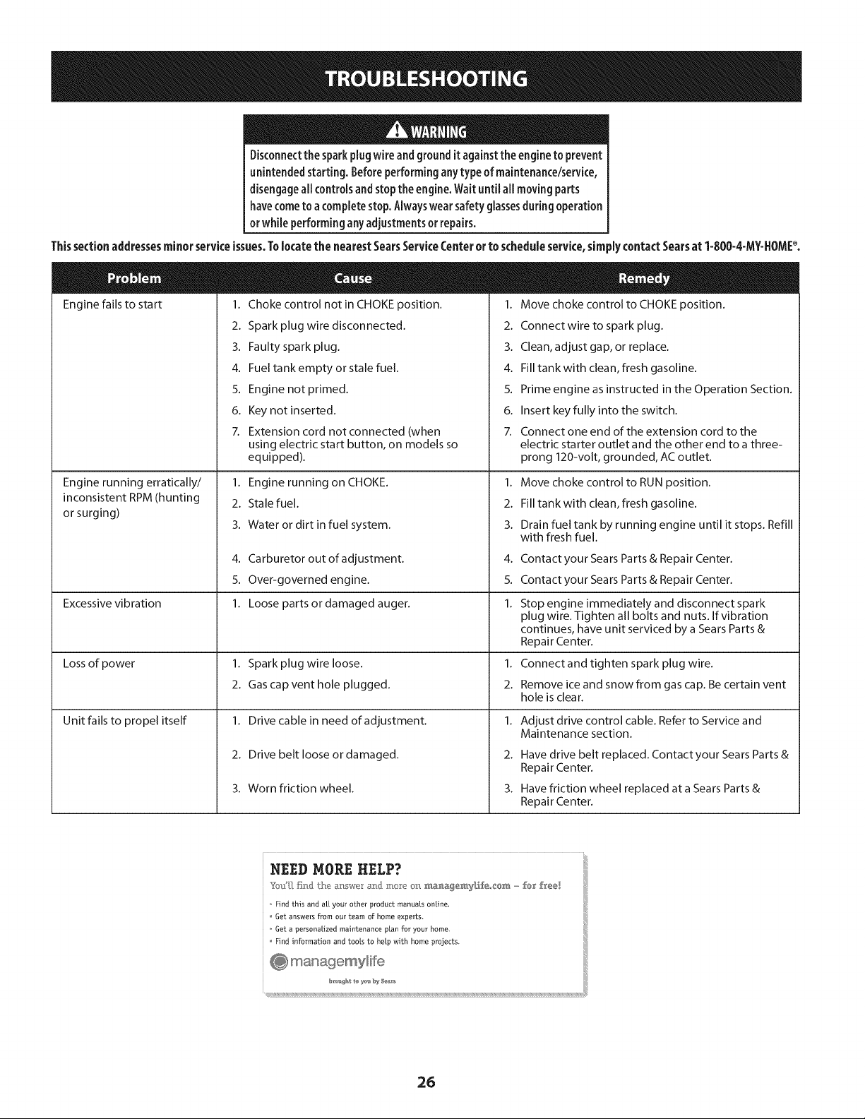
Disconnectthe sparkplug wireandgroundit againstthe engineto prevent
unintendedstarting. Beforeperforminganytypeof maintenance/service,
disengageall controls andstopthe engine.Wait until aHmovingparts
havecometo a completestop.Alwayswear safetyglassesduringoperation
or while performingany adjustmentsor repairs.
Thissectionaddressesminorserviceissues.Tolocatethe nearestSearsServiceCenterorto scheduleservice,simplycontactSearsat 1-800-4-MY=HOMP.
Engine fails to start 1.
2.
3.
4.
5.
6.
7.
Choke control not in CHOKE position.
Spark plug wire disconnected.
Faulty spark plug.
Fuel tank empty or stale fuel.
Engine not primed.
Key not inserted.
Extension cord not connected (when
1. Move choke control to CHOKE position.
2. Connectwire to spark plug.
3. Clean, adjust gap, or replace.
4. Fill tank with clean, fresh gasoline.
5. Prime engine as instructed in the Operation Section.
6. Insert key fully into the switch.
7. Connect one end of the extension cord to the
Engine running erratically/
inconsistent RPM (hunting
or surging)
Excessive vibration
Lossof power
Unit fails to propel itself
using electric start button, on models so
equipped).
1. Engine running on CHOKE.
2. Stale fuel.
3. Water or dirt in fuel system.
4. Carburetor out of adjustment.
5. Over-governed engine.
1. Loose parts or damaged auger.
1. Spark plug wire loose.
2. Gas cap vent hole plugged.
1. Drive cable in need of adjustment.
2. Drive belt loose or damaged.
3. Worn friction wheel.
electric starter outlet and the other end to a three-
prong 120-volt, grounded, ACoutlet.
1. Move choke control to RUN position.
2. Fill tank with clean, fresh gasoline.
3. Drain fuel tank by running engine until it stops. Refill
with fresh fuel.
4.
5.
1.
1.
2.
1.
2.
3.
Contact your Sears Parts & Repair Center.
Contact your Sears Parts & Repair Center.
Stop engine immediately and disconnect spark
plug wire. Tighten all bolts and nuts. If vibration
continues, have unit serviced by a Sears Parts &
Repair Center.
Connect and tighten spark plug wire.
Remove ice and snow from gas cap. Be certain vent
hole is clear.
Adjust drive control cable. Refer to Service and
Maintenance section.
Have drive belt replaced. Contact your Sears Parts &
Repair Center.
Have friction wheel replaced at a Sears Parts &
Repair Center.
NEED MORE HELP?
Find this and a[[ your other product manuals online,
Get answers from our team of home experts.
Get a personalized maintenance plan for your home.
Find information and tools to help Mth home projects.
26
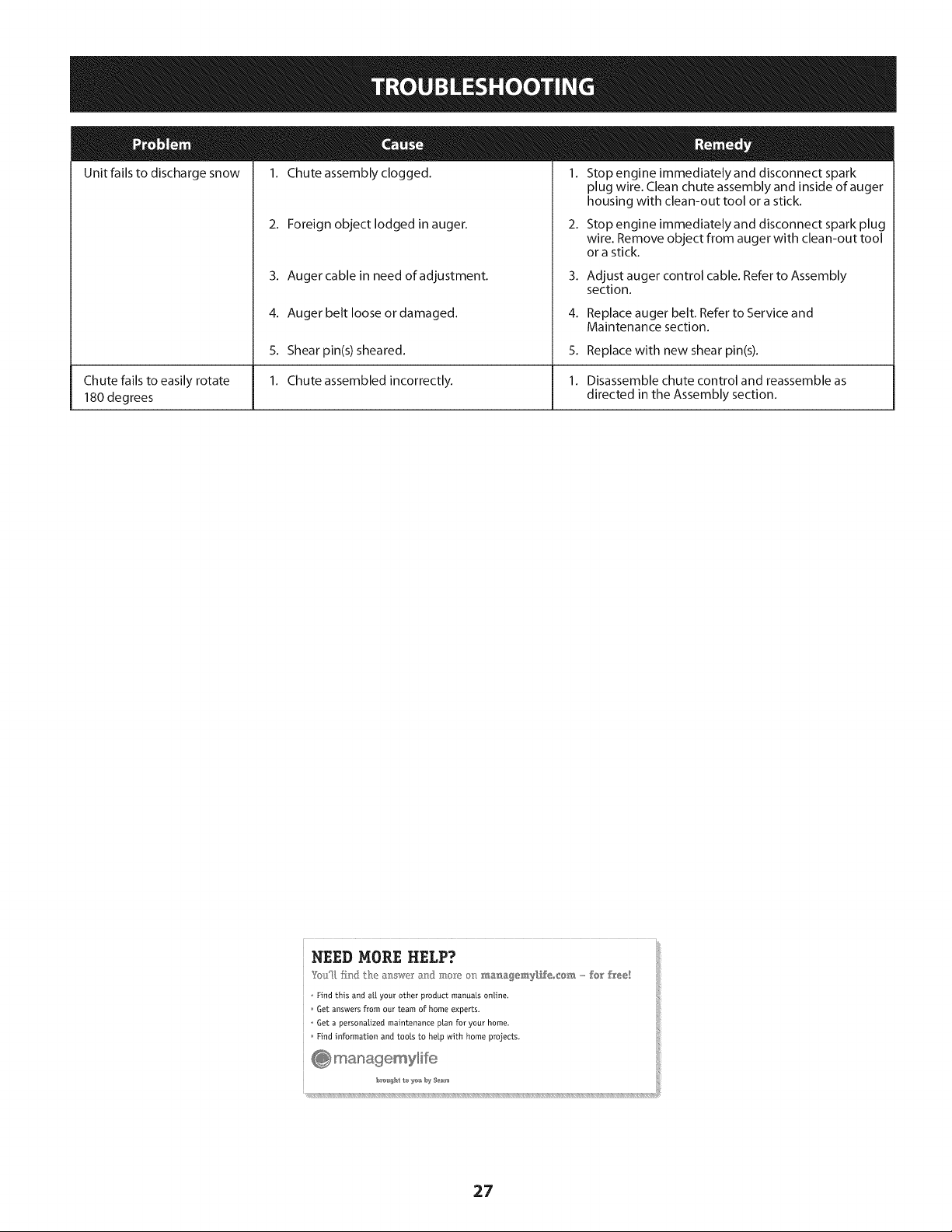
Unit fails to discharge snow
Chute fails to easily rotate
180 degrees
1. Chute assembly clogged. 1. Stop engine immediately and disconnect spark
2. Foreign object lodged in auger.
3. Auger cable in need of adjustment.
4. Auger belt loose or damaged.
5. Shearpin(s) sheared.
1. Chute assembled incorrectly.
plug wire. Clean chute assembly and inside of auger
housing with clean-out tool or a stick.
2. Stop engine immediately and disconnect spark plug
wire. Remove object from auger with clean-out tool
or a stick.
3. Adjust auger control cable. Refer to Assembly
section.
4. Replace auger belt. Refer to Service and
Maintenance section.
5. Replace with new shear pin(s).
1. Disassemble chute control and reassemble as
directed in the Assembly section.
NEED MORE HELP?
YotJU,fir_} the _: swe a_] :m,_"Yeo_:__._a_,a_emy[f_eo_@_,,,,,,,fo_' free!
o Find this and a[[ your other product manuals online.
Get answers from our team of home experts,
o Get a personalized maintenance plan for your home_
Find information and tools to help with home projects.
27
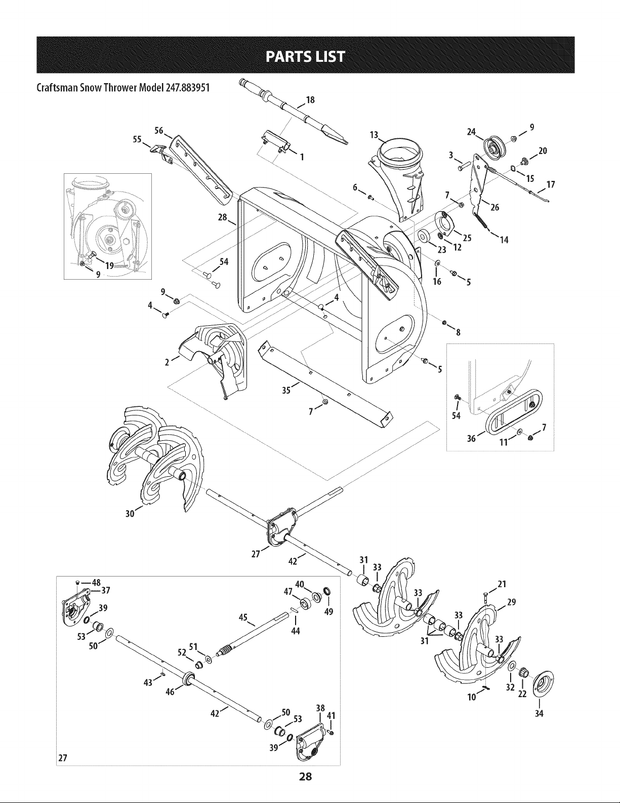
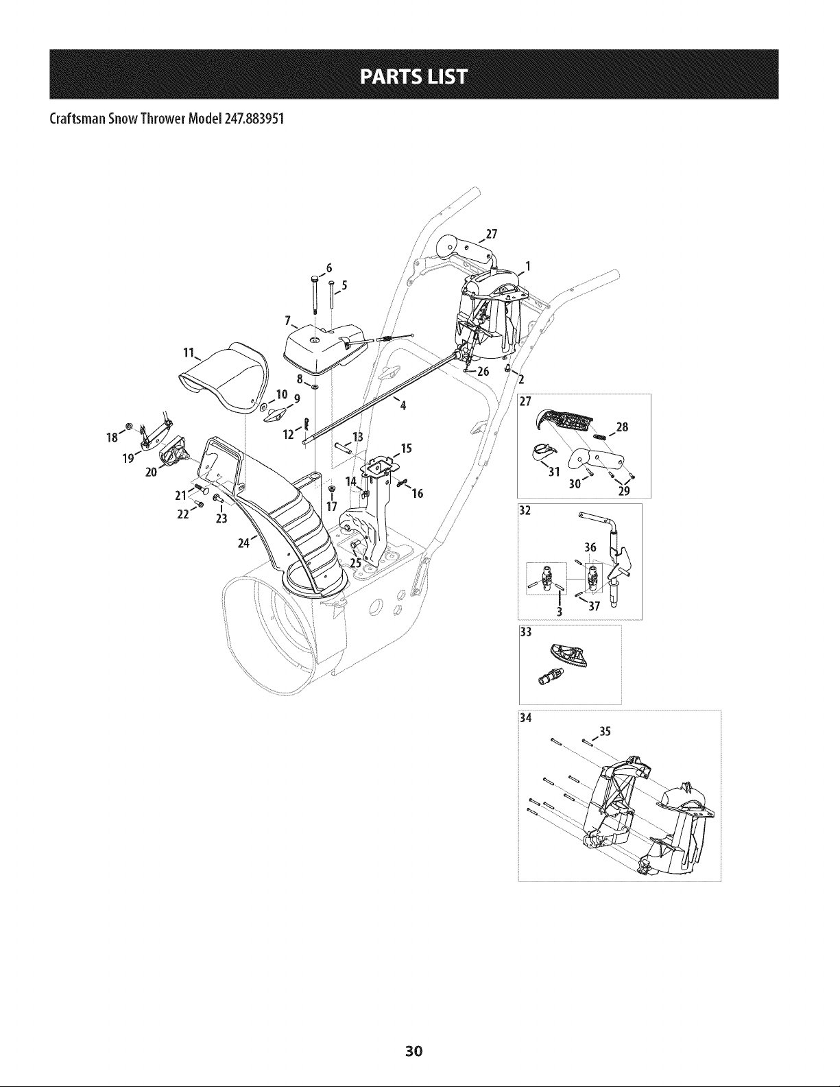
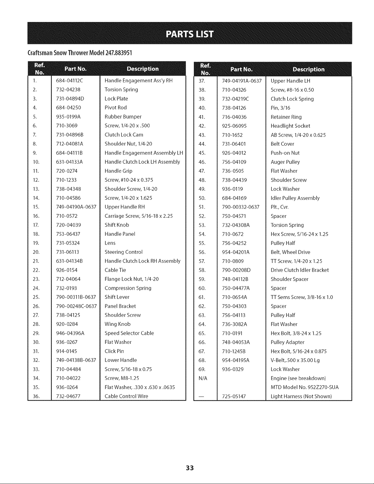
Craftsman SnowThrower Model 247.883951
18
28
13
54
7
--48
39
i27 39/ _(
28
31
31
Craftsman SnowThrower Model 247.883951
m
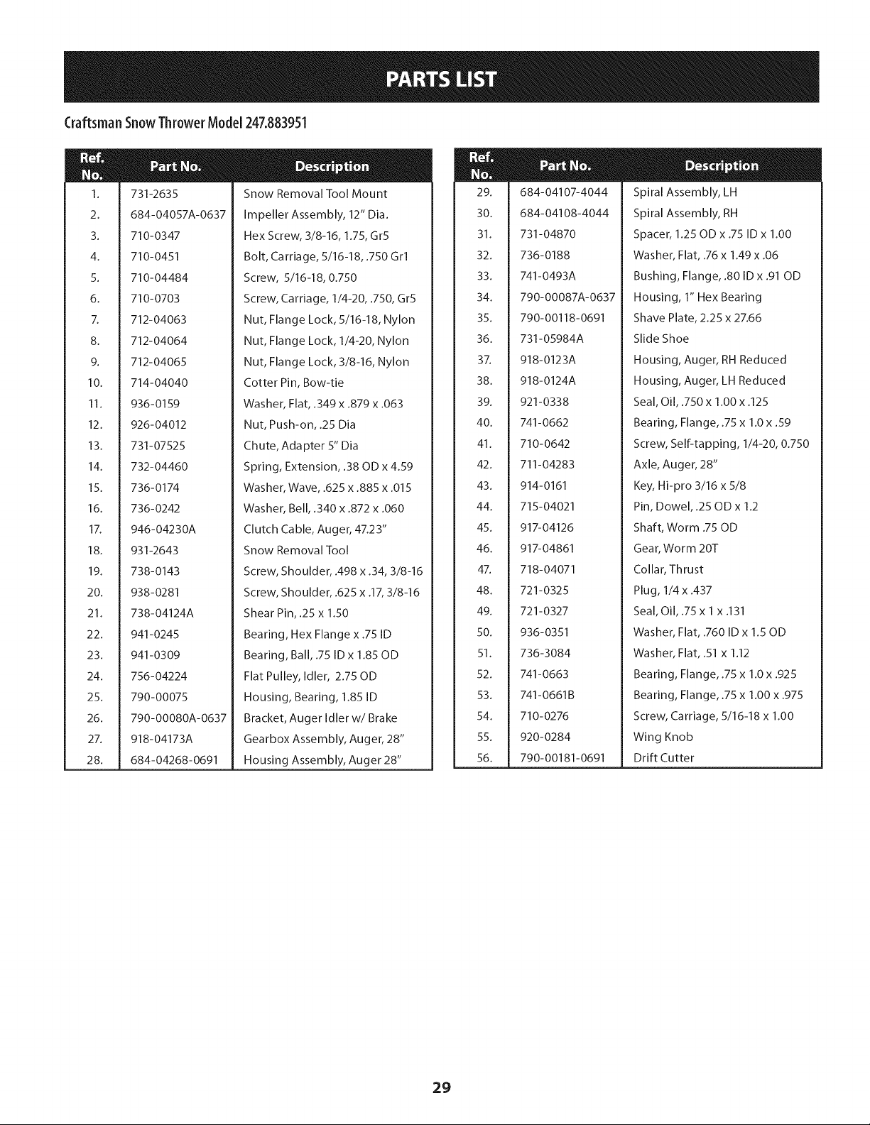
1.
2.
3.
4.
5.
6.
7.
8.
9.
10.
11.
12.
13.
14.
15.
16.
17.
18.
19.
20.
21.
22.
23.
24.
25.
26.
27.
28.
731-2635
684-04057A-0637
710-0347
710-0451
710-04484
710-0703
712-04063
712-04064
712-04065
714-04040
936-0159
926-04012
731-07525
732-04460
736-0174
736-0242
946-04230A
931-2643
738-0143
938-0281
738-04124A
941-0245
941-0309
756-04224
790-00075
790-00080A-0637
918-04173A
684-04268-0691
Snow Removal Tool Mount
Impeller Assembly, 12" Dia.
Hex Screw, 3/8-16, 1.75, Gr5
Bolt, Carriage, 5/16-18, .750 Grl
Screw, 5/16-18, 0.750
Screw, Carriage, 1/4-20, .750, Gr5
Nut, Flange Lock, 5/16-18, Nylon
Nut, Flange Lock, 1/4-20, Nylon
Nut, Flange Lock, 3/8-16, Nylon
Cotter Pin, Bow-tie
Washer, Flat, .349 x .879 x .063
Nut, Push-on, .25 Dia
Chute, Adapter 5" Dia
Spring, Extension, .38 OD x 4.59
Washer, Wave, .625 x .885 x .015
Washer, Bell, .340 x .872 x .060
Clutch Cable, Auger, 47.23"
Snow Removal Tool
Screw, Shoulder, .498 x .34, 3/8-16
Screw, Shoulder, .625 x .17, 3/8-16
Shear Pin, .25 x 1.50
Bearing, Hex Flange x .75 ID
Bearing, Ball, .75 ID x 1.85 OD
Flat Pulley, Idler, 2.75 OD
Housing, Bearing, 1.85 ID
Bracket, Auger Idler w/Brake
Gearbox Assembly, Auger, 28"
Housing Assembly, Auger 28"
M
29.
30.
31.
32.
33.
34.
35.
36.
37.
38.
39.
40.
41.
42.
43.
44.
45.
46.
47.
48.
49.
50.
51.
52.
53.
54.
55.
56.
684-04107-4044
684-04108-4044
731-04870
736-0188
741-0493A
790-00087A-0637
790-00118-0691
731-05984A
918-0123A
918-0124A
921-0338
741-0662
710-0642
711-04283
914-0161
715-04021
917-04126
917-04861
718-04071
721-0325
721-0327
936-0351
736-3084
741-0663
741-0661 B
710-0276
920-0284
790-00181-0691
Spiral Assembly, LH
Spiral Assembly, RH
Spacer, 1.25 OD x .75 ID x 1.00
Washer, Flat, .76 x 1.49 x .06
Bushing, Flange, .80 ID x .91 OD
Housing, 1" Hex Bearing
Shave Plate, 2.25 x 27.66
Slide Shoe
Housing, Auger, RH Reduced
Housing, Auger, LH Reduced
Seal, Oil, .750 x 1.00 x .125
Bearing, Flange, .75 x 1.0 x .59
Screw, Self-tapping, 1/4-20, 0.750
Axle, Auger, 28"
Key, Hi-pro 3/16 x 5/8
Pin, Dowel, .25 OD x 1.2
Shaft, Worm .75 OD
Gear, Worm 20T
Collar, Thrust
Plug, 1/4 x .437
Seal, Oil, .75 x 1 x .131
Washer, Flat, .760 ID x 1.50D
Washer, Flat, .51 x 1.12
Bearing, Flange, .75 x 1.0 x .925
Bearing, Flange, .75 x 1.00 x .975
Screw, Carriage, 5/16-18 x 1.00
Wing Knob
Drift Cutter
29
Craftsman SnowThrower Model 247.883951
/
27
! s!
/
/
/
/
27
3O
Craftsman SnowThrower Model247.883951
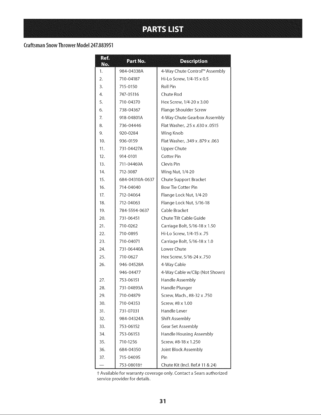
M
1.
2.
3.
4.
5.
6.
i
8.
9.
10.
11.
12.
13.
14.
15.
16.
17.
18.
19.
20.
21.
22.
23.
24.
25.
26.
27.
28.
29.
30.
31.
32.
33.
34.
35.
36.
37.
984-04338A
710-04187
715-0150
747-05116
710-04370
738-04367
918-04801A
736-04446
920-0284
936-0159
731-04427A
914-0101
711-04469A
712-3087
684-04310A-0637
714-04040
712-04064
712-04063
784-5594-0637
731-06451
710-0262
710-0895
710-04071
731-06440A
710-0627
946-04528A
946-04477
753-06151
731-04893A
710-04879
710-04353
731-07031
984-04324A
753-06152
753-06153
710-1256
684-04350
715-04095
753-08018±
4-Way Chute Control TM Assembly
Hi-Lo Screw, 1/4-15 x 0.5
Roll Pin
Chute Rod
Hex Screw, 1/4-20 x 3.00
Flange Shoulder Screw
4-Way Chute Gearbox Assembly
Flat Washer, .25 x .630 x .0515
Wing Knob
Flat Washer, .349 x .879 x .063
Upper Chute
Cotter Pin
Clevis Pin
Wing Nut, 1/4-20
Chute Support Bracket
Bow Tie Cotter Pin
Flange Lock Nut, 1/4-20
Flange Lock Nut, 5/16-18
Cable Bracket
Chute Tilt Cable Guide
Carriage Bolt, 5/16-18 x 1.50
Hi-Lo Screw, 1/4-15 x .75
Carriage Bolt, 5/16-18 x 1.0
Lower Chute
Hex Screw, 5/16-24 x .750
4-Way Cable
4-Way Cable w/Clip (Not Shown)
Handle Assembly
Handle Plunger
Screw, Mach., #8-32 x .750
Screw, #8 x 1.00
Handle Lever
Shift Assembly
Gear Set Assembly
Handle Housing Assembly
Screw, #8-18 x 1.250
Joint Block Assembly
Pin
Chute Kit (Incl. Ref.# 11 & 24)
Available for warranty coverage only. Contact a Sears authorized
service provider for details.
31
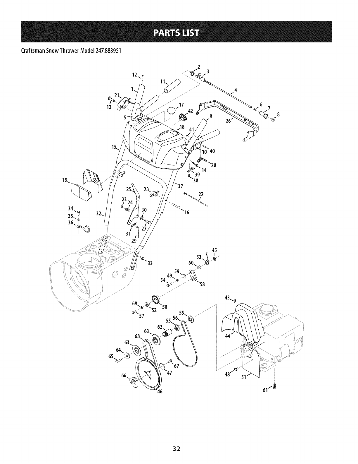
Craftsman SnowThrower Model 247.883951
12
2
3
/
31
45
61.-'_
32
Craftsman SnowThrowerModel 247.883951
m
I.
2.
3.
4.
5.
6.
7.
8.
9.
1o.
11.
12.
13.
14.
15.
16.
17.
18.
19.
20.
21.
22.
23.
24.
25.
26.
27.
28.
29.
30.
31.
32.
33.
34.
35.
36.
684-o4112c
732-04238
731-04894D
684-04250
935-0199A
710-3069
731-04896B
712-04081A
684- 04111 B
631-04133A
720-0274
710-1233
738-04348
710-04586
749-04190A-0637
710-0572
720-04039
753-06437
731-05324
731-06113
631-04134B
926-0154
712-04064
732-0193
790-00311B-0637
790-00248C-0637
738-04125
920-0284
946-04396A
936-0267
914-0145
749-04138B-0637
710-04484
710-04022
936-0264
732-04677
Handle Engagement Ass'y RH
Torsion Spring
Lock Plate
Pivot Rod
Rubber Bumper
Screw, 1/4-20 x .500
Clutch Lock Cam
Shoulder Nut, 1/4-20
Handle Engagement Assembly LH
Handle Clutch Lock LH Assembly
Handle Grip
Screw, #10-24 x 0.375
Shoulder Screw, 1/4-20
Screw, 1/4-20 x 1.625
Upper Handle RH
Carriage Screw, 5/16-18 x 2.25
Shift Knob
Handle Panel
Lens
Steering Control
Handle Clutch Lock RH Assembly
Ca ble Tie
Flange Lock Nut, 1/4-20
Compression Spring
Shift Lever
Panel Bracket
Shoulder Screw
Wing Knob
Speed Selector Cable
Flat Washer
Click Pin
Lower Handle
Screw, 5/16-18 x 0.75
Screw, M8-1.25
Flat Washer, .330 x .630 x .0635
Cable Control Wire
m
37.
38.
39.
40.
41.
42.
43.
44.
45.
46.
47.
48.
49.
50.
51.
52.
53.
54.
55.
56.
57.
58.
59.
60.
61.
62.
63.
64.
65.
66.
67.
68.
69.
N/A
749-04191A-0637
710-04326
732-04219C
738-04126
716-04036
925-06095
710-I 652
731-06401
926-04012
756- 04109
736-0505
738-04439
936-0119
684-04169
790-00332-0637
Upper Handle LH
Screw, #8-16 x 0.50
Clutch Lock Spring
Pin, 3/16
Retainer Ring
Headlight Socket
AB Screw, 1/4-20 x 0.625
Belt Cover
Push-on Nut
Auger Pulley
Flat Washer
Shoulder Screw
Lock Washer
Idler Pulley Assembly
Pit., Cvr.
750-04571
732-04308A
710-0672
756-04252
954-04201A
710-0809
790-00208D
748-04112B
750-04477A
710-0654A
750-04303
756- 04113
736-3082A
710-0191
748-04053A
710-1245B
954- 04195A
936-0329
725-05147
Spacer
Torsion Spring
Hex Screw, 5/16-24 x 1.25
Pulley Half
Belt, Wheel Drive
TT Screw, 1/4-20 x 1.25
Drive Clutch Idler Bracket
Shoulder Spacer
Spacer
TT Seres Screw, 3/8-16 x 1.0
Spacer
Pulley Half
Flat Washer
Hex Bolt, 3/8-24 x 1.25
Pulley Adapter
Hex Bolt, 5/16-24 x 0.875
V-Belt,.500 x 35.00 Lg
Lock Washer
Engine (see breakdown)
MTD Model No. 952Z270-SUA
Light Harness (Not Shown)
33
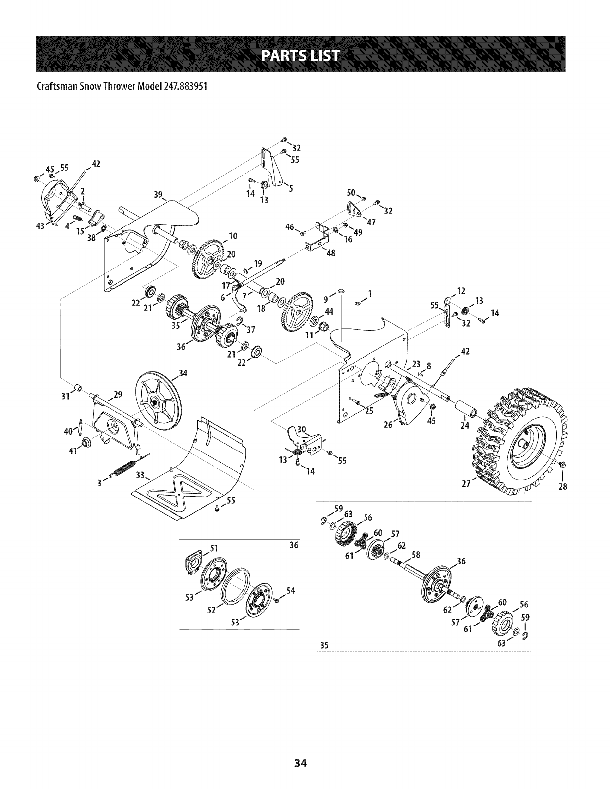
CraftsmanSnowThrowerModel247.883951
42
2
I
10
20
14 l
13
36
20
22
I
26 45 24
57
62
58
I
28
34
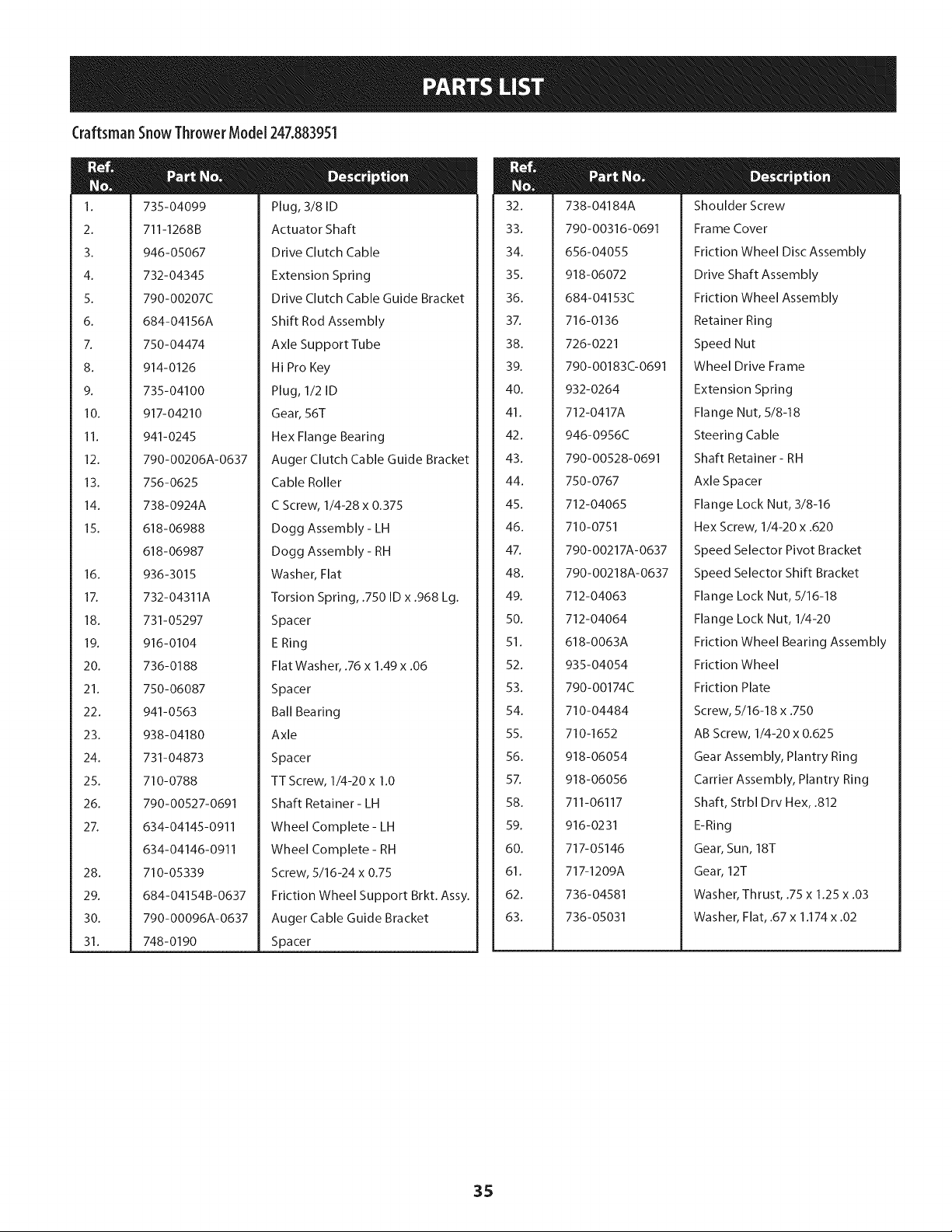
Craftsman SnowThrower Model247.883951
m
1.
2.
3.
4.
5.
6.
7.
8.
9.
10.
11.
12.
13.
14.
15.
16.
17.
18.
19.
20.
21.
22.
23.
24.
25.
26.
27.
28.
29.
30.
31.
735-04099
711-1268B
946-05067
732-04345
790-00207C
684-04156A
750-04474
914-0126
735-04100
917-04210
941-0245
790-00206A-0637
Plug, 3/8 ID
Actuator Shaft
Drive Clutch Cable
Extension Spring
Drive Clutch Cable Guide Bracket
Shift Rod Assembly
Axle Support Tube
Hi Pro Key
Plug, 1/2 ID
Gear, 56T
Hex Flange Bearing
Auger Clutch Cable Guide Bracket
756-0625
738-0924A
618-06988
618-06987
936-3015
732-04311A
731-05297
916-0104
736-0188
750-06087
941-0563
938-04180
731-04873
710-0788
790-00527-0691
634-04145-0911
634-04146-0911
710-05339
684-04154B-0637
790-00096A-0637
748-0190
Cable Roller
C Screw, 1/4-28 x 0.375
Dogg Assembly - LH
Dogg Assembly - RH
Washer, Flat
Torsion Spring, .750 ID x .968 Lg.
Spacer
E Ring
Flat Washer, .76 x 1.49 x .06
Spacer
Ball Bearing
Axle
Spacer
TT Screw, 1/4-20 x 1.0
Shaft Retainer- LH
Wheel Complete - LH
Wheel Complete - RH
Screw, 5/16-24 x 0.75
Friction Wheel Support Brkt. Assy.
Auger Cable Guide Bracket
Spacer
m
32.
33.
34.
35.
36.
37.
38.
39.
40.
41.
42.
43.
44.
45.
46.
47.
48.
49.
50.
51.
52.
53.
54.
55.
56.
57.
58.
59.
60.
61.
62.
63.
738-04184A
790-00316-0691
656-04055
918-06072
684-04153C
716-0136
726-0221
790-00183C-0691
932-0264
712-0417A
946-0956C
790-00528-0691
750-0767
712-04065
710-0751
790-00217A-0637
790-00218A-0637
712-04063
712-04064
618-0063A
935-04054
790-00174C
710-04484
710-1652
918-06054
918-06056
711-06117
916-0231
717-05146
717-1209A
736-04581
736-05031
Shoulder Screw
Frame Cover
Friction Wheel Disc Assembly
Drive Shaft Assembly
Friction Wheel Assembly
Retainer Ring
Speed Nut
Wheel Drive Frame
Extension Spring
Flange Nut, 5/8-18
Steering Cable
Shaft Retainer- RH
Axle Spacer
Flange Lock Nut, 3/8-16
Hex Screw, 1/4-20 x .620
Speed Selector Pivot Bracket
Speed Selector Shift Bracket
Flange Lock Nut, 5/16-18
Flange Lock Nut, 1/4-20
Friction Wheel Bearing Assembly
Friction Wheel
Friction Plate
Screw, 5/16-18 x .750
AB Screw, 1/4-20 x 0.625
Gear Assembly, Plantry Ring
Carrier Assembly, Plantry Ring
Shaft, Strbl Drv Hex, .812
E-Ring
Gear, Sun, 18T
Gear, 12T
Washer, Thrust, .75 x 1.25 x .03
Washer, Flat, .67 x 1.174 x .02
35
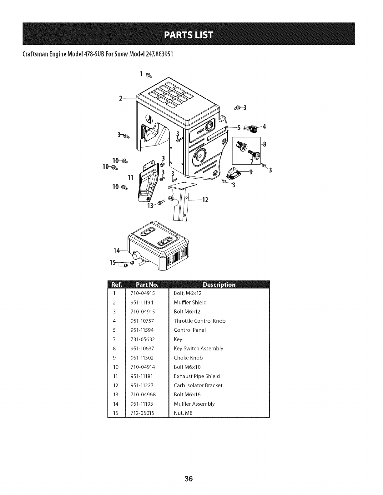
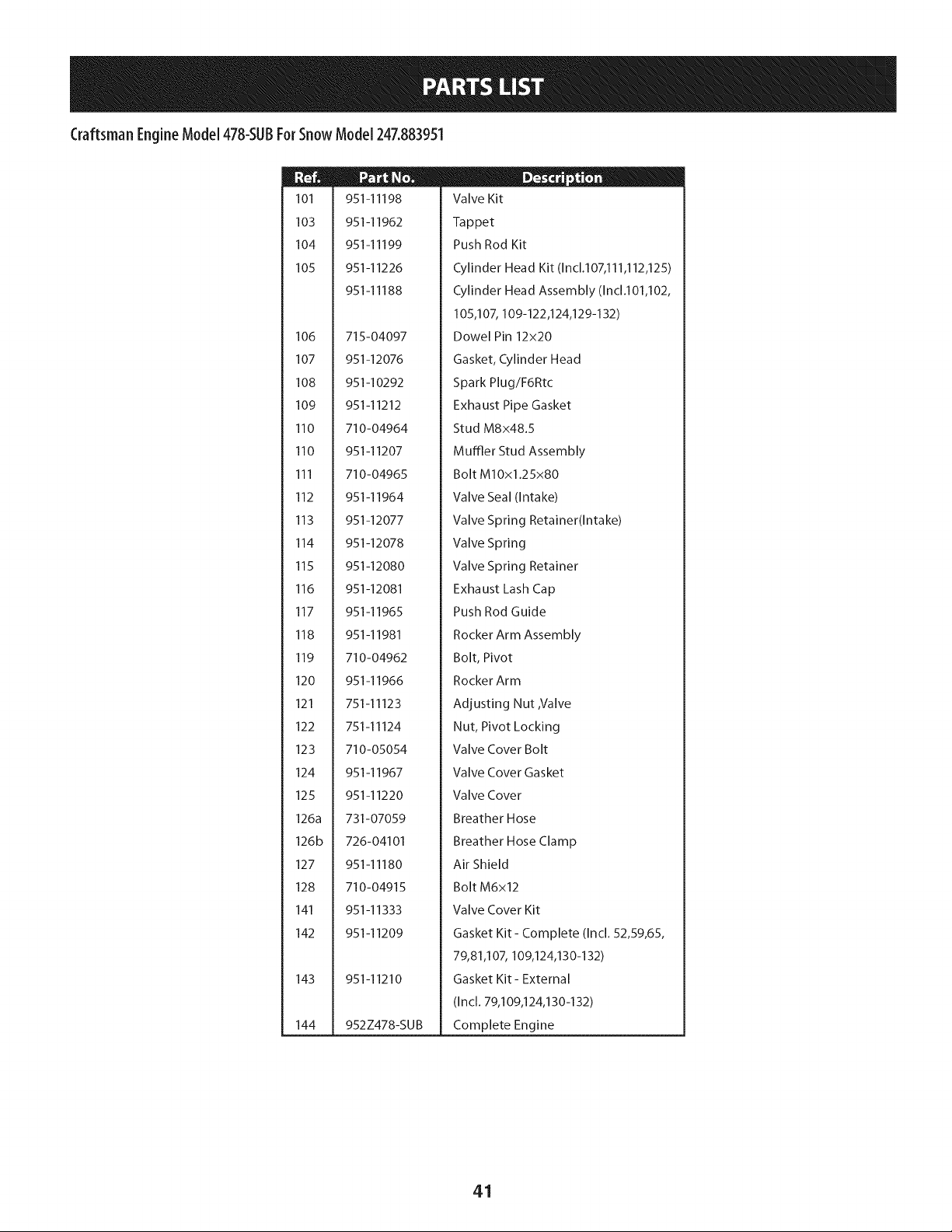
CraftsmanEngineModel478-SUBForSnowModel247.883951
1
2
3
4
5
7
8
9
10
11
12
13
14
15
710-04915
951-11194
710-04915
951-10757
951-11594
731-05632
951-10637
951-11302
710-04914
951-11181
951-11227
710-04968
951-11195
712-05015
D _ o 0
Bolt, M6x12
Muffler Shield
Bolt M6x12
Throttle Control Knob
Control Panel
Key
Key Switch Assembly
Choke Knob
Bolt M6xlO
Exhaust Pipe Shield
Carb Isolator Bracket
Bolt M6x16
Muffler Assembly
Nut, M8
36
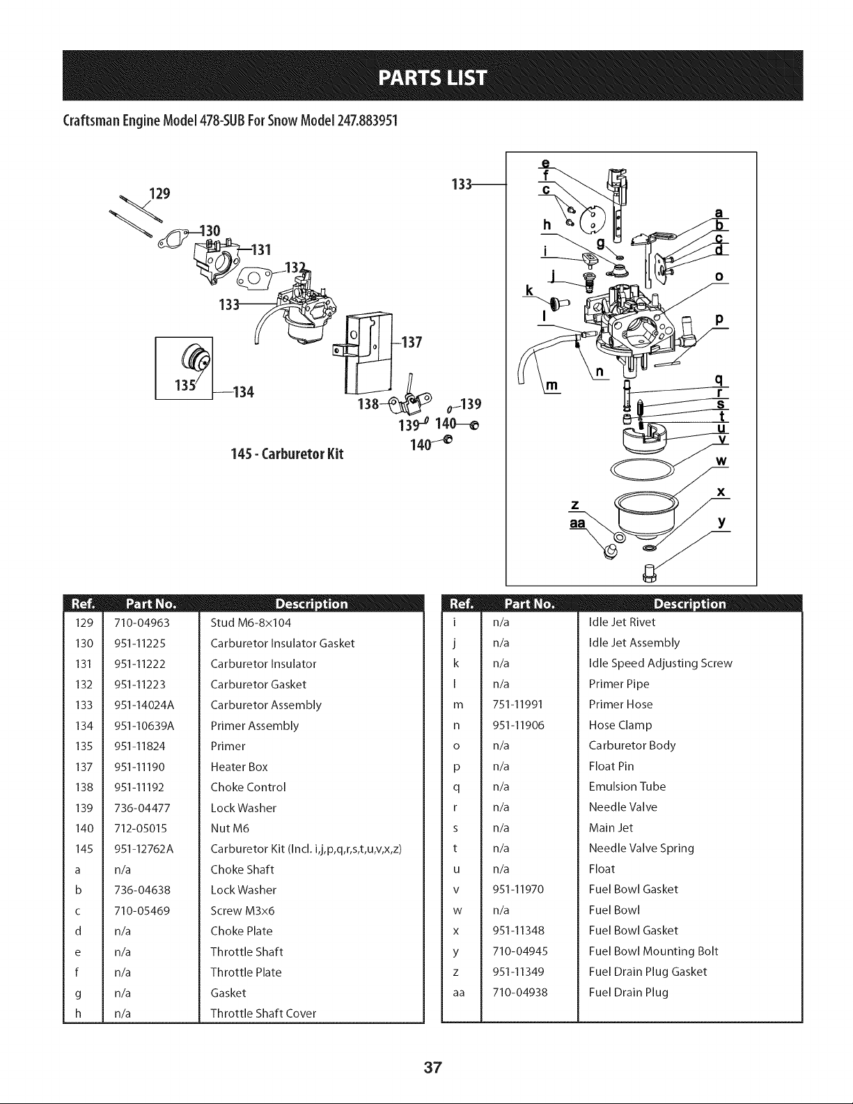
Craftsman EngineModel 478-SUBForSnow Model 247.883951
129
130
131
132
133
134
135
137
138
139
140
145
a
b
C
d
e
f
g
h
9
145- Carburetor Kit
133--
o1139
13o7o 140--_
140_
710-04963
951-11225
951-11222
951-11223
951-14024A
951-10639A
D - o 0
Stud M6-8x10⁴
Carburetor Insulator Gasket
Carburetor Insulator
Carburetor Gasket
Carburetor Assembly
Primer Assembly
951-11824
951-11190
951-11192
736-04477
712-05015
951-12762A
Primer
Heater Box
Choke Control
LockWasher
NutM6
Carburetor Kit (Incl. ij,p,q,r,s,t,u,v,x,z)
n/a
736-04638
710-05469
n/a
n/a
n/a
n/a
n/a
Choke Shaft
LockWasher
Screw M3x6
Choke Plate
Throttle Shaft
Throttle Plate
Gasket
Throttle Shaft Cover
I
J
k
I
m
n
O
P
q
r
s
t
U
V
W
X
Y
Z
aa
h
i
O
P
m
n_
n_
n_
n_
751-11991
D - o o
Idle Jet Rivet
Idle Jet Assembly
Idle Speed Adjusting Screw
Primer Pipe
Primer Hose
951-11906
n/a
n/a
n/a
n/a
n/a
n/a
n/a
951-11970
n/a
951-11348
710-04945
951-11349
710-04938
Hose Clamp
Carburetor Body
Float Pin
Emulsion Tube
Needle Valve
Main Jet
Needle Valve Spring
Float
Fuel Bowl Gasket
Fuel Bowl
Fuel Bowl Gasket
Fuel Bowl Mounting Bolt
Fuel Drain Plug Gasket
Fuel Drain Plug
37
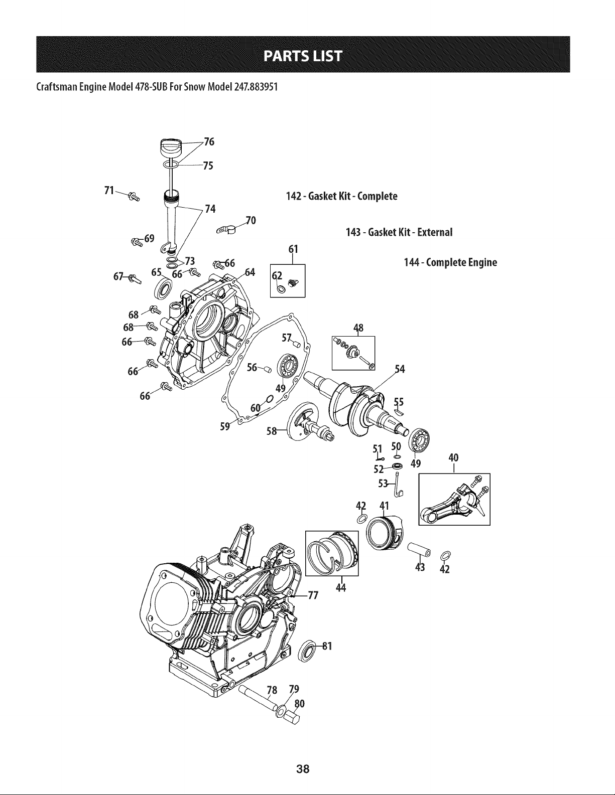
Craftsman EngineModel478-SUBForSnowModel247.883951
68
142- Gasket Kit- Complete
61
144- Complete Engine
418
42
38
Craftsman EngineModel 478-SUBForSnow Model 247.883951
4O
41
42
43
44
48
49
5O
51
52
53
54
55
56
57
58
59
6O
61
62
64
64
65
951-12066
951-12043
951 -I 1632
951-12044
951-12387
751-12068
951-12069
736-04453
714-04077
951 -I 1958
951-12071
951-11229
951-10307
715-04102
715-04092
951-12072
951 -I 1374
736-04545
951-11283
951-11577
951-12395
951-11228
951-11372
ID _ o o
Connecting Rod Assembly
Piston
Piston Pin Snap Ring
Piston Pin
Piston Ring Set
Governor Gear/Shaft Assembly
Radial Ball Bearing
Washer 8x20xO.8
Cotter Pin
Governor Seal
Governor Arm Shaft
Crankshaft Kit (Incl. 49,54,55,65,81)
Woodruff Key
Dowel Pin 9x12
Dowel Pin 7x14
Camshaft Assembly
Crankcase Cover Gasket
Washer 16x24xO.5
Oil Fill Plug Assembly
O-Ring
Crankcase Cover
Crankcase Cover Kit
(Incl. 49,59,50,64-68)
Oil Seal, 30x46x8
m
66
67
68
69
70
71
73
74
75
76
77
78
79
80
81
142
143
144
710-04971
710-04972
710-05052
710-04968
951-11320
710-05349
951-11904
951-12073
951-11381
951-11971A
951-11230
951-11187
951-11350
736-04440
710-04906
751-11498
951-11209
951-11210
952Z478-SUB
ID _ o o
Bolt M8x38
Bolt M8x45
Bolt M8x35
Bolt M6x16
Dipstick Clamp
Bolt M6x8
Oil Fill Tube O-Ring
Oil Fill Tube Assembly
Dipstick O-Ring
Dipstick Assembly
Crankcase Kit (Incl. 49,52,77,81)
Short Block Assembly
(Incl. 40-44,48-68,77-81,103,
106,107,109,111,124,130-132)
Oil Drain Pipe
Washer lOx16x1.5
Oil Drain Plug
Oil Seal 30x46x8
Gasket Kit - Complete (Incl. 52,59,65,79,
81,107,109,124,130-132)
Gasket Kit - External
(In cl. 79,109,124,130-132)
Complete Engine
39
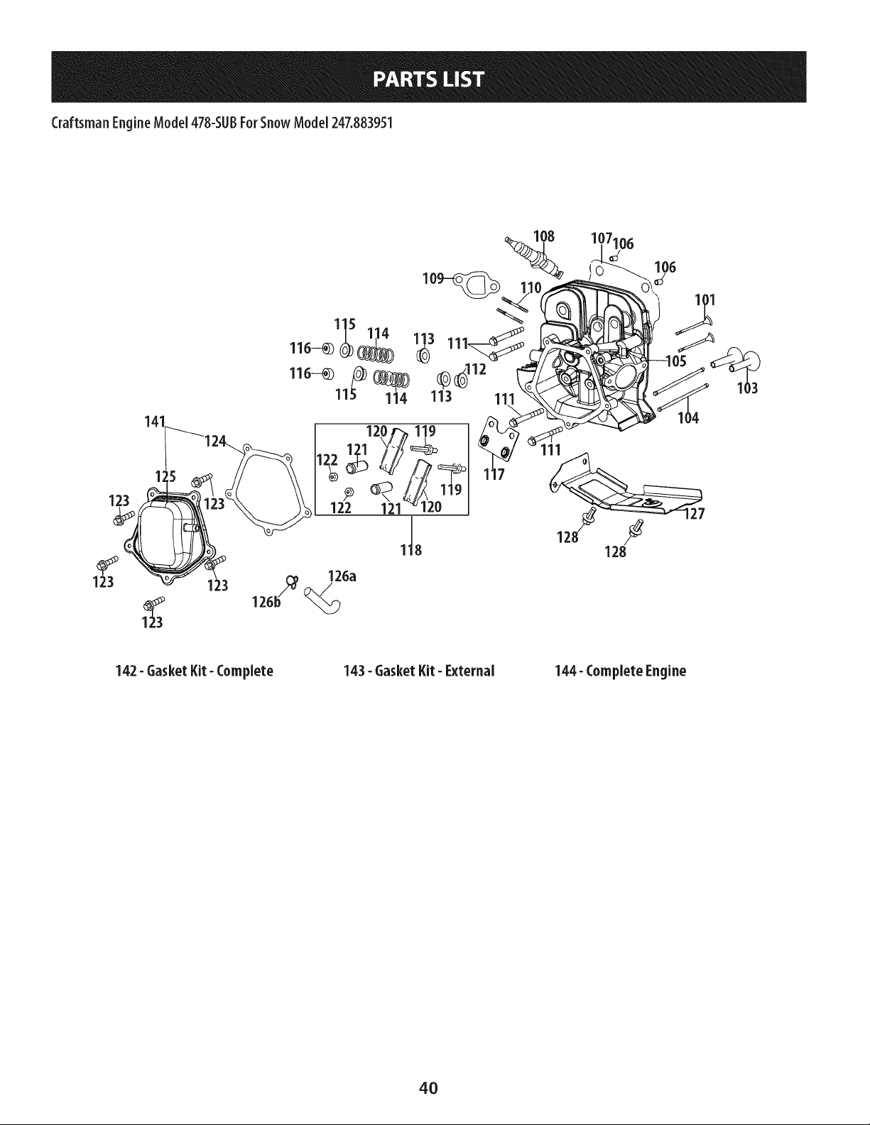
Craftsman EngineModel478-SUBForSnowModel247.883951
123
123
142- GasketKit- Complete
143- 6asker Kit- External
144- Complete Engine
4O
Craftsman EngineMode[478-SUBForSnow Mode[247.883951
n
101
103
104
105
106
107
108
109
110
110
111
112
113
114
115
116
117
118
119
120
121
122
123
124
125
126a
126b
127
128
141
142
143
144
951-11198
951-11962
951-11199
951-11226
951-11188
715-04097
951-12076
951-10292
951-11212
710-04964
951-11207
710-04965
951-11964
951-12077
951-12078
951-12080
951-12081
951-11965
951-11981
710-04962
951-11966
751-11123
751-11124
710-05054
951-11967
951-11220
731-07059
726-04101
951-11180
710-04915
951-11333
951-11209
951-11210
952Z478-SUB
D _ o o
Valve Kit
Tappet
Push Rod Kit
Cylinder Head Kit (Inc1.107,111,112,125)
Cylinder Head Assembly (Inc1.101,102,
105,107, 109-122,124,129-132)
Dowel Pin 12x20
Gasket, Cylinder Head
Spark Plug/F6Rtc
Exhaust Pipe Gasket
Stud M8x48.5
Muffler Stud Assembly
Bolt M10x1.25x80
Valve Seal (Intake)
Valve Spring Retainer(Intake)
Valve Spring
Valve Spring Retainer
Exhaust Lash Cap
Push Rod Guide
Rocker Arm Assembly
Bolt, Pivot
Rocker Arm
Adjusting Nut ,Valve
Nut, Pivot Locking
Valve Cover Bolt
Valve Cover Gasket
Valve Cover
Breather Hose
Breather Hose Clamp
Air Shield
Bolt M6x12
Valve Cover Kit
Gasket Kit- Complete (Incl. 52,59,65,
79,81,107, 109,124,130-132)
Gasket Kit- External
(In cl. 79,109,124,130-132)
Complete Engine
41

Craftsman EngineModel478-SUBForSnowModel247.883951
46
9O
91
94 96
94
P
_'-99
45
46
47
82
83
85
86
87
88
89
710-04965
951-11196
710-04967
951-11498
951-11197
951-12553
710-04969
710-04966
951-II186
951-12090
D - o o
Bolt M4x55
Electric Starter
Bolt M8x55
Ignition Coil Assembly
Ignition Coil Bolt
Alternator Assembly
Bolt M6x30
Bolt M6x8
Wire Plate
Flywheel
90
91
92
93
94
96
97
98
99
D- oo
951-11217
951-11218
712-04220
710-04968
710-04915
951-11379
951-11208
736-04455
710-04974
Cooling Fan
Starter Cup
Nut, Special, M16x1.5
Bolt M6x16
Bolt M6x12
Blower Housing
Recoil Starter
Gasket 6
Bolt M6xlO
42
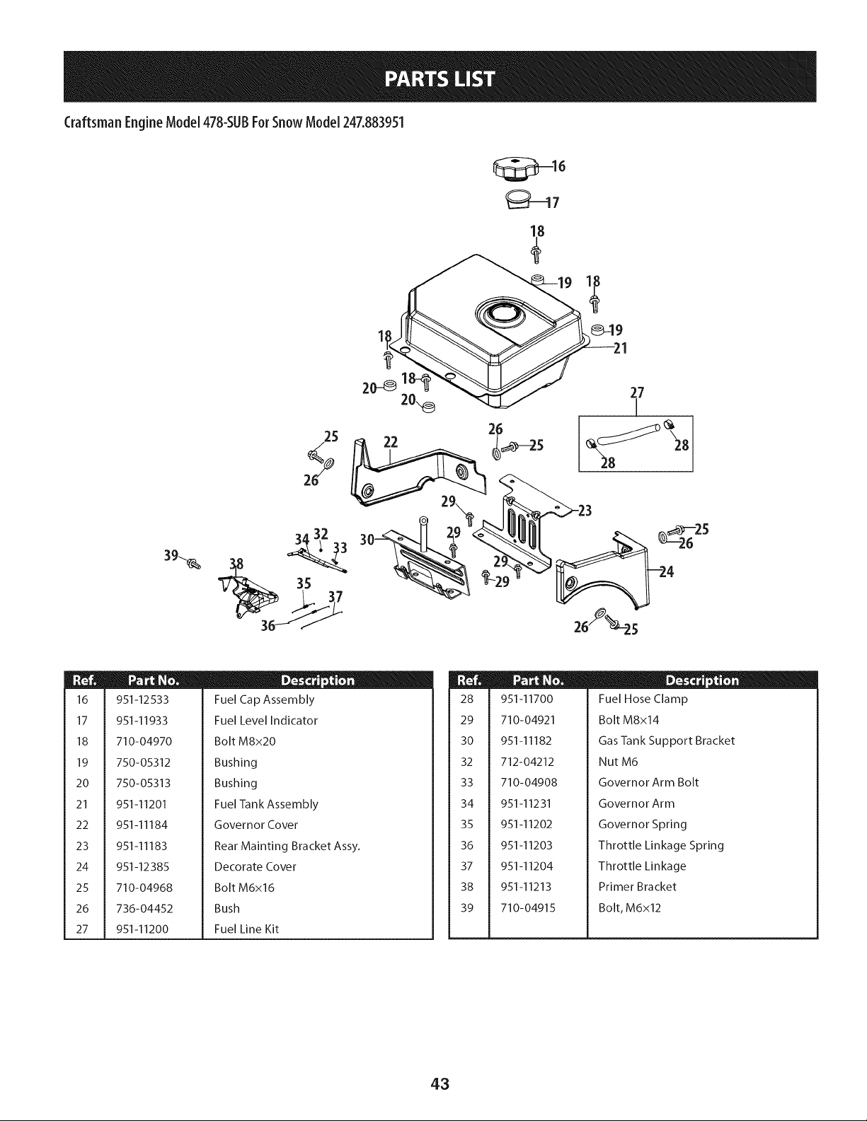
Craftsman EngineModel 478-SUBForSnow Model 247.883951
25
3A 32
16
17
18
19
20
21
22
23
24
25
26
27
951-12533
951-11933
710-04970
750-05312
750-05313
951-11201
951-11184
951-11183
951-12385
710-04968
736-04452
951-11200
D _ o o
Fuel Cap Assembly
Fuel Level Indicator
Bolt M8x20
Bushing
Bushing
Fuel Tank Assembly
Governor Cover
Rear Mainting Bracket Assy.
Decorate Cover
Bolt M6x16
Bush
Fuel Line Kit
28
29
30
32
33
34
35
36
37
38
39
951-11700
710-04921
951-11182
712-04212
710-04908
ID - o o
Fuel Hose Clamp
Bolt M8x14
Gas Tank Support Bracket
Nut M6
Governor Arm Bolt
951-11231
951-11202
951-11203
951-11204
951-11213
710-04915
Governor Arm
Governor Spring
Throttle Linkage Spring
Throttle Linkage
Primer Bracket
Bolt, M6x12
43
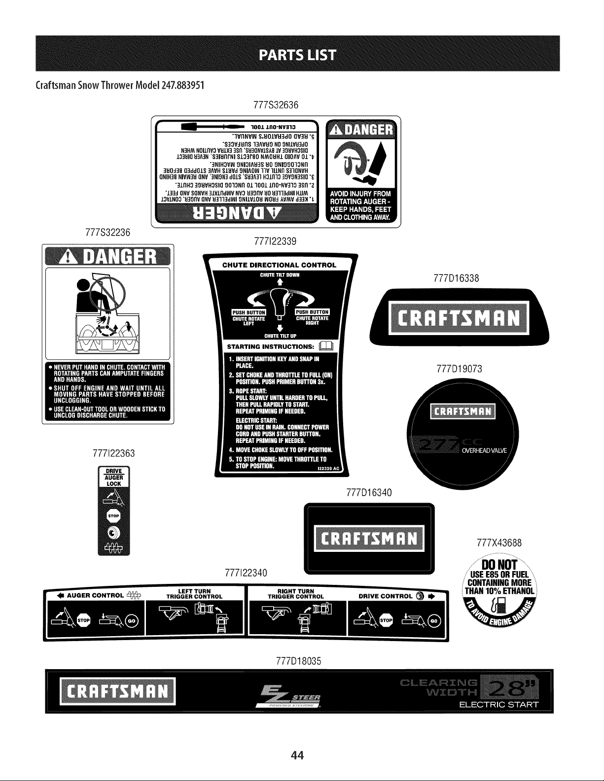
Craftsman SnowThrower ModeJ247.883951
777S32636
• -- " _ 1001 LflO-NV]lO •
"IVflNVW S,UO/VU3dO QV3U "G
"S30V_UflS 13AV_O NO 9NI/VU3dO
N3HM NOIlflVO VULX33$fl "S930NVIS19 LV 399VHOSIQ
10391093A]N 'S31HflrNI S103r80 NMOUHI OIOAV Ol "_
'3NIHOVVJ ONIOIAH3S HO ONIOOO1ONfl
390J38 03ddOIS 3AVH 81_JVdONIAOI_ IIV IIINNS310NVH
QNIH38 NIVW3H ONV ']NION3 dOIS '893A31 901nlo 30VON3810 "_
"31fiND ]9UVHOSIO OOlONfl Ol lOOl lflO-NV]19 3Sfl "Z
"133d ONVSONVH31VlfldWV NVO 930flV 90 9Bll3dWI HIlM
lOVlNOO "B]gflV ONVU3113dWI 9NllVlOU WOBd AVAAVd33H "L
777S32236
777122339
777122363
STARTING INSTRUCTIONS:
777D16338
777D19073
777D16340
777X43688
777122340
/ CONTAININGMORE
THAN 10%ETHANOL
777D18035
44
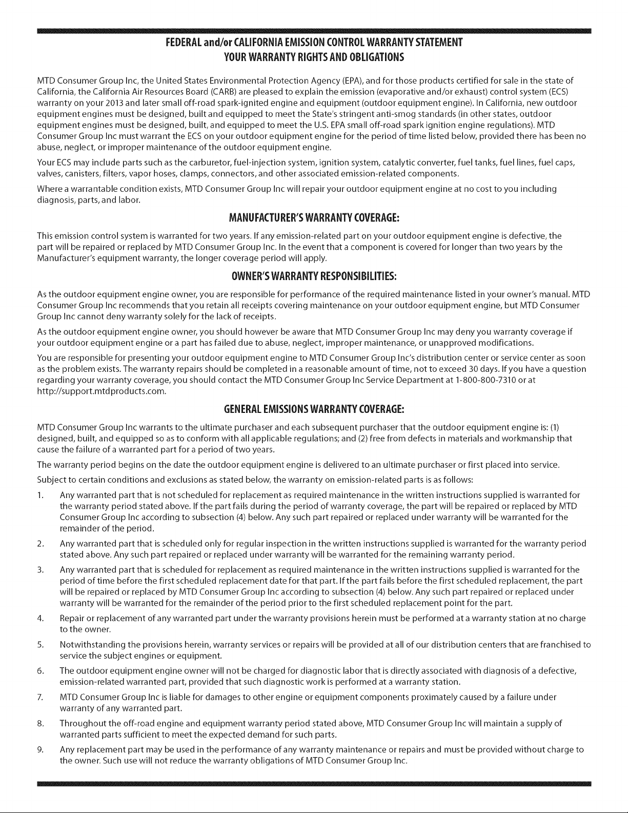
FEDERALand/or CALIFORNIAEMISSIONCONTROLWARRANTYSTATEMENT
YOURWARRANTYRIGHTSANDOBLIGATIONS
MTD Consumer Group Inc, the United States Environmental Protection Agency (EPA), and for those products certified for sale in the state of
California, the California Air Resources Board (CARB) are pleased to explain the emission (evaporative and/or exhaust) control system (ECS)
warranty on your 2013 and later small off-road spark-ignited engine and equipment (outdoor equipment engine). In California, new outdoor
equipment engines must be designed, built and equipped to meet the State's stringent anti-smog standards (in other states, outdoor
equipment engines must be designed, built, and equipped to meet the U.S. EPA small off-road spark ignition engine regulations). MTD
Consumer Group Inc must warrant the ECSon your outdoor equipment engine for the period of time listed below, provided there has been no
abuse, neglect, or improper maintenance of the outdoor equipment engine.
Your ECS may include parts such as the carburetor, fuel-injection system, ignition system, catalytic converter, fuel tanks, fuel lines, fuel caps,
valves, canisters, filters, vapor hoses, clamps, connectors, and other associated emission-related components.
Where a warrantable condition exists, MTD Consumer Group Inc will repair your outdoor equipment engine at no cost to you including
diagnosis, parts, and labor.
MANUFACTURER'SWARRANTYCOVERAGE:
This emission control system is warranted for two years. If any emission-related part on your outdoor equipment engine is defective, the
part will be repaired or replaced by MTD Consumer Group Inc. In the event that a component is covered for longer than two years by the
Manufacturer's equipment warranty, the longer coverage period will apply.
/
OWNERSWARRANTYRESPONSIBILITIES:
As the outdoor equipment engine owner, you are responsible for performance of the required maintenance listed in your owner's manual. MTD
Consumer Group Inc recommends that you retain all receipts covering maintenance on your outdoor equipment engine, but MTD Consumer
Group Inc cannot deny warranty solely for the lack of receipts.
As the outdoor equipment engine owner, you should however be aware that MTD Consumer Group Inc may deny you warranty coverage if
your outdoor equipment engine or a part has failed due to abuse, neglect, improper maintenance, or unapproved modifications.
You are responsible for presenting your outdoor equipment engine to MTD Consumer Group Inc's distribution center or service center as soon
as the problem exists. The warranty repairs should be completed in a reasonable amount of time, not to exceed 30 days. If you have a question
regarding your warranty coverage, you should contact the MTD Consumer Group Inc Service Department at 1-800-800-7310 or at
http://su pport.mtd prod ucts.com.
GENERALEMISSIONSWARRANTYCOVERAGE:
MTD Consumer Group Inc warrants to the ultimate purchaser and each subsequent purchaser that the outdoor equipment engine is: (1)
designed, built, and equipped so as to conform with all applicable regulations; and (2) free from defects in materials and workmanship that
cause the failure of a warranted part for a period of two years.
The warranty period begins on the date the outdoor equipment engine is delivered to an ultimate purchaser or first placed into service.
Subject to certain conditions and exclusions as stated below, the warranty on emission-related parts is as follows:
1. Any warranted part that is not scheduled for replacement as required maintenance in the written instructions supplied is warranted for
the warranty period stated above. If the part fails during the period of warranty coverage, the part will be repaired or replaced by MTD
Consumer Group Inc according to subsection (4) below. Any such part repaired or replaced under warranty will be warranted for the
remainder of the period.
2. Any warranted part that is scheduled only for regular inspection in the written instructions supplied is warranted for the warranty period
stated above. Any such part repaired or replaced under warranty will be warranted for the remaining warranty period.
3. Any warranted part that is scheduled for replacement as required maintenance in the written instructions supplied is warranted for the
period of time before the first scheduled replacement date for that part. If the part fails before the first scheduled replacement, the part
will be repaired or replaced by MTD Consumer Group Inc according to subsection (4) below. Any such part repaired or replaced under
warranty will be warranted for the remainder of the period prior to the first scheduled replacement point for the part.
Repair or replacement of any warranted part under the warranty provisions herein must be performed at a warranty station at no charge
to the owner.
4.
5. Notwithstanding the provisions herein, warranty services or repairs will be provided at all of our distribution centers that are franchised to
service the subject engines or equipment.
6. The outdoor equipment engine owner will not be charged for diagnostic labor that is directly associated with diagnosis of a defective,
emission-related warranted part, provided that such diagnostic work is performed at a warranty station.
7. MTD Consumer Group Inc is liable for damages to other engine or equipment components proximately caused by a failure under
warranty of any warranted part.
8. Throughout the off-road engine and equipment warranty period stated above, MTD Consumer Group Inc will maintain a supply of
warranted parts sufficient to meet the expected demand for such parts.
9. Any replacement part may be used in the performance of any warranty maintenance or repairs and must be provided without charge to
the owner. Such use will not reduce the warranty obligations of MTD Consumer Group Inc.
10. Add-onormodifiedpartsthatarenotexemptedbytheAirResourcesBoardmaynotbeused.Theuseofanynon-exemptedadd-onor
modifiedpartsbytheultimatepurchaserwillbegroundsfordisallowingawarrantyclaims.MTDConsumerGroupIncwillnotbeliableto
warrantfailuresofwarrantedpartscausedbytheuseofanon-exemptedadd-onormodifiedpart.
WARRANTEDPARTS:
The repair or replacement of any warranted part otherwise eligible for warranty coverage may be excluded from such warranty coverage if
MTD Consumer Group Inc demonstrates that the outdoor equipment engine has been abused, neglected, or improperly maintained, and that
such abuse, neglect, or improper maintenance was the direct cause of the need for repair or replacement of the part. That notwithstanding,
any adjustment of a component that has a factory installed, and properly operating, adjustment limiting device is still eligible for warranty
coverage. Further, the coverage under this warranty extends only to parts that were present on the off-road engine and equipment purchased.
The following emission warranty parts are covered (if applicable):
1. Fuel Metering System
Cold start enrichment system (soft choke)
Carburetor and internal parts (or fuel injection system)
Fuel pump
Fuel tank
2. Air Induction System
Air cleaner
Intake manifold
3. Ignition System
Spark plug(s)
Magneto ignition system
4. Exhaust System
Catalytic converter
SAI (Reed valve)
5. Miscellaneous Items Used in Above System
Vacuum, temperature, position, time sensitive valves and switches
Connectors and assemblies
6. Evaporative Control
Fuel hose
Fuel hose clamps
Tethered fuel cap
Carbon canister
Vapor lines
050790 Rev.A
Congratulationsonmakingasmartpurchase.YournewCraftsman®productisdesignedandmanufacturedforyearsof
dependableoperation.Butlikeall products,it mayrequirerepairfromtimeto time.That'swhenhavinga RepairProtection
Agreementcansaveyoumoneyandaggravation.
Here'swhat the Repair ProtectionAgreement_ includes:
[] Expertservice byour10,000professionalrepairspecialists
[] Unlimitedserviceand nocharge forpartsandlaboronallcoveredrepairs
[] Productreplacementupto $1500if yourcoveredproductcan'tbefixed
[] Discountof 25%from regularpriceof serviceandrelatedinstalledpartsnot coveredbythe agreement;also,25%off
regularpriceof preventivemaintenancecheck
[] Fasthelpby phone- wecallitRapidResolution- phonesupportfromaSearsrepresentative.Thinkof usasa"talking
owner'smanual."
Onceyoupurchasethe RepairProtectionAgreement,a simplephonecallisallthat it takesforyouto scheduleservice.You
cancallanytimedayornight,orscheduleaserviceappointmentonline.
TheRepairProtectionAgreementisa risk-freepurchase.If youcancelfor anyreasonduringthe productwarrantyperiod,
wewill provideafull refund.Or,a proratedrefundanytimeafterthe productwarrantyperiodexpires.PurchaseyourRepair
ProtectionAgreementtoday!
Somelimitations and exclusionsapply. Forpricesand additional informationinthe U.S.A.call 1-800-827-6655.
_Coveragein Canadavarieson someitems. Forfull detailscall SearsCanadaat 1-800-361-6665.
SearsInstallationService
ForSearsprofessionalinstallationof homeappliances,garagedooropeners,waterheaters,andothermajorhomeitems,in
the U.S.A.orCanadacall1-800-4-MY-HOME®.
47
Declarad6n de garantia ....................... P_gina 48
Pr_cticas operaci6n seguras ................... P_gina 49
Montaje ...................................... P_gina 53
Operad6n .................................... P_gina 59
Servido y Mantenimiento ..................... P_gina 63
Almacenamiento fuera de temporada ......... P_gina 70
Solucidn de problemas ........................ P_gina 71
Acuerdo de proteccidn para reparaciones ...... P_gina 75
Lista de piezas ................................ P_gina 28
Numero de servicio .................. Cubierta posterior
GARANTIACOMPLETACRAFTSMANPORDOSANOS
PORDOSA%Sapartirdelafechadela compra,esteproductoest_garantizadopordefectosen losmaterialesy la manodeobra.
Losproductosdefectuososser_nreparadossincostoo reemplazadossincostosila reparaci6nnoest_disponible.
GARANTIADEPORVIDALIMITADAADICIONALen la tolva de UPPERy LOWER
PARASIEMPREYCUANDOSEUTILIZAporelpropietariooriginaldespu_sdelsegundoahodesdela fechadecompra,elconductosuperioreinferiordeeste
quitanievesest_ngarantizadoscontracualquierdefectodematerialesomanodeobradebeserverificadoporunproveedordeservicioautorizadoSears.Con
elcomprobantedecompra,ustedrecibir_unarampanuevadeformagratuita.Ustedesresponsableporel costode lamanodeobradeinstalaci6ny otros
gastosocasionadosparaverificareldefect&
Paraobtenerinformaci6nsobreelalcancedelagarantiay solicitarlareparaci6no elreemplazo,visiteel sitioWeb:www.craftsman.com
EstagarantiacubreI]NICAMENTElosdefectosenlosmaterialesyen la manodeobra.EstagarantiaNOcubre:
Elementosno renovablesquepuedendesgastarseporel usonormal,duranteelplazodela garantia,incluyendoentreotros,lasbarrenas,laspaletasde
lasbarrenas,loscortadoresdedesplazamiento,laszapatasantideslizantes,laplacaderaspado,lospasadoresdecuchilla,labujia,elfiltro deaire,las
correasyel filtro deaceite.
Serviciosde mantenimientoest_ndar,cambiosdeaceiteo afinaci6n.
Cambiodeneum_ticosoreparacionesporpinchadurasconobjetosexternoscomoclavos,espinas,toconeso vidrios.
Reemplazoo reparaci6ndeneum_ticosoruedascomoresultadodeldesgastenormal,unaccidente,ofuncionamiento
omantenimientoincorrectos.
• Reparacionesrequeridascomoresultadodelusoinadecuadoporpartedeloperador,incluyendoentreotrosel dahoocasionadoporobjetosque
impactanla m_quinay quetuercenelbastidor,el ejedelabarrena,etc.,o debidoa queelmotorrueaceleradoenexceso.
Reparacionesnecesariasdebidoanegligenciadeloperador,incluyendoentreotros,dahosmec_nicoy el_ctricoocasionadopor
unalmacenamientonoapropiado,fallaporelusodeaceitedegradoy/ocantidadnoapropiadosofallapornodarmantenimiento
alequipodeacuerdoconlasinstruccionescontenidasenelmanualdeloperador.
Limpiezaoreparacionesdelmotor(sistemadecombustible)debidasa combustiblequesedeterminaest_contaminadouoxidado(viejo).Engeneral,el
combustibledebeutilizarseenunperiodonomayorde30diasapartirdesuadquisici6n.
Eldeterioroy desgastenormaldelosacabadosexteriores,o reemplazodelaetiquetadelproducto.
Lapresentegarantiaseanulasiseutilizaesteproductoalgunavezparaprestarservicioscomercialeso siseIoalquilaa otrapersona.
Estagarantiale otorgaderechoslegalesespecificos,peroustedpodriagozardeotrosderechosen raz6ndesulugarderesidencia.
SearsBrandsManagementCorporation,HoffmanEstates,IL60179
Aceite del motor: 5W-30
Combustible: Gasolina sin plomo
Motor: MTD
© Sears Brands, LLC
Numero de modelo
Numero de serie
Fecha de compra
Registre el numero de modelo, numero de serie y fecha
de compra m_s arriba.
48
Lapresendadeeste simboloindicaquesetrata deinstrucdones
importantes de seguridadquesedebenrespetarparaevitar poneren
peligro suseguridadpersonaly/o materialy Jade otras personas.Leaysiga
todaslasinstrucdonesdeeste manualantesde poneren fundonamiento
estam_iquina.Si no respetaestasinstrucdonespodriaprovocarJesiones
personales.Cuandoyea estesimbolo, ipresteatend6n a Jaadvertenda!
PROPOSICION 65 DE CALiFORNiA
EJescapedel motorde este producto,algunosde suscomponentesy
algunoscomponentesdeJvehkulo contieneno Jiberansustandasquimkas
queeJestado de Californiaconsideraquepuedenprodudr c_incer,defectos
de nadmiento u otros probJemasreproductivos.
Estam_iquinarue construidapara setoperadadeacuerdoconJasregJas
de seguridadcontenidasen estemanual.AI igualqueconcualquiertipo
de equipo motorizado,un descuidoo error por partedel operador puede
produdr lesionesgraves.Estam_iquinaescapazde amputar manosy pies
y dearrojar objetoscon gran fuerza.Deno respetarlasinstruccionesde
seguridadsiguientesse puedenproducir lesionesgraveso la muerte.
Su responsabJlJdad--Restrinja el usodeesta m_iquinamotorizada
aJaspersonasqueJean,comprendany respetenJasadvertendase
instrucdonesqueaparecenen estemanuaJyen Jam_iquJna.
iGUARDEESTASINSTRUCCIONES!
CAPACITACIC) N
Lea,entienday cumplatodaslasinstruccionesinduidasenlam_quinayen
losmanualesantesde montarlayutiJizarJa.Guardeestemanualenun lugar
seguroparaconsultasfuturasy peri6dicas,asicomoparasolicitarrepuestos.
Leael Manualdel 0peradory sigatodasJasadvertenciase instrucdonesde
seguridad.Elfracasode hacerasipuedecausarlaheridaseriaaloperadory/o
personaspresentes.
Familiaricesecontodosloscontrolesy conelusoadecuadodelosmismos.
Sepac6modetenerlam_quinay desactivarloscontrolesr_pidamente.
Nopermitanuncaquelosniffosmenoresde 14afrosutilicenestam_quina.
Losniffosde 14afrosenadelantedebenleeryentenderlasinstrucaones
deoperaci6ny normasde seguridadcontenidasen estemanual,yen la
m_quinaydebenserentrenadosy supervisadosporunadulto.
Nuncapermitaquelosadultosoperenestam_quinasinredbirantesla
instrucci6napropiada.
Losobjetosarrojadosporlam_quinapuedenproduarlesionesgraves.
Planifiqueel patr6nenelquevaair arrojandonieveparaevitarquela
descargade materialserealicehadaloscaminos,losobservadores,etc.
Mantengaa losobservadores,ayudantes,mascotasyniffosporIo menosa
75piesde lam_quinamientraslamismaest_enfundonamiento.Detengala
m_quinasialguienseacerca.
Seaprecavidoparaevitarpatinarseocaerseespedalmentecuandooperala
m_quinaen reversa.
PREPARATWOS
Inspeccioneminuciosamenteel_ireadondeutiJizar_ielequipo.Saquetodoslos
felpudos,peri6dJcos,trineos,tablas,cablesy otrosobjetosextrahosconlosque
podriatropezaro quepodrianserarrojadosporlabarrena/impulsor.
ParaprotegerselosojosutilJcesiempreanteojosoantiparrasde seguridad
mientrasoperalam_iquJnaomientraslaajustaorepara.Losobjetos
arrojadosquerebotanpuedenproducirlesionesocularesgraves.
Nooperelam_iquinasinlavestimentaadecuadaparaestaralairelibreen
invierno.NoutilJcealhajas,bufandaslargasu otrasprendassueltasque
podrianenredarseen laspartesm6viles.Utiliceun calzadoespecialpara
superficiesresbaladizas.
Useunprolongadory untomacorrientedetrescablesconconexi6natierra
paratodaslasm_iquinasconmotoresdeencendidoel_ctrico.
Ajustelaalturade Jacajadeltomacorrienteparalimpiarlagravao las
superficiesconpiedrastrituradas.
Desengranetodaslaspalancasdecontrolantesdearrancarel motor.
Nuncaintenterealizarajustesmientrasel motorest_en marchaexceptoen
loscasosespedficamenterecomendadosenel manualdeloperador.
Dejequeel motory la m_quinaseadaptenala temperaturaexteriorantes
decomenzarasacarlanieve.
49
Manejo seguro de la gasolina
Paraevitarlesionespersonaleso daffosmaterialestengamuchocuidadocuando
trabajecongasolina.Lagasolinaessumamenteinflamableysusvaporespueden
causarexplosiones.Sisederramagasolinaencimaosobrelaropasepuedelesionar
gravementeyaquesepuedeincendiar.L_iveselapiely c_imbiesederopade
inmediato.
Utilices61olosredpientesparagasolinaautorizados.
Apaguetodoslosdgarrillos,dgarros,pipasyotrasfuentesdecombusti6n.
Nuncacarguecombustibleen la m_quinaenun espadocerrado.
Nuncasaquelatapadel combustibleni agreguecombustiblemientrasel
motorest_calienteoen marcha.
Dejequeel motorseenfrieporIo menosdosminutosantesdevolvera
cargarcombustible.
NuncaIleneenexcesoeldep6sitode combustible.Lleneel tanqueanom_s
de1/2pulgadapordebajode labasedel cuellodeIlenadodejandoespacio
paraladilatad6ndelcombustible.
Vuelvaacolocarlatapadelagasolinay ajustelabien.
Limpieel combustiblequesehayaderramadosobreelmotory elequipo.
Trasladela m_quinaaotrazona.Espere5minutosantesdeencenderel
motor.
Nuncaalmacenela m_iquinao elredpientedecombustibleen unespado
cerradodondehayafuego,chispasoluz piloto(porejemplo,hornos,
calentadoresdeagua,calefactores,secadoresde ropa,etc.).
Dejequela m_iquinaseenfrieporIo menos5 minutosantesdeguardarla.
NuncaIlenelosrecipientesen elinteriorde unvehkuloocamidno cajade
remolqueconrecubrimientospl_sticos.Coloquesiemprelosredpientesenel
pisoylejosdelvehkuloantesdeIlenarlos.
Siesposible,retireelequipoagasolinadelcami6noremolquey II_neloen
elsuelo.Siestonoesposible,Ileneel equipoenun remolqueconcontenedor
port_til,envezdedesdeunaboquilladispensadoradegasolina.
Mantengalaboquilladispensadoraencontactoconelbordedeldep6sito
decombustibleoconlaaberturadel recipienteentodomomento,hasta
terminarlacarga.Noutilke undispositivodeapertura/derredeboquilla.
FUNCIONAMIENTO
Nopongalasmanoso lospiescercade laspiezasrotatorias,en lacajadela
barrena/impulsoroen elmontajedelcanaldedescarga.Hacercontactocon
piezasgiratoriaspuederesultaren laamputad6nde manosopies.
Lapalancade controldela barrena/impulsoresundispositivodeseguridad.
Nuncaevitesufundonamiento.Dehacerlolaoperad6nde lam_quinaes
riesgosay puedeocasionarlesiones.
Laspalancasdecontroldebenfundonarbienenambasdirecdonesy
regresarautom_ticamentealaposiddnde desengranecuandoselassuelta.
Nuncaoperela m_quinasifalta un montajedelcanalo sielmismoest_
daffado.Mantengatodoslosdispositivosdeseguridadensulugaryen
funcionamlento.
Nuncaendendaelmotorenespadoscerradosoenunazonaconpoca
ventilad6n.Elescapedel motorcontienemon6xidode carbono,ungas
inodoroy letal.
Noutilicelam_quinabajolainfluendadel alcohololasdrogas.
Elsilendadoryel motorsecalientany puedencausarquemaduras.Nolos
toque.Mantengaa losniffosalejados.
Seasumamenteprecavidocuandooperelam_quinasobreunasuperfide
congravaocuandolacruce.Mant_ngasealertaporsisepresentanpeligros
ocultoso tr_nsito.
Tengacuidadocuandocambiededirecd6nocuandooperelam_iquinaen
pendientes.Nouselam_iquinaenpendientespronunciadas.
Planifiqueel patr6nenelquevaa ir arrojandonieveparaevitarquela
descargadematerialseproduzcahacialasventanas,lasparedes,los
autom6viles,etc.y evitaras[posiblesdaffosmaterialeso lesionesproduddas
porlosrebotes.
Nuncadirija ladescargahadalosniffos,losobservadoresolasmascotasni
dejequenadieseparedelantedelam&quina.
Nosobrecarguelacapaddaddelam&quinatratandodesacarlanievemuy
r&pidamente.
Nuncaopereestam_quinasinbuenavisibilidadoiluminad6n.Siempredebe
estarsegurodequeest_bienafirmadoy sujetandofirmementelasmanijas.
Camine,nuncacorra.
Cortelacorrientealabarrena/impulsorcuandotransportelam_quinao
cuandolamismanoest_enuso.
Nuncaoperela m_quinaaalta veloddaddedesplazamientosobre
superficiesresbaladizas.Mirehadaabajoyhadaarrasy tengacuidado
cuandovayamarchaarras.
Sila m_quinacomenzaraavibrardemaneraanormal,detengaelmotor,
desconecteelcabledelabujiayp6ngalademaneraquehagamasacontra
el motor.Inspecdonelam_quinaminudosamenteparavet siest_daffada.
Reparetodoslosdaffosantesdeencendery operarla m_quina.
Desengranetodaslaspalancasdecontrolydetengaelmotorantesdedejar
laposki6ndeoperad6n(detr_sde lasmanijas).Espereaquelabarrena/
impulsorsedetengapot completoantesdedestaparel montajedelcanalo
realizarajustese inspecdones.
Nuncapongalasmanosen lasaberturasdedescargaode recolecd6n.Utilke
siemprela herramientade limpiezaqueseadjuntaparadestaparlaabertura
dedescarga.Nodestapeel montajedelcanalmientraselmotorest_en
fundonamiento.Antesdedestaparlo,apagueel motorypermanezcadetr_s
de lasmanijashastaquetodaslaspartesm6vilessehayandetenido.
Uses61ounionesy accesoriosaprobadospotel fabrkante(potejemplo,
pesasparalasruedas,cadenasparalosneum_ticos,cabinas,etc.).Para
obtenerm_sinformad6nacercadeestostemas,Ilameal1-800-469-4663.
5O
Paraencendere[ motor,jalede [acuerdalentamentehastaquesienta
resistencia,[uegoja[er_pidamente.Elreplieguer_pidode[acuerdade
arranque(tensi6nde retroceso)lejalar_lamanoy elbrazohaciael motor
m_sr_pidode[oqueustedpuedesoltar.Bresu[tadopuedenserhuesos
rotos,fracturas,hematomasoesguinces.
Sisepresentansituacionesqueno est_nprevistasenestemanual,sea
cuidadosoy useelsentidocomt]n.
Parapedirrepuestososervkiohoratioparaesteproducto,Ilamea1-800-
469-4663.
MANTENIMIENTO Y ALMACENAMIENTO
Nuncaalterelosdispositivosdeseguridad.Controleperi6dkamenteque
fundonencorrectamente.Rem[tasealassecdonesdemantenimientoy
ajustedeestemanual.
Antesderealizarlalimpieza,repararorevisarlam_quina,desengrane
todaslaspalancasdecontrolydetengaelmotor.Esperea quelabarrena/
impulsorsedetengaporcompleto.Desconecteelcabledelabujiay p6ngalo
hadendomasacontrael motorparaevitarqueseendendaacddentalmente.
Controlefrecuentementequetodoslospernosy tornillosest_nbien
ajustadosparacomprobarquelam_quinaseencuentraen condiciones
segurasde fundonamiento.Adem_s,hagaunainspecd6nvisualde la
m_quinaparaverificarsiest_dafrada.
Nocambielaconfigurad6ndel reguladordel motorniaceleredemasiado
elmismo.Elreguladordel motorcontrolala veloddadm_ximasegurade
fundonamientodelmotor.
Lasplacasde raspadoy laszapatasantideslizantesqueseusancon[a
m_quinaquitanievesedesgastany sedafran.Paraprotegersuseguridad,
vefrfiquefrecuentementetodosloscomponentesy reempl_celoss61ocon
partesdelosfabricantesdeequiposoriginales(0EM).iElusode piezasque
nocumplenconlasespedficacionesdelequipooriginalpuederesultaren
rendimientoinadecuadoadem_sdeporterendesgolasegufrdad!
Reviselaspalancasdecontrolperi6dicamenteparavedficarqueengraneny
desengranenadecuadamenteyajt_stelossi esnecesado.Consultelasecd6n
deajustesdeestemanualdeloperadorparaobtenerinstrucdones.
Mantengao reemplacelasetiquetasdeseguddadeinstrucdonessegt_nsea
necesado.
Respetelasnormasreferentesa ladisposici6ncorrectay las
reglamentadonessobregasolina,aceite,etc.paraprotegerel medio
ambiente.
Antesdealmacenarlam_quinaenci@ndalaunosminutosparasacarlanieve
quehayaquedadoen lamismayparaevitaras[quesecongelelabarrena/
impulsor.
Segt]nlaComisi6nde SeguddaddeProductosparaelConsumidordelos
EstadosUnidos(CPSC)y laAgendadeProtecd6nAmbientaldelosEstados
Unidos(EPA),esteproductotieneunavidatitil mediadesiete(7)afros,6
60 horasde funcionamiento.AI finalizarlavidatitil media,adquierauna
m_quinanuevaohagainspeccionaranualmente_staporundistribuidorde
servicioautodzadoparacerdorarsedequetodoslossistemasmec_nicosy de
seguddadfuncionancorrectamentey notienenexcesivodesgaste.SinoIo
hace,puedenproducirseacddentes,lesioneso muerte
Nuncaalmacenelam_quinaoel redpientedecombustibleen unespado
cerradodondehayafuego,chispaso luzpilotocomoporejemplo,
calentadoresdeagua,hornos,secadoresderopa,etc.
Consultesiempreelmanualdeloperadorparaobtenerinstrucciones
adecuadasparaelalmacenamientofueradetemporadaVefrfique
frecuentementelaI[neadecombustible,el tanque,eltap6n,ylosaccesodos
buscandorajaduraso p6rdidas.Reemplacedesernecesafro.
Nod6arranqueal motorsi noest_labujiade encendido.
NO MODIFIQUE EL MOTOR
Paraevitarlesionesgraveso lamuerte,no modifiqueel motorbajonmguna
drcunstanda.Sicambialaconfiguraci6ndelreguladorelmotorpuede
descontrolarseyoperara veloddadesinseguras.Nuncacambielaconfigurad6nde
f_bdcadel reguladordel motor.
AVISO REFERIDO A EMISIONES
Losmotoresqueest_ncertificadosy cumplenconlasregulacionesdeemisiones
federalesEPAyde CaliforniaparaSORE(Equipospequefrostodoterreno)est_n
certificadosparaoperarcongasolinacomtinsinplomoypuedeninduirlos
siguientessistemasdecontrolde emisiones:Modificaci6ndemotor(EM)y
catalizadordetresv[as(TWC)siest_nequipadosdeesamanera.
GUARDACHISPAS
Estam_quinaest_equipadacon unmotor decombusti6ninternayno
debeset utilizadaen o cercade un terrenoagrestecubierto pot bosque,
malezaso hierbaexceptosi el sistemade escapedel motorest_equipado
conun amortiguador dechispasquecumplaconlasleyeslocaleso
estatalescorrespondientes,en casodehaberlas°
SiseutilizaunamortiguadordechispaseloperadorIodebemanteneren
condicionesde usoadecuadas.Enel EstadodeCalifornialasmedidasanteriormente
mendonadassonexigidasporley(Artkulo 4442delC6digode RecursosPtiblicos
de California).Esposiblequeexistanleyessimilaresen otrosestados.Lasleyes
federalesseaplicanen territoriosfederales.
Puedeconseguirelamortiguadorde chispasparael silenciadora trav_sdesu
distribuidorautorizadode motoresoponi_ndoseen contactoconeldepartamento
deservicios.
51
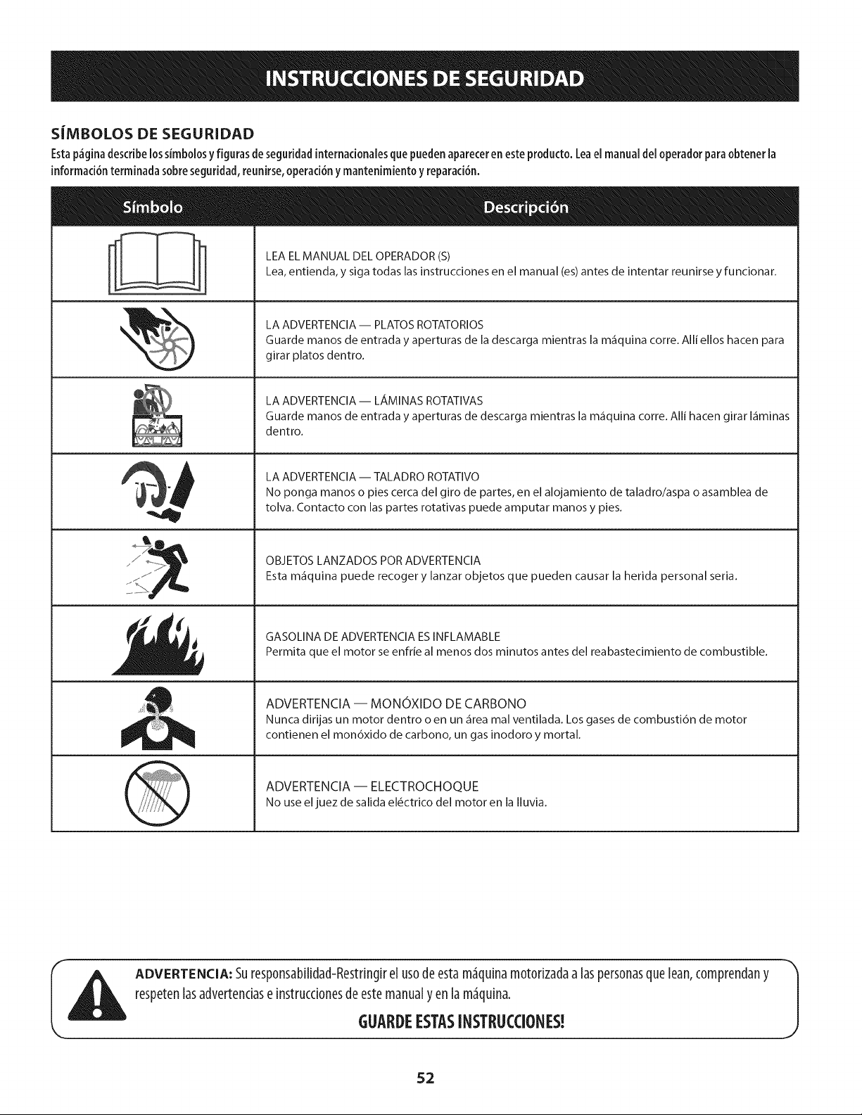
S|MBOLOS DE SEGURIDAD
Esta p_gina describe los simbolosy figuras de seguridad internacionales que pueden aparecer en este producto. Lea el manual del operador para obtener la
informad6n terminada sobre seguridad, reunirse, operad6n y mantenimiento y reparaci6n.
LEA EL MANUAL DEL OPERADOR (S)
Lea, entienda, y siga todas las instrucciones en el manual (es) antes de intentar reunirse y funcionar.
LA ADVERTENCIA -- PLATOS ROTATORIOS
Guarde manos de entrada y aperturas de la descarga mientras la m_quina corre. Alli ellos hacen para
girar platos dentro.
LA ADVERTENCIA- LAMINAS ROTATIVAS
Guarde manos de entrada y aperturas de descarga mientras la m_quina corre. Alli hacen girar I_minas
dentro.
LA ADVERTENCIA -- TALADRO ROTATIVO
No ponga manos o pies cerca del giro de partes, en el alojamiento de taladro/aspa o asamblea de
tolva. Contacto con las partes rotativas puede amputar manos y pies.
OBJETOS LANZADOS POR ADVERTENClA
Esta m_quina puede recoger y lanzar objetos que pueden causar la herida personal seria.
GASOLINA DE ADVERTENClA ESINFLAMABLE
Permita que el motor se enfrie al menos dos minutos antes del reabastecimiento de combustible.
ADVERTENCIA -- MONOXIDO DE CARBONO
Nunca dirijas un motor dentro o en un _rea real ventilada. Los gases de combusti6n de motor
contienen el mon6xido de carbono, un gas inodoro y mortal.
ADVERTENCIA -- ELECTROCHOQUE
No use eljuez de salida el6ctrico del motor en la Iluvia.
ADVERTENCIA: Suresp0nsabilidad-Restdngirel us0deestam_quinam0t0dzadaa laspersonasque Lean,c0mprendany
respetenlasadvertenciase instrucci0nesdeestemanualy enla m_quina.
J
GUARDEESTASINSTRUCCIONES!
52
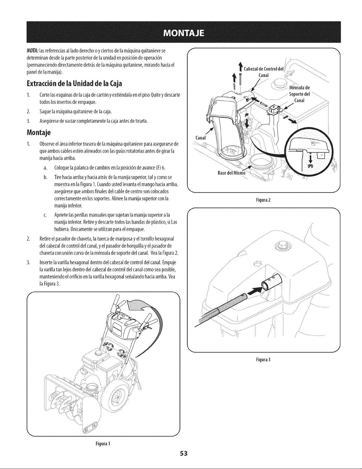
NOTA:lasreferenciasal ladoderechoo y ciertosdela m_quinaquitanievese
determinandesdelaparteposteriordela unidadenposicJdnde operaci6n
(permaneciendodirectamentedetr_sdela m_quinaquitanieve,mirandohaciael
paneldelamanija).
Extracci6nde ia Unidadde ia (aja
2.
3.
Cortelasesquinasdelacajadecart6ny exti_ndalaenelpisoQuitey descarte
todoslosinsertosdeempaque.
Saquelam_quinaquitanievede lacaja.
Asegtiresede vaciarcompletamentelacajaantesdetirarla.
Moataje
2.
3.
Observeel _reainferiortraserade la m_quinaquitanieveparaasegurarsede
queamboscablesest_nalineadosconlasgu[asrotatoriasantesdegirarla
manijahaciaarriba.
a. Coloquela palancadecambiosen laposici6ndeavance(F)6.
b. Tirehaciaarribay haciaatr_sdelamanijasuperior,tal y comose
muestraenla Figura1.Cuandoustedlevantaelmangohadaarriba,
asegtiresequeambosfinalesdelcablede centrosoncolocados
correctamenteen lossoportes.Alineelamanijasuperiorconla
manijainferior.
c. Aprietelasperillasmanualesquesujetanla manijasuperiora la
manijainferior.Retirey descartetodoslasbandasde pl_stico,siLas
hubiera.OnicamenteseutJlizanparaelempaque.
Retireelpasadorde chaveta,latuercade mariposay eltornillo hexagonal
delcabezaldecontroldelcanal,y elpasadorde horquillay elpasadorde
chavetaconuni6ncurvadela m_nsulade soportedelcanal.VealaFigura2.
Insertela varillahexagonaldentrodelcabezaldecontroldelcanal.Empuje
lavarillatan lejosdentrodel cabezaldecontroldelcanalcomoseaposible,
manteniendoelorificioen lavarillahexagonalseffalandohaciaarriba.Vea
laFigura3.
F
F
f
t CabezaldeControldel
t Canal
M6nsulade
........Soportedel
Canal
Canal
Base
f
Figura2
J
Figura3
Figura 1
53
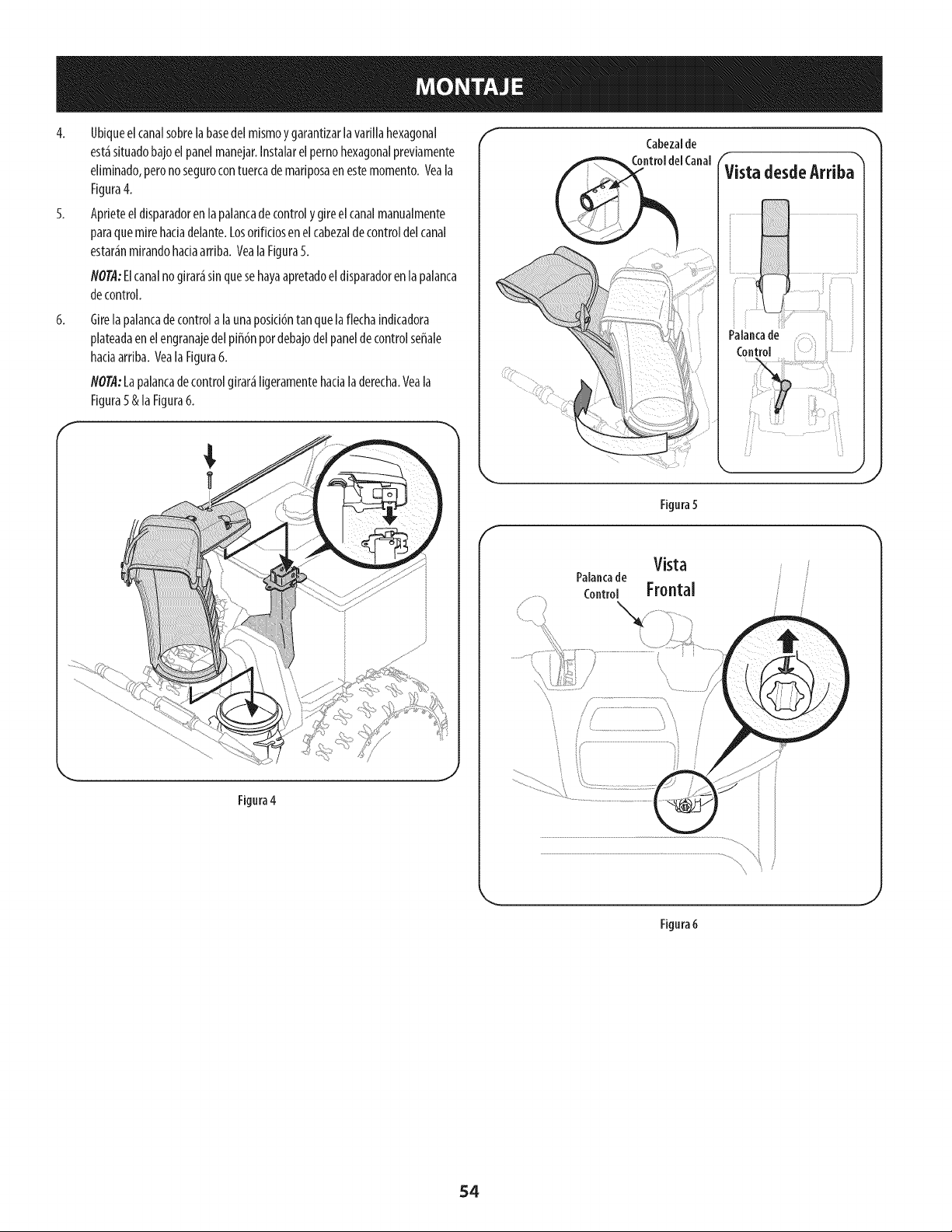
4. Ubiqueelcanalsobrelabasedelmismoygarantizarlavarlllahexagonal
est_situadobajoelpanelmanejar.Instalarelpernohexagonalpreviamente
eliminado,peronosegurocontuercademariposaenestemomento.Veala
Figura4.
5. Aprieteeldisparadorenlapalancadecontrolygireelcanalmanualmente
paraquemirehadadelante.Losorificiosenelcabezaldecontroldelcanal
estar_nmirandohadaarriba.YealaFigura5.
NO@:Elcanalnogirar_sinquesehayaapretadoeldisparadorenlapalanca
decontrol.
6.
Girelapalancadecontrola launaposici6ntan quelaflechaJndkadora
plateadaen elengranajedelpiff6npordebajodelpaneldecontrolseffale
hadaarrlba.Yeala Flgura6.
NOTA:Lapalancadecontrolgirar_ligeramentehacialaderecha.Yeala
Figura5& laFigura6.
Figura4
J
f
Cabezalde
Vista desdeArriba"
Figura5
Vista
Palancade
Control Frontal
Fignra 6
54
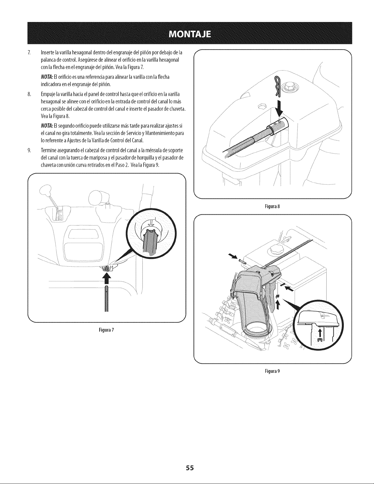
8,
Insertela vafillahexagonaldentrodelengranajedelpi_6npordebajode la
palancade control.Aseguresedealinearelorifido enlavarillahexagonal
conlaflechaenelengranajedel pi_6n.VealaFigura7.
flOT.4:Elofificioesunareferenciaparaalinearlavafillaconlaflecha
indicadoraenel engranajedel pi_6n.
Empujelavafillahaciaelpanelde controlhastaqueelorifido en lavarilla
hexagonalsealineeconel orifido en laentradade controldelcanalIo m_s
cercaposibledelcabezalde controldelcanale inserteel pasadordechaveta.
VealaFigura8.
flOTA:Elsegundoorificio puedeutilizarsem_istardepararealizarajustessi
elcanalnogiratotalmente.Yealasecci6nde Servicioy Mantenimientopara
IoreferenteaAjustesde laVarilladeControldel Canal.
Termineasegurandoelcabezaldecontroldelcanalala m#nsuladesoporte
delcanalconlatuercademariposay el pasadordehorquillay el pasadorde
chavetaconuni6ncurvaretiradosenelPaso2. VealaFigura9.
J
Figura7
/
/
, i
Figura 8
Figura 9
J
55
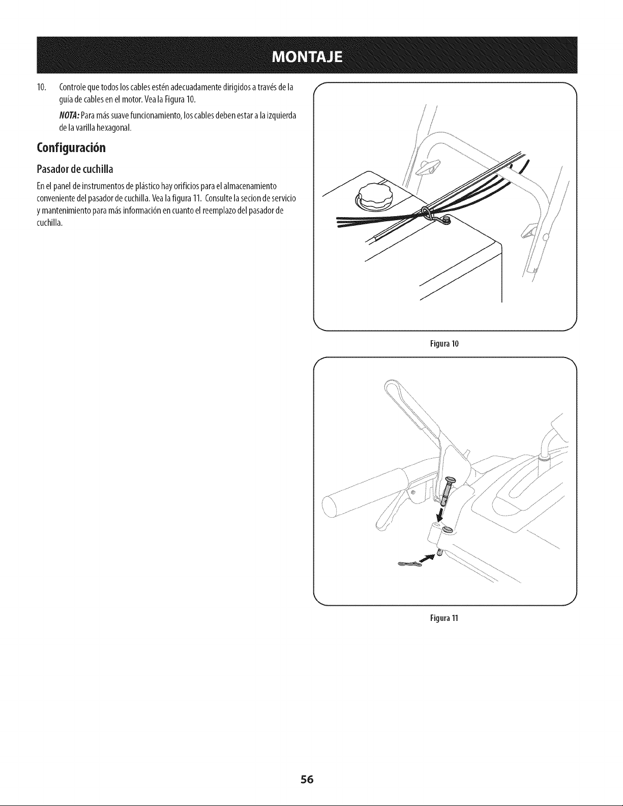
10. f"
(ontrolequetodosloscablesest_nadecuadamentedirigidosa trav_sdela
gufadecablesenel motor.YealaFigura10.
NOTA:Param_ssuavefuncionamiento,loscablesdebenestaralaizquierda
delavarillahexagonal.
Configuraci6n
Pasadorde cuchilla
Enel paneldeinstrumentosde pl_sticohayorificiosparaelalmacenamiento
convenientedelpasadordecuchilla.Yeala figura11.(onsultelasedondeservicio
y mantenimientoparam_sinformaci6nencuantoelreemplazodelpasadorde
cuchilla.
\
F
Figura10
\
Figura 11
56
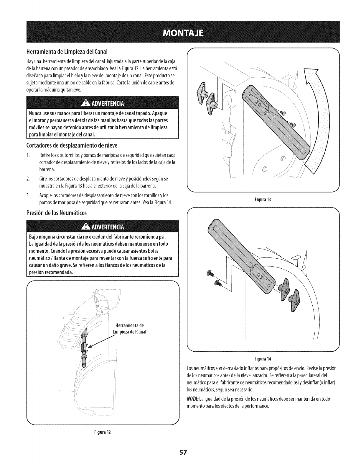
fferramienta de Limpiezadel Canal
Hayuna herramientadelimpiezadelcanaliajustadaalapartesuperiorde lacaja
de labarrenaconun pasadordeensamblado.Veala Figura12.Laherramientaest_
diseffadaparalimpiarelhieloy[anievedel montajede uncanal.Esteproductose
sujetamedianteunauni6ndecableen laf_brka. Cortelauni6ndecableantesde
operarlam_quinaquitanieve.
Nuncausesusmanospara liberarun montajede canaltapado. Apague
el motory permanezcadetr_sde lasmanijashastaquetodaslaspartes
m6vilessehayandetenido antesde utilizar la herramientade limpieza
para limpiar el montaje del canal.
Cortadoresde desplazamiento de nieve
I. Retirelosdostornillosy pomosdemariposadeseguridadquesujetancada
cortadordedesplazamientodenieveyretirelosdelosladosdelacajadela
barrena.
2. Gireloscortadoresde desplazamientodenievey posid6nelossegunse
muestraenla Figura13hadaelexteriordelacajadelabarrena.
3. Acopleloscortadoresdedesplazamientodenieveconlostorniliosylos
pomosdemariposadeseguridadqueseretiraronantes.Veala Figura14.
Presi6nde los Neum_tkos
Bajo ningunacircunstanciano excedandel fabricanterecomiendapsi.
La igualdaddela presi6nde losneum_ticosdebenmantenerseen todo
momento.Cuandola presi6nexcesivapuedecausarasientosbolas
neum_ticoI llanta de montaje parareventarcon lafuerzasuficiente para
causarun daffograve.Serefierena losflancosde losneum_ticosde la
presi6nrecomendada.
f
|ierramientade
LimpiezadelCanal
i i
//
/
Figura13
J
f
Figura14
Losneum_tkossondemasiadoinfladosparaprop6sitosdeenvio.Reviselapresi6n
de losneum_ticosantesde la nievelanzador.Serefierena laparedlateraldel
neum_ticoparaelfabricantedeneum_ticosrecomendadopsiydesinflar(oinflar)
losneum_ticos,segtinseanecesario.
NOTA:Laigualdaddelapresi6ndelosneum_ticosdebesermantenidaen todo
momentoparalosefectosde laperformance.
Figura 12
J
57

Ajustes f
Zapatas antideslizantes
LaszapatasantidesNzantesde [am_quinaquitanieveseajustanparaarribaen
f_brkaparae[envfo.Si[odesea,puedeajustar[ashadaabajoantesdehater
fundonar[am_quinaquitanieve.
Noserecomiendaqueopereestam_quinaquitanievesobregrava,yaque
esposib[eque[a m_quinaquitanievetome [agravasue[tay [a barrena
[aexpu[se,[ocua[ podrfacausar[esionespersona[eso daffar[a m_quina
quitanieve.
Sideseaquitar nievea[rasde[sue[o,e[evem_s[aszapatasantidesNzantesen
[acajade[abarrena.Refi_rasea [aFigura15.
Use[asposkionesmediao bajacuando[asuperfidequedeseeNmp[arsea
despareja,comouncam[nodegrava.
NO@:Sitienequeusar[am_quinaquitanievesobregrava,mantenga[a
zapataantidesNzanteen[aposici6nm_se[evadapara[ograrunaseparad6n
m_ximaentree[ pisoy[aplataderaspado.
Paraajustar[aszapatasantidesNzantes:
1. Afloje[ascuatrostuercashexagona[es(dosencada[ado)y lospernosde[
carro.Mueva[aszapatasantidesNzantesa [aposici6ndeseada.Vea[aFigura
15.
2. Compruebequetoda[asuperfideinferiorde [aszapatasantidesNzantesest_
contrae[sue[oparaevitarun desgastedesparejodelosmismos.
3. Vue[vaaajustarbien [astuercasy lospernos.
Pruebade Controlde [a Barrena
Antesde operarsum_quina quitanieve,lea atentamentey cump[a
todaslasinstrucdonesqueaparecena continuad6n. Reaiicetodos los
ajustesparaverificar que[a m_quinaest_operandoconseguridady
correctamente.
Compruebeel ajustedelcontrolde la barrenade la siguienteforma:
1. Elcontrolde labarrenaseencuentraenelmangoizquierdo.Consultela
Figura16elrecuadro.Cuandosesueltaelcontroldela barrenay est<_en
poski6ndesengranadaarriba,elcabledebetenermuypocojuego.NOdebe
estartens&
Enun_reabienventilada,arranqueelmotordelam_quinaquitanievesegOn
seindicaanteriormenteenestamismasecci6n.
3. Paradoenla posid6ndeloperador(detr_sdelam_quinaquitanieve),
engranelabarrena.
4. Dejela barrenaengranadaduranteaproximadamentediez(10)segundos
antesdesoltarelcontrolde labarrena.Repitaestaoperaci6nvariasveces.
5. Conlabarrenaenposid6ndesengranadaarriba,caminealfrentede la
m_quina.
6. Confirmequelabarrenahadejadodegirarporcompletoyno muestra
NINGUNsignode movimiento.SilabarrenamuestraCUALQUIER
signoderotad6n,vuelvaa laposki6ndeloperadory apagueel motor
inmediatamente.EspereaqueTODASlaspartesm6vilessedetenganantes
devolvera ajustarel controlde labarrena.
\
/
Superficie lisa
Superficie desigual
58
Figura15
f
\
Figura16
Paravolveraajustarelcabledecontrol,aflojelatuercahexagonalsuperior
en lam_nsuladelcabledela barrena.
8. Ubiquelam6nsulahaciaarribaparabrindarm_sjuego(ohaciaabajopara
aumentarlatensi6ndelcable).VealaFigura16.
9. Vuelvaaapretarlatuercahexagonalsuperior.
10. Repitalapruebade controlde labarrenaparaverificarquesehaIogradoel
ajusteadecuado.
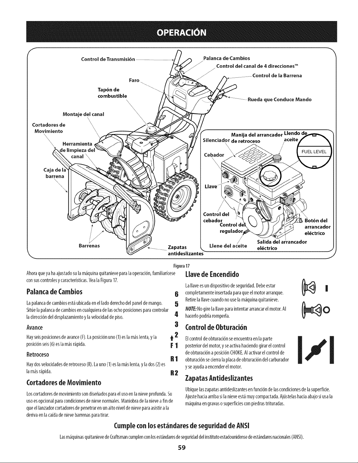
Control de Transmisi6n
Fa ro
Palanca de Cambios
Control del canal de 4 direccionesTM
/ Barrena
Tap6n de
combustible
\
\
Montaje del canal
-Rueda que Conduce Mando
Cortadores de
Movimiento
Herramienta
_ieza
Caja de I_
barrena
\
\
Barrenas
Zapatas
antideslizantes
Figura17
Ahoraqueyahaajustadosulam_quinaquitanieveparalaoperad6n,familiarkese
consuscontrolesycaracter[sticas.VealaFigura17.
Palancade Cambios 6
Lapalancade cambiosest_ubicadaen elladoderechodel panelde mango. 5
Situelapalancadecambiosen cualquierade lasochoposidonesparacontrolar
ladirecci6ndel desplazamientoy la velocidaddepiso. 4
Avarice 3
Hayseisposidonesdeavance(F).Laposici6nuno(I) eslam_slenta,y la t 2
posici6nseis(6)eslam_sr_pida. 1:1
Retroceso II 1
Haydosvelocidadesde retroceso(R).Launo(I) esla m_slenta,ylados(2)es
lam_sr_pida. 112
Cortadoresde Movimiento
Loscortadoresde movimientosondiseffadosparaelusoenlanieveprofunda.Su
usoesoptional paracondkionesdenievenormales.Maniobradelanievea fin de
queellanzadorcortadoresde penetrarenun altoniveldenieveparaasistirala
derivaenlaca[dadenievebarrenasparatirar.
Manija del arrancador Llendo d,
Silenciador de retroceso aceite
\
\
Cebador
el_ctrico
Control del
cebador
Control d
regulador
Llene del a_eite
I_lavede Encendido
LaIlaveesundispositivodeseguridad.Debeestar
completamenteinsertadaparaqueelmotorarranque.
RetirelaIlavecuandonouselam_quinaquitanieve.
NOTE:NogirelaIlaveparaintentararrancarelmotor.AI
hacerlopodriaromperla.
Control deObturaci6n
Elcontroldeobturad6nseencuentraen laparte
posteriordelmotor,y seactivahadendogirarel control
deobturad6naposici6nCHOKE.AIactivarelcontrolde
obturad6nsederralaplacadeobturad6ndelcarburador
y seayudaaencenderel motor.
ZapatasAntideslizantes
|
Ubiquelaszapatasantideslizantesenfund6nde lascondicionesde lasuperfide.
Ajustehadaarribasi lanieveest_muycompactada.Ajt_stelashadaabajosi usala
m_quinaengravaso superficiesconpiedrastrituradas.
Cumpleconlos est_ndaresde seguridadde ANSI
Lasm_qulnasquitanievedeCraftsmancumplenconlosest_ndaresdeseguridaddelinstJtutoestadounidensedeest_ndaresnacionales(ANSI).
59
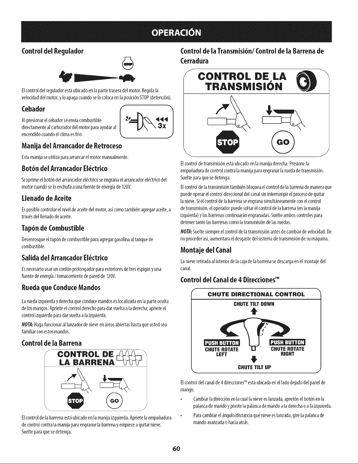
Control deiRegulador
Elcontroldel reguladorest_ubicadoen lapartetraseradelmotor.Regulala
velocidaddelmotor,y Io apagacuandoseIocolocaenlaposid6nSTOP(detend6n).
Cebador
AIpresionarelcebadorseenviacombustible
directamentealcarburadordelmotorparaayudaral
encendidocuandoelclimaesfrio.
Manijadel Arrancadorde Retroceso
Estamanijaseutilizaparaarrancarel motormanualmente.
Bot6n dei ArrancadorEi_ctrico
Sioprimeelbot6ndelarrancadorel_ctricoseengranael arrancadorel_ctricodel
motorcuandoseIoenchufaaunafuentedeenergiade 120V.
[lenado de Aceite
Esposiblecontrolarel niveldeaceitedel motor,asicomotambi_nagregaraceite,a
tray,sdelIlenadodeaceite.
Tap6nde Combustible
Desenrosqueeltap6ndecombustibleparaagregargasolinaaltanquede
combustible.
Salida delArrancadorEi_ctrico
Esnecesariousaruncord6nprolongadorparaexterioresde tresespigasy una
fuentedeenergia/ tomacorrientedeparedde120V.
Ruedaque ConduceMandos
LaruedaizquierdayderechaqueconducemandosesIocalizadaen la parteoculta
delosmangos.Aprieteelcontrolderechoparadarvueltaa laderecha;aprieteel
controlizquierdoparadarvueltaalaizquierda.
NOTA:Hagafuncionarallanzadorde nieveen_reasabiertashastaqueustedsea
familiarconestosmandos.
Elcontrolde labarrenaest_ubicadoen lamanijaizquierda.Aprietelaempuffadura
decontrolcontralamanijaparaengranarlabarrenayempieceaquitarnieve.
Suelteparaquesedetenga.
Control de ia Transmisi6n/Controlde ia Barrena de
Cerradura
/ CONTROL DE LA
TRANSMISION
J
Elcontroldetransmisi6nest_ubkadoenla manijaderecha.Presionela
empuffaduradecontrolcontralamanijaparaengranarlaruedade transmisi6n.
Suelteparaquesedetenga.
Elcontroldelatransmisi6ntambi_nbloqueaelcontrolde labarrenade maneraque
puedeoperarel controldirectionaldelcanalsininterrumpirelprocesodequitar
la nieve.Sielcontrolde labarrenaseengranasimult_neamenteconelcontrol
de transmisi6n,eloperadorpuedesoltarelcontrolde labarrena(enlamanija
izquierda)ylasbarrenascontinuar_nengranadas.Suelteamboscontrolespara
detenertanto lasbarrenascomolatransmisi6ndelasruedas.
NOTA:Sueltesiempreel controldelatransmisi6nantesde cambiardevelocidad.De
no procederas[,aumentar_eldesgastedelsistemadetransmisi6nde sum_quina.
Montaje dei Canal
Lanieveretiradaalinteriordelacajadelabarrenasedescargaenelmontajedel
canal.
Control del Canalde 4 DireccionesTM
CHUTE DIRECTIONAL CONTROl.
CHUTETILT DOWN
t
CHUTEROTATE CHUTEROTATE
LEFT HIGHT
#
CHUTETILT UP
J
Elcontroldelcanalde4 direcdonesTM est_ubicadaen elladodejadodel panelde
mango.
Cambiarladirecci6nen lacuallanieveeslanzada,apret6nelbot6nenla
palancade mandoypivotelapalancade mandoala derechao alaizquierda.
Paracambiarel_ngulo/distanciaqudnieveeslanzada,girelapalancade
mandoavanzadao haciaatr_s.
60
Herramientade Limpieza
Nuncausesusmanospara[iberarunmontajedecanaltapado. Antesde
destaparJo,apagueeJmotor y permanezcadetr_s delasmanijashastaque
todaslaspartesm6vilessehayandetenido.
Laherramientadelimpiezadelcanalest_ajustadaconvenientementea laparte
posteriordelacajade labarrenaconun pasadordeensamblado.Siseacumulan
nievey hieloenelcanaldedescargadurantelaoperad6n,procedacomoseindica
acontinuaci6nparalimpiardemaneraseguraelmontajedel canaly laaberturadel
canal:
1. Suelteelcontrolde labarrenay el controldelatransmisi6n.
2. Paradetenerel motorsaquelaIlavedeencendido.
3. Saquelaherramientadelimpiezadelpasadorquelaajustaa laparte
posteriordelacajade labarrena.
4. Useel extremoconformade palade laherramientadelimpiezapara
desplazary recogerlanievey el hieloqueseformaroncercadelconjuntodel
canal.
5. Vuelvaaajustarlaherramientadelimpiezaalpasadorde ensamblado
ubicadoenlaparteposteriorde lacajadelabarrena,insertede nuevola
Ilavedeencendidoyendendaelmotorde lam_quinaquitanieve.
6. Paradoen laposici6ndel operador(detr_sdela m_quinaquitanieve),
engraneelcontroldela barrenaduranteunossegundosparaeliminarla
nieveoel hieloquehayanquedadoenelconjuntodelcanal.
Antesde Encenderel Motor
Aceite
Gasoiina
Utilicegasolinaparaautom6viles(sinplomoo conbajocontenidodeplomopara
minimizarlosdep6sitosenlac_maradecombusti6n)conun octanajeminimode87.
Sepuedeusargasolinaconhastaun 10%deetanolo un 15%deMTBE(_termetilico
terciario-butilico).Nuncauseunamezcladeaceitey gasolinani gasolinasucia.Evite
queseintroduzcasuciedad,polvooaguaeneltanquedecombustible.NOutilice
gasolinaE85.
Carguecombustibleen un_reabienventiladay conel motorapagado.No
fumeni permitallamasochispasenel lugardondesecargacombustibleose
encuentraeldep6sitodecombustibledelmotor.
NoIleneenexcesoeltanquedecombustible.Despu_sde cargarcombustible,
asegtiresedequeeltap6ndel tanqueest_biencerradoy asegurado.
Tengacuidadode noderramarcombustibleal realizarlarecarga.El
combustiblederramadoosusvaporessepuedenincendiar.Sisederrama
combustible,aseg[iresedequeel_reaest_secaantesde arrancarel motor.
Eviteelcontactorepetidooprolongadoconlapieloinhalarlosvapores.
Tengaextremo cuidado cuandomanipulegasolina.La gasolinaes
altamente inflamabley susvaporespuedencausarexplosiones.Nunca
agreguecombustiblea la m_quinaen interioreso mientras el motorest_
calienteo en funcionamiento.Apagueloscigarrillos, cigarros,pipasy otras
fuentesde combusti6n.
1.
2.
Antesde sacarlatapaparacargarcombustible,limpiealrededor.
Eneltanquedecombustiblehayun indicadorde nivel.Lleneeltanquehasta
Ilegaralniveldecombustibledel indicador.Veala Figura10.Tengacuidado
paranoIlenarel dep6sitoenexceso.
EncendidodelMotor
Lea,comprendaysigatodaslasinstruccionesy advertenciasqueaparecen
en lam_quinayen estemanualantesde operarla.
Elmotorseenvi6conaceiteen elmotor.Controleelnlveldeaceiteantesdecada
operaci6nparaasegurarsedequehayaaceitesufidenteen elmotor.
NOTA:Asegtiresedecomprobarelmotorsobreunasuperficieniveladayconel
motorapagado.
1. Retireeltap6ndeIlenado/la varillademedici6nde niveldeaceiteylimpie
lavarilla.
2.
Inserteeltap6n/lavarillademedid6nenelcuellodeIlenadodeaceite,pero
nolaatornille.
3. Extraigaeltap6nde Ilenado/la varillade niveideaceite.Sielnivelesbajo,
agregueaceite(5W-30,conunaclasificaci6nminimade SF/SG)lentamente
hastaqueelregistromarqueentrenivelalto(H)y bajo(L).
NOT,4:NoIo Ileneenexceso.ElIlenadoexcesivode aceitepuedehacerqueel motor
generehumo,quecuestearrancarloo fallasenla bujia.
4. Vuelvaacolocareltap6n/la varillade aceitey ajusteconfirmezaantesde
arrancarel motor.
Siempremantengalasmanosy lospiesaiejadosde laspartesm6viles.No
utilice fluidos comprimidosparaarrancar. Losvaporesson inflamables.
NOTA:Dejequeelmotorsecalienteduranteunosminutostraselarranque.Elmotor
nodesarrollar_todasupotenciahastaquealcancetemperaturasoperativas.
1. Aseguresedequeelcontroldela barrenayelcontroldelatransmisi6nest_n
enposici6ndesengranada(sinpresionar).
2. InsertelaIlaveenlaranura.Asegtiresedequeentreapresi6nensulugar.No
intentegirarla Ilave.
NOTA:ElmotornopuedearrancarsilaIlavenoest_completamenteinsertadaenel
interruptordeencendido.
61
ArrancadorEl ctrko
ElarrancadoreJ_ctricoest_ equipadocon unenchufede tresterminaies
conectadosatierra y est_diseffadoparaoperarconcorrientedom_stica
de 120voltios. Debeser utilizado conun recept_culode tresterminales
correctamenteconectadoatierra en todo momento paraevitar
laposibilidad dedescargasel_ctricas.Sigatodas lasinstrucdones
cuidadosamenteparaoperarelarrancadorel_ctrico.NOutilice el
arrancadorel_ctrico bajola Iluvia.
Determinesiel cableadodesuhogaresunsistemadetrescablesconectadoatierra.
Consulteconunelectricistamatriculadosinoest_seguro.
Sicuentaconunrecept_culodeires terminales,sigalossiguientespasos.Siel
cableadodesuhogarnoeseladecuado,NOuseelarrancadorel_ctricoen ninguna
drcunstanda.
Conecteel prolongadora lasalidasituadaen lasuperfidedelmotor.Conecte
elotroextremodel prolongadoren unrecept_culodeCAconconexi6na
tierradetresterminalesde 120voltios,enun_reabienventilada.
1. Muevalapalancade controldel reguladora la posid6nFAST(r_pido,
representadaporunaliebreqJ_I ).
2. Muevalapalancadelcebadorhastalaposki6nCHOKEI,"1(encendidocon
el motorenfr[o).Siel motoryaest_caliente,ubiqueelcebadorenla posid6n
OFF.
3. Presioneel cebadortres(3)veces,asegurSndosedecubrirelorifido de
ventilad6ncuandoIo haga.Siel motorest5caliente,presioneelcebadoruna
solavez.Cubrasiempreelorifido deventilad6ncuandooprimael bot6ndel
cebador.Si hacefr[o puederesultarnecesariorepetirelcebado.
4. Jalesuavementelamanijadelarrancadorhastaquecomienceaofrecer
resistenda,luegojSlelarSpidamentey confuerzaparasuperarla
compresi6n.Nosueltela manijani permitaquesedesenganche.Vuelvala
cuerdaLENTAMENTEasuposid6noriginal.Desernecesario,repitaestepaso.
5. Mientrassecalientael motor,girelentamenteelcontroldelobturadora la
posid6nOFF(apagado).Sielmotorsedetiene,vuelvaaencenderlo,hSgalo
fundonarconelcebadoren suposici6nmediaduranteun lapsobrevey
luegogirelentamenteelcebadorhastalaposid6nOFF(apagado).
Elcabledeextensi6npuedeserde cualquierlongitud, perodebe ser
clasiflcadopara15amperiosa 125voltios,tierra y clasificadoparasu uso
en exteriores.
2. Muevala palancadecontroldelreguladoralaposid6nFAST(r_pido,
,b .
representadaporunaliebre)._
3. Muevalapalancadelcebadorhastalaposki6nCHOKEI,"1(encendidocon
elmotoren fr[o).Sielmotoryaest_caliente,ubiqueelcebadoren laposid6n
OFE
4. Presioneelcebadortres(3)veces,asegur_ndosedecubrirelorifido de
ventilad6ncuandoIohaga.Sielmotorest_caliente,presioneelcebadoruna
solavez.Cubrasiempreelorifido deventilad6ncuandooptimaelbot6ndel
cebador.Sihacefr[opuederesultarnecesariorepetirelcebado.
5. Presioneelbot6ndelarrancadorparaarrancarel motor.Unavezencendido
elmotor,suelteinmediatamenteelbot6ndelarrancador.Elarrancador
el_ctricotieneunaprotecd6ncontrasobrecargat_rmica;elsistemase
apagar_transitoriamenteparapermitirqueseenfr[eelarrancadoren caso
quesesobrecargueelarrancadorel_ctrko.
6. Mientrassecalientaelmotor,girelentamenteel controldelobturadora la
posid6nOFF(apagado).Siel motorsedetiene,vuelvaaencenderlo,h_galo
fundonarconelcebadorensuposid6nmediaduranteun lapsobrevey
luegogirelentamenteelcebadorhastalaposid6nOFF(apagado).
7. Unavezqueelmotorest_enfundonamiento,desconectedelarrancador
el_ctricoelcabledealimentad6n.Paradesconectarlo,desenchufe
siempreel extremoqueest_enchufadoal tomacorrientede paredantesde
desenchufarel extremoopuestoqueest_conectadoalmotor.
Arrancadorde Retroceso
Notire de la manija del arrancadormientrasel motor est_en marcha.
Paraevitar queel motor funcionesincontrol,nuncaIo deje sinvigilancia
mientrasest_en marcha.Apagueel motor luegode usarloysaguela llave.
Detend6ndel Motor
Dejeencendidoel motordurantealgunosminutosantesde detenerloparapermitir
quesesequelahumedadenel mismo.
1. Muevaelcontroldel reguladora laposidbnOFE
2. Retirela Ilave.AIretirarlaIlavesereducelaposibilidadde queelmotorsea
puestoenmarchasinautorizad6nmientrasel equiponoest_enuso.Guarde
laIlaveen unlugarseguro.Elmotorno puedearrancarsinlaIlave.
3. Eliminelahumedadde loscontrolesdelmotor.
Procedimientopara Engranaria Transmisi6n
1. Conel controldelestranguladoren posid6nr_pida_ (dibujode un
coneio),muevala palancade cambiosaunadelasseisposidonesde avance
(F)o delasdosposkionesde reversa(R).Selecdonelaveloddadadecuada
paraelestadode lanieveexistentey unaveloddadconlaquesesienta
c6modo.
Aprieteelcontrolde latransmisi6ncontralamanijaderecha,y la m_quina
quitanievesemover&Sudlteloy sedetendr_el movimientodela
transmisi6n.
flOT/l:NUNCAcambielaposici6ndelapalancadecambios(cambiodevelocidades
o dedirecd6ndedesplazamiento)sinsoltarprimeroelcontrolde transmisi6ny
detenerporcompletolam_quinaquitanieve.Estoproducir_undesgasteprematuro
delsistemadetransmisi6nde lam_quinaquitanieve.
Procedimientopara EngranariasBarrenas
1. Aprieteelcontrolde labarrenacontralamanijay lasbarrenasrotar_n.
Su_ltelay lasbarrenassedetendr_n.
62
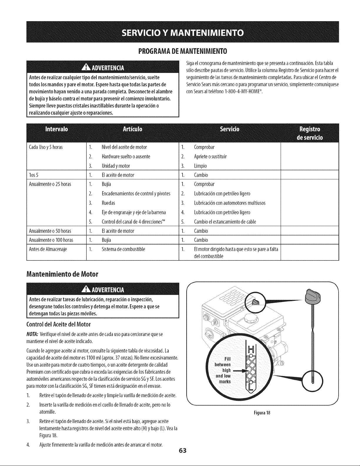
PROGRAMADEMANTENIMIENTO
Antesde realizarcualquiertipo del mantenimiento/servicio,suelte
todos losmandosy pare elmotor. Esperehastaquetodaslaspartesde
movimiento hayanvenido a unaparadacompleta. Desconecteel alambre
de bujia y b_selocontrael motor paraprevenirel comienzoinvoluntario.
Siemprellevepuestoscristalesinastillablesdurante la operaci6no
realizandocualquierajusteo reparaciones.
Sigaelcronogramade mantenJmientoquesepresentaa continuaci6n.Estatabla
s61odescribepautasde servkio.UtilicelacolumnaRegistrode Servicioparahacerel
seguimientodelastareasde mantenimientocompletadas.ParaubicarelCentrode
ServicioSearsm_scercanoo paraprogramarunservicio,simplementecomun[quese
conSearsal tel_fono1-800-4-MY-HOME®.
CadaUsoy5 horas
los5
Anualmenteo25horas
Anualmenteo50horas
Anualmenteo 100horas
AntesdeAlmacenaje
1. Niveldelaceitedemotor
2. Hardwaresueltooausente
3. Unidady motor
1. Elaceitedemotor
1. Bujia
2. Encadenamientosdecontroly pivotes
3. Ruedas
4. Ejedeengranajey ejede labarrena
5. Controldelcanalde4 direcdonesTM
1. Elaceitedemotor
1. Buj[a
1. Sistemadecombustible
1. Comprobar
2. Aprieteosustltuir
3. Limpio
1. Cambio
1. Comprobar
2. Lubricad6nconpetr61eoligero
3. Lubricaci6nconautomotoresmultiusos
4. Lubricaci6nconpetr61eoIigero
5. Cambioelestancamientode cable
1. Cambio
1. Cambio
1. Elmotordirigidohastaqueestosepareafalta
delcombustible
Mantenimientode Motor
Antesde realizartareasde lubricaci6n,reparaci6no inspecci6n,
desengranetodos loscontrolesydetenga el motor. Esperea quese
detengantodaslaspiezasm6viles.
Control del Aceite del Motor
flOTA:Verifiqueel niveldeaceiteantesde cadausoparacerciorarsequese
mantieneel niveldeaceiteindicado.
Cuandoleagregueaceitealmotor,consultelasiguientetabladeviscosidad.La
capacidaddeaceitedelmotores1100ml (aprox.37onzas).NoIleneexcesivamente.
Useunaceiteparamotordecuatrotiempos,o unaceitedetergentedecalidad
Premiumconcertificadoquecubrao excedalasexigenciasdelosfabricantesde
autom6vilesamerkanosrespectodela clasificad6ndeservicioSGy SELosaceites
paramotorconlaclasificaci6nSG,SFtienenest_designad6nen elenvase.
1. Retireeltap6ndeIlenadodeaceitey limpielavarillademedici6ndeaceite.
2. Insertela varillademedici6nenel cuellodeIlenadodeaceite,perono Io
atornille.
3. Retireeltap6ndeIlenadodeaceite.Sielnivelest_bajo,agregueaceite
lentamentehastaregistrosdeniveldel aceiteentrealto(H)y bajo(L).Yeala
Figura18.
4. Ajustefirmementelavarillade medici6nantesdearrancarelmotor.
63
Figura18
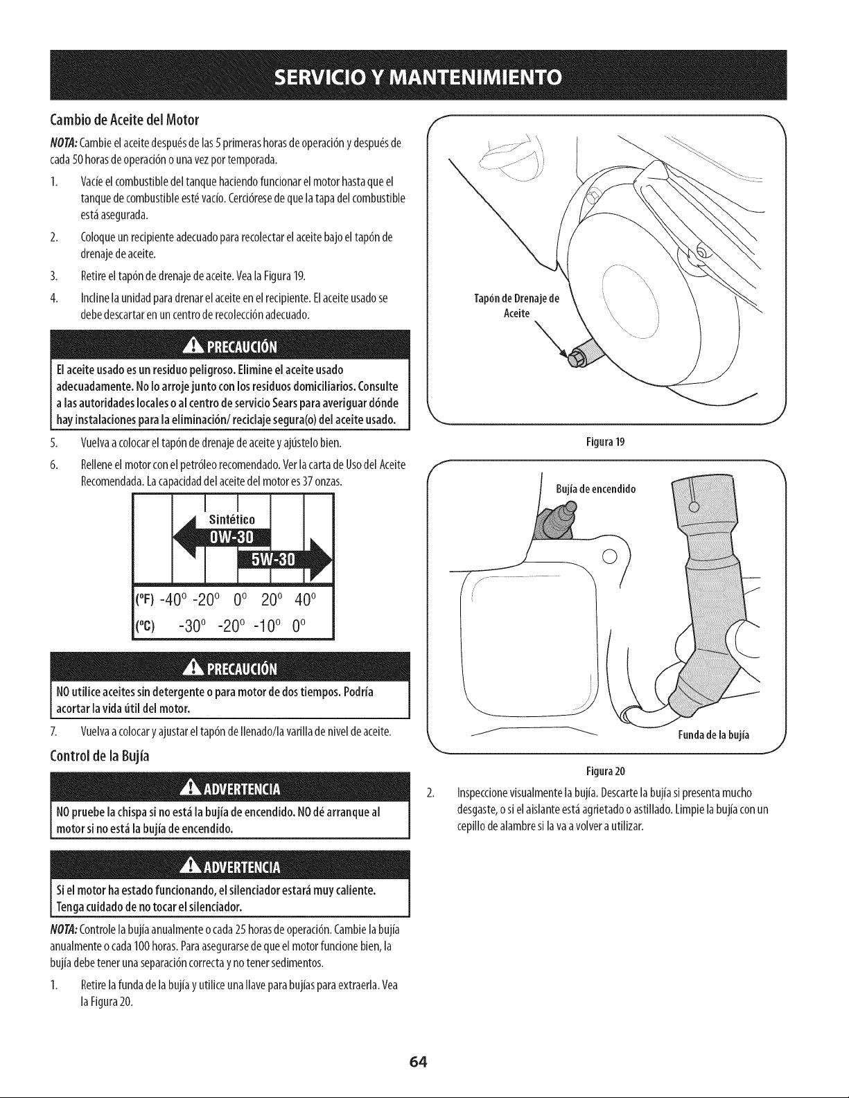
CambiodeAceitedel Motor
NOTA:Cambieelaceitedespu#sdelas5 primerashorasdeoperaci6nydespu#sde
cada50horasdeoperacidno unavezportemporada.
1. Vacieelcombustibledeltanquehaciendofundonarel motorhastaqueel
tanquede combustibleest#vac[o.Cerddresede quelatapadelcombustible
est_asegurada.
2. Coloqueunrecipienteadecuadopararecolectarelaceitebajoeltapdnde
drenajedeaceite.
3. Retireeltapdndedrenajedeaceite.VealaFigura19.
4. Inclinelaunidadparadrenarelaceiteenelrecipiente.Elaceiteusadose
debedescartaren uncentrode recoleccidnadecuado.
Elaceiteusadoesun residuopeiigroso.Elimineelaceite usado
adecuadamente.NoIoarrojejunto con losresiduosdomiciliarios.Consuite
a [asautoridadeslocalesoal centrode servicioSearsparaaveriguard6nde
hayinstaiacionesparala eiiminaci6n/recidaje segura(o)de[ aceite usado.
5,
6.
Vuelvaacolocareltap6ndedrenajedeaceitey ajustelobien.
Relleneel motorconel petrdleorecomendado.VerlacartadeUsodelAceite
Recomendada.Lacapacidaddelaceitedelmotores37onzas.
(°F)-40 °-20 ° 0 o 200 400
(oc) -300 -200 -10° 0°
NOutHiceaceitessindetergenteo paramotor dedostiempos.Podria
acortar lavida uti[ de[ motor.
7. Vuelvaacolocaryajustarel tap6ndeIlenado/lavarilladenivelde aceite.
Controlde la gujia
NOpruebeiachispasi noest,_ia bujia de encendido.NOd_ arranque ai
motorsi no est_la bujia de encendido.
f
f
Tap6nde Drenajede
Aceite
Figura19
Bujiade encendido
©
....... Fundade ia bujia
Figura20
Inspeccionevisualmentelabujia.Descartelabujiasi presentamucho
desgaste,o sielaislanteest_agrietadooastillado.Limpielabujiaconun
cepillodealambresi lava avolvera utilizar.
J
Siel motor haestado fundonando,el silendador estar,_muy caliente.
Tengacuidadodeno tocarel silendador.
NOTA:Controle{abujiaanualmenteocada25 horasdeoperacidn.Gamble{abujia
anualmenteocada100horas.Paraasegurarsede queelmotorfundonebien,la
bujiadebetenerunaseparaddncorrectay notenersedimentos.
I. Retirelafundadelabujiayutiliceunallaveparabujiasparaextraerla.Vea
laFigura20.
64
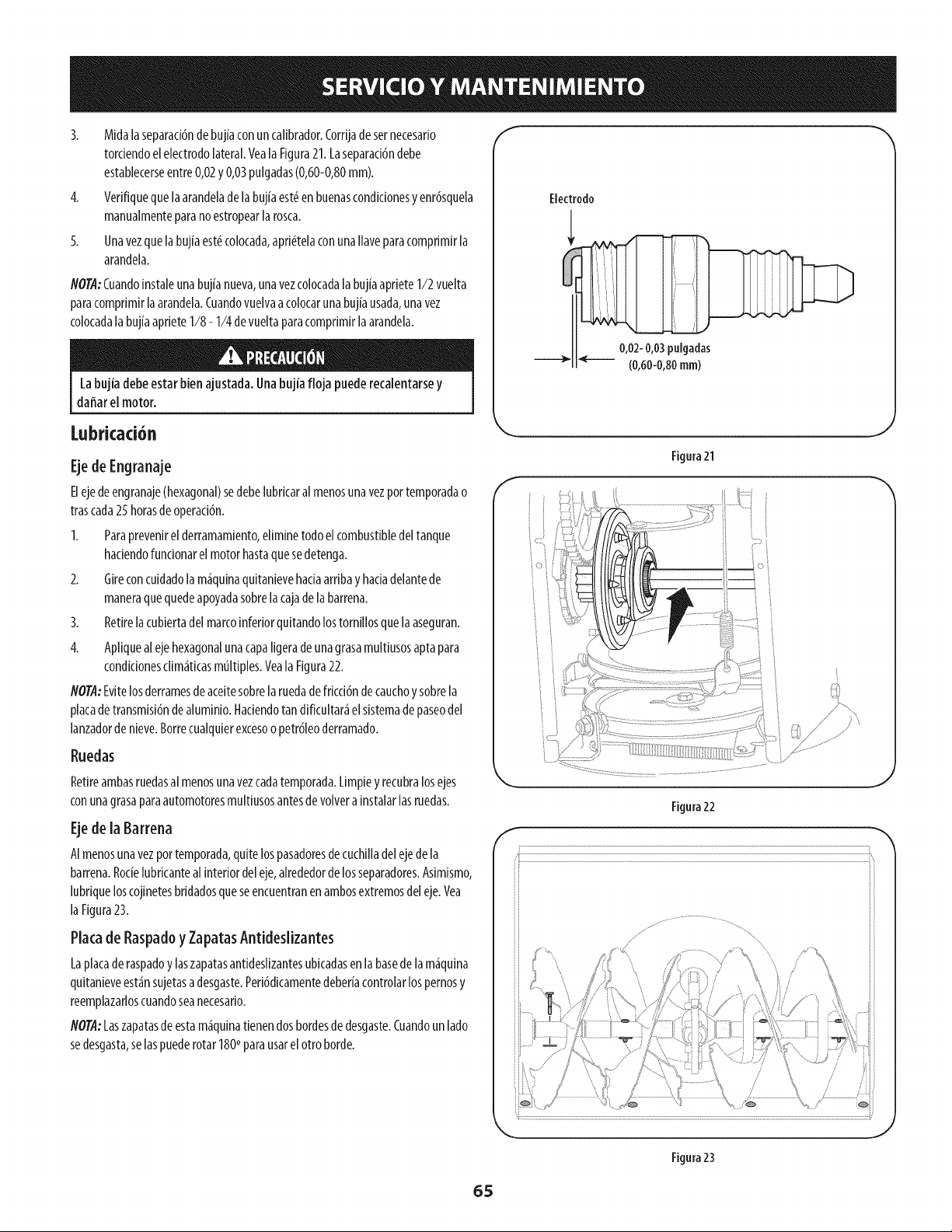
3. Midalaseparaci6ndebujiaconuncalibrador.Corrijade sernecesario
torciendoelelectrodolateral.Veala Figura21.Laseparaci6ndebe
establecerseentre0,02y 0,03pulgadas(0,60-0,80mm).
4. Verifiquequelaarandeladelabujiaest_en buenascondlclonesy enr6squela
manualmenteparanoestropearlarosca.
5. Unavezquelabujiaest_colocada,apri_telaconunallaveparacomprimirla
arandela.
NOTA:Cuandoinstaleunabujianueva,unavezcolocadalabujiaaprieteI/2 vuelta
paracomprimirlaarandela.Cuandovuelvaa colocarunabujiausada,unavez
colocadalabujiaaprieteI/8 - I/4 devueltaparacomprimirlaarandela.
Labujia debeestar bienajustada.Unabujia floja puederecalentarsey
daffarel motor.
f
Electrodo
0,02-0,03pulgadas
--_" _ (0,60-0,80ram)
Lubricaci6n
EjedeEngranaje
Elejedeengranaje(hexagonal)sedebelubricaralmenosunavezportemporadao
trascada25 horasdeoperaci6n.
I. Paraprevenlrel derramamlento,ellminetodoelcombustibledeltanque
haciendofuncionarelmotorhastaquesedetenga.
2. Glreconcuidadolam_quinaquitanievehaciaarribay hacladelantede
maneraquequedeapoyadasobrelacajadelabarrena.
3. Retirelacubiertadel marcoinferiorqultandolostornlllosquelaaseguran.
4. Apllquealejehexagonalunacapaligeradeunagrasamultiusosaptapara
condlclonescllm_ticasmultiples.Veala Flgura22.
NOTA:Evltelosderramesdeaceitesobrela ruedadefdccl6ndecauchoy sobrela
placadetransmisi6ndealumlnio.Haciendotandlficultar_elsistemade paseodel
lanzadorde nleve.Borrecualquierexcesoopetr61eoderramado.
Ruedas
Retireambasruedasal menosunavezcadatemporada.Limpiey recubralosejes
conunagrasaparaautomotoresmultiusosantesdevolverainstalarlasruedas.
Ejede la Barrena
AImenosunavezportemporada,quitelospasadoresdecuchilladelejedela
barrena.Rocielubricantealinteriordeleje,alrededorde losseparadores.Asimismo,
lubriqueloscojinetesbridadosqueseencuentranenambosextremosdeleje.Vea
laFigura23.
Plata de RaspadoyZapatasAntideslizantes
Laplacaderaspadoy laszapatasantideslizantesubicadasenlabasedelam_quina
quitanieveest_nsujetasadesgaste.Peri6dicamentedeberiacontrolarlospernosy
reemplazarloscuandoseanecesario.
NOT.4:Laszapatasdeestam_quinatienendosbordesde desgaste.Cuandounlado
sedesgasta,selaspuederotar1800parausarelotto borde.
Figura21
J
Figura22
f
Figura23
65
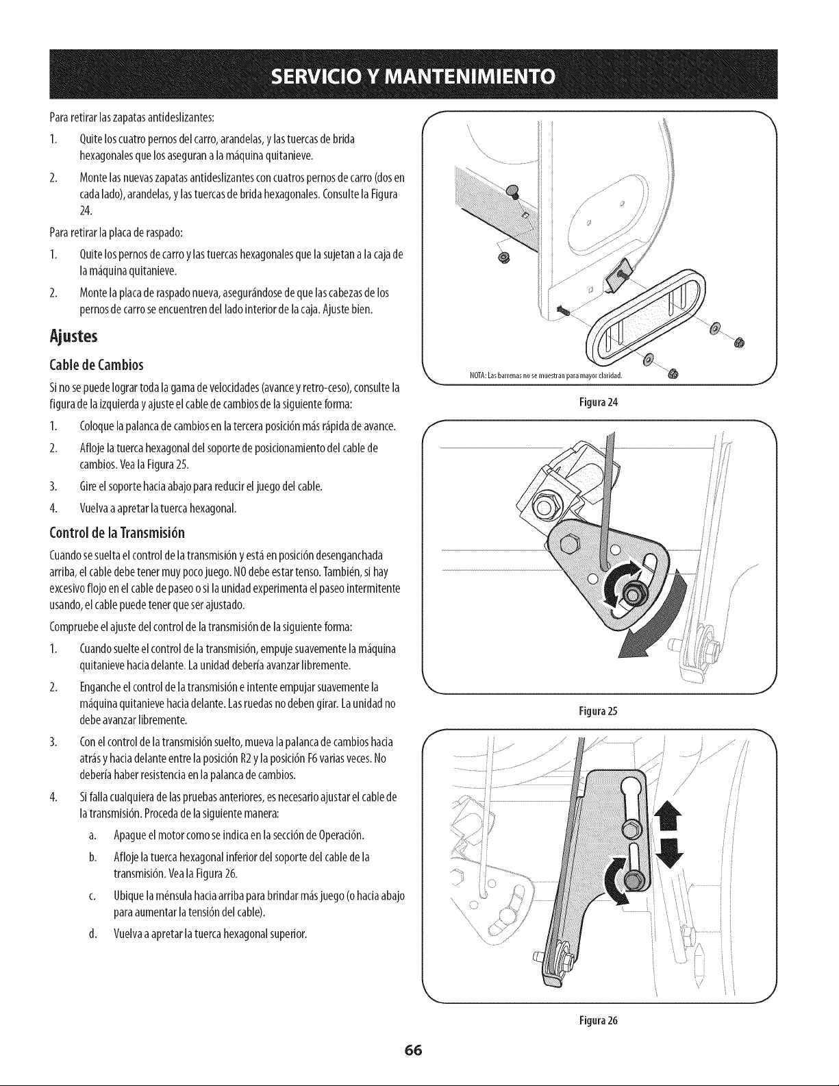
Pararetirarlaszapatasantideslizantes:
1. Quiteloscuatropernosdelcarro,arandelas,ylastuercasdebrida
hexagonalesquelosaseguranala m_quinaquitanieve.
2. Montelasnuevaszapatasantideslizantesconcuatrospernosdecarro(dosen
cadalado),arandelas,y lastuercasdebridahexagonales.ConsultelaFigura
24.
Pararetirarlaplacade raspado:
I. Quitelospernosdecarroy lastuercashexagonalesquelasujetanalacajade
lam_quinaquitanieve.
2. Montelaplacade raspadonueva,asegur_ndosedequelascabezasde los
pernosde carroseencuentrendel ladointeriordelacaja.Ajustebien.
CabledeCambios
Sinosepuedelogrartodala gamade veloddades(avaricey retro-ceso),consultela
figurade la[zquierdayajusteelcabledecambiosdelasiguienteforma:
I. Coloquela palancadecambiosenlaterceraposici6nm_sr_pidadeavarice.
2. Aflojelatuercahexagonaldelsoportede posidonamientodel cablede
cambios.VealaFigura25.
3. Gireelsoportehadaabajopararedudreljuegodelcable.
4. Vuelvaaapretarla tuercahexagonal.
Control de la Transmisi6n
Cuandosesueltaelcontroldelatransmisi6ny est_enposici6ndesenganchada
arriba,elcabledebetenetmuypocojuego.NOdebeestartenso.Tambidn,si hay
excesivoflojo enelcablede paseoo silaunidadexperimentaelpaseointermitente
usando,el cablepuedetenetquesetajustado.
Compruebeel ajustedelcontrolde latransmisi6ndelasiguienteforma:
1. Cuandosuelteelcontrolde latransmisi6n,empujesuavementelam_quina
quitanievehadadelante.Launidaddeberiaavanzarlibremente.
2. Engancheelcontrolde latransmisi6ne intenteempujarsuavementela
m_quinaquitanievehadadelante.Lasruedasno debengirar.Launidadno
debeavanzarlibremente.
4.
Conelcontroldelatransmisi6nsuelto,muevalapalancadecambioshacia
arrasy hadadelanteentrelaposici6nR2ylaposid6nF6variasveces.No
deberiahaberresistenciaenlapalancadecambios.
Sifallacualquieradelaspruebasanteriores,esnecesarioajustarelcablede
latransmisi6n.Procedade la siguientemanera:
a. Apagueelmotorcomoseindicaenlasecd6nde Operad6n.
b. Aflojelatuercahexagonalinferiordelsoportedel cabledela
transmisi6n.Veala Figura26.
c. Ubiquelamdnsulahaciaarribaparabrindarm_sjuego(ohaciaabajo
paraaumentarlatensi6ndelcable).
d. Vuelvaaapretarlatuercahexagonalsuperior.
f
NOTA:Lasbarrenasnose muestran paramayorclaridad.
Figura24
f
_f
f
Figura 25
.................
J
Figura26
66
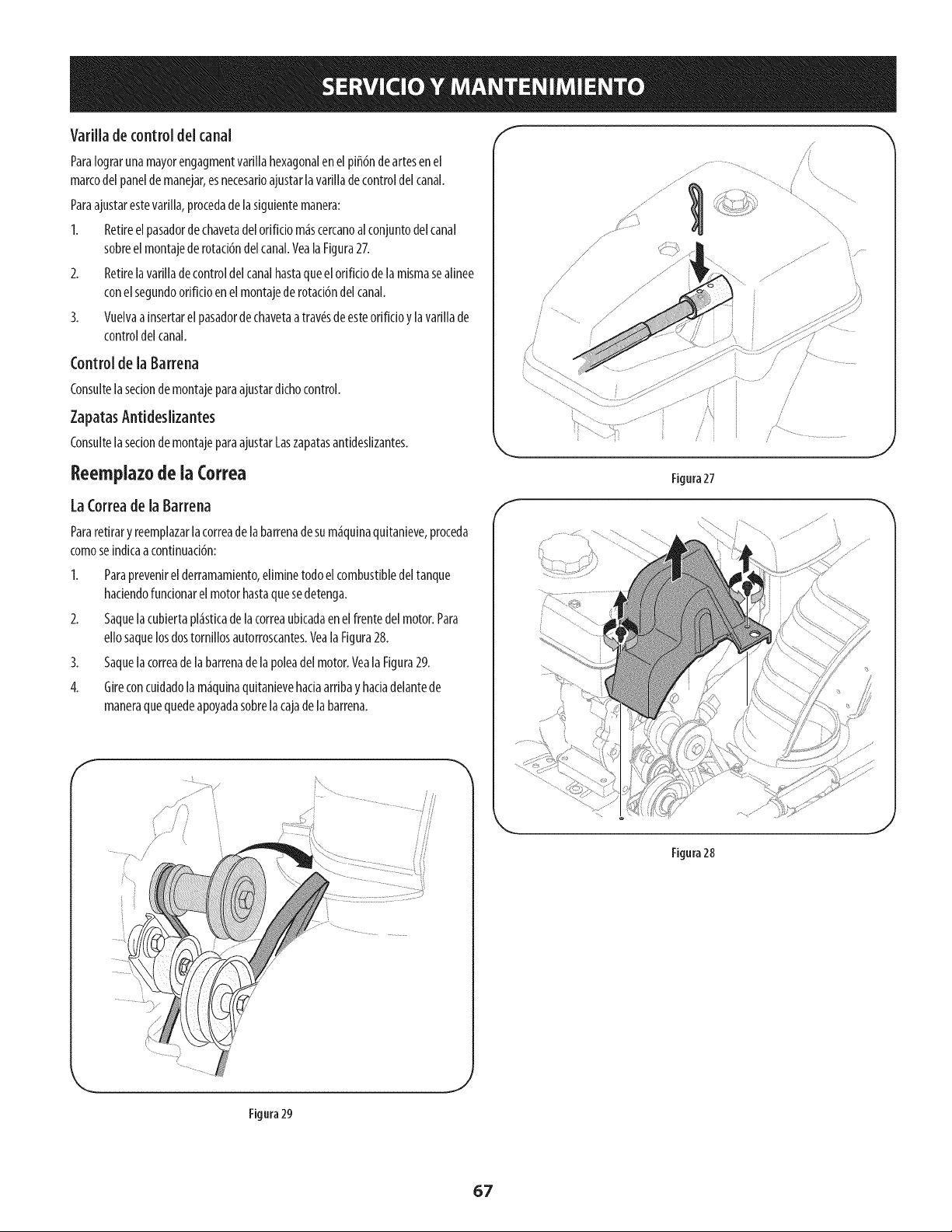
Varillade controldel canal
Paralograrunamayorengagmentvarillahexagonalenelpiff6ndeariesenel
marcodelpaneldemanejar,esnecesarioajustarlavarillade controldelcanal.
Paraajustarestevarilla,procedade lasiguientemanera:
I. Retireelpasadorde chavetadelorificio m4scercanoal conjuntodelcanal
sobreel montajede rotaci6ndel canal.VealaFigura27.
2. Retirelavariilade controldelcanalhastaqueelorificiodeiamismasealinee
conelsegundoorificioenel montajederotaci6ndelcanal.
3. Vuelvaa insertarelpasadordechavetaatrav_sdeesteorificioy lavarillade
controldel canal.
Control de la Barrena
Consultelasecionde montajeparaajustardichocontrol.
ZapatasAntideslizantes
Consultelasecionde montajeparaajustarLaszapatasantideslizantes.
Reemplazode la Correa
LaCorreade la Barrena
Pararetirary reemplazarla correadelabarrenadesum_quinaquitanieve,proceda
comoseindicaacontinuaci6n:
I. Paraprevenirel derramamiento,eliminetodoelcombustibledeltanque
haciendofuncionarelmotorhastaquesedetenga.
2. Saquelacubiertapl_sticade lacorreaubicadaen elfrentedel motor.Para
ellosaquelosdostornillosautorroscantes.VealaFigura28.
3. Saquelacorreade labarrenade lapoleadel motor.VealaFigura29.
4. Gireconcuidadolam_quinaquitanievehaciaarribay haciadelantede
maneraquequedeapoyadasobrelacajadelabarrena.
Figura27
Figura28
Figura29
.J
67
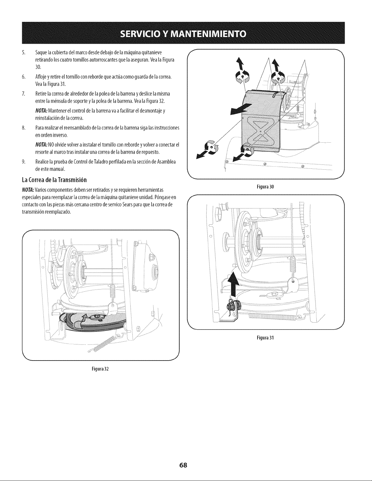
6.
8.
9.
5aquelacubiertadelmarcodesdedebajode lam_quinaquitanieve
retirandoloscuatrotornillosautorroscantesquelaaseguran.VealaFigura
30.
Aflojey retireeltornilloconrebordequeactuacomoguardadelacorrea.
VealaFigura31.
Retirelacorreadealrededorde lapoleade labarrenay deslicelamisma
entrelam6nsuladesoportey lapoleade labarrena.Veala Figura32.
NO@:Mantenerelcontrolde labarrenavaafacilitarel desmontajey
reinstalaci6nde lacorrea.
Pararealizarelreensambladodelacorreadelabarrenasigalasinstrucdones
enordeninverso.
NOTA"NOolvidevolverainstalareltornilloconrebordey volveraconectarel
resorteal marcotrasinstalarunacorreadelabarrenaderepuesto.
Realicela pruebadeControldeTaladroperfiladaen lasecci6ndeAsamblea
deestemanual.
LaCorreadela Transmisi6n
NOTA:Varioscomponentesdebenserretiradosyserequierenherramientas
espedalesparareemplazarlacorreade[am_quinaquitanieveunidad.P6ngaseen
contactoconlaspiezasm_scercanacentrodeservicoSearsparaquelacorreade
transmisi6nreemplazado.
i •
/
f
@
Figura30
J
Figura31
J
Figura32
.J
68
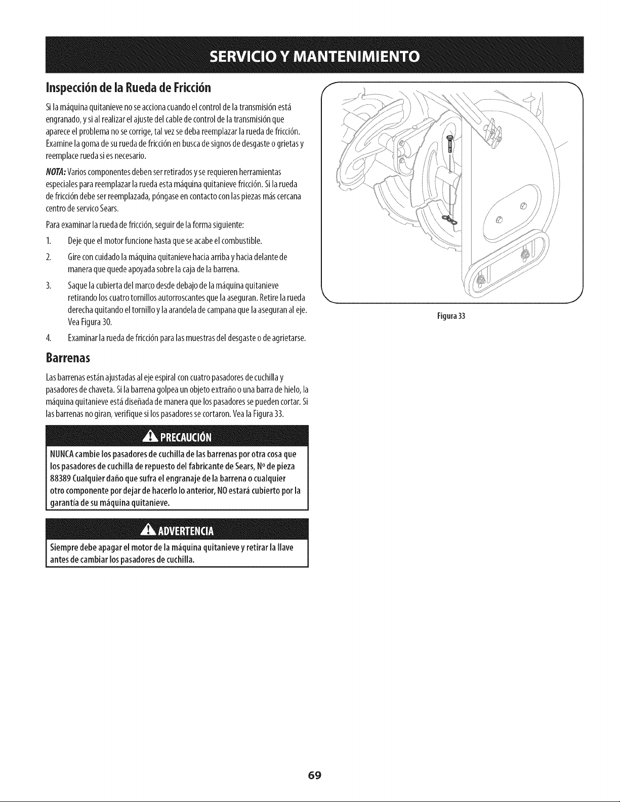
Inspecci6nde ia Ruedade Fricci6n
Sllam_quinaquitanievenoseacdonacuandoel controldelatransmisi6nest_
engranado,y sialrealizarel ajustedelcablede controldelatransmisi6nque
apareceelproblemanosecorrige,tal vezsedebareemplazar[aruedadefricd6n.
Examine[agomade suruedadefricd6nenbuscadesignosdedesgasteogrietasy
reemplaceruedasiesnecesario.
flO@-Varioscomponentesdebenserretiradosy serequierenherramientas
espedalesparareemplazar[aruedaestam_quinaquitanievefricci6n.Silarueda
defricci6ndebeserreemplazada,p6ngaseencontactoconlaspiezasm_scercana
centrodeservicoSears.
Paraexaminarlaruedade fricci6n,seguirdela formasiguiente:
1. Dejequeel motorfundonehastaqueseacabeelcombustible.
2. Gireconcuidadolam_quinaquitanievehadaarribay hadadelantede
maneraquequedeapoyadasobrelacajadelabarrena.
3. Saquelacubiertadelmarcodesdedebajode lam_quinaquitanieve
retirandoloscuatrotornillosautorroscantesquelaaseguran.Retirelarueda
derechaquitandoeltornilloy laarandeladecampanaquelaaseguranaleje.
VeaFigura30.
4. Examinarla ruedadefricd6nparalasmuestrasdel desgasteodeagrietarse.
Figura33
/
\\
Barrenas
Lasbarrenasest_najustadasal ejeespiralconcuatropasadoresdecuchillay
pasadoresdechaveta.Sila barrenagolpeaunobjetoextraffoo unabarradehielo,la
m_quinaquitanieveest_diseffadade maneraquelospasadoressepuedencortar.Si
lasbarrenasnogiran,verifiquesilospasadoressecortaron.YealaFigura33.
NUNCAcambielospasadoresde cuchiiiade [asbarrenaspor otra cosaque
lospasadoresde cuchiilade repuestode[fabricante de Sears,Node pieza
88389Cualquierdaffoquesufra el engranajede [a barrenaocuaiquier
otrocomponentepordejar de hacer[o1oanterior, NOestar_cubierto por[a
garant[ade sum_quina quitanieve.
Siempredebe apagare[ motorde [am_quinaquitanievey retirar [a Have
antesde cambiarlospasadoresde cuchilla.
69
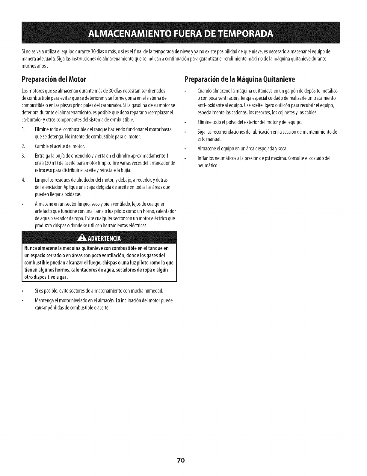
Sinosevaa uti[izaelequipodurante30d{aso m_s,o sieselfinal de[atemporadadenievey yano existeposibilidaddequenieve,esnecesarioalmacenarelequipode
maneraadecuada.Siga[asinstrucdonesde a[macenamientoqueseindicanacontinuaddnparagarantizare[rendimientom_ximode [am_quinaquitanievedurante
muchosafros.
Preparad6ndelMotor
Losmotoresquesealmacenandurantem_sde30diasnecesitanserdrenados
decombustibleparaevitarquesedeteriorenyseformegomaenelsistemade
combustibleoenlaspiezasprindpaiesdelcarburador.S[lagasolinadesumotorse
deterioraduranteelalmacenamiento,esposiblequedebarepararoreemplazarel
carburadory otroscomponentesdel sistemadecombustible.
1. Eliminetodoelcombustibledeltanquehadendofundonarelmotorhasta
quesedetenga.No[ntentedecombustibleparaelmotor.
2. Cambieelaceitedelmotor.
3. Extraigalabujiadeencendidoy viertaeneldlindro aproximadamente1
onza(30ml)deaceiteparamotorlimpio.Tirevariasvecesdelarrancadorde
retrocesoparadistribuirel aceiteyreinstalela bujia.
4. Limpielosresiduosdealrededordelmotor,ydebajo,alrededor,y detr_s
delsilendador.Apiiqueunacapadelgadadeaceiteentodaslas_reasque
puedenIlegaraoxidarse.
Almaceneenun sectorlimp[o,secoy bienventilado,lejosdecuaiquier
artefactoquefundoneconunallamao luzpilotocomounhomo,calentador
deaguaosecadorderopa.Evitecualquiersectorconunmotorel#ctricoque
produzcacHspasodondeseutilicenherramientasel#ctricas.
e
Nuncaalmacenela m_quinaquitanieveconcombustibleen eltanque en
un espadocerradoo en _reascon pocaventiiad6n, donde losgasesde[
combustible puedanakanzar elfuego, chispasouna luzpiloto comola que
tienen algunoshornos,calentadoresde agua,secadoresde ropaoalgun
otro disposffivoagas.
Preparad6nde ia M quina Quitanieve
Cuandoalmacenelam_qulnaqultanleveen ungalp6ndedep6sitomet_lico
o conpocaventilaci6n,tengaespecialcuidadoderealizarleuntratamiento
anti- oxidanteal equipo.UseaceiteIigeroosilic6npararecubrirel equipo,
espedalmentelascadenas,losresortes,loscojinetesy loscables.
Eliminetodoelpolvodelexteriordelmotory delequipo.
Sigalasrecomendadonesdelubricaci6nenlasecci6nde mantenimientode
estemanual.
Almaceneelequipoen un_readespejadayseca.
Inflarlosneum_ticosa lapresi6nde psim_xlma.Consulteelcostadodel
neum_tico.
Siesposible,evitesectoresdealmacenamientoconmuchahumedad.
Mantengaelmotorniveiadoenelaimac_n.Lainclinad6ndel motorpuede
causarp_rdidasdecombustibleoaceite.
70
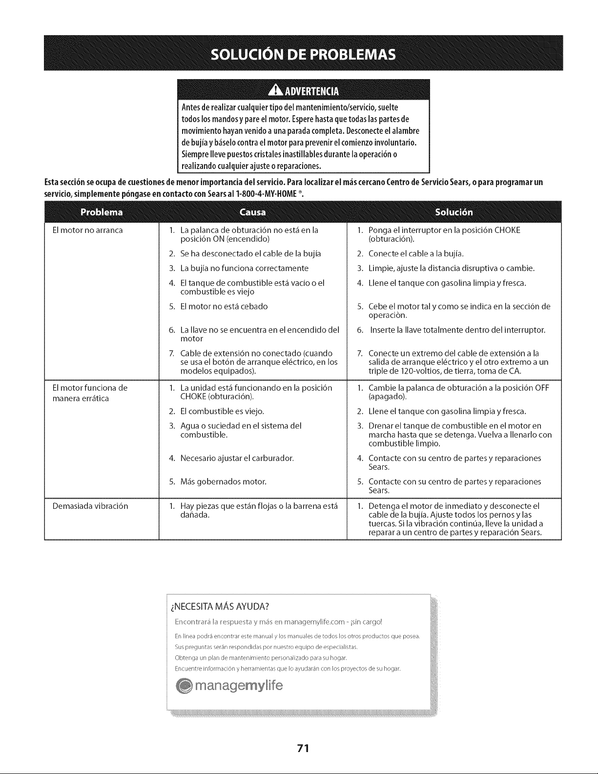
Antesde realizarcualquiertipo del mantenimiento/servicio,suelte
todoslosmandosy pare el motor. Esperehastaquetodas laspartesde
movimiento hayanvenidoa unaparadacompleta.Desconecteel alambre
de bujia yb_selocontrael motor paraprevenir elcomienzoinvoluntario.
Siemprellevepuestoscristalesinastillablesdurante laoperaci6no
realizandocualquierajusteo reparaciones.
Estasecd6nseocupa de cuestionesde menor importanda del servido. ParaIocaiizarel m_scercanoCentro de Servkio Sears,o para programar un
servido,simplemente p6ngaseen contactocon Searsal 1-800-4-MY-HOME%
Elmotor no arranca I. La palanca de obturaci6n no est_ en la
Elmotor funciona de
manera err_tica
Demasiada vibraci6n
posici6n ON (encendido)
2. Se ha desconectado el cable de la bujia
3. La bujia no funciona correctamente
4. El tanque de combustible est_ vacio o el
combustible es viejo
5. El motor no est_ cebado
6. La llave no se encuentra en el encendido del
motor
7. Cable de extensi6n no conectado (cuando
se usa el bot6n de arranque el_ctrico, en los
modelos equipados).
1. La unidad est_fifuncionando en la posici6n
CHOKE (obturaci6n).
2. El combustible es viejo.
3. Agua o suciedad en el sistema del
combustible.
4. Necesario ajustarel carburador.
5. M_s gobernados motor.
1. Hay piezas que est_n flojas o la barrena est_
dahada.
1. Ponga el interruptor en la posici6n CHOKE
(obturaci6n).
2. Conecte el cable a la bujia.
3. Limpie, ajuste la distancia disruptiva o cambie.
4. Llene el tanque con gasolina limpia y fresca.
5. Cebe el motor tal y como se indica en la secci6n de
operaci6n.
6. Inserte la Ilave totalmente dentro del interruptor.
1.
2.
3.
4.
5.
Conecte un extremo del cable de extensi6n a la
salida de arranque el_ctrico y el otro extremo a un
triple de 120-voltios, de tierra, toma de CA.
Cambie la palanca de obturaci6n a la posici6n OFF
(apagado).
Llene el tanque con gasolina limpia y fresca.
Drenar el tanque de combustible en el motor en
marcha hasta que se detenga. Vuelva a llenarlo con
combustible limpio.
Contacte con su centro de partes y reparaciones
Sears.
Contacte con su centro de partes y reparaciones
Sears.
1.
Detenga el motor de inmediato y desconecte el
cable de la bujia. Ajuste todos los pernos y las
tuercas. Si la vibracidn contin0a, lleve la unidad a
reparar a un centro de partes y reparacidn Sears.
71
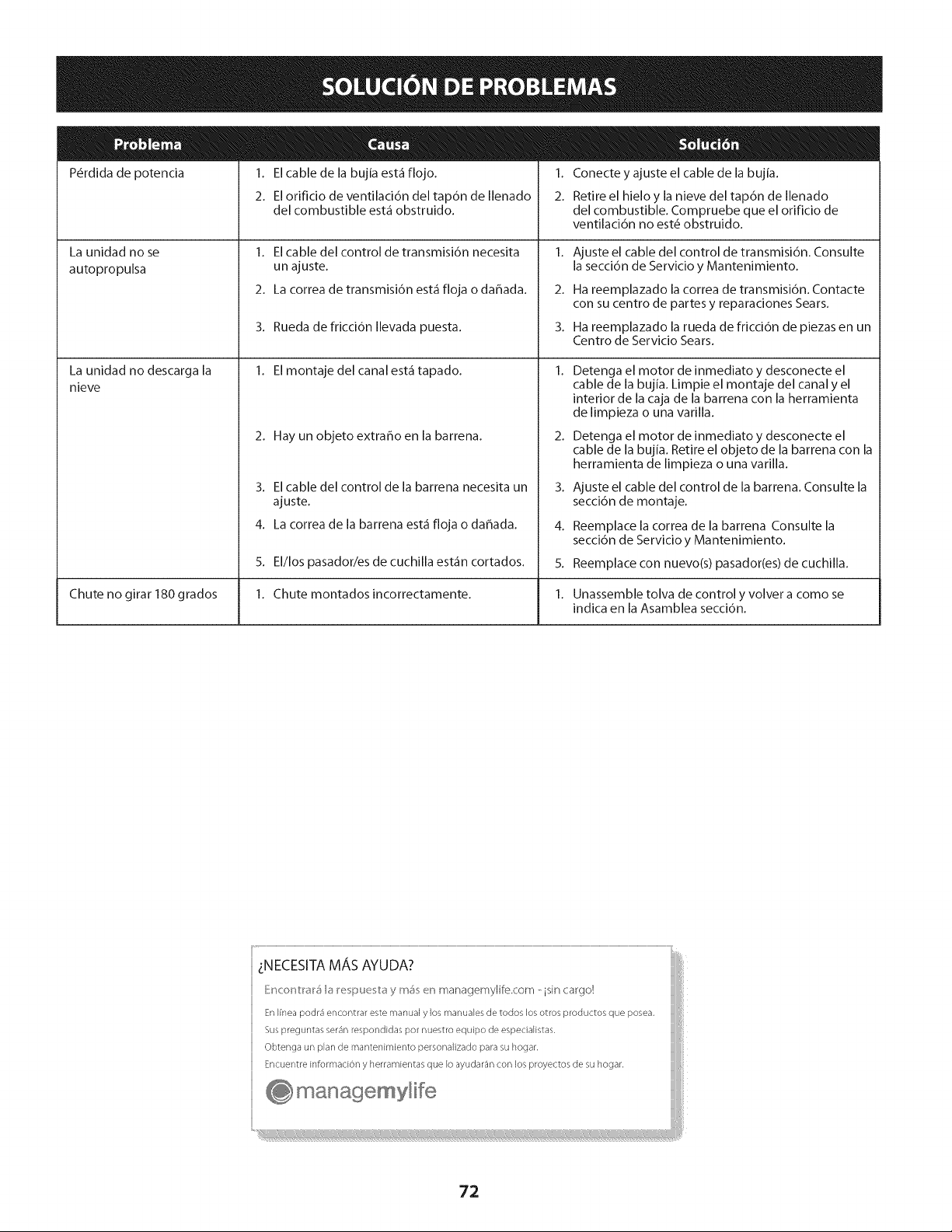
P@dida de potencia 1. El cable de la bujia est_ flojo.
2. El orificio de ventilaci6n del tap6n de Ilenado
del combustible est_ obstruido.
1. El cable del control de transmisi6n necesita
un ajuste.
2. La correa de transmisi6n est_ floja o dahada.
La unidad no se
autopropulsa
3. Rueda de fricci6n Ilevada puesta.
1. El montaje del canal est_ tapado.
2. Hay un objeto extraho en la barrena.
3. El cable del control de la barrena necesita un
ajuste.
4. La correa de la barrena est_ floja o dahada.
La unidad no descarga la
nieve
1. Conecte y ajuste el cable de la bujia.
2. Retire el hielo y la nieve del tap6n de Ilenado
del combustible. Compruebe que el orificio de
ventilaci6n no est_ obstruido.
1.
2.
3.
Ajuste el cable del control de transmisi6n. Consulte
la secci6n de Servicio y Mantenimiento.
Ha reemplazado la correa de transmisi6n. Contacte
con su centro de partes y reparaciones Sears.
Ha reemplazado la rueda de fricci6n de piezas en un
Centro de Servicio Sears.
2.
3.
4.
5.
Detenga el motor de inmediato y desconecte el
cable de la bujia. Limpie el montaje del canal y el
interior de la caja de la barrena con la herramienta
de limpieza o una varilla.
Detenga el motor de inmediato y desconecte el
cable de la bujia. Retire el objeto de la barrena con la
herramienta de limpieza o una varilla.
Ajuste el cable del control de la barrena. Consulte la
secci6n de montaje.
Reemplace la correa de la barrena Consulte la
secci6n de Servicio y Mantenimiento.
5. El/los pasador/es de cuchilla est_n cortados. Reemplace con nuevo(s) pasador(es) de cuchilla.
Chute no girar 180 grados 1. Chute montados incorrectamente. 1. Unassemble tolva de control y volver a como se
indica en la Asamblea secci6n.
_:NECESITA MA, S AYUDA?
Encont_#_5 b I_epue t# y m_ en managemylife.com - isin cargo!
En Ifnea podr_ encontrar este manual y los manuales de todos los otros p_oductos que pose&
Sus preguntas ser_n respondidas po_ nuestro equipo de espedalistas,
Obtenga un plan de mantenimiento personalizado para su hogar.
Encuentre information y herramientas que Io ayudar_n con los proyectos de su hogar.
managemylife
72
DECLARACI6NFEDERALy/o DECALiFORNiASOBREGARANTiASENELCONTROLDEEMISIONES
SUSDERECHOSY OBLIGACIONESENCUANTOA LAGARANTiA
MTD Consumer Group Inc, la Agencia de Proteccidn Medioambiental de los Estados Unidos (EPA), y para aquellos productos certificados para su
venta en el estado de California, el Departamento de los Recursos del Aire de California (CARB) se complacen en explicar la garantia que cubre
al sistema de control (ECS) de emisiones (evaporativas y/o de escape) de su equipo y motor (motor de equipos de exteriores) de encendido por
chispa para todo terreno, peque_o, de exteriores del a_o 2013 y ahos posteriores En California, los nuevos motores de equipos de exteriores
deben estar dise_ados, construidos y equipados para cumplir con las estrictas normas antipolucidn del Estado (en otros estados, los equipos
del aho 1997 y modelos posteriores deben ser estar dise_ados, construidos y equipados para cumplir con las regulaciones de motores de
encendido por chispa para todo terreno peque_os de la Agencia de Proteccidn Medioambiental de los Estados Unidos, (EPA). MTD Consumer
Group Inc. debe garantizar el sistema de control de emisiones (ECS) de su motor de equipos de exteriores por el periodo de tiempo indicado
m_is abajo, siempre y cuando no exista uso incorrecto, negligencia o mantenimiento inadecuado de dicho motor.
Su ECS puede incluir piezas tales como el carburador, el sistema de inyeccidn de combustible, el sistema de encendido, el convertidor catalitico,
los depdsitos de combustible, las lineas de combustible, los tapones de combustible, las wilvulas, contenedores, filtros, mangueras de vapor,
abrazaderas, conectores y otros componentes afines relacionados con las emisiones.
Donde exista una condicidn cubierta por la garantia, MTD Consumer Group Inc. reparar_i su motor de equipos de exteriores sin costo alguno
incluyendo el diagn6stico, las piezas y la mano de obra.
COBERTURADELA GARANTiADELFABRICANTE:
Este sistema de control de emisiones se garantiza por el t_rmino de dos a_os. Si alguna pieza relacionada con las emisiones de su motor de
equipos de exteriores es defectuosa, MTD CONSUMER GROUP INC. reparar_i o sustituir_i dicha pieza. En caso de que un componente est,1
cubierto pot m_is de dos ahos pot la garantia del equipo del fabricante, el periodo de cobertura ya no se aplicar_i.
RESPONSAI31LIDADESDELPROPIETARiOSEGUNLAGARANTiA:
En su car_icter de propietario del motor de equipos de exteriores, usted es responsable del mantenimiento requerido que se especifica en el
manual del propietario. MTD Consumer Group Inc le recomienda que conserve todos los recibos que cubren el mantenimiento de su motor, no
obstante Io cual MTD Consumer Group Inc no podr_i denegar el cumplimiento de la garantia 0nicamente pot la falta de los recibos.
Como propietario del motor de equipos de exteriores, usted debe saber que MTD Consumer Group Inc. puede denegar la cobertura de
la garantia si su motor o una pieza del mismo fallan debido a uso incorrecto, negligencia, mantenimiento indebido o a modificaciones no
aprobadas.
Usted es responsable de presentar su motor al centro de distribuci6n o servicio t_cnico de MTD Consumer Group Inc. tan pronto como
aparezca el problema. Las reparaciones cubiertas por la garantia se deben Ilevar a cabo en un lapso razonable que no exceda de 30 dias.
Si tiene alguna pregunta respecto de la cobertura de la garantia, p6ngase en contacto con el Departamento del Servicio T_cnico de MTD
Consumer Group Inc. al tel_fono 1-800-800-7310 o pot correo electr6nico en http://support.mtdproducts.com
COBERTURADELAGARANTiADEEMISIONESGENERALES:
MTD Consumer Group Inc garantiza al comprador final y a cada comprador subsiguiente que el motor de equipos de exteriores: est,1 dise_ado,
construido y equipado de modo de cumplir con todas las regulaciones aplicables y que se encuentra libre de defectos de materiales y de
fabricaci6n que pudieren causar la falla de una pieza garantizada id_ntica, en todos los aspectos materiales a la pieza descripta en la solicitud
de certificacidn de MTD Consumer Group Inc.
El periodo de garantia comienza en la fecha de entrega del motor al comprador final o en la fecha en que la m_iquina se pone en
funcionamiento pot primera vez. El periodo de garantia es de dos ahos.
Sujeto a ciertas condiciones y exclusiones que se indican a continuaci6n, la garantia de las piezas relacionadas con las emisiones es la siguiente:
1. Cualquier pieza garantizada que no est_ programada para set reemplazada como parte del mantenimiento requerido en las instrucciones
escritas suministradas se garantiza pot el periodo de garantia arriba mencionado. Si la pieza falla durante el periodo de cobertura de la
garantia, la misma ser_i reparada o reemplazada pot MTD Consumer Group Inc. de acuerdo con el p_irrafo (4) a continuaci6n. Cualquier
pieza reparada o reemplazada seg0n la garantia se garantizar_i por el resto del periodo de garantia.
2. Cualquier pieza garantizada que est_ programada solamente para inspecci6n regular en las instrucciones escritas suministradas se
garantiza pot el periodo de garantia arriba mencionado. Cualquier pieza reparada o reemplazada seg0n la garantia se garantizar_i pot el
resto del periodo.
3. Cualquier pieza garantizada que est_ programada para reemplazo seg0n el mantenimiento requerido de conformidad con las
instrucciones escritas suministradas, se garantiza pot el periodo de tiempo anterior a la primera fecha de reemplazo programada para esa
pieza. Si la pieza falla antes del primer reemplazo programado, la misma ser_i reparada o reemplazada pot MTD Consumer Group Inc. de
acuerdo con el p_irrafo (4) a continuaci6n. Cualquier pieza reparada o reemplazada bajo garantia se garantizar_i pot el resto del periodo
anterior al primer reemplazo programado puntual para esa pieza.
4. La reparaci6n o el reemplazo de cualquier pieza garantizada de conformidad con las disposiciones de la garantia que aqui se estipula se
deben realizar en un centro de garantia sin costo alguno para el propietario.
5. No obstante las disposiciones que aqui se estipulan, los servicios o reparaciones bajo garantia se suministrar_in en todos nuestros centros
de distribuci6n bajo franquicia de mantenimiento para los motores o equipos en cuesti6n.
6. Elpropietariodelmotordeequiposdeexterioresnodeber_pagareltrabajodediagndsticodirectamenteasociadoconunapieza
garantizadadefectuosaenrelaci6nconlasemisiones,siempreycuandodichotrabajodediagn6sticoserealiceenuncentrocubiertopot
lagarantia.
7. MTDConsumerGroupIncesresponsablepotdahoscausadosaotroscomponentesdemotoresoequiposderivadosdelafallabajo
garantiadecualquierpiezagarantizada.
8. Durantelatotalidaddelperiododegarantiadelmotoryequipoparatodoterrenoarribamencionado,MTDConsumerGroupInc
mantendr_unsuministro
depiezasbajogarantiasuficienteparasatisfacerlademandaesperadadetalespiezas.
9. Cualquierpiezadereemplazosepodr_usarparaelcumplimientodelmantenimientoolasreparacionesbajogarantiaysesuministraran
sincargopara
elpropietario.Dichousonoreducir_lasobligacionesdegarantiadeMTDConsumerGroupInc.
]0. Nosepodr_nusarpiezasadicionalesnimodificadasquenoest_nexentasdeacuerdoconelDepartamentodelosRecursosdelAire
(AirResourcesBoard).Elusodecualquierpiezaadicionalomodificadanoexentapotelcompradorfinalser_causaldeinvalidezdelos
reclamosbajogarantia.MTDConsumerGroupIncnotendr_responsabilidadpotlagarantiadefallasdepiezasgarantizadasquefueren
causadaspotelusodeunapiezaadicionalnoexenta
omodificada.
PI EZAS GARANTIZAi)AS:
La reparaci6n o el reemplazo de cualquier pieza garantizada que de otro modo pudiese estar cubierta por la garantia podr_ ser excluida de
tal cobertura de garantia si MTD Consumer Group Inc demuestra que el motor es objeto de uso incorrecto, negligencia o mantenimiento
inadecuado, y que tal uso incorrecto, negligencia o mantenimiento inadecuado rue causa directa de la necesidad de reparaci6n o reemplazo de
dicha pieza. No obstante Io antedicho, cualquier ajuste de un componente con un dispositivo de limitaci6n de ajuste instalado en f_brica y que
funcione adecuadamente, podr_ set cubierto pot la garantia. Adem_s,
la cobertura bajo esta garantia se extiende solo a piezas que estuvieron presentes en el motor y equipo todo terreno adquiridos.
Est_n cubiertas las siguientes piezas con garantia para emisiones (de corresponder):
1. Sistema de medici6n de combustible
Sistema de mejora para inicio en frfo (cebado suave)
Carburador y piezas internas (o sistema de inyecci6n pot combustible)
Bomba de combustible
Dep6sito de combustible
2. Sistema de inducci6n de aire
Purificador de aire
Colector de admisi6n
3. Sistema de encendido
Bujia(s) de encendido
Sistema de encendido pot magneto
4. Sistema de encendido
Convertidor catalitico
SAI (v_lvula Reed)
5. Componentes varios utilizados en el sistema anterior
Wlvulas e interruptores de vacio, temperatura, posici6n sensibles al tiempo
Conectores y montajes
6. Control evaporativo
Manguera de combustible
Abrazaderas de la manguera de combustible
Tap6n del combustible atado pot correa
Caja de carbono
Lineas de vapor
050790 Rev.A
Felicitacionespor haberrealizadouna adquisicidninteligente.EIproductoCraftsman®que ha adquiridoestddise#adoy fabricado
parabrindarmuchosa#osde funcionamientoconfiable.Perocomotodoslosproductosa vecespuederequerirde reparaciones.Es
en esemomento cuandoeldisponerde un Acuerdodeproteccidnpara reparacionesle puede ahorrardineroy problemas.
Acontinuad6nsedetailanlospuntosinduidosenel Acuerdo:
[] Servido experto prestadopornuestros10,000espedalistasenreparadonesprofesionales
[] Servido Uimitado sincargo paralaspiezasy la manodeobraentodaslasreparadonescubiertas
[] Reemplazodel producto hasta1500d6laressinoesposiblerepararel productocubierto
[] Descuentode 25%del predonormaldelservkioy delaspiezasreladonadasconel mismoquenoest_ncubiertaspor
el acuerdo;adem_s,25%delpredonormaldelavefificaci6ndemantenimientopreventivo
[] Ayudar_pidapot tei_fono- IoIlamamosResolud6nR_pida- el apoyotelef6nicodeun Chamuscaal representante.
Pienseennosotroscomoelmanual"deundueffohablador."
UnavezadquiridoelAcuerdo,puedeprogramarelservidocontan s61orealizarunaIlamadatelef6nica.PuedeIlamaren
cualquiermomentodeldfao dela nocheoprogramarunservk[oen Ifnea.
ElAcuerdodeProtecd6ndeReparad6nesunacomprasinfiesgo.Siustedanulaporalgunaraz6nduranteel peffodode
garantfadeproducto,propordonaremosunreembolsoIleno.O,unreembolsoprorrateadoencualquiermomentodespu_s
delpeffododegarantfadeproductoexpira,iAdquierahoysuacuerdodeprotecd6nparareparadones[
Seaplican determinadas iimitacionesy exclusiones.Para obtener informaci6nadicionai y preciosen los
EstadosUnidosiiameai 1-800-827-6655.
El*Coverageen Canad_variaen algunos artkulos. Paradetalles llenos la llamada ChamuscaCanad_en 1-800-
361-6665.
Servidode instalad6ndeSears
Sideseasolidtarla instalad6nprofesionaldeSearsdeaparatosdom_sticos,dispositivosparaabfirportones,calentadoresde
aguay otrosartkulosdom_sticosimportantes,enlosEstadosUnidoso Canad_Ilameal1-800-4-MY-HOME®.
75

Your Home
For troubleshooting, product manuals and expert advice:
managernylife
www.managemylife.com
For repair - in your home - of all major brand appliances,
lawn and garden equipment, or heating and cooling systems,
no matter who made it, no matter who sold it!
For the replacement parts, accessories and
owner's manuals that you need to do-it-yourself.
For Sears professional installation of home appliances
and items like garage door openers and water heaters.
1-800-4-MY-HOME ® (1-800-469-4663)
Call anytime, day or night (U.S.A. and Canada)
www.sears.com www.sears.ca
Our Home
For repair of carry-in items like vacuums, lawn equipment,
and electronics, call anytime for the location of your nearest
Sears Parts & Repair Service Center
1-800-488-1222 (U.S.A.) 1-800-469-4663 (Canada)
www.sears.com www.sears.ca
To purchase a protection agreement on a product serviced by Sears:
1-800-827-6655 (U.S.A.) 1-800-361-6665 (Canada)
Para pedir servicio de reparaci6n
a domicilio, y para ordenar piezas:
1-888-SU-HOGAR ®
(1-888-784-6427)
www.sears.com
Au Canada pour service en frangais:
1-800-LE-FOYER Mc
(1-800-533-6937)
www.sears.ca
® Registered Trademark / TMTrademark of KCD IP, LLC in the United States, or Sears Brands, LLC in other countries
® Marca Registrada ! TMMarca de Fabrica de KCD IP, LLC en Estados Unidos, o Sears Brands, LLC in otros paises
MCMarque de commerce ! MDMarque deposee de Sears Brands, LLC


