Loading ...
Loading ...
Loading ...
NOTE:Referencesto rightorleft sideof the snowthrowerare
determinedfromthe operatingpositionlookingforwardto the frontof
the machine.
REMOVING FROM CRATE
1. Removescrewsfromthe bottomof thecrate securingthesides,
andendsof the shippingcrate.
2. Lift off the topoff of the crate and set outof theway of the
assemblyarea.
3. Removeanddiscardplasticbagthatcoversunit.
4. Removeany loosepartsincludedwith unit (e.g.,Operator's
Manual,etc.).
5. Pushdownon the lowerhandleandpullunit backout of crate.
6. Makecertainthe crate has beencompletelyemptiedbefore
discardingit.
ASSEMBLY
1. Makecertainthe springsat the lowerend of the augerand drive
cablesaresecurelyhookedintotheir respectiveactuator
bracketsbeforepivotingthe handleupward.Referto Fig. 10.
a. Placethe speedselectorshiftleverin the F6 position.
b. Cut the cabletie securingthe two piecechute crank to the
lowerhandle.Thecable tie is usedfor shippingpurposes.
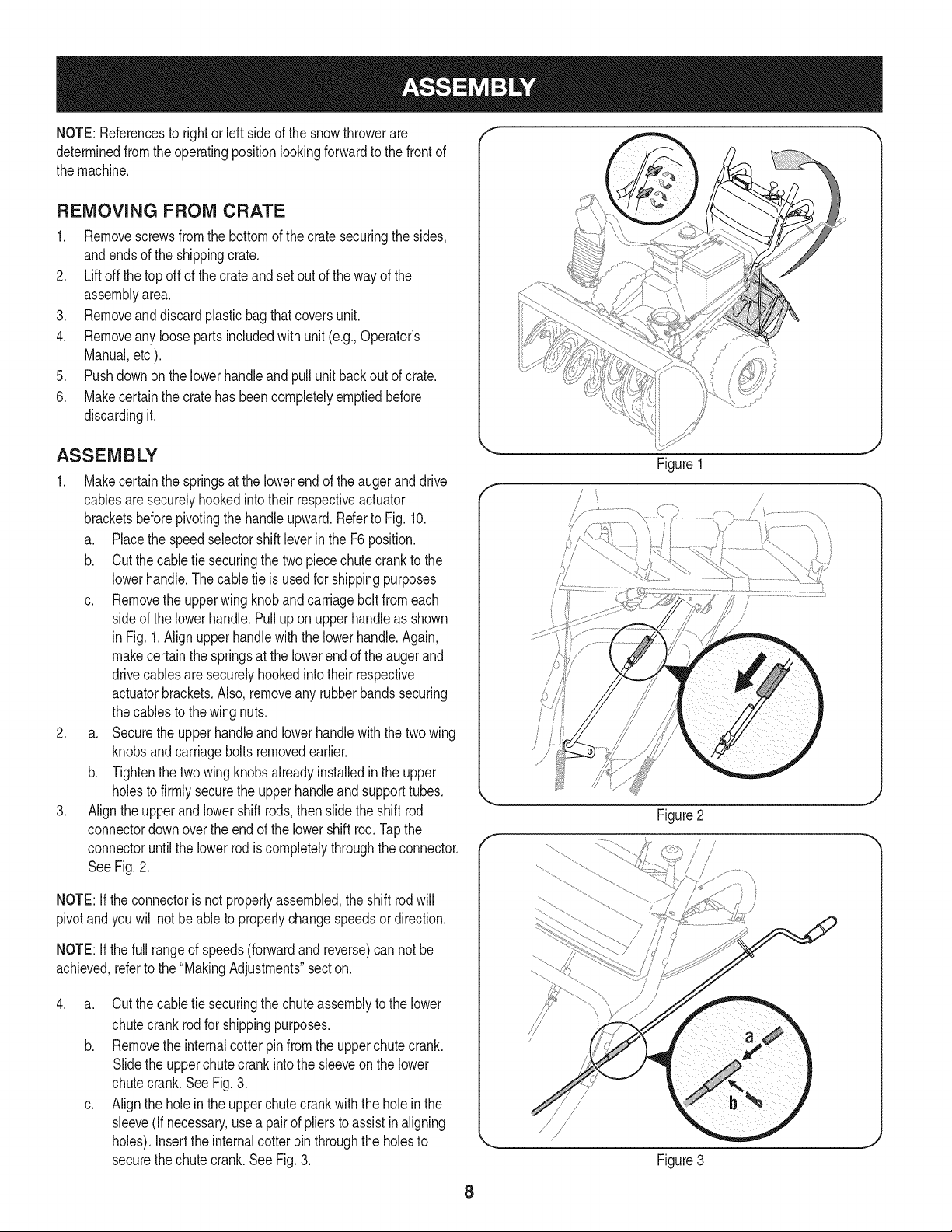
c. Removethe upperwingknobandcarriageboltfromeach
sideof the lowerhandle.Pulluponupperhandleas shown
in Fig. 1.Align upper handlewith the lowerhandle.Again,
makecertainthe springsat the lowerendof the augerand
drivecablesaresecurelyhookedintotheir respective
actuatorbrackets.Also,removeany rubberbandssecuring
thecablesto the wingnuts.
2. a. Securethe upperhandleandlowerhandlewiththetwo wing
knobsandcarriageboltsremovedearlier.
b. Tightenthetwo wingknobsalreadyinstalledin the upper
holesto firmlysecurethe upperhandleand supporttubes.
3. Align the upperand lowershift rods, thenslidethe shift rod
connectordownoverthe end of the lowershift rod.Tapthe
connectoruntilthe lower rodis completelythroughtheconnector.
See Fig.2.
NOTE:If theconnectoris notproperlyassembled,the shift rodwill
pivotand youwill notbe ableto properlychangespeedsor direction.
NOTE:If thefull rangeof speeds(forwardand reverse)can not be
achieved,referto the "MakingAdjustments"section.
.
a. Cut the cabletie securingthe chute assemblyto the lower
chutecrankrodfor shippingpurposes.
b. Removethe internalcotterpin from the upperchutecrank.
Slidethe upperchutecrankinto the sleeveon the lower
chutecrank.See Fig.3.
c. Alignthe holein the upperchutecrankwiththe holeinthe
sleeve(Ifnecessary,usea pairof pliersto assist in aligning
holes).Insertthe internalcotter pinthroughthe holesto
securethe chutecrank.SeeFig.3.
Y
Figure 1
/
J
Figure3
8
Loading ...
Loading ...
Loading ...