Loading ...
Loading ...
Loading ...
2. Positionthe new skid shoesand securewith the carriagebolts
andhex nuts.Makecertainthe skidshoesare adjustedto be
level.
Shave Plate
1. Removethehex nutsandcarriagebolts that securethe shave
plateto the bottomof the housing.
2. Removethe rearmost hexnutand carriagebolt securingthe back
of eachskidshoeto the sidesof the housing.Loosenthefour
remaininghexnuts securingthe skid shoes.
3. Slide theshaveplateout of the off-set slotat thebottomof the
housing,andfrombetweenthe skidshoesandside panelsof the
housing.
4. With the mountingholestowardthe back of the unit, slidethe new
shaveplateinto positionandsecurewiththe fastenersremoved
previously.
ADJUSTMENTS
Speed selector Rod
If thefull rangeof speeds(forwardand reverse)cannotbe achieved,
referto Figure20 to the leftandadjustthe speedselector rod as
follows:
1. Lookingunderneaththe handlepanel,notewhich of thethree
holesin the speedselectorleverthe ferruleis insertedinto. Also
notethe directionof insertion.Thenremovethe internalcotter pin
andflatwasherfromthe ferruleandwithdrawthe ferrulefromthe
speedselector lever.SeeFigure23.
\ \
\
Ferrule
\ \
Figure23
2. Placespeedselector leverin sixth(6) positionor fastestforward
speed.
3. Pushspeedselector rodand speedselector armassemblydown
sharplyas faras itwill goto putthe driveintothe fastestforward
position.
4. As necessary,rotatethe ferruleupordownthe speedselector
roduntilthe ferrulelinesup with the holefrom which itwas earlier
removed.See Figure23.
5. Fromthedirectionnotedearlier,inserttheferruleintothe properhole.
6. Reinstallthe washerandthe internalcotter pin.
Chute Control
The distancesnow is throwncanbe adjustedbyadjustingthe angleof
the chuteassembly.Referto the Operationsectionfor instructions.
The remotechutecontrolcableshavebeen pre-adjustedat the factory.
Movethe remotechuteleveron the controlpanelforwardto pivotthe
upperchutedown;movethe leverrearwardto pivotthe upperchute
up.
Wheel drive control
Referto theAdjustmentsectionof theAssemblyinstructionsto adjust
the wheeldrivecontrol.Tofurther checkthe adjustment,proceedas
follows:
1. With the snowthrowertippedforward(becertainto runthe
fuel tankdry beforetippingthe unitforward),removethe frame
coverunderneaththe snowthrowerby removingthe self-tapping
screws.
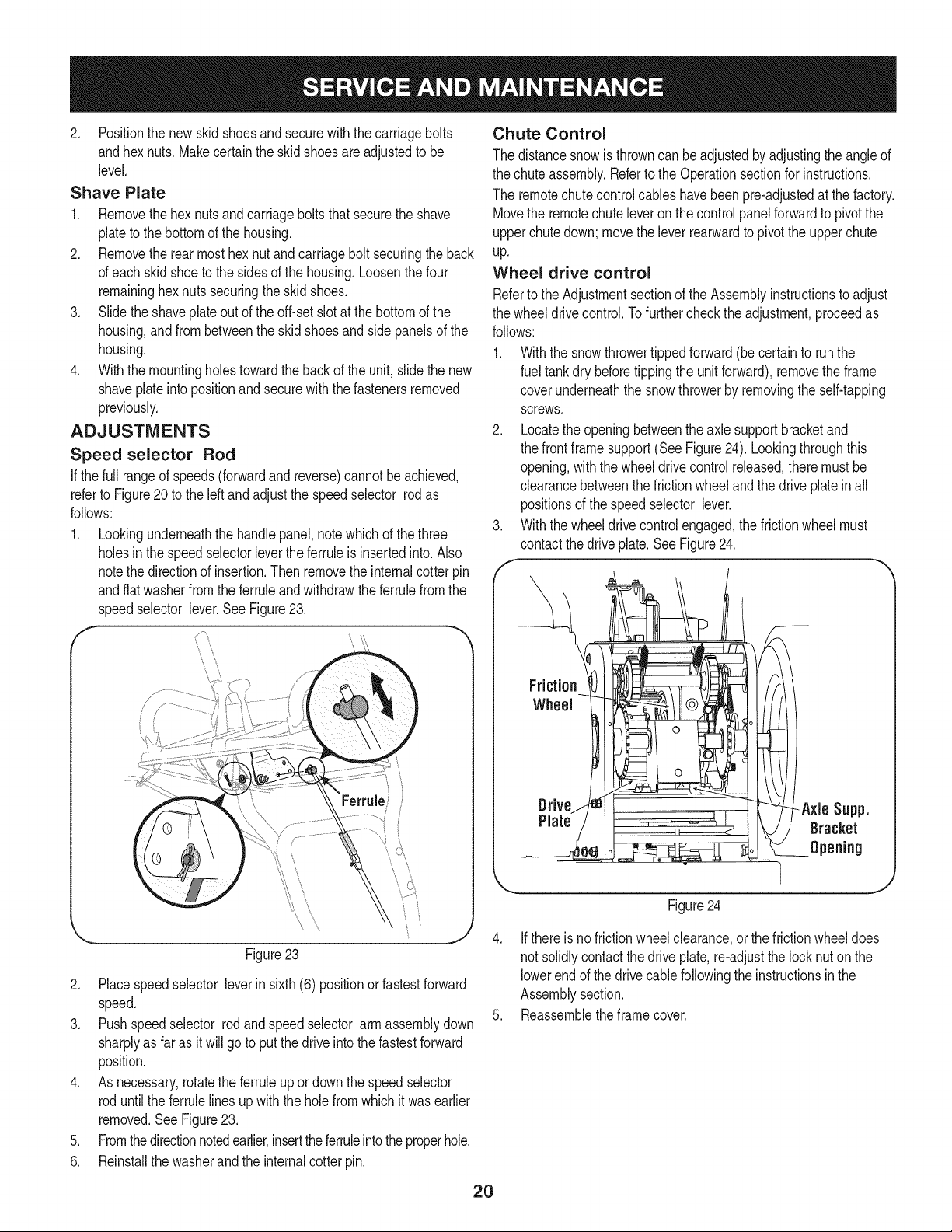
2. Locatethe openingbetweenthe axle supportbracketand
the frontframesupport(See Figure24). Lookingthroughthis
opening,with the wheeldrivecontrol released,there mustbe
clearancebetweenthe frictionwheelandthe drive plateinall
positionsof the speedselector lever.
3. With the wheeldrivecontrolengaged,the frictionwheel must
contactthe driveplate.SeeFigure24.
Friction
Wheel
Figure24
4. Ifthereis nofrictionwheelclearance,or thefrictionwheeldoes
notsolidlycontactthe drive plate,re-adjustthe locknut onthe
lowerend of the drivecablefollowingthe instructionsinthe
Assemblysection.
5. Reassembletheframecover.
2O
Loading ...
Loading ...
Loading ...