Loading ...
Loading ...
Loading ...
If your boiler is part of a planned heating system,
locate it where shown on your plan. If boiler isto
be part of an existing system, it is usually best to
put itwhere the old one was. !f you plan to change
location, you will need additional materials as well
as an adequate base. The following rules apply:
1. The boiler must be level. Metal shims may be
used under base legs for final leveling.
2. Use a raised base iffloor can become wet or damp.
3. The vent pipe connection should be as short
as possible.
4. Additional clearances for service may exceed
clearances for fire protection. Always comply
with the minimum fire protection clearances
shown on the boiler.An 18 inch clearance should
be maintained on any side where passage is
required to access another side for cleaning,
servicing, inspection or replacement of any part
that may need attention. An 18 inch clearance is
recommended on the control side for servicing.
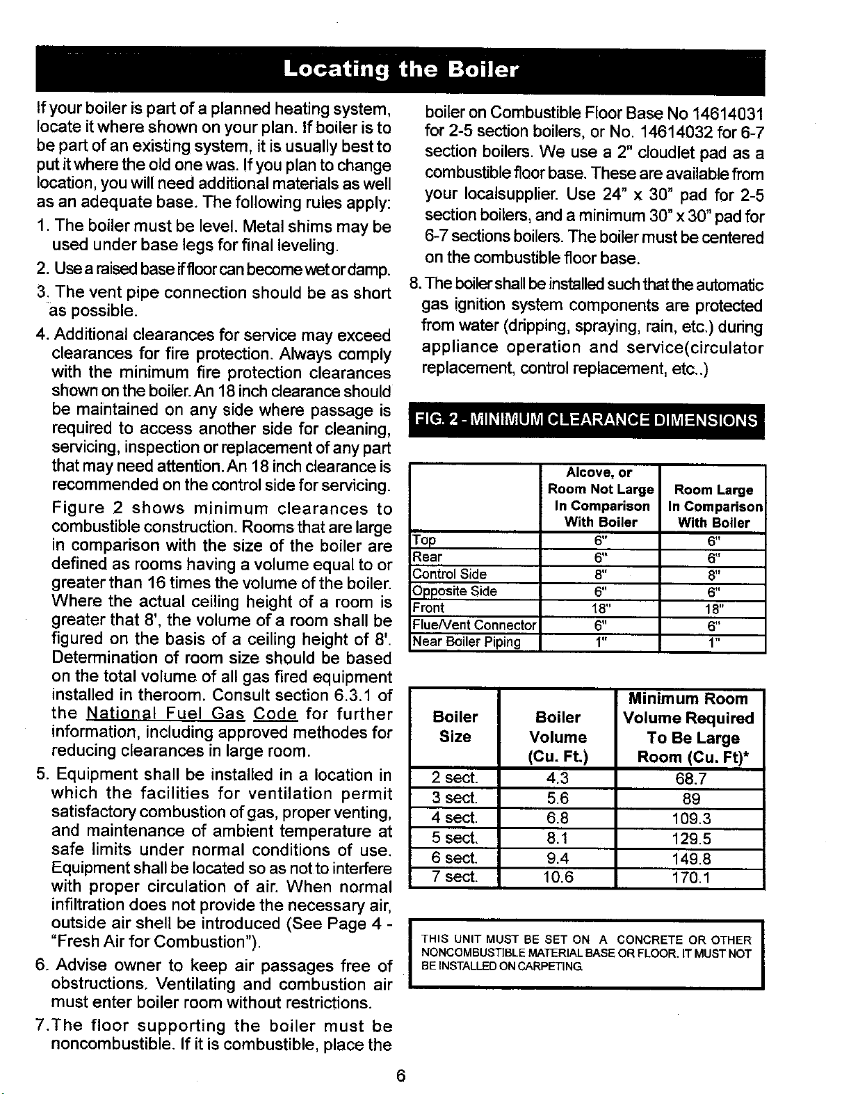
Figure 2 shows minimum clearances to
combustible construction. Rooms that are large
in comparison with the size of the boiler are
defined as rooms having a volume equal to or
greater than 16 times the volume of the boiler.
Where the actual ceiling height of a room is
greater that 8', the volume of a room shall be
figured on the basis of a ceiling height of 8'.
Determination of room size should be based
on the total volume of all gas fired equipment
installed in theroom. Consult section 6.3.1 of
the National Fuel Gas Code for further
information, including approved methodes for
reducing clearances in large room.
5. Equipment shall be installed in a location in
which the facilities for ventilation permit
satisfactory combustion of gas, proper venting,
and maintenance of ambient temperature at
safe limits under normal conditions of use.
Equipment shall be located so as not to interfere
with proper circulation of air. When normal
infiltration does not provide the necessary air,
outside air shell be introduced (See Page 4 -
"Fresh Air for Combustion").
6. Advise owner to keep air passages free of
obstructions. Ventilating and combustion air
must enter boiler room without restrictions.
7.The floor supporting the boiler must be
noncombustible. If it is combustible, place the
boiler on Combustible Floor Base No 14614031
for 2-5 section boilers, or No. 14614032 for 6-7
section boilers. We use a 2" cloudlet pad as a
combustible floor base. These are available from
your Iocalsupplier. Use 24" x 30" pad for 2-5
section boilers, and a minimum 30" x 30" pad for
6-7 sections boilers. The boiler must be centered
on the combustible floor base.
8.The boiler shall be installed such that the automatic
gas ignition system components are protected
from water (dripping, spraying, rain, etc.) during
appliance operation and service(circulator
replacement, control replacement, etc..)
Alcove, or
Room Not Large Room Large
In Comparison In Comparison
With Boiler With Boiler
Top 6" 6"
Rear 6" 6"
Control Side 8" 8"
Opposite Side 6" 6"
Front 18" 18"
FlueNent Connector 6" 6"
Near Boiler Piping 1" 1"
Minimum Room
Boiler Boiler Volume Required
Size Volume To Be Large
(Cu. Ft.) Room (Cu. Ft)*
2 sect. 4.3 68.7
3 sect. 5.6 89
4 sect. 6.8 109.3
5 sect. 8.1 129.5
6 sect. 9.4 149.8
7 sect. 10.6 170.1
I
THIS UNIT MUST BE SET ON A CONCRETE OR OTHER
NONCOMBUSTIBLE MATERIAL BASE OR FLOOR. IT MUST NOT
BE INSTALLED ON CARPETING
I
6
Loading ...
Loading ...
Loading ...