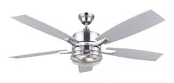
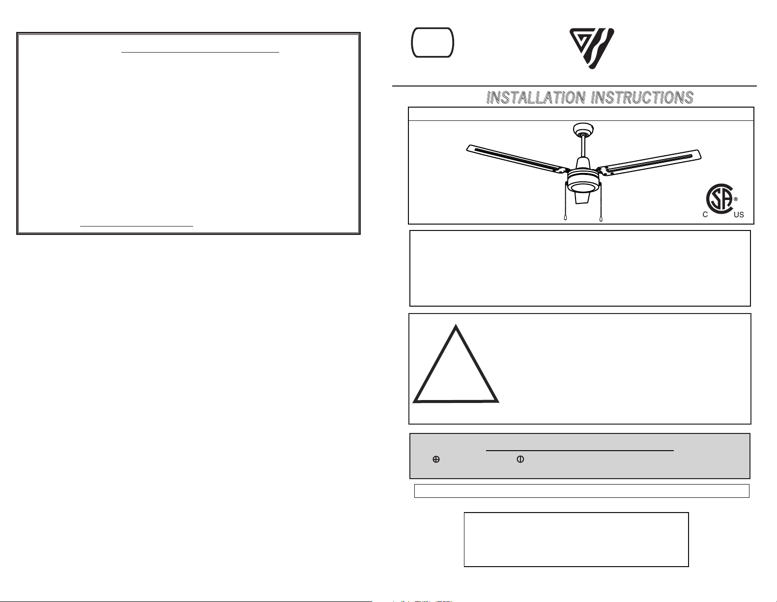
Model: Industrial
NOTE: FOR OPTIMUM QUIETNESS, FULLY ASSEMBLE FAN AND RUN 24 HOURS
TOOLS AND MATERIALS REQUIRED
- Step Ladder
- Wire Cutters
- Wiring supplies as required by electrical code.
QUESTIONS OR CONCERNS CONTACT AT:
1-800-265-1833 (English)
1-800-567-2513 (French)
Monday through Friday 8:00 a.m. to 5:00 p.m. E.S.T.
2157 Parkedale Ave.,
Brockville, Ontario
K6V 5V6
PH: (613) 342-5424
FX: (613) 342-8437
2555 Rue Bernard
Lefebvre, Laval, Quebec
H7C 0A5
PH: (450) 665-2535
FX: (450) 665-0910
I
I
N
N
S
S
T
T
A
A
L
L
L
L
A
A
T
T
I
I
O
O
N
N
I
I
N
N
S
S
T
T
R
R
U
U
C
C
T
T
I
I
O
O
N
N
S
S
- Screwdriver
- Screwdriver
CP-2
LED
11/16
“Thank you” for purchasing our product. It is our policy to furnish you with high quality
products at a fair price. With proper installation your fan should provide you with years of
money saving comfort.
This fan is guaranteed to be free from defects in workmanship and Material for a period
of five (5) years from date of purchase. Within the first (1) year from date of purchase any
defective product should be returned to your RETAIL OUTLET along with proof of purchase.
For the balance of the warranty, four (4) years, the MOTOR WINDINGS ONLY shall be free
of defects. We will correct such defects or replace the motor assembly at our option if the
product is returned, FREIGHT PREPAID, to us. The returned fan must be accompanied by
your proof of purchase and a cheque for $20.00 for handling and labour charges. All costs of
removing and re-installing the product are YOUR RESPONSIBILITY damage to any part as
such by accident, misuse, improper installation or by affixing any accessories IS NOT covered
by this warranty. As a result of varying climatic conditions in our area this warranty does not
cover any changes in finishes, including rusting, pitting, corroding, tarnishing or peeling.
WARRANTY VOID: In cases of alteration, abuse, installation not in accordance with
instructions or REMOVAL Of the c.S.A. Sticker.
5 YEAR LIMITED WARRANTY
11/16
!
INSTRUCTIONS PE RTAINING TO RISK OF FIRE OR INJURY TO PERSONS
INSTALLATION AND WIRING TO BE IN ACCORDANCE WITH CEC,
NEC, LOCAL ELECTRICAL CODES and ANSI/NFPA 70.
Consult a qualified electrician if you are not familiar with wiring.
READ ALL INST RUCTIONS
IMPO RTANT SAFETY
INSTRUCTIONS
SAVE THESE INSTRUCTIONS
Note to Installer
You are obligated to pass these instructions on to building
maintenance or location Supervisor for
maintenance of this product.
WARNING
1.
To
reduce
the
risk
of
personal
injury DO
NOT bend
the
blade
brackets
when
installing
the
brackets,
balancing
the
blades
or
cleaning
the
fan. Also,
DO
NOT insert
foreign
objects
in
between
rotating
fan
blades.
Mount
with
the
lowest
moving
parts
at
least
above
floor
or
grade
level.
SAFETY PRECAUTIONS
1. Turn off power at main electrical service box before starting installation.
2. Electrical connections must comply with local code ordinances, national
electrical codes, CEC, NEC and ANSI/NFPA 70.
3. Make sure the installation site you choose allows the fan blades to rotate
freely without any obstructions.
4. When mounting the fan on a ceiling outlet box, Use an approved (CSA for
Canada and UL for U.S.) ceiling fan box marked "FOR FAN SUPPORT".
5. WARNING: To reduce the risk of fire, electric shock, or personal injury,
6. Total Fan Weight: approximate 5.5 kgs (12.13 lbs).
mount fan only to an outlet box marked acceptable for fan support and use
mounting screws provided with the outlet box. Most outlet boxes commonly
used for the support of lighting fixtures are not acceptable for fan support
and may need to be replaced. Consult a qualified electrician if in doubt.
Remove fan from the carton carefully and check for shipping damage.
Check blades for bends and dents. In case assistance is required please
contact our service centre.
All set screws must be checked and re-tightened where necessary after
installation. No lubricants should be used on screws
or hooks.
To
reduce the risk of personal injury install the safety cable (per Fig. 1).
DO NOT attach blades before hanging the fan.
2.
3.
4.
5.
6.
3.05 Meters
(10 Feet)
Ensure the outlet box is securely installed in place such that it is able to
support at least the fan weight.
2
INSTRUCTIONS
A
ceiling
fan
has
a
completely
internal
switching
system
for
total
operation
by
way
of
pull
chains.
On
a
fan/light
combination,
pull
chains
will
exist: One
for
light,
on
and
off. The
second
is
for
fan
speeds. This
will
be
marked
(SPEED)
on
the
fan
switch
housing.
1st
Pull
will
give
fan
High
Speed
2nd
Pull
will
give
fan
Medium
Speed
3rd
Pull
will
give
fan
Low
Speed
4th
Pull
will
Shut
Fan
Off
The
third
pull
chain
is
for
Forward/Reverse#(Note:
Some
models
come
with
a
slide
switch
instead
of
a
pull
chain).
This
setting
would
usually
be
changed
twice
per
year. Downdraft
in
summer
to
create
a
wind
chill
to
give
a
cooling
effect.
Updraft
in
winter
to
circulate
the
hot
stratified
air
off
the
ceiling
and
back
down
to
the
floor
without
creating
a
wind
chill.
three
TROUBLESHOOTING
TROUBLE
SUGGESTIONS
- Check fuses and circuit breakers.
1. Fan will not start - Check wiring connections to fan.
- Check wiring connections in switch housing.
CAUTION: Turn power off for last two items.
2. Fan sounds noisy - Check to make sure that all screws in motor housing are snug.
- Check to make sure that blade bracket screws are tight.
- Allow a 24 hour break in period to eliminate most noises.
3. Fan wobbles - Check that all blades are screwed firmly into blade brackets.
or shakes
excessively.
- Check that blade brackets are secured firmly to motor.
- Check distance from tip of blades to ceiling.
- Check distance between blade tip to blade tip. All
measurements should be equal. Loosen blade
screws and position blade until even then re-tighten.
- Check to make sure that jam screws in downrod are tightened.
- Make sure canopy and mounting bracket are
tightened securely to wooden joist.
9
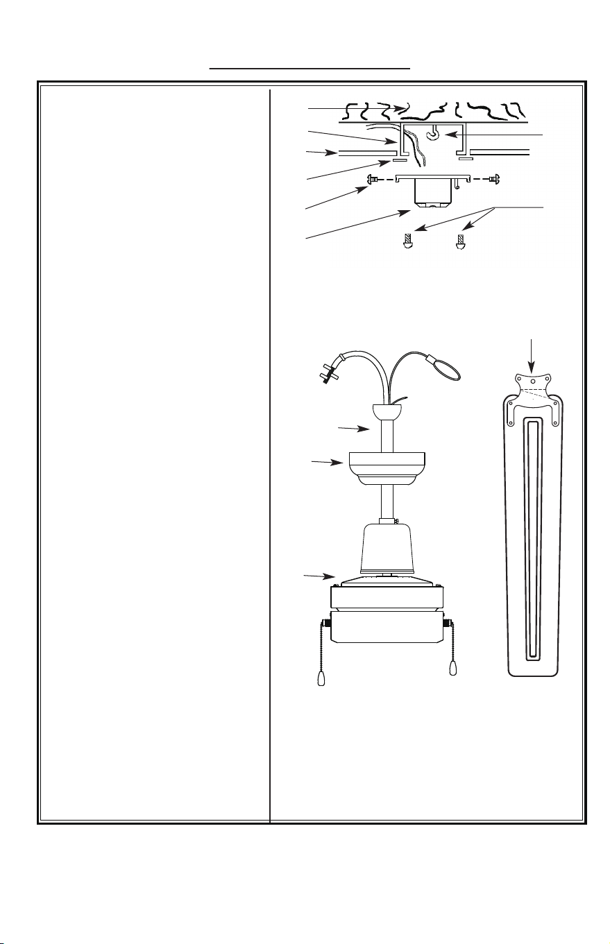
Fig. 1
1.
2.
3.
5.
7.
8.
4.
ASSEMBLY DRAWING
1. Wooden Joist
2. Approved(CSA for Canada
and UL for U.S.) ceiling fan box
(not provided)
3. Ceiling
4. J-Hook
5. Rubber Gasket
3
12.
6.
11.
10.
9.
8. Outlet Box Screws
(not provided)
12. Blade
9. Downrod c/w Ground Wire
10. Ceiling Canopy
11. Motor Assembly
6.Screws Lock Washers
(set of 4)
&
7. Mounting Bracket c/w Ground
Wire
3000 hours
Fig. 7
8
- When properly maintained, fans can be expected to give years of trouble
free operation.
- Properly maintained fans must be inspected every
3000 hours
for
- Refer to (Fig. 7) for maintenance schedule.
NOTE: If vibration and/or wear is noticeable the fan should be
removed from service and repaired or replaced by a
qualified person.
DATE INSTALLED:
Visible Vibration
Check Every
4 Months
Support Mechanism
Refer to Installation
Instructions
(Every 4 Months)
Screws
Refer to Installation
Instructions
(Every 4 Months)
• M A I N T E N A N C E •
vibration and wear on the support mechanism and that all screws, nuts,
etc. are tight.
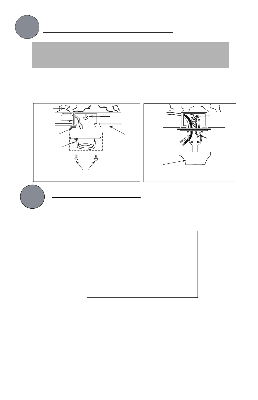
1.
INSTALL MOUNTING BRACKET
4
Canopy
J-Hook
Ceiling
- Install J-Hook through centre of outlet box and into the wooden joist.
- Secure mounting bracket and rubber gaskets to outlet box.
- Hang the safety cable onto the J-hook.
- Hang fan on mounting bracket.
WARNING: To Reduce The Risk Of Fi re, Electric Shock, Or Personal
Injury, Mount To UL/CSA Listed Outlet Box Marked Acceptable for
Fan Suppo rt And Use Mounting Sc rews Provided With The Outlet Box.
J-
Hook
Safety
Cable
Outlet box
Screws
(not provided)
CAUTION
SEE SAFETY PRECAUTIONS ON
PG. #2 BEFORE WIRING
Green Wire - GROUND
Black Wire (Fan) - POWER
White Wire (Fan) - COMMON
Red or Blue Wire (Light Kit) - POWER
ELECTRICAL HOOK UP
- There are several different wiring combinations that can be used in
controlling your ceiling fan to meet your specific requirements. Should
the following method not meet your requirements call or visit your nearest
Canarm distributor for a full list of fan accessories.
-
-
After making the wire connections, ensure the wires should be spread
apart with the grounded conductor and the equipment-grounding
conductor on one side of the outlet box and the ungrounded conductor
on the other side of the outlet box.
Ensure the splices after being made should be turned upward and
pushed carefully up into the outlet box.
Wood
Joist
Outlet Box
Rubber
Gasket
Mounting
Bracket
2.
Fig. 2a
Fig. 2b
7
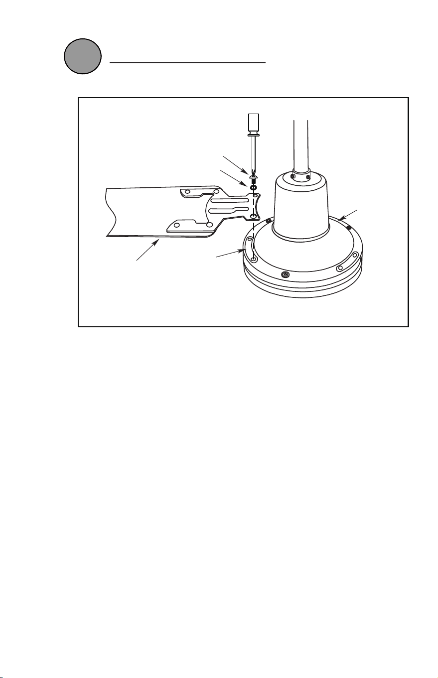
Mount the blade on motor assembly.
INSTALLATION
FINAL
Blade
Bracket Screw
Blade
Motor
Lock Washer
Fibre
Bracket
Gasket
Fig. 6
5.
2.
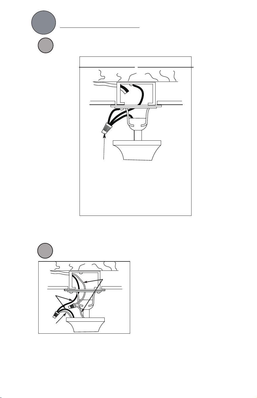
ELECTRICAL HOOK-UP
5
CONNECTING THE (GREEN) GROUND WIRE
- Connect ground wire from outlet box
to green wire from mounting bracket
and downrod using a
(not supplied).
NOTE: Once ground wires are connected, carefully tuck wires and into the
outlet box making sure that the wires are clear of the hemisphere and
downrod
when
positioned
in
mounting
bracket
(Downrod
Mount
Only).
DOWNROD MOUNT
A
Marette
marette
marette
CONNECTING BLACK, WHITE, AND (RED OR BLUE) WIRES
NOTE: Once wires are connected, carefully tuck wires and marrettes into the
outlet box making sure that the wires are clear of the hemisphere
and downrod when positioned in mounting bracket
(Downrod Mount Only).
B
- Connect white wire from outlet box to white
wire from fan using marret (not supplied).
- Connect black wire from outlet box to black
wire from fan plus (red or blue wire) using
a marret.
NOTE: A r
ed or blue wire would be power
for a light kit if applicable.
Black Wire
White Wire
Red or Blue
Wire
Fig. 3
Fig. 4
6
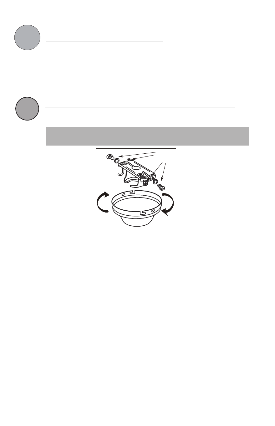
MOUNTING FAN ASSEMBLY
- Place two screws and washers on mounting plate (marked B on diagram)
which correspond with slots in canopy. Screw in two turns.
- Position canopy to mounting plate aligning slots to screws (marked B on
diagram) then turn to lock.
- Position and tighten the two screws and washers (marked A on diagram)
then tighten the two screws (marked B on diagram).
ENGAGE HEMISPHERE (Downrod Mount Only)
- Carefully rotate fan assembly until groove in hemisphere locks over tab of
canopy assembly.
NOTE: When installing fan on sloped ceiling, make sure tab on hanger bracket
faces towards the top of the slope. Depending on the slope, a longer
downrod may be required to prevent fan blades from hitting the ceiling.
WARNING: Failure to seat tab in groove could cause damage to
electrical wires and possible shock or fire hazard.
(A)
(B)
(B)
Washers
(A)
4.
3.
Fig. 5
2.
ELECTRICAL HOOK-UP
5
CONNECTING THE (GREEN) GROUND WIRE
- Connect ground wire from outlet box
to green wire from mounting bracket
and downrod using a
(not supplied).
NOTE: Once ground wires are connected, carefully tuck wires and into the
outlet box making sure that the wires are clear of the hemisphere and
downrod
when
positioned
in
mounting
bracket
(Downrod
Mount
Only).
DOWNROD MOUNT
A
Marette
marette
marette
CONNECTING BLACK, WHITE, AND (RED OR BLUE) WIRES
NOTE: Once wires are connected, carefully tuck wires and marrettes into the
outlet box making sure that the wires are clear of the hemisphere
and downrod when positioned in mounting bracket
(Downrod Mount Only).
B
- Connect white wire from outlet box to white
wire from fan using marret (not supplied).
- Connect black wire from outlet box to black
wire from fan plus (red or blue wire) using
a marret.
NOTE: A r
ed or blue wire would be power
for a light kit if applicable.
Black Wire
White Wire
Red or Blue
Wire
Fig. 3
Fig. 4
6
MOUNTING FAN ASSEMBLY
- Place two screws and washers on mounting plate (marked B on diagram)
which correspond with slots in canopy. Screw in two turns.
- Position canopy to mounting plate aligning slots to screws (marked B on
diagram) then turn to lock.
- Position and tighten the two screws and washers (marked A on diagram)
then tighten the two screws (marked B on diagram).
ENGAGE HEMISPHERE (Downrod Mount Only)
- Carefully rotate fan assembly until groove in hemisphere locks over tab of
canopy assembly.
NOTE: When installing fan on sloped ceiling, make sure tab on hanger bracket
faces towards the top of the slope. Depending on the slope, a longer
downrod may be required to prevent fan blades from hitting the ceiling.
WARNING: Failure to seat tab in groove could cause damage to
electrical wires and possible shock or fire hazard.
(A)
(B)
(B)
Washers
(A)
4.
3.
Fig. 5
1.
INSTALL MOUNTING BRACKET
4
Canopy
J-Hook
Ceiling
- Install J-Hook through centre of outlet box and into the wooden joist.
- Secure mounting bracket and rubber gaskets to outlet box.
- Hang the safety cable onto the J-hook.
- Hang fan on mounting bracket.
WARNING: To Reduce The Risk Of Fi re, Electric Shock, Or Personal
Injury, Mount To UL/CSA Listed Outlet Box Marked Acceptable for
Fan Suppo rt And Use Mounting Sc rews Provided With The Outlet Box.
J-
Hook
Safety
Cable
Outlet box
Screws
(not provided)
CAUTION
SEE SAFETY PRECAUTIONS ON
PG. #2 BEFORE WIRING
Green Wire - GROUND
Black Wire (Fan) - POWER
White Wire (Fan) - COMMON
Red or Blue Wire (Light Kit) - POWER
ELECTRICAL HOOK UP
- There are several different wiring combinations that can be used in
controlling your ceiling fan to meet your specific requirements. Should
the following method not meet your requirements call or visit your nearest
Canarm distributor for a full list of fan accessories.
-
-
After making the wire connections, ensure the wires should be spread
apart with the grounded conductor and the equipment-grounding
conductor on one side of the outlet box and the ungrounded conductor
on the other side of the outlet box.
Ensure the splices after being made should be turned upward and
pushed carefully up into the outlet box.
Wood
Joist
Outlet Box
Rubber
Gasket
Mounting
Bracket
2.
Fig. 2a
Fig. 2b
7
Mount the blade on motor assembly.
INSTALLATION
FINAL
Blade
Bracket Screw
Blade
Motor
Lock Washer
Fibre
Bracket
Gasket
Fig. 6
5.
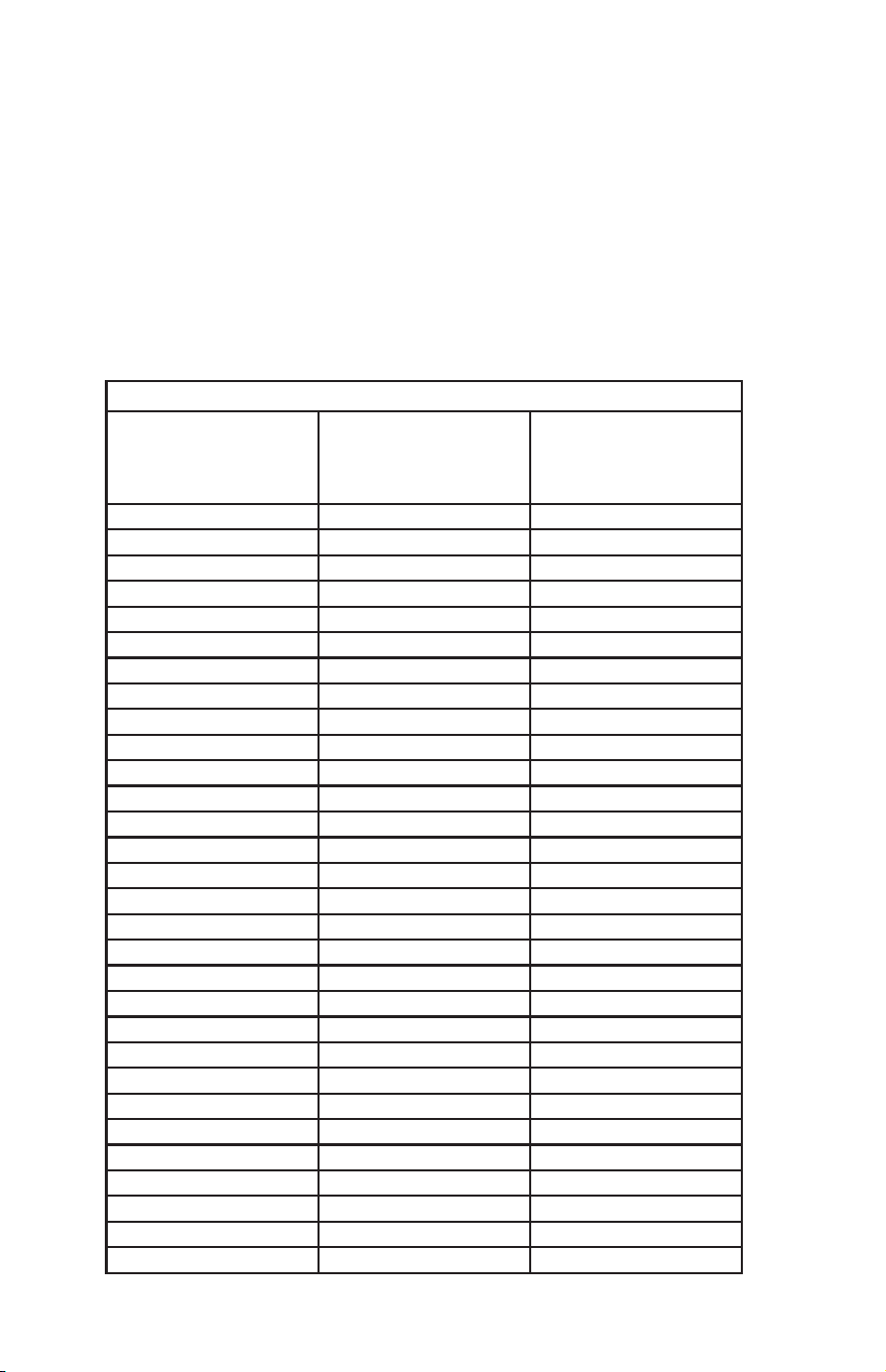
Fig. 1
1.
2.
3.
5.
7.
8.
4.
ASSEMBLY DRAWING
1. Wooden Joist
2. Approved(CSA for Canada
and UL for U.S.) ceiling fan box
(not provided)
3. Ceiling
4. J-Hook
5. Rubber Gasket
3
12.
6.
11.
10.
9.
8. Outlet Box Screws
(not provided)
12. Blade
9. Downrod c/w Ground Wire
10. Ceiling Canopy
11. Motor Assembly
6.Screws Lock Washers
(set of 4)
&
7. Mounting Bracket c/w Ground
Wire
3000 hours
Fig. 7
8
- When properly maintained, fans can be expected to give years of trouble
free operation.
- Properly maintained fans must be inspected every
3000 hours
for
- Refer to (Fig. 7) for maintenance schedule.
NOTE: If vibration and/or wear is noticeable the fan should be
removed from service and repaired or replaced by a
qualified person.
DATE INSTALLED:
Visible Vibration
Check Every
4 Months
Support Mechanism
Refer to Installation
Instructions
(Every 4 Months)
Screws
Refer to Installation
Instructions
(Every 4 Months)
• M A I N T E N A N C E •
vibration and wear on the support mechanism and that all screws, nuts,
etc. are tight.

WARNING
1.
To
reduce
the
risk
of
personal
injury DO
NOT bend
the
blade
brackets
when
installing
the
brackets,
balancing
the
blades
or
cleaning
the
fan. Also,
DO
NOT insert
foreign
objects
in
between
rotating
fan
blades.
Mount
with
the
lowest
moving
parts
at
least
above
floor
or
grade
level.
SAFETY PRECAUTIONS
1. Turn off power at main electrical service box before starting installation.
2. Electrical connections must comply with local code ordinances, national
electrical codes, CEC, NEC and ANSI/NFPA 70.
3. Make sure the installation site you choose allows the fan blades to rotate
freely without any obstructions.
4. When mounting the fan on a ceiling outlet box, Use an approved (CSA for
Canada and UL for U.S.) ceiling fan box marked "FOR FAN SUPPORT".
5. WARNING: To reduce the risk of fire, electric shock, or personal injury,
6. Total Fan Weight: approximate 5.5 kgs (12.13 lbs).
mount fan only to an outlet box marked acceptable for fan support and use
mounting screws provided with the outlet box. Most outlet boxes commonly
used for the support of lighting fixtures are not acceptable for fan support
and may need to be replaced. Consult a qualified electrician if in doubt.
Remove fan from the carton carefully and check for shipping damage.
Check blades for bends and dents. In case assistance is required please
contact our service centre.
All set screws must be checked and re-tightened where necessary after
installation. No lubricants should be used on screws
or hooks.
To
reduce the risk of personal injury install the safety cable (per Fig. 1).
DO NOT attach blades before hanging the fan.
2.
3.
4.
5.
6.
3.05 Meters
(10 Feet)
Ensure the outlet box is securely installed in place such that it is able to
support at least the fan weight.
2
INSTRUCTIONS
A
ceiling
fan
has
a
completely
internal
switching
system
for
total
operation
by
way
of
pull
chains.
On
a
fan/light
combination,
pull
chains
will
exist: One
for
light,
on
and
off. The
second
is
for
fan
speeds. This
will
be
marked
(SPEED)
on
the
fan
switch
housing.
1st
Pull
will
give
fan
High
Speed
2nd
Pull
will
give
fan
Medium
Speed
3rd
Pull
will
give
fan
Low
Speed
4th
Pull
will
Shut
Fan
Off
The
third
pull
chain
is
for
Forward/Reverse#(Note:
Some
models
come
with
a
slide
switch
instead
of
a
pull
chain).
This
setting
would
usually
be
changed
twice
per
year. Downdraft
in
summer
to
create
a
wind
chill
to
give
a
cooling
effect.
Updraft
in
winter
to
circulate
the
hot
stratified
air
off
the
ceiling
and
back
down
to
the
floor
without
creating
a
wind
chill.
three
TROUBLESHOOTING
TROUBLE
SUGGESTIONS
- Check fuses and circuit breakers.
1. Fan will not start - Check wiring connections to fan.
- Check wiring connections in switch housing.
CAUTION: Turn power off for last two items.
2. Fan sounds noisy - Check to make sure that all screws in motor housing are snug.
- Check to make sure that blade bracket screws are tight.
- Allow a 24 hour break in period to eliminate most noises.
3. Fan wobbles - Check that all blades are screwed firmly into blade brackets.
or shakes
excessively.
- Check that blade brackets are secured firmly to motor.
- Check distance from tip of blades to ceiling.
- Check distance between blade tip to blade tip. All
measurements should be equal. Loosen blade
screws and position blade until even then re-tighten.
- Check to make sure that jam screws in downrod are tightened.
- Make sure canopy and mounting bracket are
tightened securely to wooden joist.
9
Model: Industrial
NOTE: FOR OPTIMUM QUIETNESS, FULLY ASSEMBLE FAN AND RUN 24 HOURS
TOOLS AND MATERIALS REQUIRED
- Step Ladder
- Wire Cutters
- Wiring supplies as required by electrical code.
QUESTIONS OR CONCERNS CONTACT AT:
1-800-265-1833 (English)
1-800-567-2513 (French)
Monday through Friday 8:00 a.m. to 5:00 p.m. E.S.T.
2157 Parkedale Ave.,
Brockville, Ontario
K6V 5V6
PH: (613) 342-5424
FX: (613) 342-8437
2555 Rue Bernard
Lefebvre, Laval, Quebec
H7C 0A5
PH: (450) 665-2535
FX: (450) 665-0910
I
I
N
N
S
S
T
T
A
A
L
L
L
L
A
A
T
T
I
I
O
O
N
N
I
I
N
N
S
S
T
T
R
R
U
U
C
C
T
T
I
I
O
O
N
N
S
S
- Screwdriver
- Screwdriver
CP-2
LED
11/16
“Thank you” for purchasing our product. It is our policy to furnish you with high quality
products at a fair price. With proper installation your fan should provide you with years of
money saving comfort.
This fan is guaranteed to be free from defects in workmanship and Material for a period
of five (5) years from date of purchase. Within the first (1) year from date of purchase any
defective product should be returned to your RETAIL OUTLET along with proof of purchase.
For the balance of the warranty, four (4) years, the MOTOR WINDINGS ONLY shall be free
of defects. We will correct such defects or replace the motor assembly at our option if the
product is returned, FREIGHT PREPAID, to us. The returned fan must be accompanied by
your proof of purchase and a cheque for $20.00 for handling and labour charges. All costs of
removing and re-installing the product are YOUR RESPONSIBILITY damage to any part as
such by accident, misuse, improper installation or by affixing any accessories IS NOT covered
by this warranty. As a result of varying climatic conditions in our area this warranty does not
cover any changes in finishes, including rusting, pitting, corroding, tarnishing or peeling.
WARRANTY VOID: In cases of alteration, abuse, installation not in accordance with
instructions or REMOVAL Of the c.S.A. Sticker.
5 YEAR LIMITED WARRANTY
11/16
!
INSTRUCTIONS PE RTAINING TO RISK OF FIRE OR INJURY TO PERSONS
INSTALLATION AND WIRING TO BE IN ACCORDANCE WITH CEC,
NEC, LOCAL ELECTRICAL CODES and ANSI/NFPA 70.
Consult a qualified electrician if you are not familiar with wiring.
READ ALL INST RUCTIONS
IMPO RTANT SAFETY
INSTRUCTIONS
SAVE THESE INSTRUCTIONS
Note to Installer
You are obligated to pass these instructions on to building
maintenance or location Supervisor for
maintenance of this product.