
Operator's Manual
CRRFr MRN
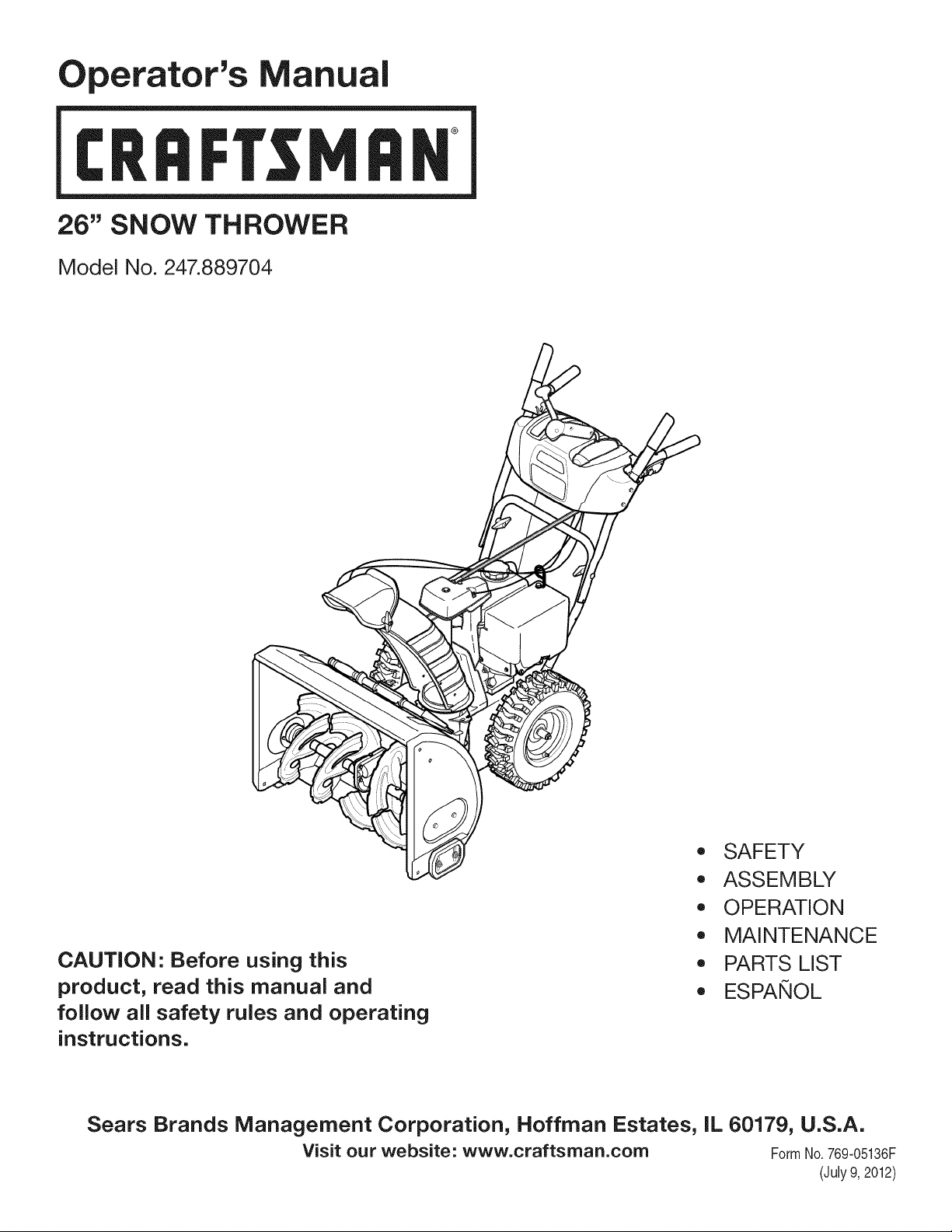
26" SNOW THROWER
Model No. 247.889704
CAUTION" Before using this
product, read this manual and
follow all safety rules and operating
instructions.
\
,, SAFETY
o ASSEMBLY
OPERATION
MAINTENANCE
PARTS LIST
o ESPANOL
Sears Brands Management Corporation, Hoffman Estates, IL 60179, U.S.A.
Visit our website: www.craftsman.com FormNo. 769-05136F
(July9, 2012)
WarrantyStatement.................... Page2
SafeOperationPractices.............. Pages3-6
Assembly......................... Pages8-13
Operation........................ Pages14-17
Service&Maintenance.............. Pages18-25
Off-SeasonStorage................... Page26
Troubleshooting...................... Page27
PartsList......................... Pages28-45
RepairProtectionAgreement............ Page49
Espadol............................. Page50
CRAFTSMANTWOYEARFULLWARRANTY
FORTWOYEARSfromthedateofpurchase,thisproductiswarrantedagainstanydefectsinmaterialorworkmanship.Defectiveproductwill
receivefreerepairorfreereplacementifrepairisunavailable.
ADDiTiONAL LiFETiME LiMiTED WARRANTY on UPPER and LOWER CHUTE
FORAS LONGAS IT IS USEDbythe originalownerafterthe secondyear fromthe dateof purchase,theupperandlowerchuteof this snow
throwerarewarrantedagainstany defectsinmaterialorworkmanshipas verifiedby a Searsauthorizedserviceprovider.Withproofof purchase,
youwill receivea newchutefree of charge.Youare responsiblefor the laborcost of installationandany costincurredto verify thedefect.
Forwarrantycoveragedetailsto obtainrepairor replacement,visitthe web site:www.craftsman.com
ThiswarrantycoversONLYdefectsin materialandworkmanship.Warrantycoveragedoes NOTinclude:
• Expendableitemsthat can wearoutfromnormalusewithinthewarrantyperiod,includingbut not limitedto augers,auger paddles,drift
cutters,skidshoes,shaveplate,shearpins,spark plug,air cleaner,belts,andoil filter.
• Standardmaintenanceservicing,oilchanges,or tune-ups.
Tire replacementor repaircausedby puncturesfromoutsideobjects,suchas nails,thorns,stumps,or glass.
• Tireor wheelreplacementor repairresultingfrom normalwear,accident,or improperoperationor maintenance.
Repairsnecessarybecauseof operatorabuse,includingbutnot limitedto damagecausedby over-speedingthe engine,or from impacting
objectsthat bendthe frame,augershaft,etc.
• Repairsnecessarybecauseof operatornegligence,includingbut not limitedto, electricaland mechanicaldamagecausedby improper
storage,failureto usethe propergradeandamountof engineoil, or failureto maintainthe equipmentaccordingto the instructionscontained
inthe operator'smanual.
• Engine(fuelsystem)cleaningor repairscausedbyfuel determinedto becontaminatedoroxidized(stale).in general,fuel shouldbeused
within30 daysof itspurchasedate.
Normaldeteriorationandwearof the exteriorfinishes,or productlabel replacement.
Thiswarrantyis void if thisproductis ever usedwhileprovidingcommercialservicesor if rentedto anotherperson.
Thiswarrantygivesyou specificlegalrights,andyou mayalso haveotherrightswhich varyfrom stateto state.
Sears Brands Management Corporation, Hoffman Estates, IL 60179
EngineOilType: 5W-30
EngineOilCapacity: 20ounces
FuelCapacity: 2 Quarts
SparkPlug: F6RTC(951-10292)
SparkPlugGap: .020"to .030"
ModelNumber.................................................................
Serial Number.................................................................
Dateof Purchase.............................................................
Recordthe modelnumber,serialnumber
anddateof purchaseabove
© Sears Brands,LLC
2
Thissymbolpointsout importantsafetyinstructionswhich,if not
followed,couldendangerthepersonalsafetyand/orpropertyof
yourselfand others. Readand followall instructionsin this manual
beforeattemptingto operatethismachine.Failureto complywith
theseinstructionsmayresultin personalinjury.Whenyou seethis
symbol,HEEDITSWARNING!
CALIFORNIA PROPOSITION 65
EngineExhaust,someof its constituents,and certainvehicle
componentscontainoremit chemicalsknownto Stateof California
to causecancerand birthdefectsor otherreproductiveharm,
Thismachinewas builtto beoperatedaccordingto the safeopera-
tion practicesinthis manual.As with anytypeof powerequipment,
carelessnessor erroron the partof the operatorcan resultin serious
injury.Thismachineis capableof amputatingfingers,hands,toes
andfeet andthrowingdebris.Failureto observethe followingsafety
instructionscouldresultin seriousinjuryor death.
Your Responsibility--Restrict the use of thispowermachineto
personswho read,understandandfollow thewarningsand instruc-
tionsin this manualand on the machine,
SAVE THESE INSTRUCTIONS!
TRAiNiNG
• Read,understand,and followall instructionson the machineand
in themanual(s)beforeattemptingto assembleandoperate.
Failureto do socan resultin seriousinjuryto the operatorand/
orbystanders.Keepthismanualin a safeplaceforfuture and
regularreferenceandfor orderingreplacementparts.
• Befamiliarwith all controlsand their properoperation.Knowhow
to stopthe machineand disengagethemquickly.
• Neverallowchildrenunder 14yearsof age to operatethis
machine.Children14andover shouldreadandunderstandthe
instructionsand safeoperationpracticesin thismanualandon
the machineandbe trainedandsupervisedby anadult.
Neverallowadultsto operatethis machinewithoutproper
instruction.
• Thrownobjectscan causeseriouspersonalinjury. Planyour
snow-throwingpatternto avoiddischargeof materialtoward
roads,bystandersand the like.
Keepbystanders,pets andchildrenat least75feetfromthe
machinewhile it is in operation.Stopmachineif anyoneenters
the area.
• Exercisecautionto avoidslippingor falling,especiallywhen
operatingin reverse.
PREPARATION
Thoroughlyinspectthearea wherethe equipmentisto be used.
Removeall doormats,newspapers,sleds,boards,wires andother
foreignobjects,whichcouldbe trippedoverorthrownby the auger/
impeller.
• Alwayswear safetyglassesor eyeshieldsduringoperationand
while performingan adjustmentor repairto protectyoureyes.
Thrownobjectswhichricochetcancauseseriousinjuryto the
eyes.
Donot operatewithoutwearingadequatewinteroutergarments.
Donot wearjewelry,long scarvesorotherlooseclothing,which
could becomeentangledin movingparts.Wearfootwearwhich
will improvefootingon slipperysurfaces.
Usea groundedthree-wireextensioncordand receptaclefor all
machineswith electricstartengines.
Disengageall controlleversbeforestartingthe engine.
Adjustcollectorhousingheightto cleargravelor crushedrock
surfaces.
• Neverattemptto make anyadjustmentswhileengineis running,
exceptwherespecificallyrecommendedinthe operator'smanual.
Letengineandmachineadjustto outdoortemperaturebefore
startingto clearsnow.
3
Safe Handling of Gasoline
Toavoidpersonalinjuryor propertydamageuseextremecare in
handlinggasoline.Gasolineis extremelyflammableandthe vaporsare
explosive.Seriouspersonalinjurycan occurwhengasolineis spilled
onyourselfor yourclotheswhichcan ignite. Washyour skinand
changeclothesimmediately.
• Useonlyan approvedgasolinecontainer.
• Extinguishall cigarettes,cigars,pipesandother sourcesof
ignition.
• Neverfuel machineindoors.
• Neverremovegas capor addfuel whilethe engineis hot or
running.
• Allowengineto coolat leasttwo minutesbeforerefueling.
• Neveroverfill fueltank. Fill tankto nomorethan1/2inchbelow
bottomof filler neck to providespace forfuel expansion.
• Replacegasolinecapandtighten securely.
• Ifgasolineis spilled,wipe it off theengineand equipment.Move
machineto anotherarea.Wait5 minutesbeforestartingthe
engine.
• Neverstorethe machineorfuel containerinsidewherethereis an
openflame,sparkor pilotlight(e.g. furnace,waterheater,space
heater,clothesdryeretc.).
• Allowmachineto cool at least5 minutesbeforestoring.
• Neverfill containersinsidea vehicleor ona truckor trailerbed
witha plasticliner.Alwaysplacecontainersonthe groundaway
fromyour vehiclebeforefilling.
• If possible,removegas-poweredequipmentfrom the truckor
trailerandrefuelit on the ground.Ifthis is not possible,then refuel
suchequipmenton a trailerwith a portablecontainer,ratherthan
froma gasolinedispensernozzle.
• Keepthe nozzlein contactwiththe rimof the fuel tank or
containeropeningat alltimes untilfuelingis complete.Do not use
a nozzlelock-opendevice.
OPERATION
• Do not puthandsorfeet near rotatingparts,in the auger/impeller
housingor chuteassembly.Contactwiththe rotatingpartscan
amputatehandsandfeet.
• Theauger/impellercontrolleveris a safetydevice.Neverbypass
itsoperation.Doingso makesthe machineunsafeand maycause
personalinjury.
• Thecontrolleversmustoperateeasilyin bothdirectionsand
automaticallyreturnto the disengagedpositionwhenreleased.
• Neveroperatewith a missingor damagedchuteassembly.Keep
all safetydevicesin placeand working.
• Neverrunan engineindoorsor ina poorlyventilatedarea. Engine
exhaustcontainscarbonmonoxide,an odorlessanddeadlygas.
• Do notoperatemachinewhileunderthe influenceof alcoholor
drugs.
• Mufflerand enginebecomehotand can causea burn.Do not
touch.Keepchildrenaway.
• Exerciseextremecautionwhenoperatingon or crossinggravel
surfaces.Stay alertfor hiddenhazardsor traffic.
Exercisecautionwhenchangingdirectionandwhileoperatingon
slopes.Do notoperateon steep slopes.
Planyoursnow-throwingpatternto avoiddischargetowards
windows,walls,carsetc. Thus,avoidingpossibleproperty
damageor personalinjurycausedby a ricochet.
Neverdirectdischargeat children,bystandersand petsor allow
anyoneinfront of the machine.
Donot overloadmachinecapacityby attemptingto clearsnowat
too fastof a rate.
Neveroperatethis machinewithoutgoodvisibility orlight. Always
be sureof yourfootingand keepa firm holdon the handles.Walk,
neverrun.
Disengagepowerto theauger/impellerwhentransportingor not
in use.
Neveroperatemachineat hightransportspeedson slippery
surfaces.Lookdownand behindand usecare whenbackingup.
Ifthe machineshouldstart to vibrateabnormally,stop the engine,
disconnectthe sparkplugwire and groundit againstthe engine.
Inspectthoroughlyfor damage.Repairanydamagebefore
startingandoperating.
Disengageall controlleversandstop enginebeforeyouleave
the operatingposition(behindthe handles).Waituntilthe auger/
impellercomesto a completestopbeforeuncloggingthechute
assembly,makingany adjustments,or inspections.
Neverput yourhandin the dischargeor collectoropenings.Do
not unclogchuteassemblywhileengineis running.Shutoff
engineand remainbehindhandlesuntilall movingpartshave
stoppedbeforeunclogging.
Useonly attachmentsandaccessoriesapprovedby the manufac-
turer (e.g.wheelweights,tire chains,cabsetc.). Forinformation
concerningtheseitems,call 1-800-469-4663.
Whenstartingengine,pull cord slowlyuntilresistanceis felt, then
pull rapidly.Rapidretractionof startercord(kickback)will pull
handand armtowardenginefasterthan youcan let go. Broken
bones,fractures,bruisesor sprainscould result.
Ifsituationsoccur whichare notcoveredinthis manual,use care
andgood judgment.
Toorderparts or scheduleservicefor thisproduct,call 1-800-
469-4663.
CLEARING A CLOGGED DISCHARGE CHUTE
Handcontactwith the rotatingimpellerinsidethe dischargechute
is the mostcommoncauseof injuryassociatedwith snowthrowers.
Neveruse yourhandto cleanout thedischargechute.
Toclear thechute:
1. SHUTTHEENGINEOFF!
2. Wait 10secondsto be surethe impellerbladeshavestopped
rotating.
3. Alwaysusea clean-outtool,not yourhands.
4
MAINTENANCE & STORAGE
• Nevertamperwithsafetydevices.Checktheirproperoperation
regularly.Referto the maintenanceand adjustmentsectionsof
thismanual.
• Beforecleaning,repairing,or inspectingmachinedisengageall
controlleversandstop the engine.Wait untilthe auger/impeller
cometo a completestop.Disconnectthe sparkplugwireand
groundagainsttheengineto preventunintendedstarting.
Checkboltsand screwsfor propertightnessat frequentintervals
to keepthe machineinsafe workingcondition.Also, visually
inspectmachinefor anydamage.
Do notchangetheenginegovernorsettingor over-speedthe
engine.Thegovernorcontrolsthe maximumsafeoperatingspeed
of the engine.
Snowthrowershaveplatesand skidshoesare subjectto wear
anddamage.Foryoursafetyprotection,frequentlycheckall
componentsand replacewith originalequipmentmanufacturer's
(OEM)partsonlyas listed inthe Partspagesof thisoperator's
manual.Useof partswhich donot meetthe originalequipment
specificationsmayleadto improperperformanceand compro-
misesafety!
Checkcontrolleversperiodicallyto verifytheyengageand disen-
gageproperlyandadjust,if necessary.Referto the adjustment
sectioninthisoperator'smanualfor instructions.
Maintainor replacesafetyandinstructionlabels,as necessary.
Observeproperdisposallawsand regulationsfor gas,oil,etc. to
protectthe environment.
Priorto storing,run machinea few minutestoclear snowfrom
machineand preventfreezeupof auger/impeller.
Neverstorethe machineorfuel containerinsidewherethereisan
openflame,sparkor pilot lightsuchas a waterheater,furnace,
clothesdryer etc.
Alwaysreferto the operator'smanualfor properinstructionson
off-seasonstorage.
Checkfuelline,tank, cap,andfittings frequentlyfor cracksor
leaks.Replaceif necessary.
Do notcrankenginewith sparkplug removed.
Accordingto the ConsumerProductsSafetyCommission(CPSC)
andthe U.S.EnvironmentalProtectionAgency(EPA),thisproduct
hasan AverageUsefulLifeof seven(7)years,or 60 hoursof
operation.At the endof theAverageUsefulLifehavethe machine
inspectedannuallybyan authorizedservicedealerto ensurethat
allmechanicalandsafetysystemsare workingproperlyand not
wornexcessively.Failureto do so can resultinaccidents,injuries
ordeath.
DO NOT MODIFY ENGINE
Toavoidseriousinjuryor death,do not modifyengine inany way.
Tamperingwiththe governorsettingcanleadto a runawayengineand
causeit to operateat unsafespeeds.Nevertamperwithfactory setting
of enginegovernor.
NOTICE REGARDING EMiSSiONS
Engineswhich arecertifiedtocomplywith Californiaandfederal
EPAemissionregulationsfor SORE(SmallOff RoadEquipment)are
certifiedto operateon regularunleadedgasoline,and mayinclude
the followingemissioncontrol systems:EngineModification(EM),
OxidizingCatalyst(OC), SecondaryAirInjection(SAI)and ThreeWay
Catalyst(TWO)if so equipped.
SPARK ARRESTOR
Thismachineisequippedwith aninternalcombustionengineand
shouldnotbe usedonor nearany unimprovedforest-covered,
brush-coveredor grass-coveredlandunlessthe engine'sexhaust
systemisequippedwith a sparkarrestormeetingapplicablelocalor
statelaws(if any)
Ifa sparkarrestoris used, it shouldbe maintainedin effectiveworking
orderby theoperator.Inthe State of Californiathe aboveis required
bylaw (Section4442of the CaliforniaPublicResourcesCode). Other
statesmayhavesimilarlaws. Federallawsapplyon federallands.
A sparkarrestorfor the muffleris availablethroughyournearestSears
PartsandRepairServiceCenter.
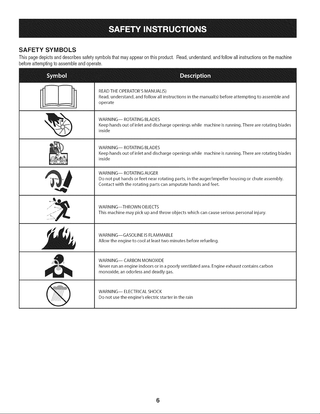
SAFETY SYMBOLS
Thispagedepictsand describessafetysymbolsthatmayappearonthisproduct. Read,understand,and followall instructionson the machine
beforeattemptingto assembleandoperate.
. +
i
i
"JIp
READ THE OPERATOR'S MANUAL(S)
Read, understand, and follow all instructions in the manual(s) before attempting to assemble and
operate
WARNING-- ROTATING BLADES
Keep hands out of inlet and discharge openings while machine is running. There are rotating blades
inside
WARNING-- ROTATING BLADES
Keep hands out of inlet and discharge openings while machine is running. There are rotating blades
inside
WARNING-- ROTATING AUGER
Do not put hands or feet near rotating parts, in the auger/impeller housing or chute assembly.
Contact with the rotating parts can amputate hands and feet.
WARNING--THROWN OBJECTS
This machine may pick up and throw objects which can cause serious personal injury.
WARNING--GASOLINE IS FLAMMABLE
Allow the engine to cool at least two minutes before refueling.
WARNING-- CARBON MONOXIDE
Never run an engine indoors or in a poorly ventilated area. Engine exhaust contains carbon
monoxide, an odorless and deadly gas+
WARNING-- ELECTRICAL SHOCK
Do not use the engine's electric starter in the rain
6

Thispageleftintentionallyblank.
7
NOTE:Referencesto rightorleft sideof the snowthrowerare
determinedfrombehindthe unit in the operatingposition(standing
directlybehindthe snowthrower,facingthe handlepanel).
REMOVING FROM CARTON
1. Cutthe cornersof thecartonand lay the sidesflaton the ground.
Removeand discardall packinginserts.
2. Movethe snowthrowerout of thecarton.
3. Makecertainthe carton has beencompletelyemptiedbefore
discardingit.
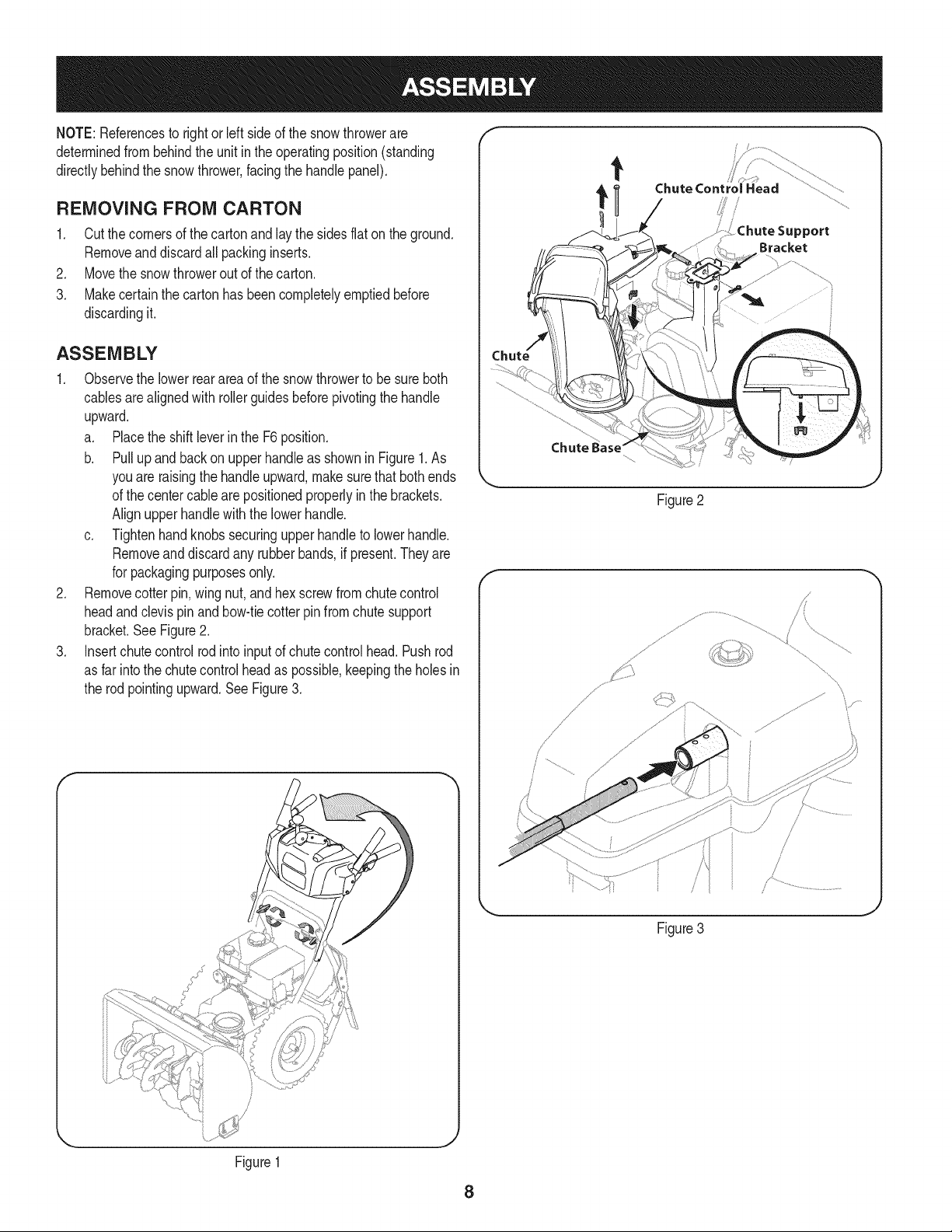
ASSEMBLY
1. Observethe lowerrearareaof the snowthrowerto be sure both
cablesarealignedwith rollerguidesbeforepivotingthe handle
upward.
a. Placethe shiftleverin the F6position.
b. Pullupand backon upperhandleas shownin Figure1.As
youare raisingthe handleupward,make surethat bothends
of the centercablearepositionedproperlyinthe brackets.
Alignupperhandlewith the lowerhandle.
c. Tightenhandknobssecuringupperhandleto lowerhandle.
Removeand discardany rubberbands,if present.Theyare
for packagingpurposesonly.
2. Removecotter pin,wingnut,and hexscrewfromchute control
headandclevis pin andbow-tiecotterpin fromchutesupport
bracket.See Figure2.
3. Insertchutecontrolrodintoinputof chutecontrolhead.Pushrod
as far intothe chutecontrolheadas possible,keepingthe holesin
the rodpointingupward.SeeFigure3.
/
Chute Control Head
_ort
Bracket
Figure2
f
/
/
/
Figure3
J
J
Figure1
8
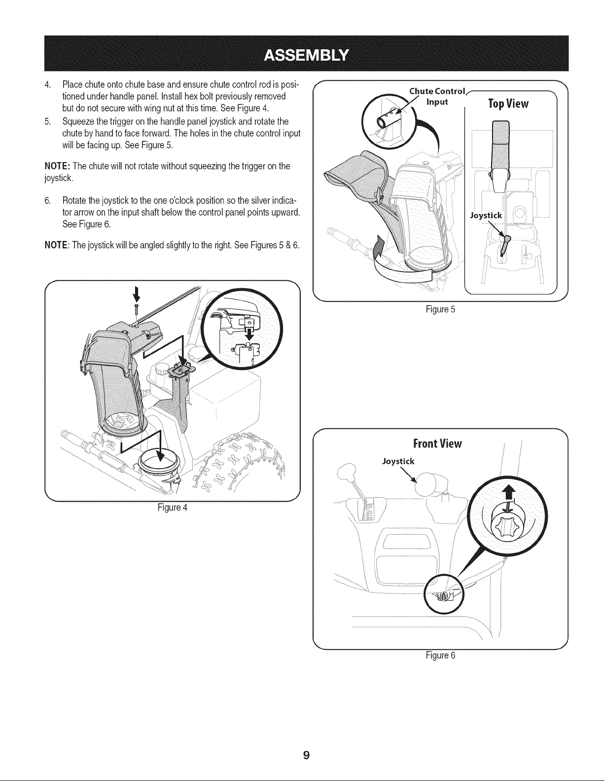
4. Placechuteontochutebaseandensurechutecontrolrodis posi-
tionedunderhandlepanel.Installhex boltpreviouslyremoved
but donot securewith wingnut at thistime.See Figure4.
5. Squeezethe triggeron thehandlepaneljoystickand rotatethe
chuteby handto face forward.Theholes in the chutecontrolinput
will befacing up.SeeFigure5.
NOTE:The chutewill not rotatewithoutsqueezingthe triggeronthe
joystick.
6. Rotatethejoystickto the oneo'clockpositionsothe silverindica-
tor arrowon the inputshaftbelowthe controlpanel pointsupward.
SeeFigure6.
NOTE:Thejoystickwill beangledslightlyto theright.SeeFigures5 & 6.
Figure4
f
Chute Controlf
Figure5
f
FroatView
Joystick
Figure6
J
9
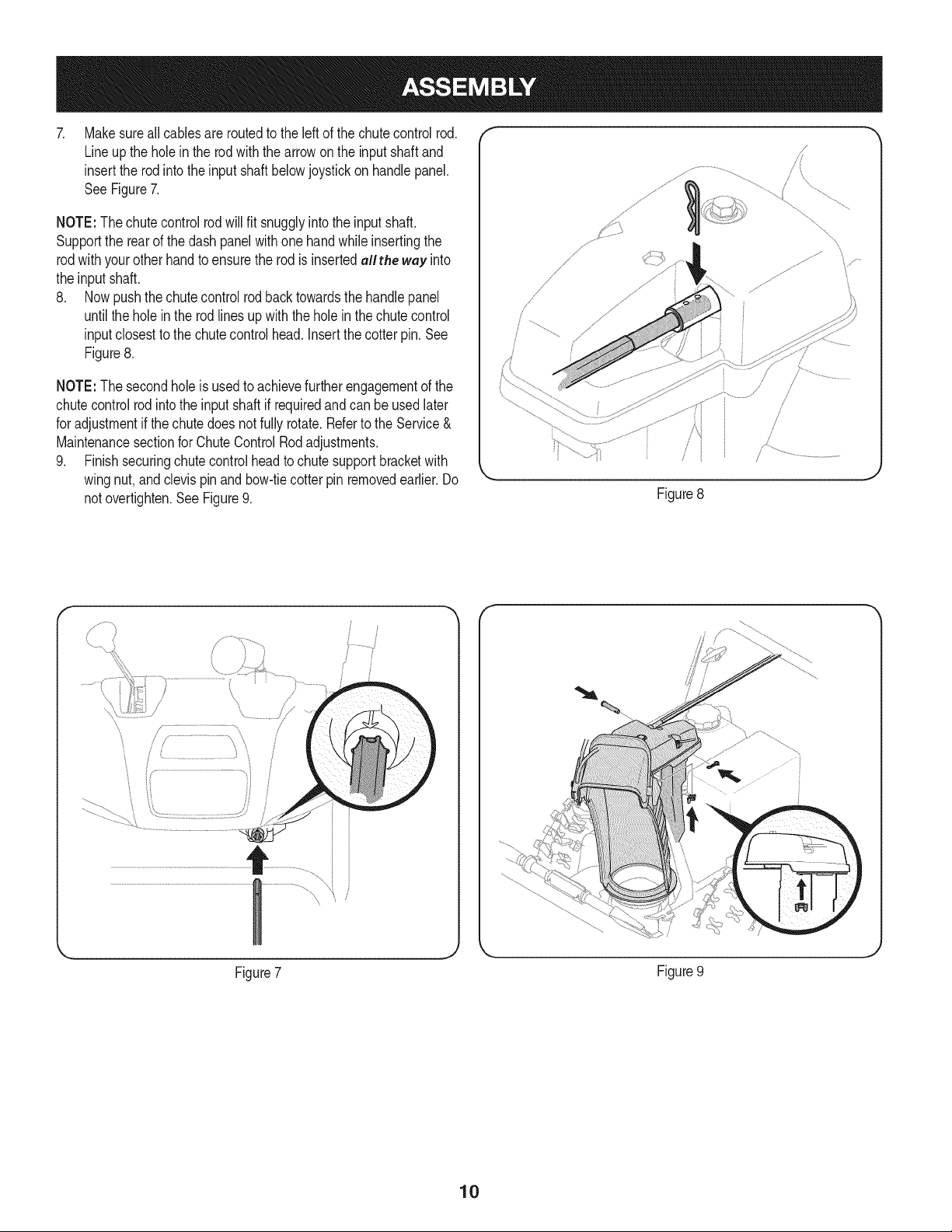
Makesureall cablesare routedto the left of the chutecontrolrod.
Lineup the holein the rodwith the arrowonthe inputshaftand
insertthe rod intothe inputshaftbelowjoystickonhandlepanel.
SeeFigure7.
NOTE:The chutecontrolrodwill fit snugglyintothe inputshaft.
Supportthe rearof the dashpanelwithone handwhile insertingthe
rodwith yourother handto ensurethe rod is insertedallthe way into
the inputshaft.
8. Nowpushthechutecontrolrod backtowardsthe handlepanel
untilthe holein the rod linesupwith the holein thechute control
inputclosestto the chutecontrolhead.Insertthecotter pin.See
Figure8.
NOTE:The secondholeis usedto achievefurtherengagementof the
chutecontrolrod intothe inputshaft if requiredand can be usedlater
for adjustmentif thechutedoesnot fully rotate.Referto the Service&
Maintenancesectionfor ChuteControlRodadjustments.
9. Finishsecuringchutecontrolheadto chutesupportbracketwith
wingnut,and clevispinand bow-tiecotter pin removedearlier.Do
notovertighten.SeeFigure9.
Figure8
\
y..................
Figure7
Figure9
10
iili,
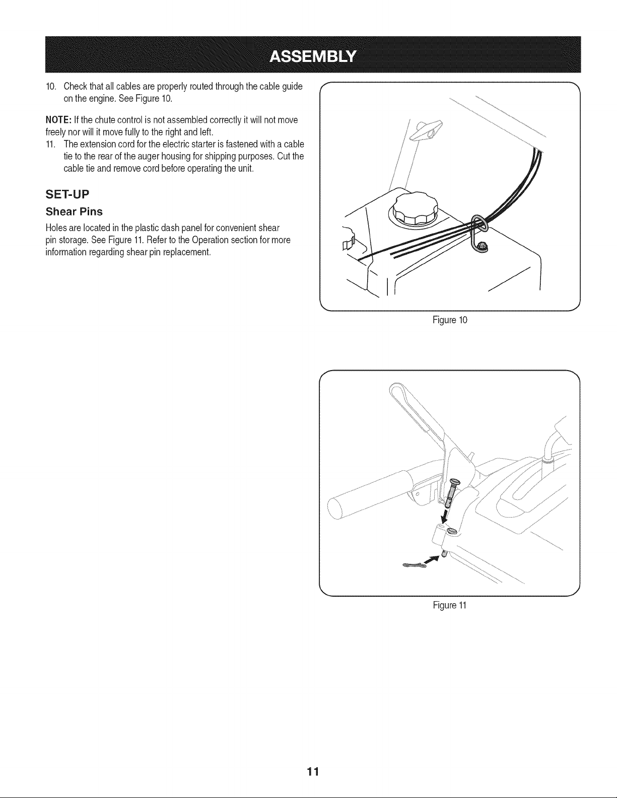
10. Checkthatall cablesare properlyroutedthroughthecable guide
onthe engine.See Figure10.
NOTE: Ifthe chutecontrol is notassembledcorrectlyit will not move
freelynorwill it movefully to the rightandleft.
11. Theextensioncordfor the electricstarteris fastenedwith a cable
tie to the rearof theauger housingfor shippingpurposes.Cutthe
cabletie and removecordbeforeoperatingthe unit.
SET-UP
Shear Pins
Holesare locatedinthe plasticdashpanelfor convenientshear
pinstorage.See Figure11.Referto the Operationsectionfor more
informationregardingshearpin replacement.
/
i
i I
!
Figure10
Figure11
J
11
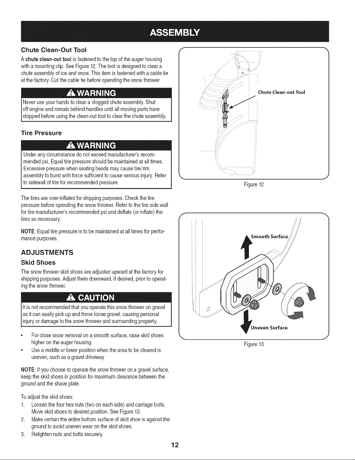
Chute Clean=Out Tool
Achute clean-out tool is fastenedto the top of the augerhousing
witha mountingclip. SeeFigure12.The tool is designedto cleara
chuteassemblyof ice andsnow.Thisitem is fastenedwith a cabletie
at the factory.Cut thecable tie beforeoperatingthe snowthrower.
loff m=ovingpartshave
stoppedbeforeusingthe clean-outtool to clear thechuteassembly.
Tire Pressure
Underanycircumstancedo notexceedmanufacturer'srecom-
mendedpsi. Equaltire pressureshouldbe maintainedat all times.
Excessivepressurewhenseatingbeadsmaycausetire/rim
assemblyto burstwith forcesufficientto causeseriousinjury.Refer
to sidewallof tirefor recommendedpressure.
................
Chute Clean-out Tool
_J
Figure12
Thetiresare over-inflatedfor shippingpurposes.Checkthetire
pressurebeforeoperatingthe snow thrower.Referto the tire sidewall
for tiremanufacturer'srecommendedpsianddeflate(or inflate)the
tiresas necessary.
NOTE:Equaltire pressureis to be maintainedat alltimesfor perfor-
mancepurposes.
ADJUSTMENTS
Skid Shoes
The snowthrowerskidshoesare adjustedupwardat thefactory for
shippingpurposes.Adjustthemdownward,if desired,priorto operat-
ingthe snowthrower.
It is not recommendedthat youoperatethis snowthroweron gravel
as it can easilypickup and throwloosegravel,causingpersonal
njuryordamageto the snowthrowerand surroundng property.
• Forclosesnow removalona smoothsurface,raiseskid shoes
higheronthe auger housing.
• Usea middleor lowerpositionwhentheareato be clearedis
uneven,suchas a graveldriveway
//'
Smooth Surface
Surface
Figure13
NOTE:If youchooseto operatethe snowthrowerona gravelsurface,
keepthe skidshoesin positionfor maximumclearancebetweenthe
groundandthe shaveplate.
Toadjustthe skidshoes:
1. Loosenthe four hexnuts(two oneach side)and carriagebolts.
Moveskidshoesto desiredposition.SeeFigure13.
2. Makecertainthe entirebottomsurfaceof skidshoeis againstthe
groundto avoidunevenwearon the skidshoes.
3. Retightennutsand boltssecurely.
12
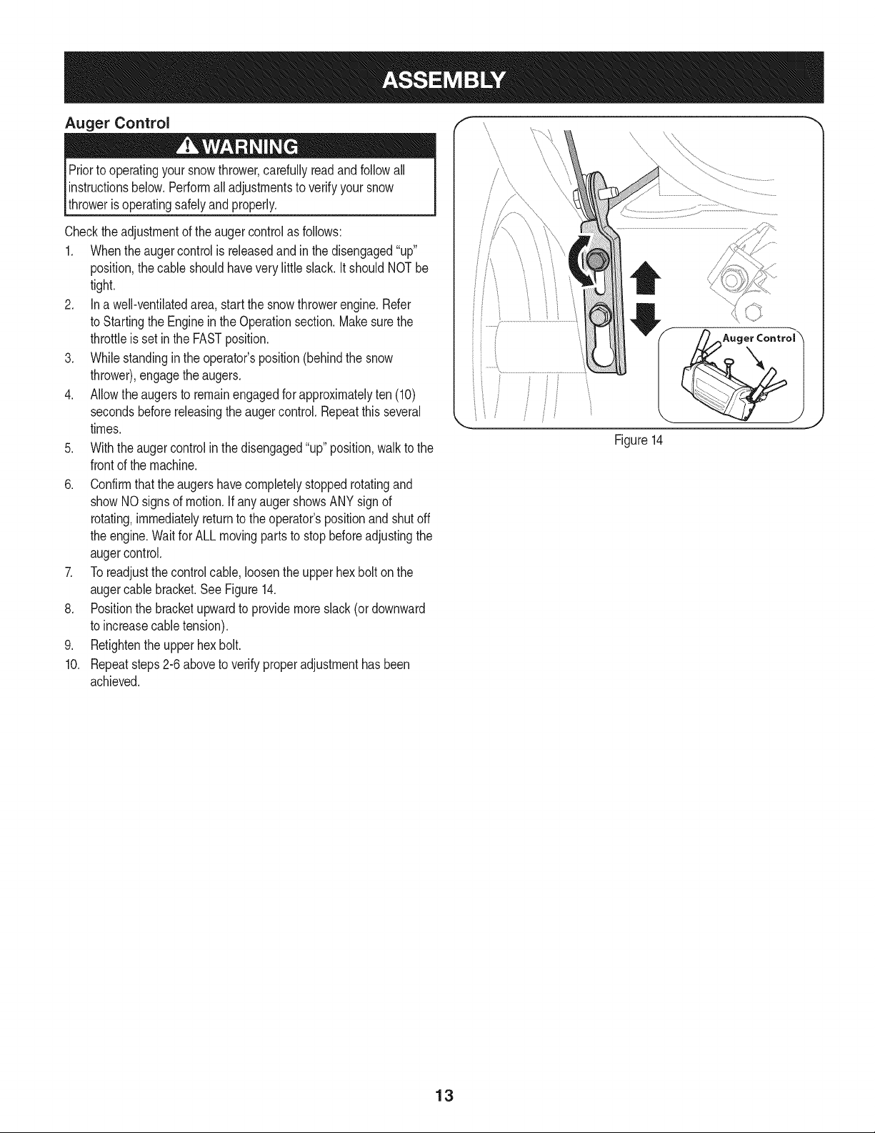
Auger Control
Priorto operatingyoursnowthrower,carefullyread andfollowall
instructionsbelow.Performall adjustmentsto verifyyoursnow
throweris operatingsafelyand properly.
Checktheadjustmentof the augercontrolas follows:
1. Whentheaugercontrolis releasedandin the disengaged"up"
position,the cableshouldhavevery littleslack. ItshouldNOTbe
tight.
2. In a well-ventilatedarea,start the snowthrowerengine.Refer
to Startingthe Engineinthe Operationsection.Makesurethe
throttleis setin the FASTposition.
3. Whilestandinginthe operator'sposition(behindthe snow
thrower),engagethe augers.
4. Allowtheaugersto remainengagedfor approximatelyten (10)
secondsbeforereleasingthe augercontrol.Repeatthis several
times.
5. Withtheaugercontrolin thedisengaged"up" position,walkto the
frontof the machine.
6. Confirmthatthe augershavecompletelystoppedrotatingand
showNOsignsof motion.If anyaugershowsANY signof
rotating,immediatelyreturnto the operator'spositionand shutoff
the engine.Waitfor ALL movingpartsto stop beforeadjustingthe
augercontrol.
7. Toreadjustthecontrolcable,loosentheupperhexbolt onthe
augercablebracket.SeeFigure14.
8. Positionthe bracketupwardto providemoreslack(or downward
to increasecabletension).
9. Retightenthe upperhex bolt.
10. Repeatsteps2-6 aboveto verifyproperadjustmenthasbeen
achieved.
/_Auger Control \
Figure14
13
f
Drive Control
Shift Lever
Four-Way Chute ControP (Joystick)
J
J
Auger Control
Chute Assembly
Gas Cap
\
\
\
\
\
Auger
Hous_
Clean Out
Tool
\
Augers
Muffler Recoil Starter
'\ Handle
Primer FUEL LEVEL
\
\
Choke
Control
_ Skid Shoe
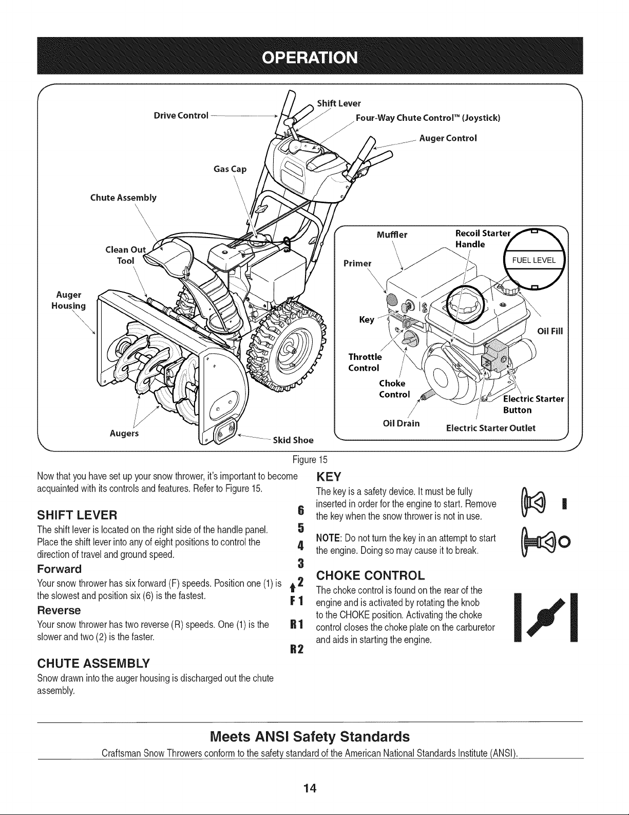
Figure15
Nowthat youhavesetup yoursnowthrower,it's importantto become
acquaintedwith itscontrolsandfeatures.Referto Figure15.
SHIFT LEVER 6
The shiftleveris locatedonthe rightsideof the handle panel. 5
Placethe shiftleverinto anyof eightpositionsto controlthe 4
directionof traveland groundspeed.
Forward 3
Yoursnowthrowerhas sixforward(F) speeds.Positionone (1)is t 2
the slowestand positionsix (6) is the fastest. F 1
Reverse
Yoursnowthrowerhastwo reverse(R) speeds.One(1) is the
slowerandtwo (2) is the faster.
CHUTE ASSEMBLY
Snowdrawnintothe augerhousingis dischargedout the chute
assembly.
Oil Drain
Key
Throttle
Control
=lectric Starter
Button
Electric Starter Outlet
KEY
The keyis a safetydevice.It mustbe fully
insertedinorderfor the engineto start. Remove
the keywhenthe snowthroweris not in use.
NOTE: Donot turnthe keyin an attemptto start
the engine.Doingso may causeit to break.
CHOKE CONTROL
The chokecontrolis foundon the rearof the
engineand is activatedby rotatingthe knob
to the CHOKEposition.Activatingthe choke
controlclosesthe chokeplateon the carburetor
andaids in startingthe engine.
Meets ANSi Safety Standards
CraftsmanSnowThrowersconformto the safetystandardof the AmericanNationalStandardsInstitute(ANSI).
14
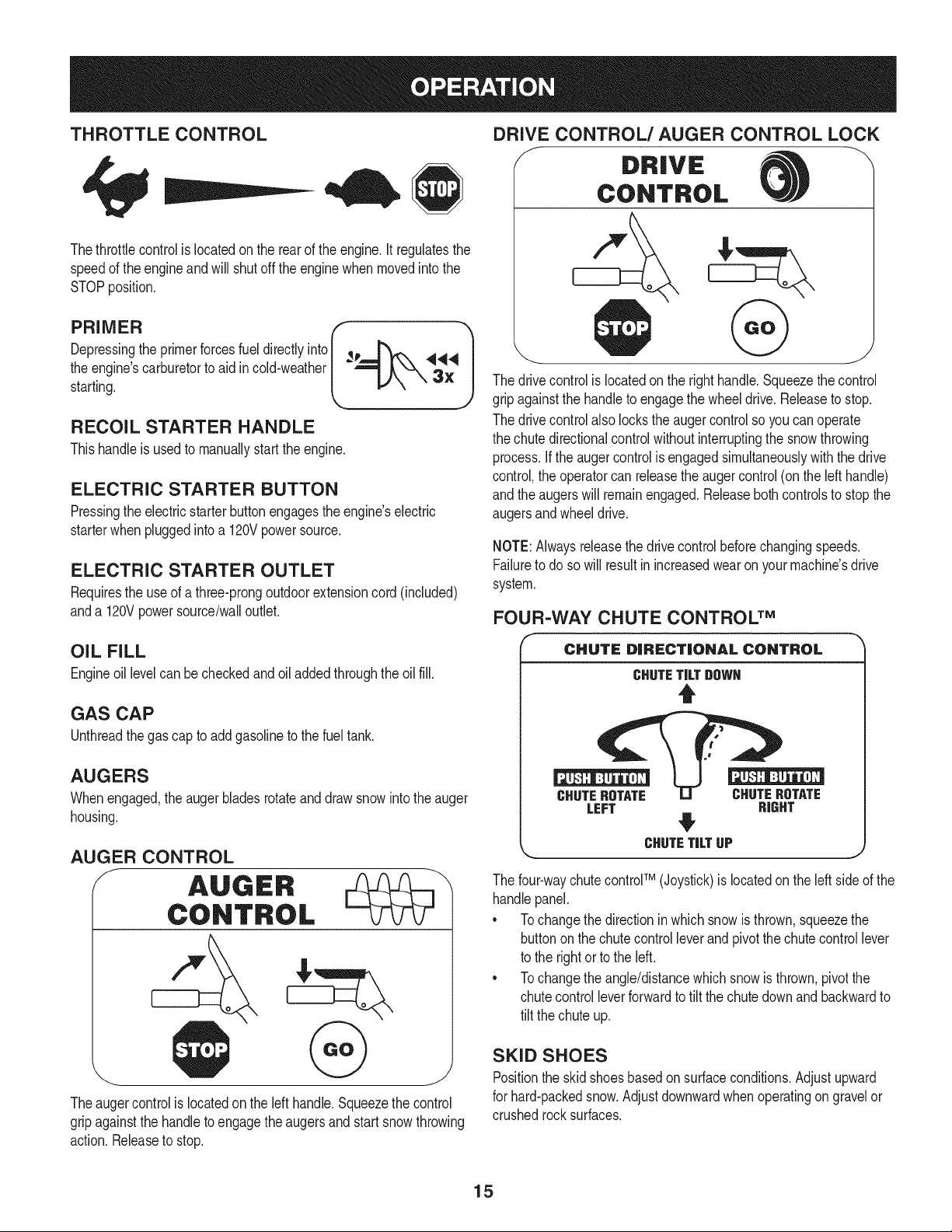
THROTTLE CONTROL
Thethrottlecontrolis locatedon the rearof the engine.It regulatesthe
speedof theengineand will shutoff the enginewhenmovedintothe
STOPposition.
Depressingthe primerforcesfuel directlyinto _p
the engine'scarburetorto aid incold-weather
starting.
RECOIL STARTER HANDLE
Thishandleis usedto manuallystartthe engine.
ELECTRIC STARTER BUTTON
Pressingthe electricstarterbuttonengagesthe engine'selectric
starterwhenpluggedintoa 120Vpowersource.
ELECTRIC STARTER OUTLET
Requiresthe useof athree-prongoutdoorextensioncord(included)
anda 120Vpowersource/walloutlet.
OIL FILL
Engineoil levelcan be checkedand oil addedthroughtheoil fill.
GAS CAP
Unthreadthe gascap to addgasolineto the fuel tank.
AUGERS
Whenengaged,the auger bladesrotateand drawsnowintothe auger
housing.
AUGER CONTROL
f AUGER
CONTROL
Theaugercontrolis locatedon the left handle.Squeezethecontrol
gripagainstthe handleto engagetheaugersandstart snowthrowing
action.Releaseto stop.
DRIVE CONTROL/AUGER CONTROL LOCK
f DRIVE
CONTROL
@
The drivecontrolis locatedon the righthandle.Squeezethe control
gripagainstthe handleto engagethe wheeldrive.Releaseto stop.
The drivecontrolalso lockstheaugercontrolso youcan operate
the chutedirectionalcontrolwithoutinterruptingthe snowthrowing
process.If the augercontrolis engagedsimultaneouslywiththe drive
control,the operatorcan releasethe augercontrol(on the lefthandle)
andthe augerswill remainengaged.Releaseboth controlsto stopthe
augersandwheeldrive.
NOTE:Alwaysreleasethedrivecontrolbeforechangingspeeds.
Failureto do so will resultin increasedwearon yourmachine'sdrive
system.
FOUR-WAY CHUTE CONTROL TM
f
CHUTE DiRECTiONAL CONTROL
CHUTETiLTDOWH
t
CHUTEROTATE CHUTEROTATE
LEFT RIGHT
CHUTETiLTUP
The four-waychutecontroFM(Joystick)is locatedon theleft sideof the
handlepanel.
* Tochangethe directionin whichsnowis thrown,squeezethe
buttononthe chutecontrol leverand pivotthe chutecontrollever
to the rightorto the left.
* Tochangethe angle/distancewhich snowisthrown,pivotthe
chutecontrolleverforwardto tilt the chutedownand backwardto
tilt the chuteup.
SKID SHOES
Positionthe skidshoesbasedon surfaceconditions.Adjustupward
for hard-packedsnow.Adjustdownwardwhenoperatingon gravelor
crushedrocksurfaces.
15
CLEAN-OUT TOOL
Neveruse yourhandsto cleara cloggedchute assembly.Shut
off engineandremainbehindhandlesuntilall movingpartshave
stoppedbeforeusingthe clean-outtoolto clear thechuteassembly.
Thechuteclean-outtool is convenientlyfastenedto the rearof the
augerhousingwith a mountingclip. Shouldsnowand ice become
lodgedin thechuteassemblyduringoperation,proceedas followsto
safelycleanthechuteassemblyand chuteopening:
1. Releaseboththe AugerControland the DriveControl.
2. Stopthe engineby removingthe ignitionkey.
3. Removethe clean-outtoolfromthe clip whichsecuresit to the
rearof the augerhousing.
4. Usethe shovel-shapedend of theclean-outtool to dislodgeand
scoopany snowand icewhichhasformedin and nearthechute
assembly.
5. Refastenthe clean-outtool to the mountingclip onthe rear of
theaugerhousing,reinsertthe ignitionkey andstartthe snow
thrower'sengine.
6. Whilestandinginthe operator'sposition(behindthesnow
thrower),engagethe auger controlfora fewsecondsto clear any
remainingsnowand ice fromthechute assembly.
BEFORE STARTING ENGINE
Read,understand,and followall instructionsand warningson the
machineand inthis manualbeforeoperating.
Oil
Theunit was shippedwith oil in the engine.Checkoil levelbefore
eachoperationto ensureadequateoil inthe engine.Forfurther
instructions,refertothe stepson page 18.
NOTE:Besureto checkthe engineon a levelsurfacewiththe engine
stopped.
1. Removethe oil fillercap/dipstickandwipethe dipstickclean.
2. insertthe cap/dipstickintothe oil filler neck,andtightenthe cap
until seated.
3. Removethe oil fillercap/dipstick,ifthe levelislow,slowlyadd
oil (5%30, witha minimumclassificationof SF/SG)untiloil level
registersbetweenhigh (H) andlow(L).
NOTE:Do notoverfill.Overfillingwithoil mayresult inenginesmoking,
hardstartingor sparkplugfouling.
4. Replaceandtightencap/dipstickfirmlybeforestartingengine.
Gasoline
Useautomotivegasoline(unleadedor low leadedto minimizecombus-
tionchamberdeposits)with a minimumof 87 octane.Gasolinewith
upto 10%ethanolor 15%MTBE(MethylTertiaryButyl Ether)canbe
used.Neverusean oil/gasolinemixtureor dirty gasoline.Avoidgetting
dirt,dust,or waterin thefuel tank. DO NOTuse E85gasoline.
• Refuelin a well-ventilatedareawith the enginestopped.Do not
smokeorallowflamesor sparksin the areawherethe engineis
refueledor wheregasolineisstored.
• Donot overfillthe fueltank.After refueling,makesurethe tank
cap is closedproperlyandsecurely.
• Be carefulnotto spillfuel whenrefueling.Spilledfuel orfuel vapor
mayignite,ifany fuelis spilled,makesurethe areaisdry before
startingthe engine.
• Avoidrepeatedor prolongedcontact withskinor breathingof
)or.
Useextremecarewhen handlinggasoline.Gasolineis extremely
flammableand thevaporsare explosive.Never fuelthe machine
indoorsorwhilethe engine ishotor running.Extinguishcigarettes,
cigars,pipesandothersourcesof ignition.
1. Cleanaroundfuel fill beforeremovingcap to fuel.
2. A fuel levelindicatorislocatedinthe fueltank. See Figure15
inset.Be carefulnotto overfill.Filltank untilfuel reachesthe fuel
levelindicatorto allowspacefor fuel expansion.
STARTING THE ENGINE
Alwayskeep handsandfeet clearof movingparts. Donot usea
pressurizedstartingfluid.Vaporsare flammable.
NOTE:Allowthe engineto warmup for a fewminutesafter starting.
The enginewill notdevelopfull poweruntilit reachesoperating
temperatures.
1. Makecertainboththe augercontrol anddrivecontrolare in the
disengaged(released)position.
2. insertignitionkeyinto slot.Makesure itsnapsintoplace.Do not
attemptto turn the key.
NOTE: Theenginecannotstartwithoutthe keyisfully insertedintothe
ignitionswitch.
Electric Starter
The optionalelectricstarterisequippedwith a groundedthree-wire
powercordand plug,and is designedto operateon 120voltAC
householdcurrent.Itmustbe usedwith a properlygroundedthree-
prongreceptacleat all timesto avoidthe possibilityof electricshock.
Followall instructionscarefullypriorto operatingthe electricstarter.
DONOTuseelectricstarterinthe rain.
Determinethat yourhome'swiringis a three-wiregroundedsystem.
Aska licensedelectricianif you arenotcertain.
Ifyou havea groundedthree-prongreceptacle,proceedas follows.
Ifyou donot havethe properhousewiring,DONOT usethe electric
starterunderanyconditions.
1. Plugthe extensioncord intothe outletlocatedon the engine's
surface.Plugthe otherendof extensioncord intoa three-prong
120-volt,grounded,AC outletina well-ventilatedarea.
16
2. MovethrottlecontroltoFAST(rabbit)_ position.
3. MovechoketotheCHOKEI,"1pos t /co denginestart). If
engineis warm,placechokein RUNposition.
4. Pushprimerthree (3)times, makingsureto coverventhole when
pushing.Ifengine iswarm,push primeronlyonce. Alwayscover
ventholewhen pushing.Coolweathermay requireprimingto be
repeated.
5. Pushstarterbuttonto start engine.Oncethe enginestarts,im-
mediatelyreleasestarterbutton.Electricstarteris equippedwith
thermaloverloadprotection;systemwill temporarilyshut-downto
allowstarterto cool if electricstarterbecomesoverloaded.
TO ENGAGE DRIVE
1. Withthe throttlecontrolin the Fast(rabbit) '_ position,move
shiftleverintooneof thesix forward(F) positionsortwo reverse
(R) positions.Selecta speedappropriatefor the snowconditions
anda paceyou'recomfortablewith.
NOTE: When selectinga DriveSpeed,use the slowerspeedsuntil
you arecomfortableand familiarwiththe operationof the snow
thrower.
2. Squeezethe drivecontrolagainstthe handleandthe snow
throwerwill move.Releaseit anddrive motionwill stop.
6. As theenginewarms,slowlyrotatethe chokecontrol to RUN
position.If the enginefalters,restartengineandrunwithchoke
at half-chokepositionfor a short periodof time,andthen slowly
rotatethe chokeinto RUNposition.
7. Afterengineis running,disconnectpowercordfrom electric
starter.Whendisconnecting,alwaysunplugthe endat the wall
outletbeforeunpluggingtheoppositeend fromthe engine.
Recoil Starter
NOTE:NEVERrepositionthe shiftlever(changespeedsordirection
of travel)withoutfirst releasingthe drivecontrol andbringingthe snow
throwerto a completestop.Doingsowill resultin prematurewearto
the snowthrower'sdrivesystem.
TO ENGAGE AUGERS
1. Toengagethe augersandstartthrowingsnow,squeezethe
augercontrolagainstthe left handle.Releaseto stop theaugers.
Do notpullthe starterhandlewhilethe engine running.
1. Movethrottlecontrolto FAST(rabbit)_ position.
2. Movechoketo the CHOKE J..#Jposition(coldengine start).If
engineis warm,placechokein RUNposition.
3. Pushprimerthree (3)times, makingsureto coverventhole when
pushing.Ifengine iswarm,push primeronlyonce. Alwayscover
ventholewhen pushing.Coolweathermay requireprimingto be
repeated.
4. Pullgentlyonthe starterhandleuntil it beginsto resist,then
pullquicklyand forcefullyto overcomethe compression.Engine
shouldstart.Donot releasethe handleandallow it to snapback.
ReturnropeSLOWLYto originalposition.If required,repeatthis
step.
5. As theenginewarms,slowlyrotatethe chokecontrol to RUN
position.If the enginefalters,restartengineandrunwithchoke
at half-chokepositionfor a short periodof time,andthen slowly
rotatethe chokeinto RUNposition.
Toavoid unsupervisedengineoperation,neverleavethemachine
unattendedwiththe enginerunning.Turnthe engineoffafteruseand
removeignitionkey.
STOPPING THE ENGINE
Afteryouare finishedsnow-throwing,run enginefor a fewminutes
beforestoppingto helpdry off any moistureon the engine.
1. Movethrottlecontrolto OFFposition.
2. Removetheignitionkey.Removingthe keywill reducethe pos-
sibilityof unauthorizedstartingof theengine whileequipmentis
not inuse. Keepthe keyin a safeplace.The enginecannotstart
withoutthe ignitionkey.
3. Wipeany moistureawayfromthe controlson theengine.
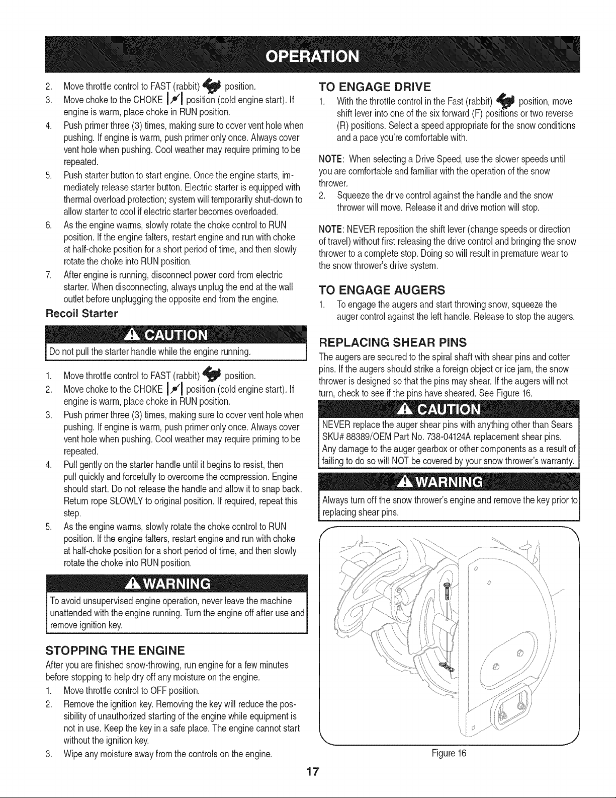
REPLACING SHEAR PINS
The augersare securedto the spiralshaftwith shearpins andcotter
pins.If the augersshouldstrikea foreignobjector ice jam,the snow
throweris designedso that the pins mayshear.If theaugerswill not
turn,checkto see if the pins havesheared.SeeFigure16.
NEVERreplacethe auger shearpinswithanythingotherthanSears
SKU#88389/0EMPart No. 738-04124Areplacementshearpins.
Anydamageto the augergearboxor othercomponentsas a resultof
[fa ng to doso w NOTbe coveredby yoursnow throwers warranty.
Alwaysturnoff the snowthrower'sengineandremovethe keyprior to
replacingshearpins.
o
iJ
Figure16
17
MAINTENANCE SCHEDULE
Beforeperforminganytypeof maintenance/service,disengageall
controlsand stoptheengine.Waituntilallmovingpartshavecometo
acompletestop.Disconnectsparkplugwireandgrounditagainstthe
enginetopreventunintendedstarting.Alwayswearsafetyglassesduring
operationor whileperforminganyadjustmentsor repairs.
Followthe maintenanceschedulegivenbelow.This chartdescribes
serviceguidelinesonly. Usethe ServiceLogcolumnto keeptrackof
completedmaintenancetasks.To locate the nearest Sears Service
Centeror to scheduleservice,simplycontactSears at
1-800-4-MY-HOME®.
EachUseandevery5
hours
1st5 hours
Annuallyor 25 hours
Annuallyor 50 hours
Annuallyor 100 hours
BeforeStorage
1. Engineoillevel
2. Looseormissinghardware
3. Unitandengine.
1. Engineoil
1. Sparkplug
2. Controllinkagesand pivots
3. Wheels
4. Gearshaft and Augershaft
5. 4-WayChuteControlTM
1. Engineoil
1. Sparkplug
1. Fuelsystem
1. Check
2. Tightenor replace
3. Clean
1. Change
1. Check
2. Lubewithlightoil
3. Lubewithmultipurposeautogrease
4. Lubewithlightoil
5. Checkfor cableslackness
1. Change
1. Change
1. Runengineuntilit stopsfromlack
of fuel
ENGINE MAINTENANCE
Beforelubricating,repairing,or inspecting,disengageall controls
Iandstop engine.Wait untilall movingpartshavecometo a complete
_stop.
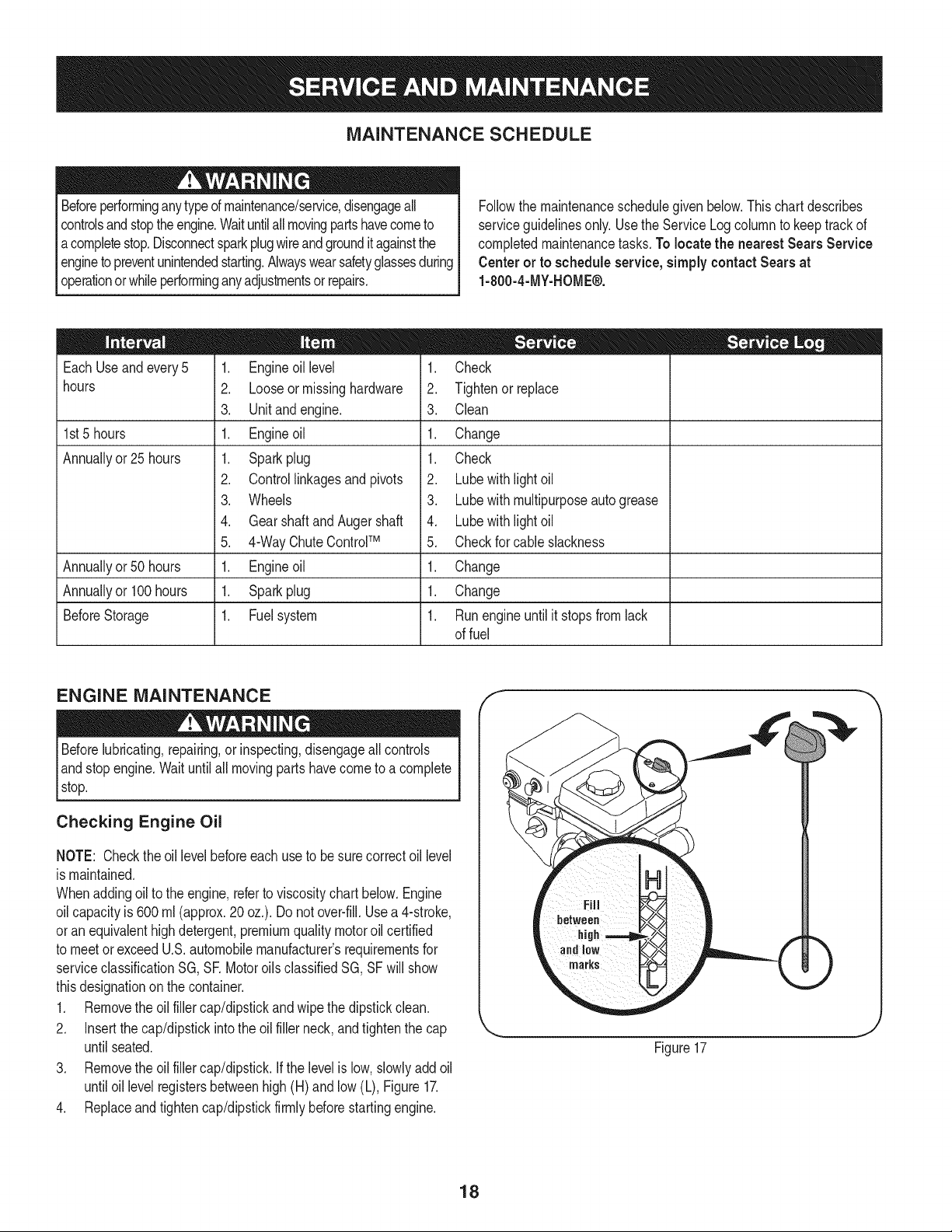
Checking Engine Oil
NOTE: Checktheoil levelbeforeeachuseto besurecorrectoil level
is maintained.
Whenaddingoilto the engine,referto viscositychart below.Engine
oilcapacityis 600 ml (approx.20 oz.). Donot over-fill.Usea 4-stroke,
oran equivalenthighdetergent,premiumquality motoroilcertified
to meetor exceedU.S.automobilemanufacturer'srequirementsfor
serviceclassificationSG, SR MotoroilsclassifiedSG, SFwill show
thisdesignationon the container.
1. Removethe oil fillercap/dipstickandwipethe dipstickclean.
2. Insertthe cap/dipstickintothe oil filler neck,andtightenthe cap
until seated.
3. Removethe oil fillercap/dipstick.Ifthe levelis low, slowlyadd oil
untiloil levelregistersbetweenhigh (H) and low(L), Figure17.
4. Replaceandtightencap/dipstickfirmlybeforestartingengine.
f
Figure17
18
Changing Engine Oil
NOTE:Changethe engineoil afterthe first 5 hoursof operationand
oncea seasonorevery 50hoursthereafter.
1. Drainfuelfromtank by runningengineuntilthe fuel tankis empty.
Besurefuel fill cap is secure.
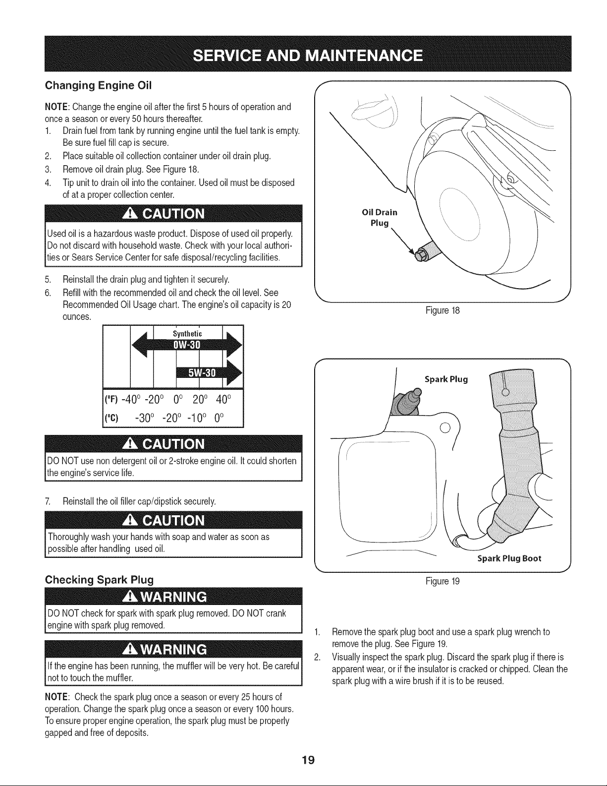
2. Placesuitableoil collectioncontainerunderoildrainplug.
3. Removeoildrain plug.SeeFigure18.
4. Tip unitto drain oil intothe container.Usedoil mustbe disposed
of at a propercollectioncenter.
Usedoil is a hazardouswasteproduct.Disposeof usedoil properly.
Donotdiscardwith householdwaste.Checkwith yourlocalauthori-
tiesor SearsServiceCenterfor safedisposal/recyclingfacilities.
.
6.
Reinstallthe drain plugandtightenit securely.
Refillwiththe recommendedoil andcheckthe oil level.See
RecommendedOil Usagechart.Theengine'soil capacityis 20
ounces.
u i
Synthetic
(0F)-40o-20 o 0o 200 400
("c) -30° -20 ° -10° 0°
DONOTuse nondetergentoil or 2-strokeengineoil. It couldshorten
the engine'sservicelife.
7. Reinstallthe oilfillercap/dipsticksecurely.
Thoroughlywashyour handswith soapandwater as soonas
possibleafterhandling usedoil.
Checking Spark Plug
Oil Drain
Plug
_=, ,J
Figure18
Spark Plug
©
Figure19
J
DO NOTcheckfor sparkwithspark plugremoved.DO NOTcrank
enginewithsparkplug removed.
Ifthe engine hasbeenrunning,the mufflerwill be very hot.Be careful
notto touchthe muffler.
NOTE: Checkthe sparkplugoncea seasonor every25 hoursof
operation.Changethe sparkplugoncea seasonor every 100hours.
Toensureproperengineoperation,the sparkplug mustbe properly
gappedandfreeof deposits.
1. Removethe sparkplugbootand usea spark plugwrenchto
removethe plug.SeeFigure19.
2. Visuallyinspectthe sparkplug. Discardthe sparkplugif thereis
apparentwear,or if the insulatoris crackedor chipped.Cleanthe
sparkplugwith awire brushif it is to be reused.
19
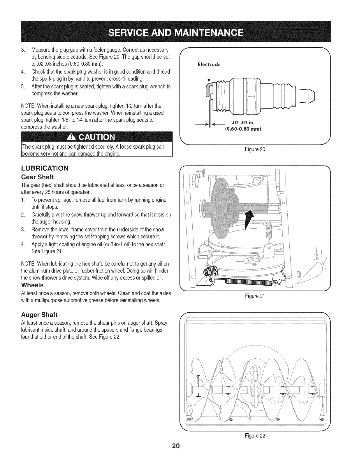
3. Measurethe pluggapwitha feelergauge.Correctas necessary
by bendingsideelectrode.See Figure20. Thegap shouldbe set
to .02-.03inches(0.60-0.80ram).
4. Checkthat thesparkplug washeris ingood conditionandthread
the sparkplugin by handto preventcross-threading.
5. Afterthe sparkplugis seated,tightenwitha sparkplugwrenchto
compressthe washer.
NOTE:Wheninstallinga newsparkplug,tighten 1/2-turnafter the
sparkplugseatsto compressthe washer.Whenreinstallinga used
sparkplug,tighten1/8-to 1/4-turnafter the sparkplugseatsto
compressthe washer.
hot andcan ine.
f
J
Figure20
LUBRICATION
Gear Shaft
Thegear(hex)shaft shouldbe lubricatedat least oncea seasonor
afterevery25 hoursof operation.
1. Topreventspillage,removeall fuel fromtank by runningengine
until it stops.
2. Carefullypivotthe snowthrowerupand forwardso that it restson
theaugerhousing.
3. Removethe lowerframecover fromthe undersideof the snow
throwerby removingthe self-tappingscrewswhich secureit.
4. Applya lightcoatingof engineoil (or 3-in-1oil) to the hexshaft.
SeeFigure21.
NOTE:Whenlubricatingthe hexshaft, be carefulnotto get any oilon
thealuminumdriveplateor rubberfrictionwheel. Doingsowill hinder
the snowthrower'sdrive system.Wipeoff anyexcessor spilledoil.
Wheels
At leastoncea season,removebothwheels.Cleanandcoattheaxles
witha multipurposeautomotivegreasebeforereinstallingwheels.
Figure21
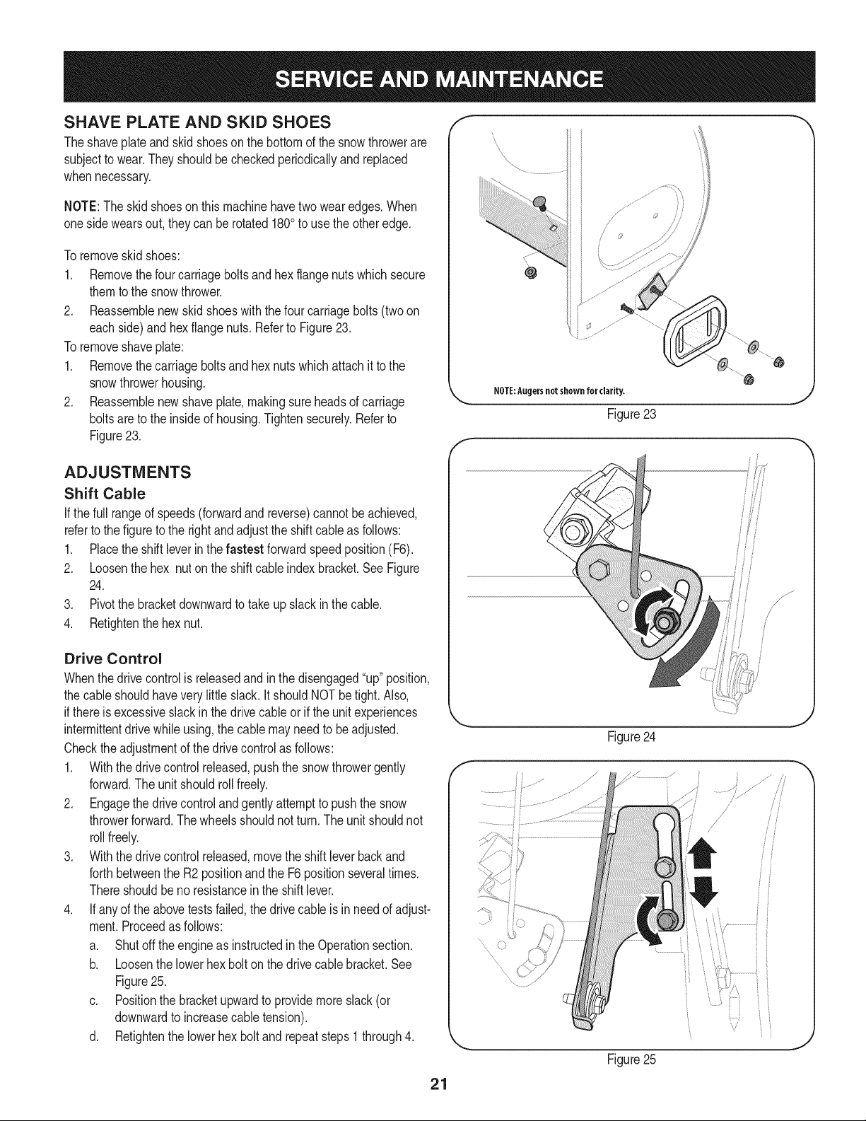
Auger Shaft
At leastoncea season,removethe shearpinson augershaft.Spray
lubricantinsideshaft,andaroundthe spacersandflangebearings
foundat eitherendof the shaft. SeeFigure22.
f
\
2O
Figure22
J
SHAVE PLATE AND SKiD SHOES
Theshaveplateand skidshoeson the bottomof the snowthrowerare
subjectto wear.They shouldbecheckedperiodicallyand replaced
whennecessary.
NOTE:Theskidshoes onthis machinehavetwo wearedges.When
onesidewearsout, theycan be rotated1800to usethe otheredge.
Toremoveskidshoes:
1. Removethefour carriageboltsand hexflangenutswhich secure
themtothe snowthrower.
2. Reassemblenew skid shoeswiththefour carriagebolts(two on
eachside)and hexflangenuts.Referto Figure23.
Toremoveshaveplate:
1. Removethecarriageboltsand hexnuts whichattachit to the
snowthrowerhousing.
2. Reassemblenew shaveplate,makingsureheadsof carriage
boltsare to the insideof housing.Tightensecurely.Referto
Figure23.
NOTE:Augersnotshown for clarity.
Figure23
ADJUSTMENTS
Shift Cable
If thefull rangeof speeds(forwardandreverse)cannotbe achieved,
referto the figureto the rightandadjustthe shift cableas follows:
1. Placethe shiftleverin thefastest forwardspeedposition(F6).
2. Loosenthe hex nuton the shiftcable indexbracket.See Figure
24.
3. Pivotthe bracketdownwardto takeup slack inthe cable.
4. Retightenthehex nut.
Drive Control
Whenthedrivecontrolisreleasedandin thedisengaged"up"position,
the cableshouldhavevery little slack.It shouldNOTbetight. Also,
ifthereisexcessiveslackin thedrive cableor if the unitexperiences
intermittentdrivewhileusing,the cable mayneed to beadjusted.
Checktheadjustmentof the drivecontrolas follows:
1. Withthedrivecontrol released,pushthe snowthrowergently
forward.The unitshouldroll freely.
2. Engagethe drivecontrolandgently attemptto pushthe snow
throwerforward.Thewheelsshouldnotturn.The unitshouldnot
rollfreely.
3. Withthedrivecontrolreleased,movethe shift leverbackand
forthbetweenthe R2positionand the F6 positionseveraltimes.
Thereshouldbeno resistancein the shiftlever.
4. If anyof the abovetestsfailed,the drivecable isin needof adjust-
ment.Proceedas follows:
a. Shutoff theengineas instructedinthe Operationsection.
b. Loosenthe lowerhexbolt onthe drivecable bracket.See
Figure25.
c. Positionthe bracketupwardto providemoreslack(or
downwardto increasecabletension).
d. Retightenthe lowerhex boltand repeatsteps1 through4.
21
f
Figure24
........
Figure25
fj
/
/
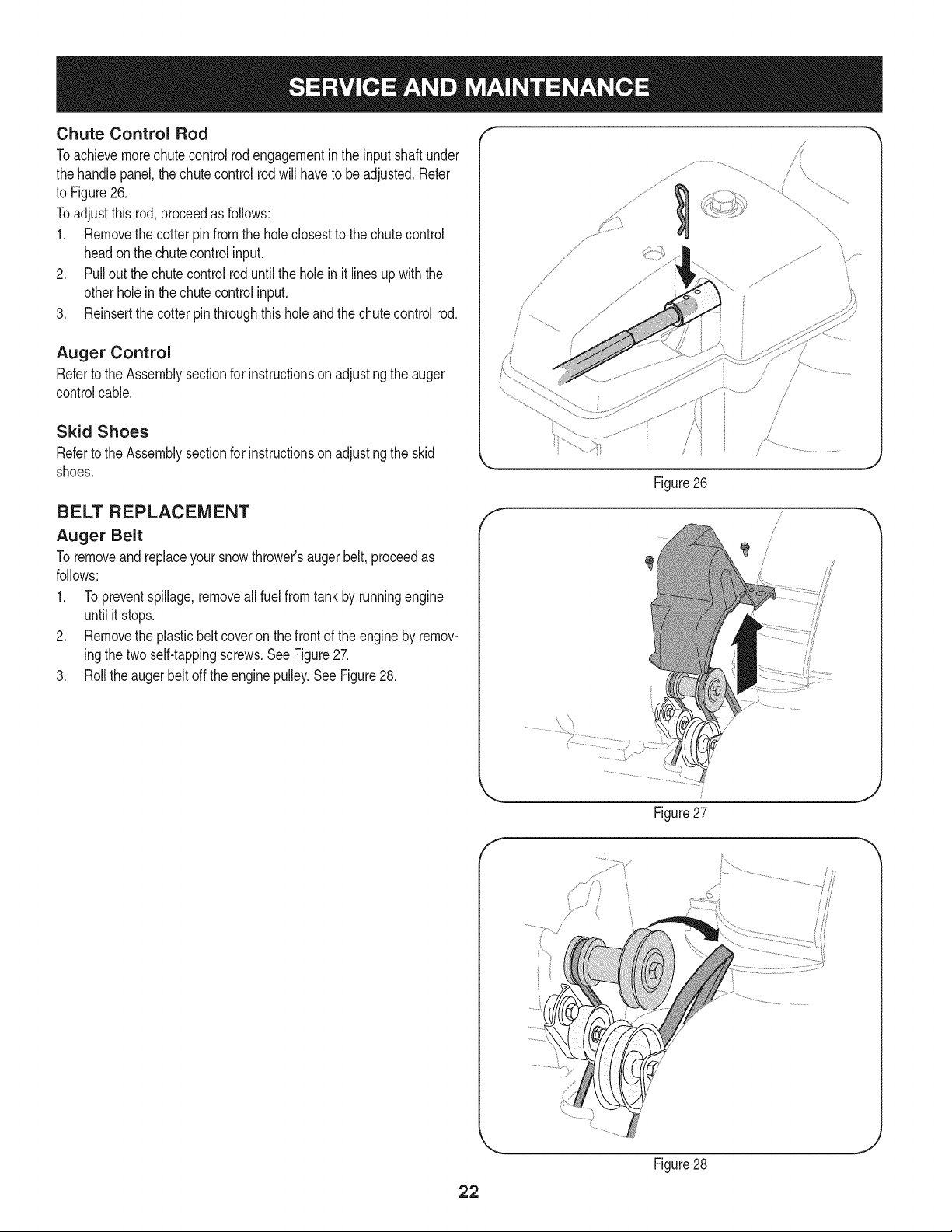
Chute Control Rod
Toachievemorechute controlrodengagementin the inputshaft under
the handlepanel,thechutecontrolrodwill haveto beadjusted.Refer
to Figure26.
Toadjustthis rod,proceedas follows:
1. Removethe cotter pinfromthe hole closestto the chutecontrol
headon the chutecontrolinput.
2. Pullout thechutecontrolrod until theholein it linesup withthe
otherholein thechute controlinput.
3. Reinsertthe cotterpinthroughthis holeandthe chutecontrolrod.
Auger Control
Referto the Assemblysectionfor instructionson adjustingtheauger
controlcable.
Skid Shoes
Referto the Assemblysectionfor instructionson adjustingthe skid
shoes.
BELT REPLACEMENT
Auger Belt
To removeandreplaceyoursnowthrower'sauger belt,proceedas
follows:
1. Topreventspillage,removeall fuel fromtank by runningengine
until it stops.
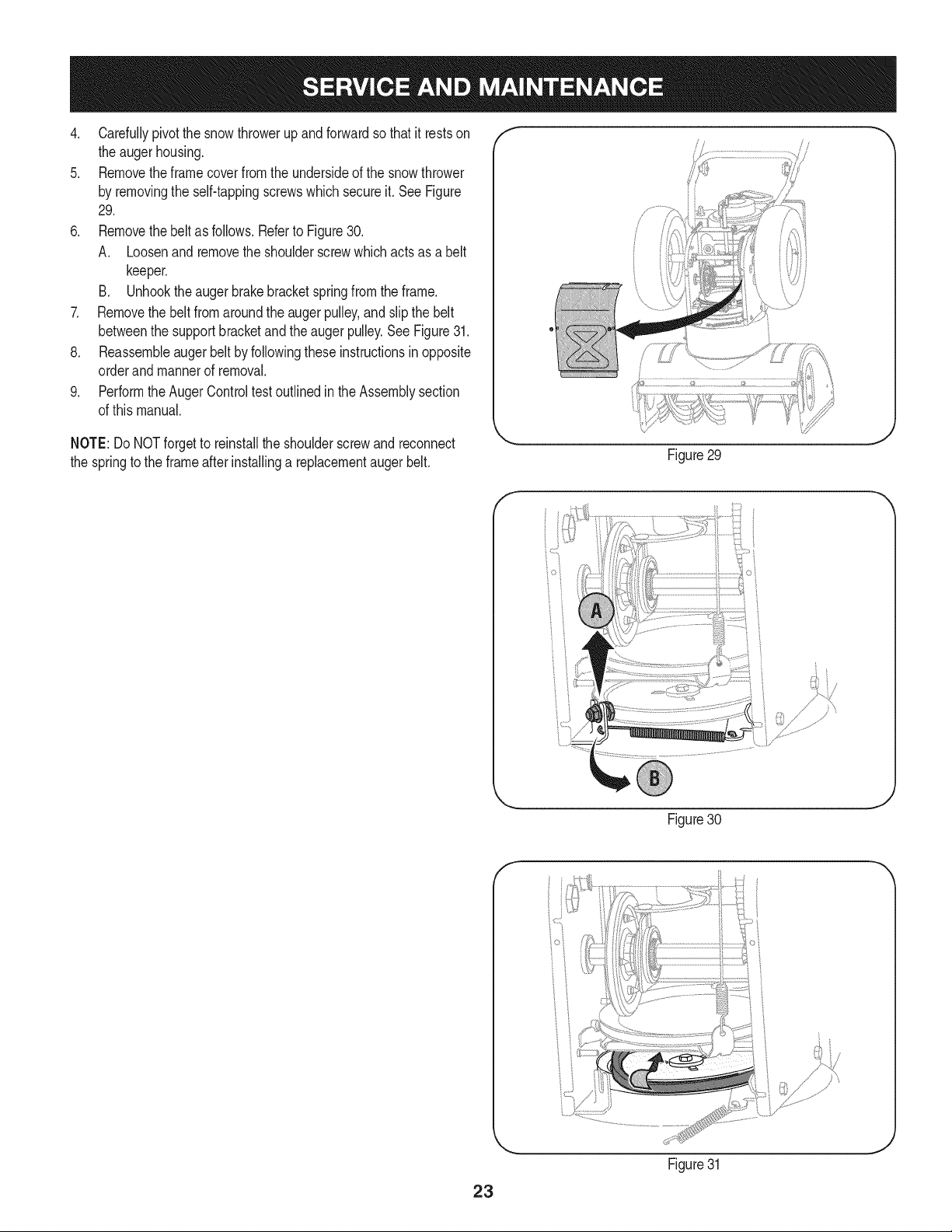
2. Removethe plasticbelt coveron the frontof the engineby remov-
ingthe two self-tappingscrews.See Figure27.
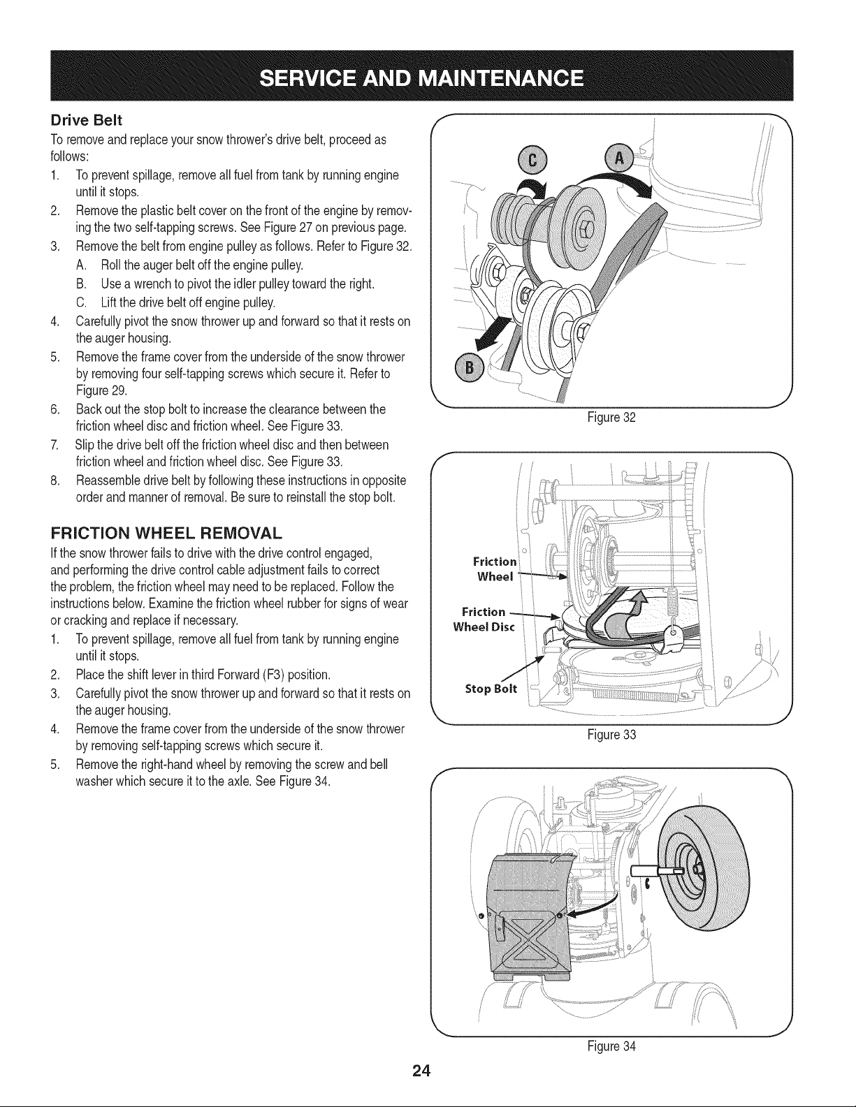
3. Rollthe auger beltoff theenginepulley.See Figure28.
f
/
/
/
/
/
/
Figure26
f
Figure27
J
/
22
Figure28
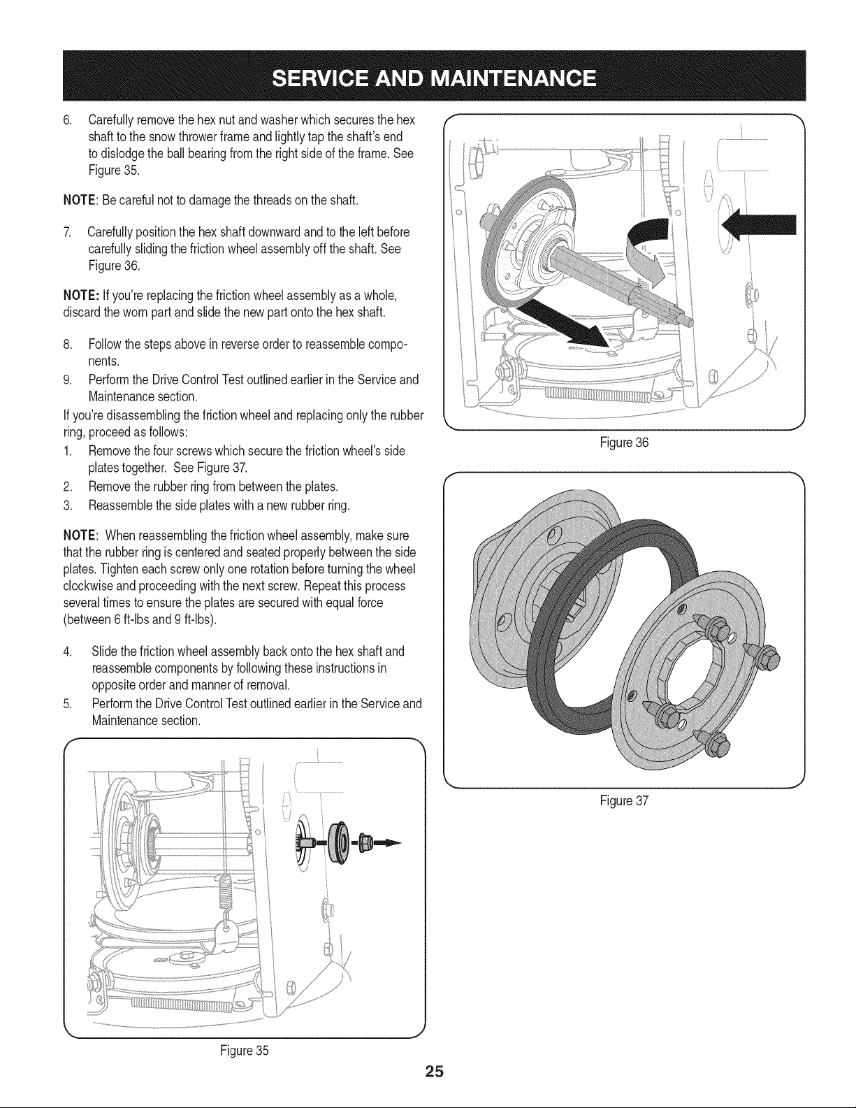
4. Carefullypivotthesnowthrowerupandforwardsothatitrestson
theaugerhousing.
5. Removetheframecoverfromtheundersideofthesnowthrower
byremovingtheself-tappingscrewswhichsecureit.SeeFigure
29.
6. Removethebeltasfollows.RefertoFigure30.
A. Loosenandremovetheshoulderscrewwhichactsasabelt
keeper.
B. Unhooktheaugerbrakebracketspringfromtheframe.
7. Removethebeltfromaroundtheaugerpulley,andslipthebelt
betweenthesupportbracketandtheaugerpulley.SeeFigure31.
8. Reassembleaugerbeltbyfollowingtheseinstructionsinopposite
orderandmannerofremoval.
9. PerformtheAugerControltestoutlinedintheAssemblysection
ofthismanual.
/
NOTE:Do NOTforgetto reinstallthe shoulderscrewand reconnect
the springto the frame afterinstallinga replacementaugerbelt.
Figure29
f
Figure30
f
23
Figure31
Drive Belt
To removeandreplaceyoursnowthrower'sdrivebelt, proceedas
follows:
1. Topreventspillage,removeall fuel fromtank by runningengine
until it stops.
2. Removethe plasticbelt coveron the frontof the engineby remov-
ingthe two self-tappingscrews.See Figure27 on previouspage.
3. Removethe beltfromenginepulleyas follows.Referto Figure32.
A. Rollthe augerbeltoff theengine pulley.
B. Usea wrenchto pivotthe idler pulleytowardthe right.
C. Liftthe drivebelt offengine pulley.
4. Carefullypivotthe snowthrowerup and forwardsothat it restson
the augerhousing.
5. Removethe framecoverfromthe undersideof thesnowthrower
by removingfour self-tappingscrewswhich secureit. Referto
Figure29.
6. Backoutthe stopbolt to increasethe clearancebetweenthe
frictionwheeldiscand frictionwheel.SeeFigure33.
7. Slipthe drivebelt off the frictionwheeldiscand thenbetween
frictionwheelandfrictionwheeldisc.See Figure33.
8. Reassembledrive beltby followingthese instructionsin opposite
orderand mannerof removal.Besureto reinstallthe stopbolt.
FRICTION WHEEL REMOVAL
Ifthe snowthrowerfailsto drive with thedrivecontrolengaged,
andperformingthe drivecontrolcableadjustmentfails to correct
the problem,the frictionwheelmayneedto be replaced.Followthe
instructionsbelow.Examinethe frictionwheelrubberfor signsof wear
orcrackingand replaceif necessary.
1. Topreventspillage,removeall fuel fromtank by runningengine
until it stops.
2. Placethe shiftleverin third Forward(F3) position.
3. Carefullypivotthe snowthrowerupand forwardso that it restson
theaugerhousing.
4. Removethe framecoverfrom the undersideof the snow thrower
by removingself-tappingscrewswhich secureit.
5. Removethe right-handwheelby removingthe screwandbell
washerwhichsecureit to theaxle.See Figure34.
Figure32
J
Friction
Wheel
Friction
WheelDisci i
Figure33
f
Figure34
J
24
.
Carefullyremovethe hexnut and washerwhichsecuresthehex
shaftto the snowthrowerframeand lightlytap the shaft'send _;!
to dislodgethe ball bearingfromthe rightsideof the frame.See
Figure35. .]_j
NOTE:Becarefulnot to damagethe threadson the shaft.
7. Carefullypositionthe hexshaftdownwardand to the left before
carefullyslidingthe frictionwheelassemblyoff the shaft.See
Figure36.
NOTE: Ifyou'rereplacingthe frictionwheelassemblyas a whole,
discardthe wornpartand slidethe newpart ontothe hexshaft.
8. Followthe stepsabovein reverseorderto reassemblecompo-
nents.
9. Performthe DriveControlTestoutlinedearlier inthe Serviceand
Maintenancesection.
If you'redisassemblingthefrictionwheeland replacingonly the rubber
ring,proceedas follows:
1. Removethefour screwswhich securethe frictionwheel'sside
platestogether. SeeFigure37.
2. Removethe rubberringfrom betweenthe plates.
3. Reassemblethe side plateswith a newrubberring.
Figure36
NOTE: Whenreassemblingthe frictionwheelassembly,makesure
thatthe rubberring is centeredand seatedproperlybetweenthe side
plates.Tighteneachscrewonlyone rotationbeforeturningthe wheel
clockwiseand proceedingwith the nextscrew.Repeatthis process
severaltimes toensurethe platesaresecuredwith equalforce
(between6 ft-lbsand 9 ft-lbs).
4. Slide the frictionwheelassemblybackonto the hexshaftand
reassemblecomponentsby followingthese instructionsin
oppositeorderand mannerof removal.
5. Performthe DriveControlTestoutlinedearlierin the Serviceand
Maintenancesection.
f
Figure35
Figure37
J
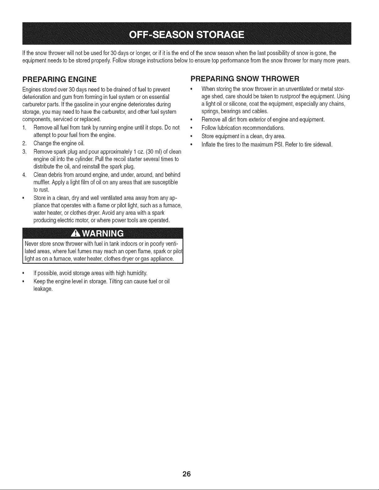
Ifthesnowthrowerwillnotbeusedfor30daysorlonger,orifitistheendofthesnowseasonwhenthelastpossibilityofsnowisgone,the
equipmentneedstobestoredproperly.Followstorageinstructionsbelowtoensuretopperformancefromthesnowthrowerformanymoreyears.
PREPARING ENGINE
Enginesstoredover30 daysneed to bedrainedof fuel to prevent
deteriorationandgumfrom forminginfuel systemor onessential
carburetorparts.If thegasolineinyourenginedeterioratesduring
storage,youmay needto havethe carburetor,andotherfuel system
components,servicedor replaced.
1. Removeall fuel fromtank by runningengineuntil it stops.Donot
attemptto pourfuel fromthe engine.
2. Changethe engineoil.
3. Removesparkplugand pourapproximately1 oz.(30 rnl) of clean
engineoil intothe cylinder.Pullthe recoilstarterseveraltimesto
distributetheoil, and reinstallthe spark plug.
4. Cleandebrisfromaroundengine,and under,around,andbehind
muffler.Applya lightfilmof oil on anyareasthatare susceptible
to rust.
• Storeina clean,dry and wellventilatedarea awayfromanyap-
pliancethat operateswitha flameor pilotlight, suchas a furnace,
waterheater,or clothesdryer.Avoidany areawith a spark
producingelectricmotor,or wherepowertools areoperated.
Neverstoresnowthrowerwith fuel intank indoorsor inpoorlyventi-
latedareas,wherefuel fumesmay reachan openflame,sparkor pilol
lightas ona furnace,waterheater,clothesdryer orgas appliance.
• If possible,avoidstorageareaswith highhumidity.
• Keepthe enginelevelin storage.Tiltingcan causefuel oroil
leakage.
PREPARING SNOW THROWER
Whenstoringthe snowthrowerin anunventilatedormetalstor-
age shed,careshouldbetaken to rustprooftheequipment.Using
a light oilor silicone,coattheequipment,especiallyanychains,
springs,bearingsand cables.
• Removealldirt fromexteriorof engineandequipment.
• Followlubricationrecommendations.
• Storeequipmentin a clean,dry area.
• Inflatethe tiresto the maximumPSi. Referto tiresidewall.
26
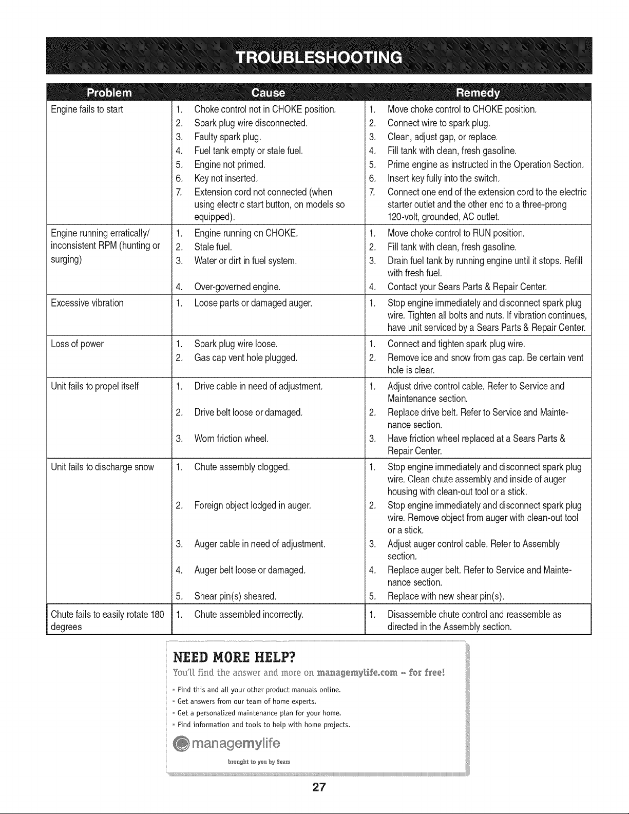
Enginefailsto start
Enginerunningerratically/
inconsistentRPM(huntingor
surging)
Excessivevibration
Lossof power
Unitfailsto propel itself
Unitfailsto dischargesnow
1. Chokecontrolnot in CHOKEposition.
2. Sparkplugwire disconnected.
3. Faultysparkplug.
4. Fueltankemptyor stalefuel.
5. Enginenot primed.
6. Keynot inserted.
7. Extensioncordnot connected(when
usingelectricstartbutton,on modelsso
equipped).
1. EnginerunningonCHOKE.
2. Stalefuel.
3. Waterordirt infuel system.
4. Over-governedengine.
1. Loosepartsor damagedauger.
1. Sparkplugwire loose.
2. Gascap vent holeplugged.
1. Drivecable in needof adjustment.
2. Drivebelt looseor damaged.
3. Wornfrictionwheel.
1. Chuteassemblyclogged.
2. Foreignobjectlodgedin auger.
3. Augercablein needof adjustment.
4. Augerbelt looseordamaged.
5. Shearpin(s) sheared.
1. Chuteassembledincorrectly.
1. Movechokecontrolto CHOKEposition.
2. Connectwireto sparkplug.
3. Clean,adjustgap,or replace.
4. Filltankwith clean,freshgasoline.
5. Primeengineas instructedin the OperationSection.
6. Insertkeyfully intothe switch.
7. Connectoneend of the extensioncordto the electric
starteroutletandthe otherend to a three-prong
120-volt,grounded,ACoutlet.
1. Movechokecontrolto RUNposition.
2. Filltankwith clean,freshgasoline.
3. Drainfueltankby runningengineuntil it stops.Refill
withfreshfuel.
4. ContactyourSearsParts& RepairCenter.
1. Stopengineimmediatelyand disconnectsparkplug
wire.Tightenall boltsand nuts.Ifvibrationcontinues,
haveunit servicedbya SearsParts& RepairCenter.
1. Connectandtightenspark plugwire.
2. Removeiceand snowfromgascap. Be certainvent
holeis clear.
1. Adjustdrivecontrolcable.Referto Serviceand
Maintenancesection.
2. Replacedrive belt.Referto Serviceand Mainte-
nancesection.
3. Havefrictionwheelreplacedat a SearsParts&
RepairCenter.
1. Stopengineimmediatelyand disconnectsparkplug
wire.Cleanchuteassemblyand insideof auger
housingwith clean-outtoolor a stick.
2. Stopengineimmediatelyand disconnectsparkplug
wire.Removeobjectfromaugerwith clean-outtool
ora stick.
3. Adjustaugercontrolcable.Referto Assembly
section.
4. Replaceaugerbelt.Referto Serviceand Mainte-
nancesection.
5. Replacewith newshearpin(s).
Chutefailsto easily rotate180 1. Disassemblechutecontroland reassembleas
degrees directedinthe Assemblysection.
NEED HORE HELP?
Yot,Fttfind. th_ answer a!ld mo_e on ma_age_y_ifeocom _ for free]
Find this and att your other product manua[s ontine.
Get answers from our team of home experts.
Get a personalized maintenance p[an for your home.
Find information and tools to he[p with home projects.
managemylife
b_e'_g_t_/_eyeu by Sea_s
27
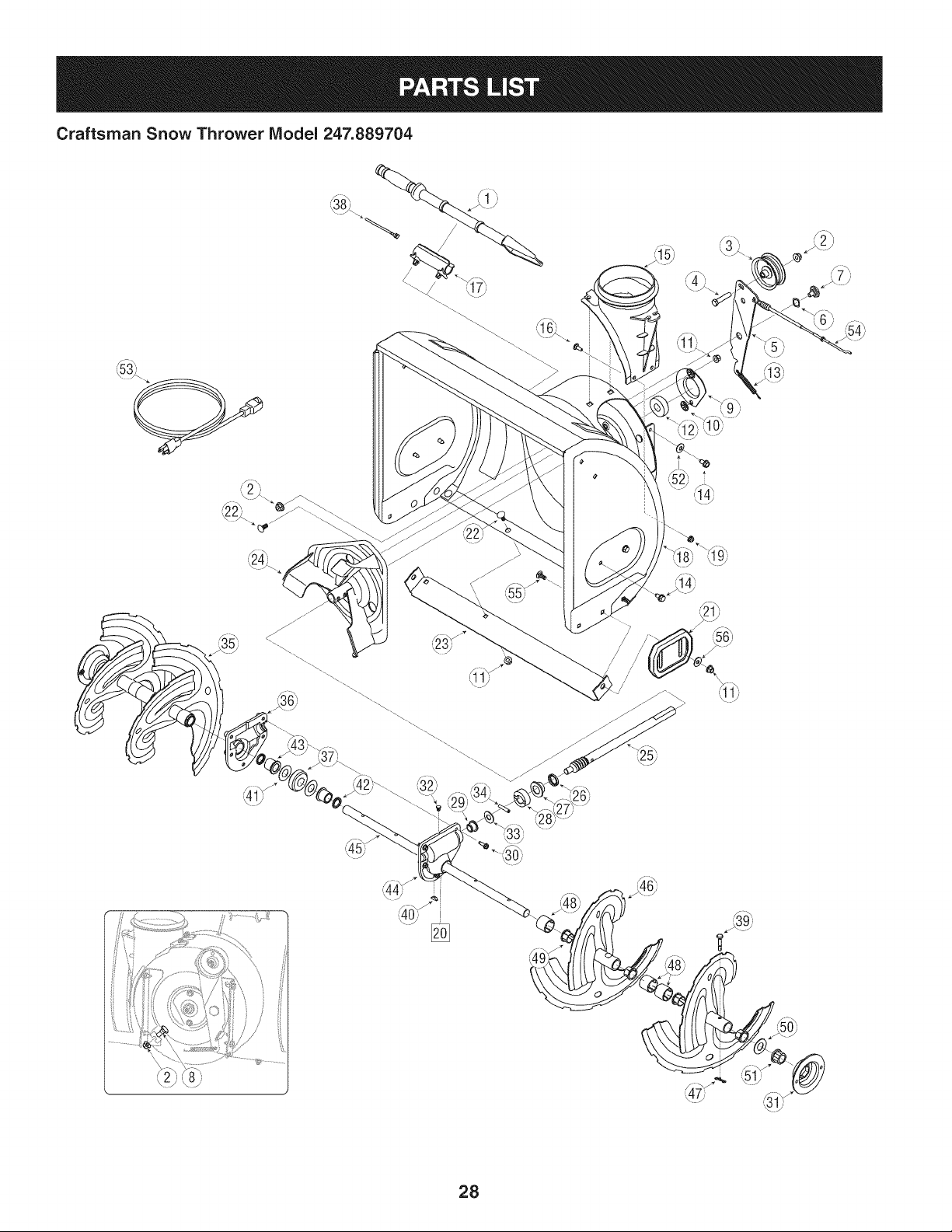
Craftsman Snow Thrower Model 247.889704
t
i )
_39_
- _' ',_1;f
28
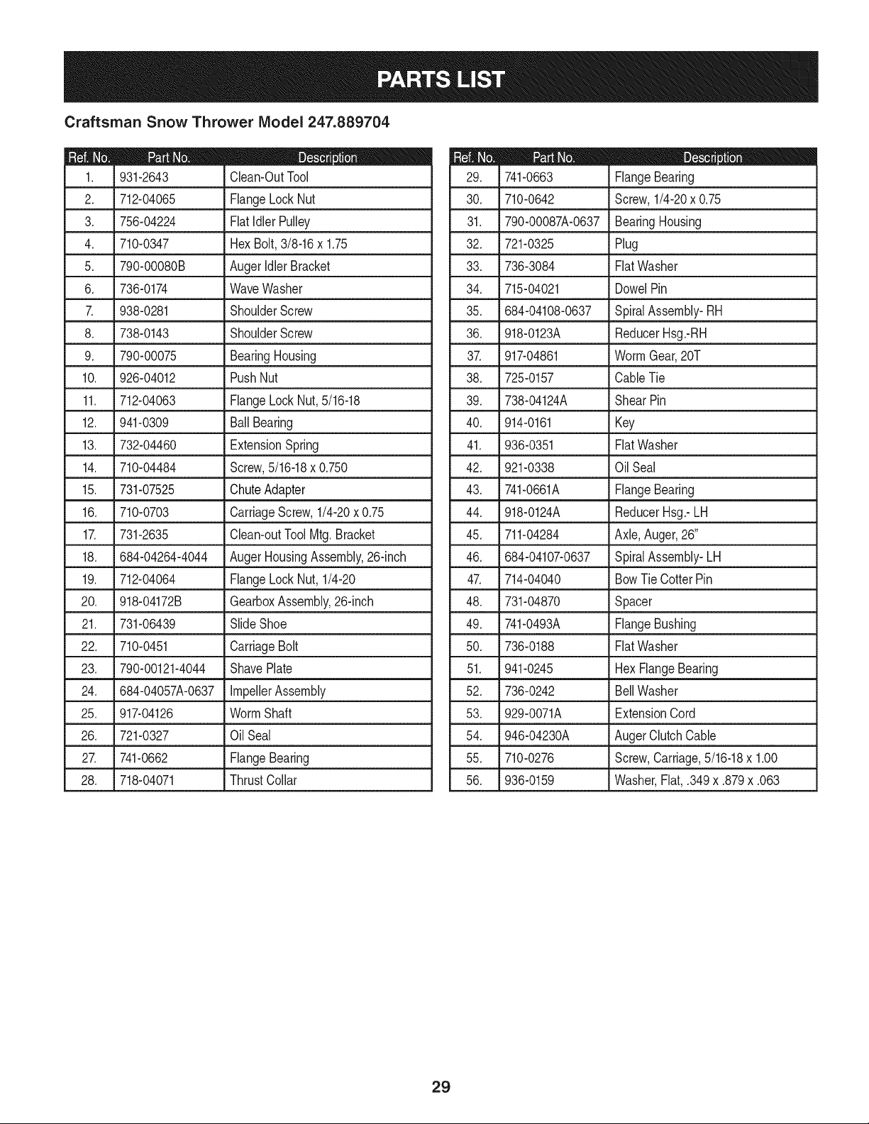
Craftsman Snow Thrower IViodel 247.889704
D = 0
931-2643 Clean-OutTool
2. 712-04065 FlangeLockNut
3. 756-04224 Fiatidler Pulley
4. 710-0347 HexBolt,3/8-16x 1.75
5. 790-00080B AugerIdlerBracket
6. 736-0174 WaveWasher
7. 938-0281 ShoulderScrew
8. 738-0143 ShoulderScrew
9. 790-00075 BearingHousing
10. 926-04012 PushNut
11. 712-04063 FlangeLockNut,5/16-18
12. 941-0309 Ball Bearing
13. 732-04460 ExtensionSpring
14. 710-04484 Screw,5/16-18x 0.750
15. J731-07525 J ChuteAdapter
16. 710-0703 CarriageScrew,1/4-20x 0.75
17. 731-2635 Clean-outToolMtg.Bracket
18. 684-04264-4044 AugerHousingAssembly,26-inch
19. 712-04064 FlangeLockNut, 1/4-20
20. 918-04172B GearboxAssembly,26-inch
21. 731-06439 SlideShoe
22. 710-0451 CarriageBolt
23. 790-00121-4044 ShavePlate
24. 684-04057A-0637 ImpellerAssembly
25. 917-04126 WormShaft
26. 721-0327 Oil Seal
27. 741-0662 FlangeBearing
28. 718-04071 ThrustCollar
D = B
741-0663 FlangeBearing
30. 710-0642 Screw,1/4-20x 0.75
31. 790-00087A-0637 BearingHousing
32. 721-0325 Plug
33. 736-3084 Fiat Washer
34. 715-04021 DowelPin
35. 684-04108-0637 SpiralAssembly-RH
36. 918-0123A ReducerHsg.-RH
37. 917-04861 WormGear,20T
38. 725-0157 CableTie
39. 738-04124A ShearPin
40. 914-0161 Key
41. 936-0351 Fiat Washer
42. 921-0338 Oil Seal
43. 741-0661A FlangeBearing
44. 918-0124A ReducerHsg.-LH
45. 711-04284 Axle,Auger,26"
46. 684-04107-0637 SpiralAssembly-LH
47. 714-04040 BowTie CotterPin
48. 731-04870 Spacer
49. 741-0493A FlangeBushing
50. 736-0188 Fiat Washer
51. 941-0245 Hex FlangeBearing
52. 736-0242 Bell Washer
53. 929-0071A ExtensionCord
54. 946-04230A AugerClutchCable
55. 710-0276 Screw,Carriage,5/16-18x 1.00
56. 936-0159 Washer,Fiat, .349x .879x .063
29
Craftsman Snow Thrower IViodel 247.889704
_'.'X
'J2_\
=
<
......................................................,_!:...........................¢o_......................
3O
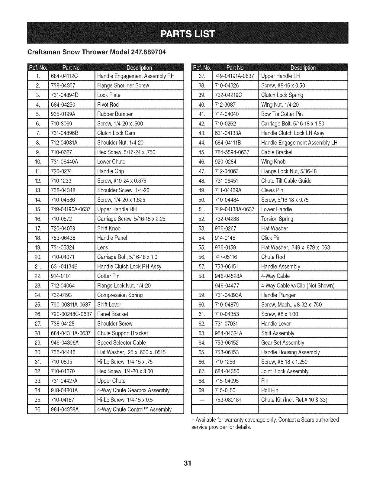
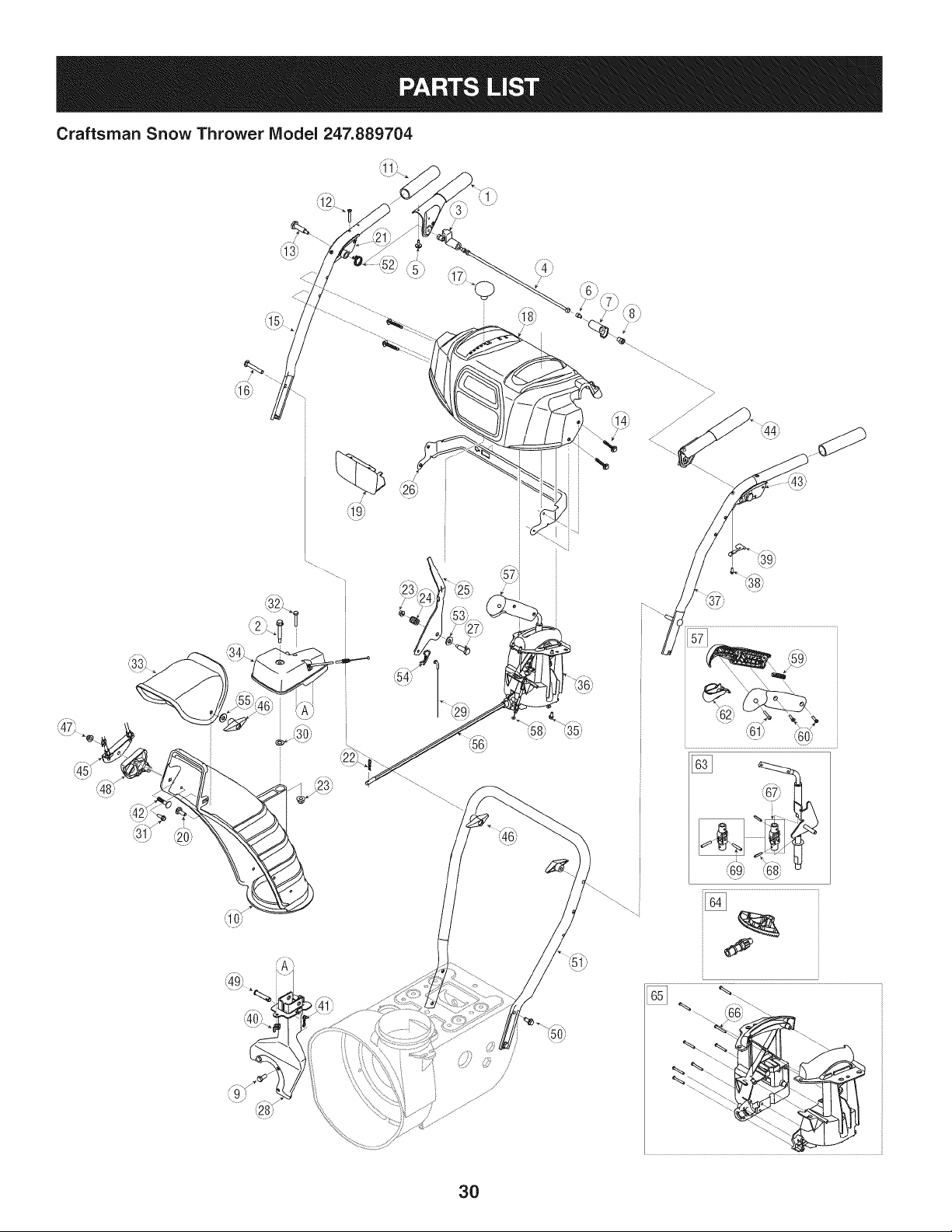
Craftsman Snow Thrower Model 247.889704
D = 0 0
684-04112C HandleEngagementAssemblyRH
2. _ 738-04367 _FlangeShoulderScrew
3. 731-04894D LockPlate
4. 684-04250 PivotRod
5. 935-0199A RubberBumper
6. 710-3069 Screw,1/4-20x .500
7. 731-04896B ClutchLockCam
8. 712-04081A ShoulderNut, 1/4-20
9. 710-0627 HexScrew,5/16-24x .750
10. 731-06440A LowerChute
11. 720-0274 HandleGrip
12. 710-1233 Screw,#10-24x 0.375
13. 738-04348 ShoulderScrew,1/4-20
14. 710-04586 Screw,1/4-20x 1.625
15. 749-04190A-0637 UpperHandleRH
16. 710-0572 CarriageScrew,5/16-18x 2.25
17. 720-04039 ShiftKnob
18. 753-06438 HandlePanel
19. 731-05324 Lens
20. 710-04071 CarriageBolt,5/16-18x 1.0
21. 631-04134B HandleClutchLockRH Assy
22. 914-0101 CotterPin
23. 712-04064 FlangeLockNut, 1/4-20
24. 732-0193 CompressionSpring
25. 790-00311A-0637 ShiftLever
26. 790-00248C-0637 PanelBracket
27. 738-04125 ShoulderScrew
28. 684-04311A-0637 ChuteSupportBracket
29. 946-04396A SpeedSelectorCable
30. 736-04446 FiatWasher,.25 x .630x .0515
31. 710-0895 Hi-LoScrew,1/4-15x .75
32. 710-04370 HexScrew,1/4-20x 3.00
33. 731-04427A UpperChute
34. _ 918-04801A _4-WayChute GearboxAssembly
35. 710-04187 Hi-LoScrew,1/4-15x 0.5
36. 984-04338A 4-WayChuteControlTM Assembly
D = O
749-04191A-0637 UpperHandleLH
38. 710-04326 Screw,#8-16x 0.50
39. 732-04219C ClutchLockSpring
40. 712-3087 WingNut, 1/4-20
41. 714-04040 BowTie CotterPin
42. 710-0262 CarriageBolt, 5/16-18x 1.50
43. 631-04133A HandleClutchLockLHAssy
44. 684-04111B HandleEngagementAssemblyLH
45. 784-5594-0637 CableBracket
46. 920-0284 WingKnob
47. 712-04063 FlangeLockNut,5/16-18
48. 731-06451 ChuteTiltCableGuide
49. 711-04469A ClevisPin
50. 710-04484 Screw,5/16-18x 0.75
51. 749-04138A-0637 LowerHandle
52. 732-04238 TorsionSpring
53. 936-0267 FiatWasher
54. 914-0145 ClickPin
55. 936-0159 FiatWasher,.349x .879x .063
56. 747-05116 ChuteRod
57. 753-06151 HandleAssembly
58. 946-04528A 4-WayCable
946-04477 4-WayCablew/Clip (NotShown)
59. 731-04893A HandlePlunger
60. 710-04879 Screw,Mach.,#8-32 x .750
61. 710-04353 Screw,#8 x 1.00
62. 731-07031 HandleLever
63. 984-04324A ShiftAssembly
64. 753-06152 GearSet Assembly
65. 753-06153 HandleHousingAssembly
66. 710-1256 Screw,#8-18x 1.250
67. 684-04350 JointBlockAssembly
68. 715-04095 Pin
69. 715-0150 Roll Pin
-- 753-080181- ChuteKit (Incl. Ref.#10& 33)
1-Availablefor warrantycoverageonly.Contacta Searsauthorized
serviceproviderfor details.
31
Craftsman Snow Thrower Model 247.889704
i,73/
<
32
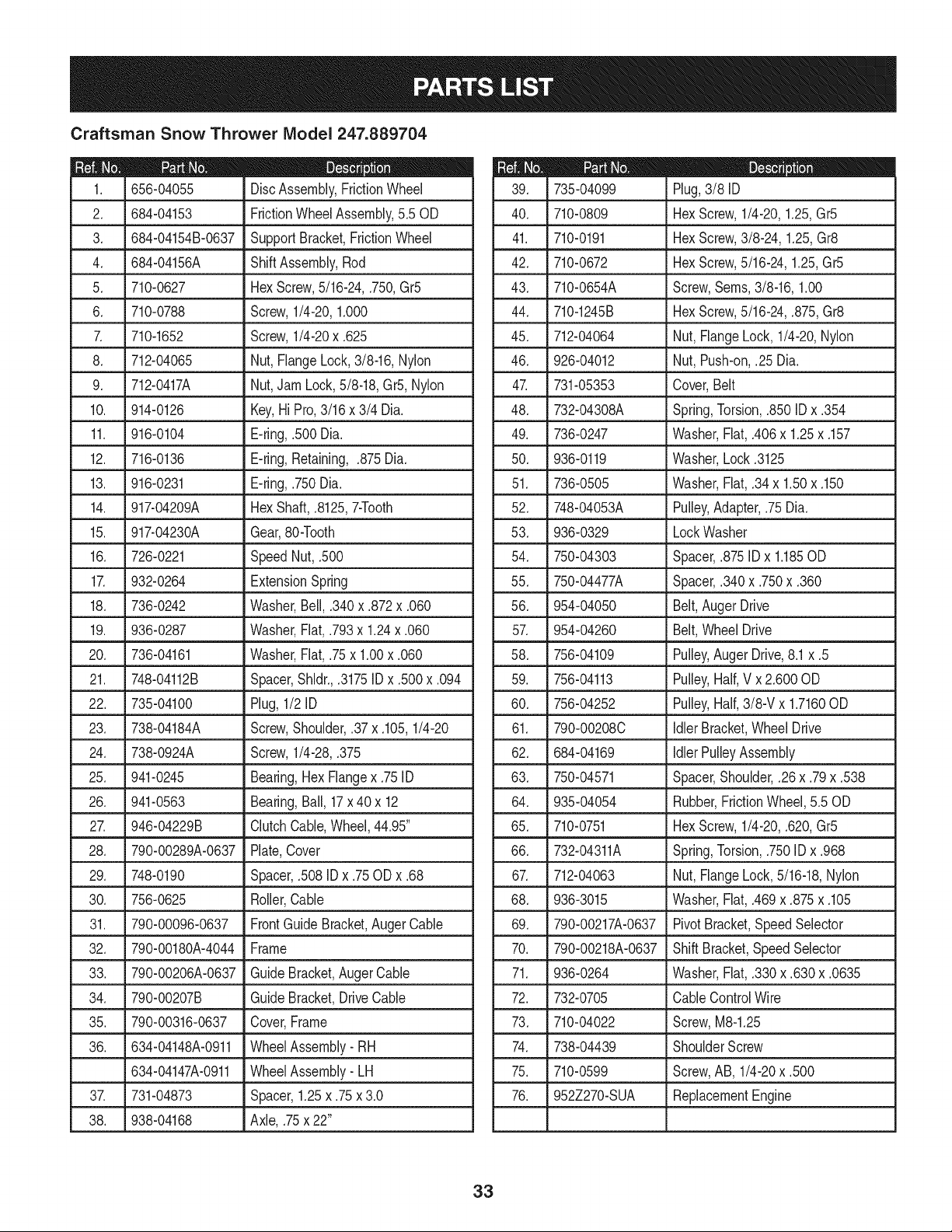
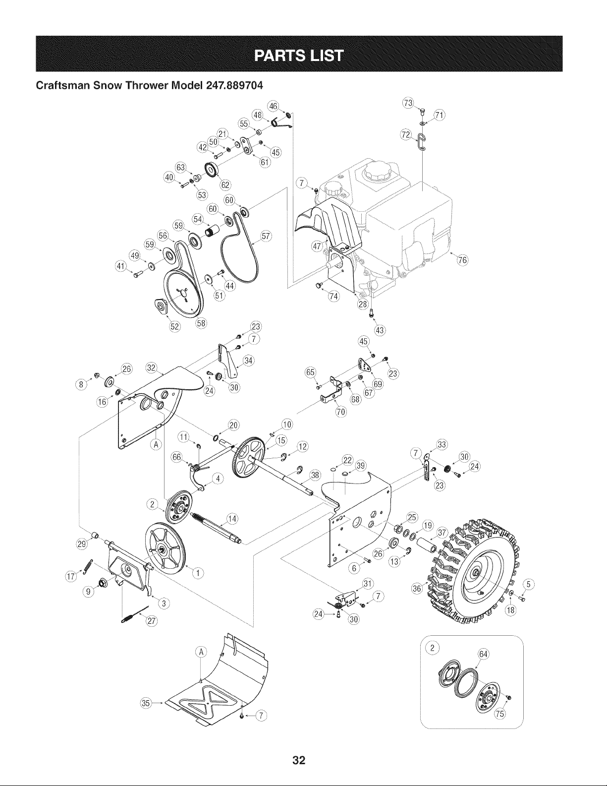
Craftsman Snow Thrower IViodel 247.889704
|= 0 =
656-04055 DiscAssembly,FrictionWheel
2. 684-04153 FrictionWheelAssembly,5.50D
3_ L684-04154B-0637_Supp°rt Bracket,Friction Wheel
4. 684-04156A Shift Assembly,Rod
5. 710-0627 HexScrew,5/16-24,.750,Gr5
6. 710-0788 Screw,1/4-20,1.000
7. 710-1652 Screw,1/4-20x .625
8. 712-04065 Nut,FlangeLock,3/8-16,Nylon
9. 712-0417A Nut,JamLock,5/8-18,Gr5,Nylon
10. 914-0126 Key,Hi Pro,3/16x 3/4 Dia.
11. 916-0104 E-ring,.500 Dia.
12. 716-0136 E-ring,Retaining, .875Dia.
13. 916-0231 E-ring,.750Dia.
14. 917-04209A HexShaft,.8125,7-Tooth
15. 917-04230A Gear,80-Tooth
16. 726-0221 SpeedNut, .500
17. 932-0264 ExtensionSpring
18. 736-0242 Washer,Bell, .340x .872x .060
19. .936-0287 Washer, Flat,.793x 1.24x .060
20. 736-04161 Washer,Flat,.75x 1.00x .060
21. 748-04112B Spacer,Shldr.,.3175ID x .500x .094
22. 735-04100 Plug,1/2 ID
23. 738-04184A Screw,Shoulder,.37 x .105,1/4-20
24. 738-0924A Screw,1/4-28,.375
25. 941-0245 Bearing,Hex Flangex .75ID
26. 941-0563 Bearing,Ball, 17x 40 x 12
27. ,946-04229B _ClutchCable,Wheel,44.95"
28. 790-00289A-0637 Plate,Cover
29. 748-0190 Spacer,.508 IDx .75ODx .68
30. 756-0625 Roller,Cable
31. 790-00096-0637 FrontGuideBracket,AugerCable
32. 790-00180A-4044 Frame
33. 790-00206A-0637 GuideBracket,AugerCable
34. 790-00207B GuideBracket,DriveCable
35. 790-00316-0637 Cover,Frame
36. 634-04148A-0911 WheelAssembly- RH
634-04147A-0911 WheelAssembly- LH
37. 731-04873 Spacer,1.25x .75x 3.0
38. 938-04168 Axle,.75x 22"
D = O O
735-04099 Plug,3/8 ID
40. 710-0809 HexScrew,1/4-20,1.25,Gr5
41. 710-0191 HexScrew,3/8-24,1.25,Gr8
42. 710-0672 HexScrew,5/16-24,1.25,Gr5
43. 710-0654A Screw,Seres,3/8-16,1.00
44. 710-1245B HexScrew,5/16-24,.875,Gr8
45. 712-04064 Nut, FlangeLock, 1/4-20,Nylon
46. 926-04012 Nut, Push-on,.25 Dia.
47. 731-05353 Cover,Belt
48. 732-04308A Spring,Torsion,.850 ID x .354
49. 736-0247 Washer,Flat,.406x 1.25x .157
50. 936-0119 Washer,Lock .3125
51. 736-0505 Washer,Flat,.34x 1.50x .150
52. 748-04053A Pulley,Adapter,.75Dia.
53. 936-0329 LockWasher
54. 750-04303 Spacer,.875IDx 1.185OD
55. 750-04477A Spacer,.340x .750x .360
56. 954-04050 Belt,Auger Drive
57. 954-04260 Belt,WheelDrive
58. 756-04109
59. 756-04113
60. 756-04252
61. 790-00208C
62. 684-04169
63. 750-04571
64. 935-04054
65. 710-0751
Pulley,AugerDrive,8.1x .5
Pulley,Half,V x 2.600OD
Pulley,Half,3/8-V x 1.7160OD
Idler Bracket,WheelDrive
Idler PulleyAssembly
Spacer,Shoulder,.26x .79x .538
Rubber,FrictionWheel, 5.50D
HexScrew,1/4-20,.620, Gr5
66. 732-04311A
67. 712-04063
68. 936-3015
69. 790-00217A-0637
70. 790-00218A-0637
71. 936-0264
72. 732-0705
73. 710-04022
Spring,Torsion,.750ID x .968
Nut, FlangeLock,5/16-18,Nylon
Washer,Flat,.469x .875x .105
PivotBracket,SpeedSelector
ShiftBracket,SpeedSelector
Washer,Fiat,.330x .630x .0635
CableControlWire
Screw,M8-1.25
74. 738-04439 ShoulderScrew
75. 710-0599 Screw,AB, 1/4-20x .500
76. 952Z270-SUA ReplacementEngine
33
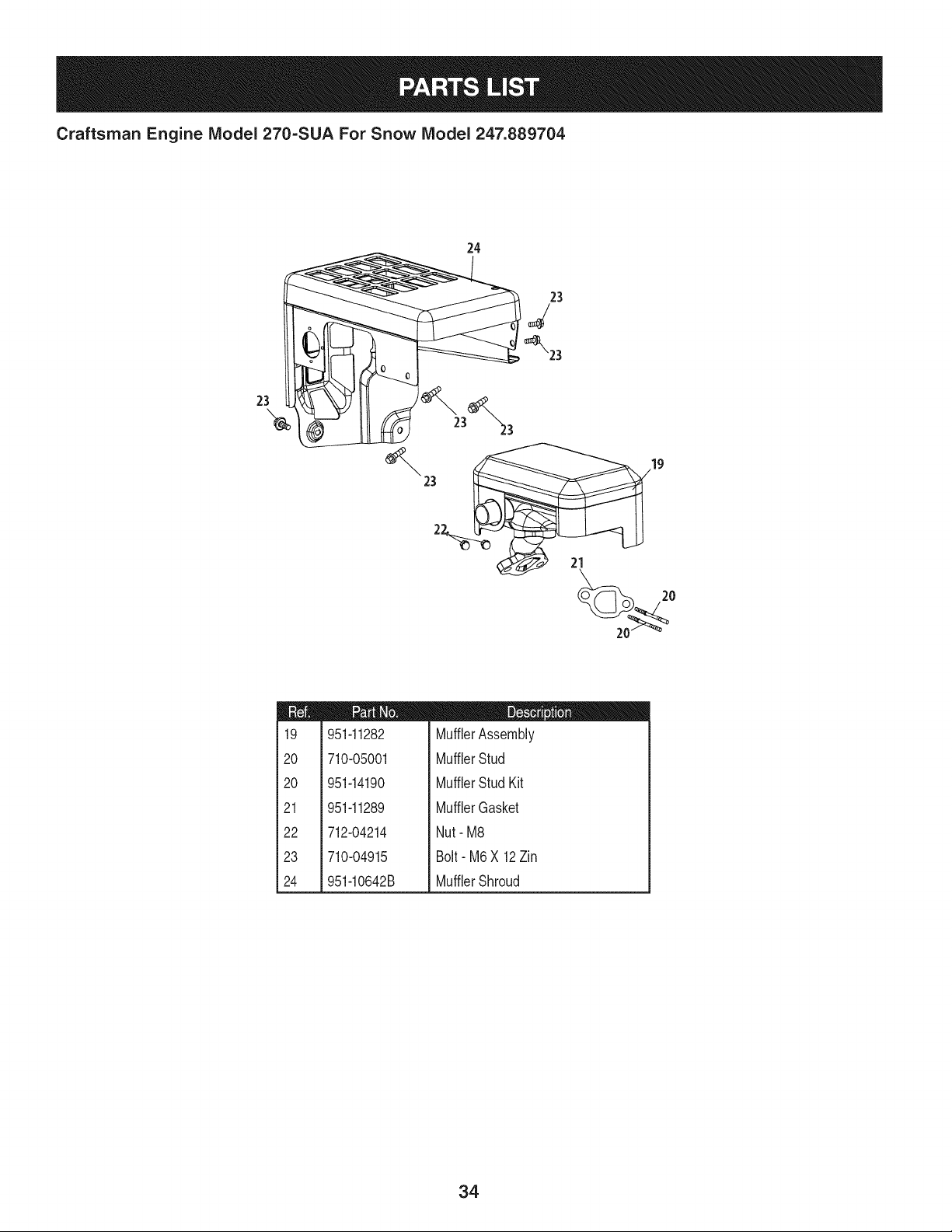
Craftsman Engine Model 270=SUA For Snow Model 247.889704
24
23
23
2
21
m
l
i
i19
!
i
120
i
i
i
i20
!
!
i
121
i
i
122
i
i
i
i23
!
i
i
124
i
951-11282
710-05001
951-14190
951-11289
712-04214
710-04915
951-10642B
m = 0 O
MufflerAssembly
MufflerStud
MufflerStud Kit
MufflerGasket
Nut- M8
Bolt- M6X 12Zin
MufflerShroud
34
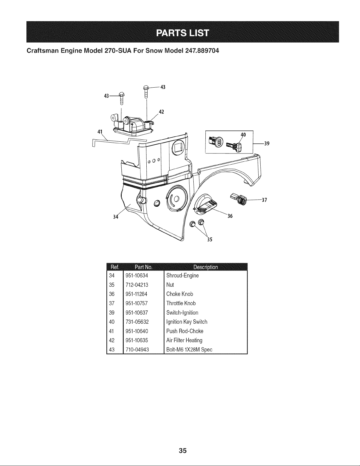
Craftsman Engine Model 270=SUA For Snow Model 247.889704
41 _42
°0
37
35
m
34
35
36
37
39
4O
41
42
43
951-10634
712-04213
951-11284
951-10757
951-10637
731-05632
951-10640
951-10635
710-04943
D = O O
Shroud-Engine
Nut
ChokeKnob
ThrottleKnob
Switch-Ignition
IgnitionKeySwitch
PushRod-Choke
Air FilterHeating
Bolt-M61X28MSpec
35
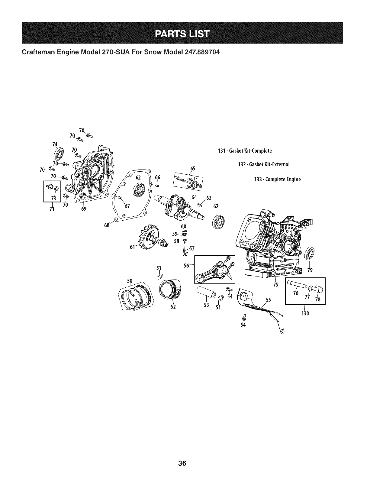
Craftsman Engine IViodel 270=SUA For Snow IViodel 247.889704
131-6asketKit-Complete
132-6asketKit-External
133- CompleteEngine
36
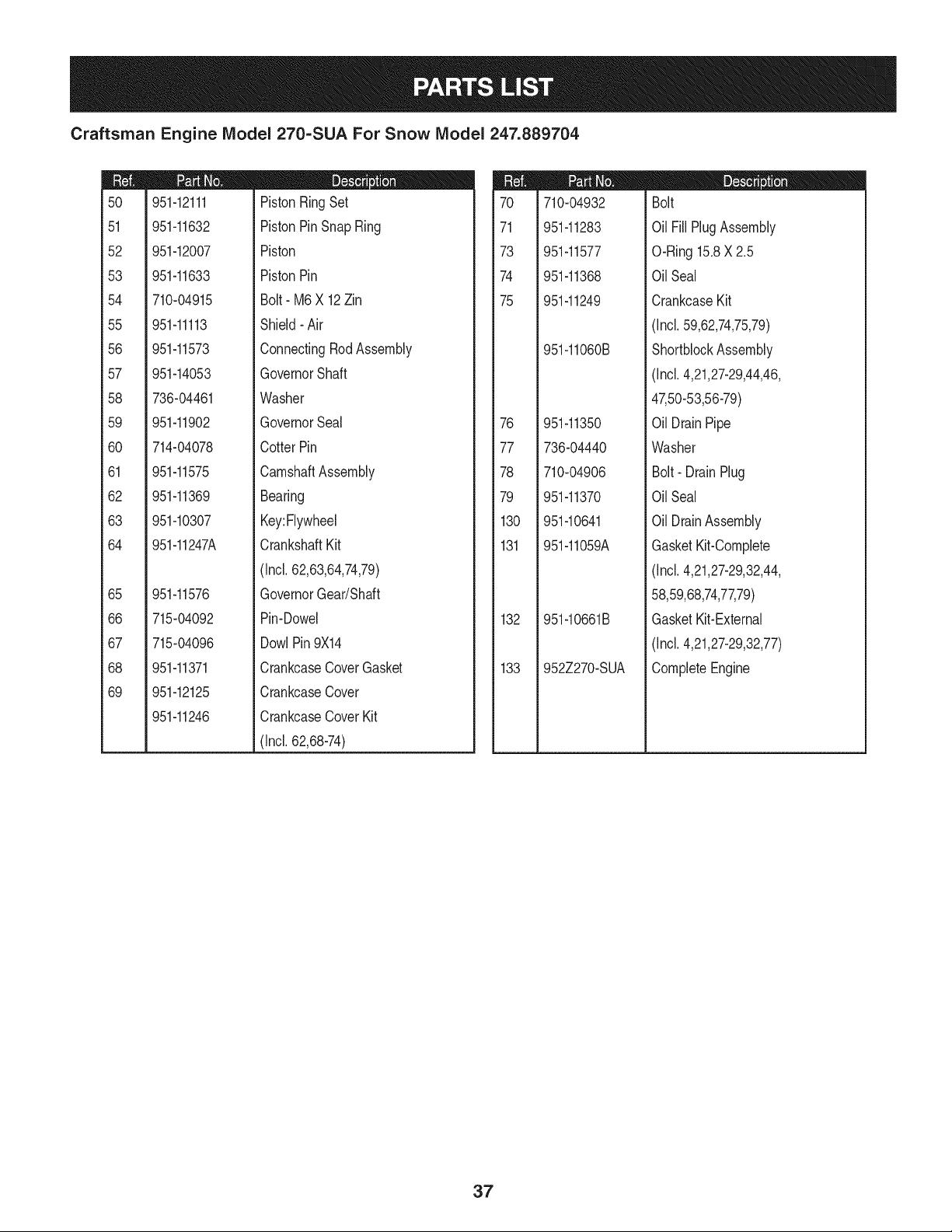
Craftsman Engine IViodel 270=SUA For Snow IViodel 247.889704
m
5O
51
52
53
54
55
56
57
58
59
6O
61
62
63
64
65
66
67
68
69
951-12111
951-11632
951-12007
951-11633
710-04915
951-11113
951-11573
951-14053
736-04461
951-11902
714-04078
951-11575
951-11369
951-10307
951-11247A
951-11576
715-04092
715-04096
951-11371
951-12125
951-11246
D = O
PistonRingSet
PistonPinSnap Ring
Piston
PistonPin
Bolt- M6X 12Zin
Shield- Air
ConnectingRodAssembly
GovernorShaft
Washer
GovernorSeal
CotterPin
CamshaftAssembly
Bearing
Key:Flywheel
CrankshaftKit
(Incl.62,63,64,74,79)
GovernorGear/Shaft
Pin-Dowel
DowlPin 9X14
CrankcaseCoverGasket
CrankcaseCover
CrankcaseCoverKit
(Incl.62,68-74)
m
7O
71
73
74
75
76
77
78
79
130
131
132
133
710-04932
951-11283
951-11577
951-11368
951-11249
951-11060B
951-11350
736-04440
710-04906
951-11370
951-10641
951-11059A
951-10661B
952Z270-SUA
D = O O
Bolt
Oil FillPlugAssembly
O-Ring15.8X 2.5
OilSeal
CrankcaseKit
(Incl.59,62,74,75,79)
ShortblockAssembly
(Incl.4,21,27-29,44,46,
47,50-53,56-79)
Oil DrainPipe
Washer
Bolt- DrainPlug
OilSeal
Oil DrainAssembly
GasketKit-Complete
(Incl.4,21,27-29,32,44,
58,59,68,74,77,79)
GasketKit-External
(Incl.4,21,27-29,32,77)
CompleteEngine
37
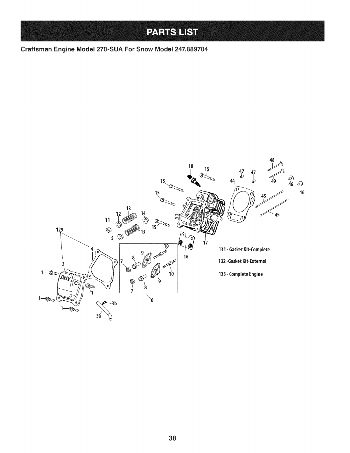
Craftsman Engine Model 270-SUAFor Snow Model 247.889704
129
15
13
18
17
44 _p 49 46 _46
_ U" -"45
131-GasketKit-Complete
132-GasketKit-External
133-CompleteEngine
38
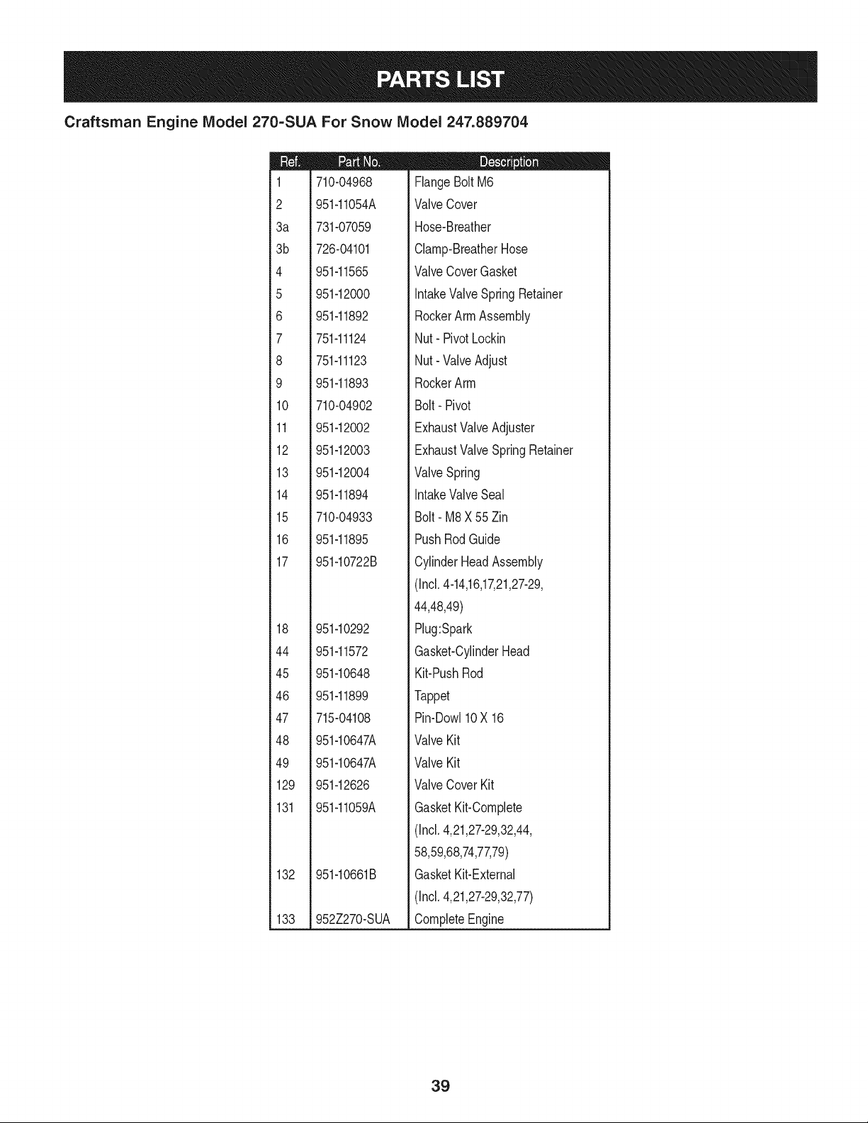
Craftsman Engine IViodel 270=SUA For Snow IViodel 247.889704
m
1
2
3a
3b
4
5
6
7
8
9
10
11
12
13
14
15
16
17
18
44
45
46
47
48
49
129
131
132
133
710-04968
951-11054A
731-07059
726-04101
951-11565
951-12000
951-11892
751-11124
751-11123
951-11893
710-04902
951-12002
951-12003
951-12004
951-11894
710-04933
951-11895
951-10722B
951-10292
951-11572
951-10648
951-11899
715-04108
951-10647A
951-10647A
951-12626
951-11059A
951-10661B
952Z270-SUA
D = O O
FlangeBoltM6
ValveCover
Hose-Breather
Clamp-BreatherHose
ValveCoverGasket
IntakeValveSpring Retainer
RockerArmAssembly
Nut- PivotLockin
Nut- ValveAdjust
RockerArm
Bolt- Pivot
ExhaustValveAdjuster
ExhaustValveSpringRetainer
ValveSpring
IntakeValveSeal
Bolt- M8X 55Zin
PushRodGuide
CylinderHeadAssembly
(Incl.4-14,16,17,21,27-29,
44,48,49)
Plug:Spark
Gasket-CylinderHead
Kit-PushRod
Tappet
Pin-Dow110X 16
ValveKit
ValveKit
ValveCover Kit
GasketKit-Complete
(Incl.4,21,27-29,32,44,
58,59,68,74,77,79)
GasketKit-External
(Incl.4,21,27-29,32,77)
CompleteEngine
39

Craftsman Engine IViodel 270=SUA For Snow IViodel 247.889704
27
134-CarburetorKit- Deni
135- CarburetorKit- Huayi
w
4O
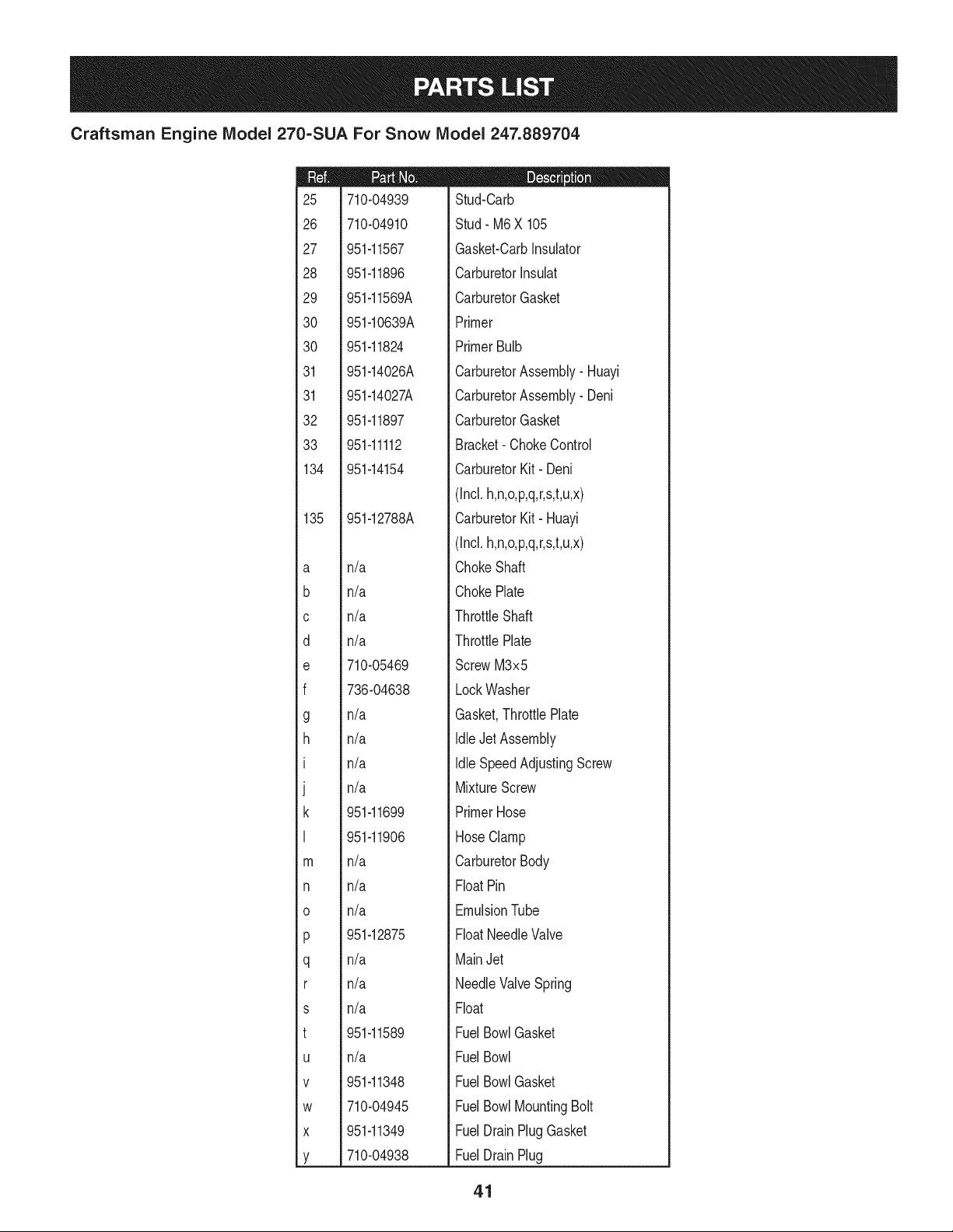
Craftsman Engine IViodel 270=SUA For Snow IViodel 247.889704
m
25
26
27
28
29
30
30
31
31
32
33
134
135
a
b
C
d
e
f
g
h
I
J
k
I
I1q
n
o
P
q
r
s
t
U
V
W
X
Y
710-04939
710-04910
951-11567
951-11896
951-11569A
951-10639A
951-11824
951-14026A
951-14027A
951-11897
951-11112
951-14154
951-12788A
n/a
n/a
n/a
n/a
710-05469
736-04638
n/a
n/a
n/a
n/a
951-11699
951-11906
n/a
n/a
n/a
951-12875
n/a
n/a
n/a
951-11589
n/a
951-11348
710-04945
951-11349
710-04938
D = W O
Stud-Carb
Stud- M6X 105
Gasket-CarbInsulator
CarburetorInsuiat
CarburetorGasket
Primer
PrimerBulb
CarburetorAssembly- Huayi
CarburetorAssembly- Deni
CarburetorGasket
Bracket- ChokeControl
CarburetorKit- Deni
(Incl.h,n,o,p,q,r,s,t,u,x)
CarburetorKit- Huayi
(Incl.h,n,o,p,q,r,s,t,u,x)
ChokeShaft
ChokePlate
ThrottleShaft
ThrottlePlate
ScrewM3x5
LockWasher
Gasket,ThrottlePlate
IdleJet Assembly
Idle SpeedAdjustingScrew
MixtureScrew
PrimerHose
HoseClamp
CarburetorBody
FloatPin
EmulsionTube
FloatNeedleValve
MainJet
NeedleValveSpring
Float
FuelBowlGasket
FuelBowl
FuelBowlGasket
FuelBowlMountingBolt
FuelDrainPlugGasket
FuelDrainPlug
41
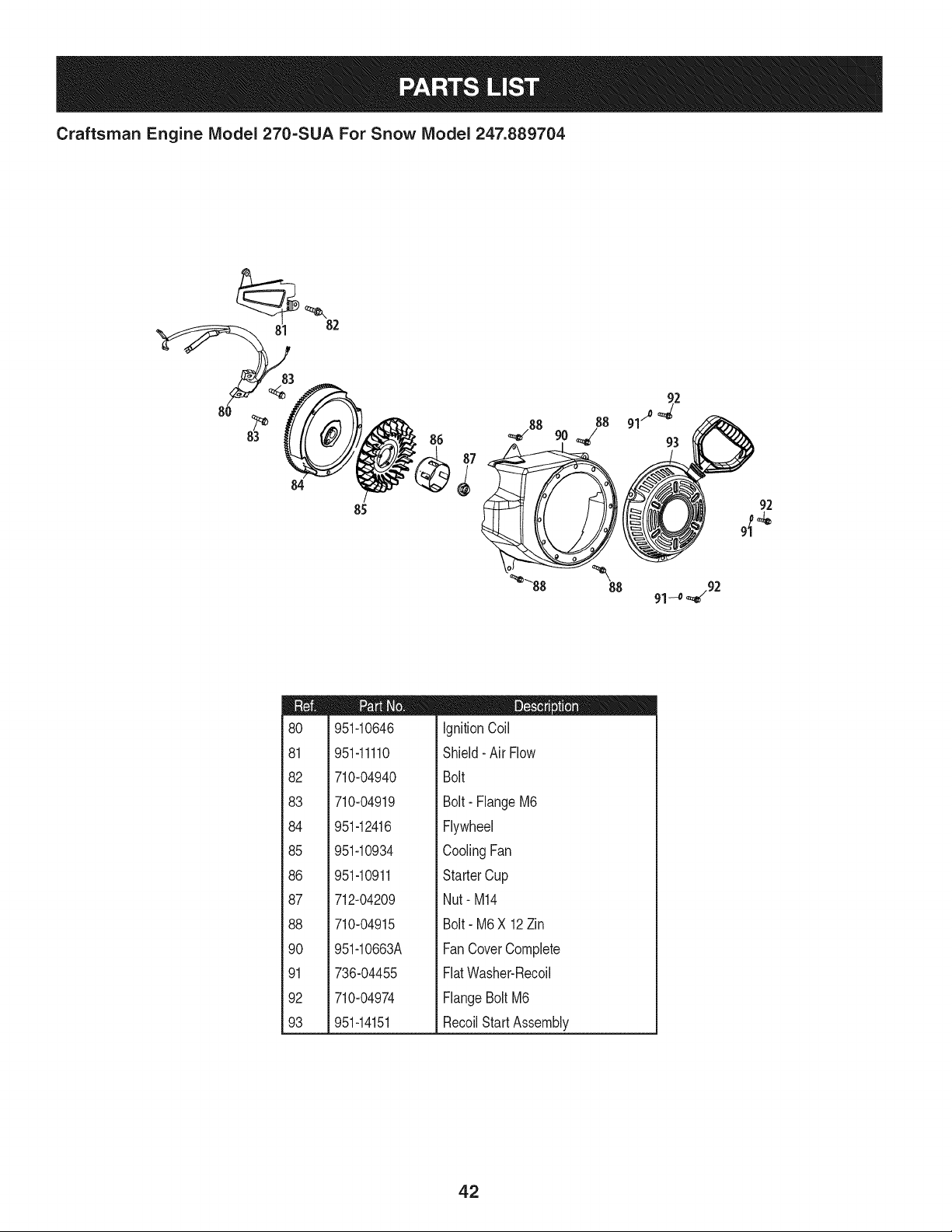
Craftsman Engine IViodel 270-SUA For Snow IViodel 247.889704
82
84
85
m
8O
81
82
83
84
85
86
87
88
90
91
92
93
951-10646
951-11110
710-04940
710-04919
951-12416
951-10934
951-10911
712-04209
710-04915
951-10663A
736-04455
710-04974
951-14151
D = O O
IgnitionCoil
Shield- Air Flow
Bolt
Bolt- FlangeM6
Flywheel
CoolingFan
StarterCup
Nut- M14
Bolt- M6X 12Zin
FanCoverComplete
FlatWasher-Recoil
FlangeBolt M6
RecoilStartAssembly
42
Craftsman Engine IViodel 270=SUA For Snow IViodel 247.889704
,114
115
95 102 _---115
9s- 97 9s
105
94
105
104
m
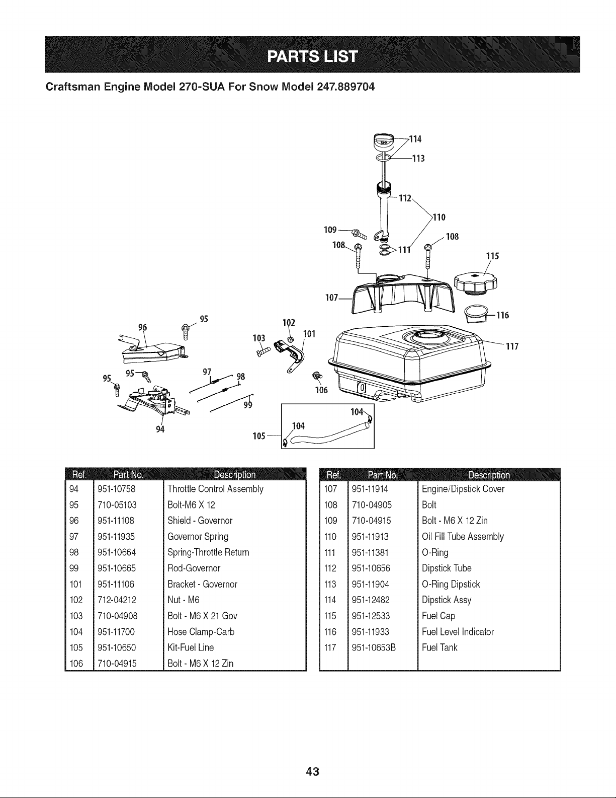
94
95
96
97
98
99
101
102
103
104
105
106
951-10758
710-05103
951-11108
951-11935
951-10664
951-10665
951-11106
712-04212
710-04908
951-11700
951-10650
710-04915
D = O 0
ThrottleControlAssembly
Bolt-M6X 12
Shield- Governor
GovernorSpring
Spring-ThrottleReturn
Rod-Governor
Bracket-Governor
Nut- M6
Bolt- M6X 21 Gov
HoseClamp-Oarb
Kit-FuelLine
Bolt- M6X 12Zin
m
107
108
109
110
111
112
113
114
115
116
117
951-11914
710-04905
710-04915
951-11913
951-11381
951-10656
951-11904
951-12482
951-12533
951-11933
951-10653B
D = O 0
Engine/DipstickCover
Bolt
Bolt- M6X 12Zin
Oil FillTubeAssembly
O-Ring
DipstickTube
O-RingDipstick
DipstickAssy
FuelCap
FuelLevelIndicator
FuelTank
43
Craftsman Engine IViodel 270=SUA For Snow IViodel 247.889704
23
m
i
1118
1
1
1
i119
!
i
i 120
1
1
1
1121
1
1
1
i 122
!
i
i 123
1
1
1
i 124
!
!
i
i 125
1
1
i 126
1
1
1
i 127
!
i
1
i 128
1
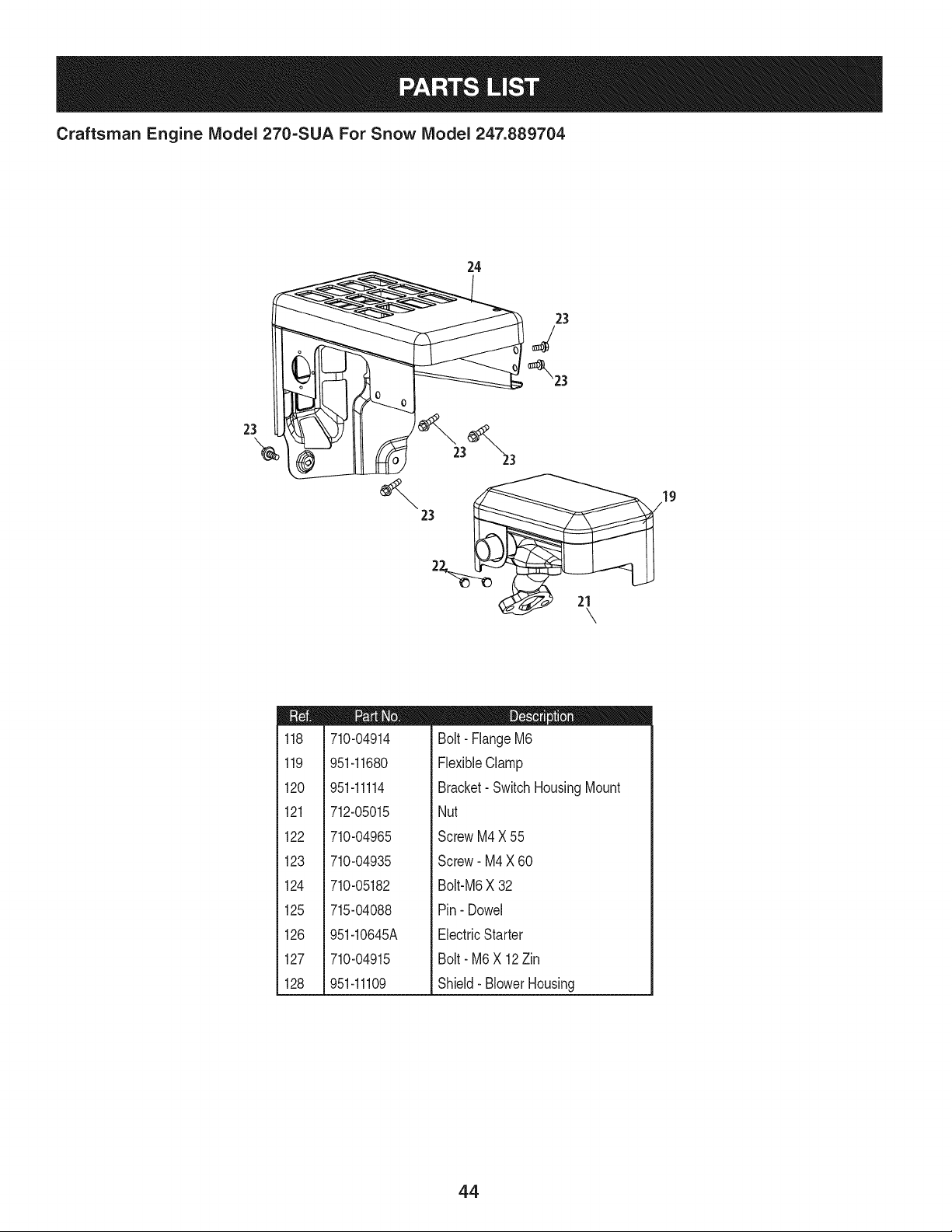
710-04914
951-11680
951-11114
712-05015
710-04965
710-04935
710-05182
715-04088
951-10645A
710-04915
951-11109
D = O !
Bolt- FlangeM6
FlexibleClamp
Bracket- SwitchHousingMount
Nut
ScrewM4X 55
Screw- M4X 60
Bolt-M6X 32
Pin- Dowel
ElectricStarter
Bolt- M6 X 12Zin
Shield- BlowerHousing
44
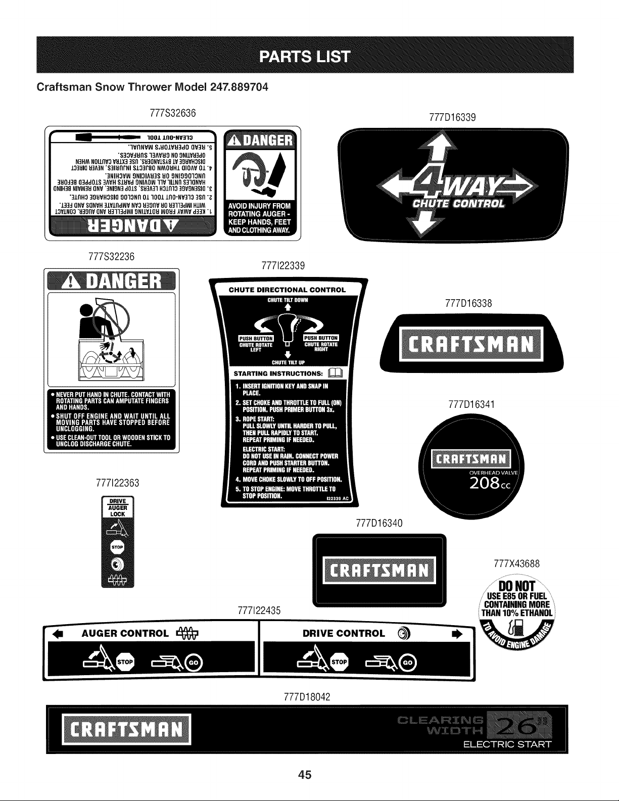
Craftsman Snow Thrower Model 247.889704
777S32636
_m _ lool zflO-NV:Zlo
"=IVflNVW S,EIO/VEI3dO QV:IEI "_
"S33V-IEInS 13AVEI9 NO9NIIVEI3dO
N3HM NOIlnV3 VSIX_ 3sn "SU3ON¥1S_8lV 39UVHOSIG
IO]UIO U3A]N 'S31UflrNI $103r80 NMOUHI QIOAV 01 "1
"3NIHOV_ 9NIOIAU3S UO 9NI9901ONfl
]H0_38 Q3ddOiS 3AVH SIHVd 9NIAOW 11V lllNfl S31QNVH
gNIH39 NIV_3_ ONV'3NION3 dOiS 'SU3A31HOlfl13 30VON3SIQ"I
']lflH3 ]9UVHOSIO 9010Nfl 01 ]OO1 lflO-NY313 _Sfl ";
"133_ ONVSQNVH ]lVlfld_V NVOU3OflV UO U3]]3dWI HIIM
lOVlNO3 "U]gflV QNVU3113dWI 9NIIVIOU _OUJ AVMV d33X"
777D16339
777S32236
777122339
777122363
STARTING INSTRUCTIONS:
777D16338
777D16341
777D16340
AUGER CONTROL
777122435
DRIVE CONTROL _)
777X43688
USEE85 ORFUEL
CONTAININGMORE
THAN10%ETHANOL
!
777D18042
45
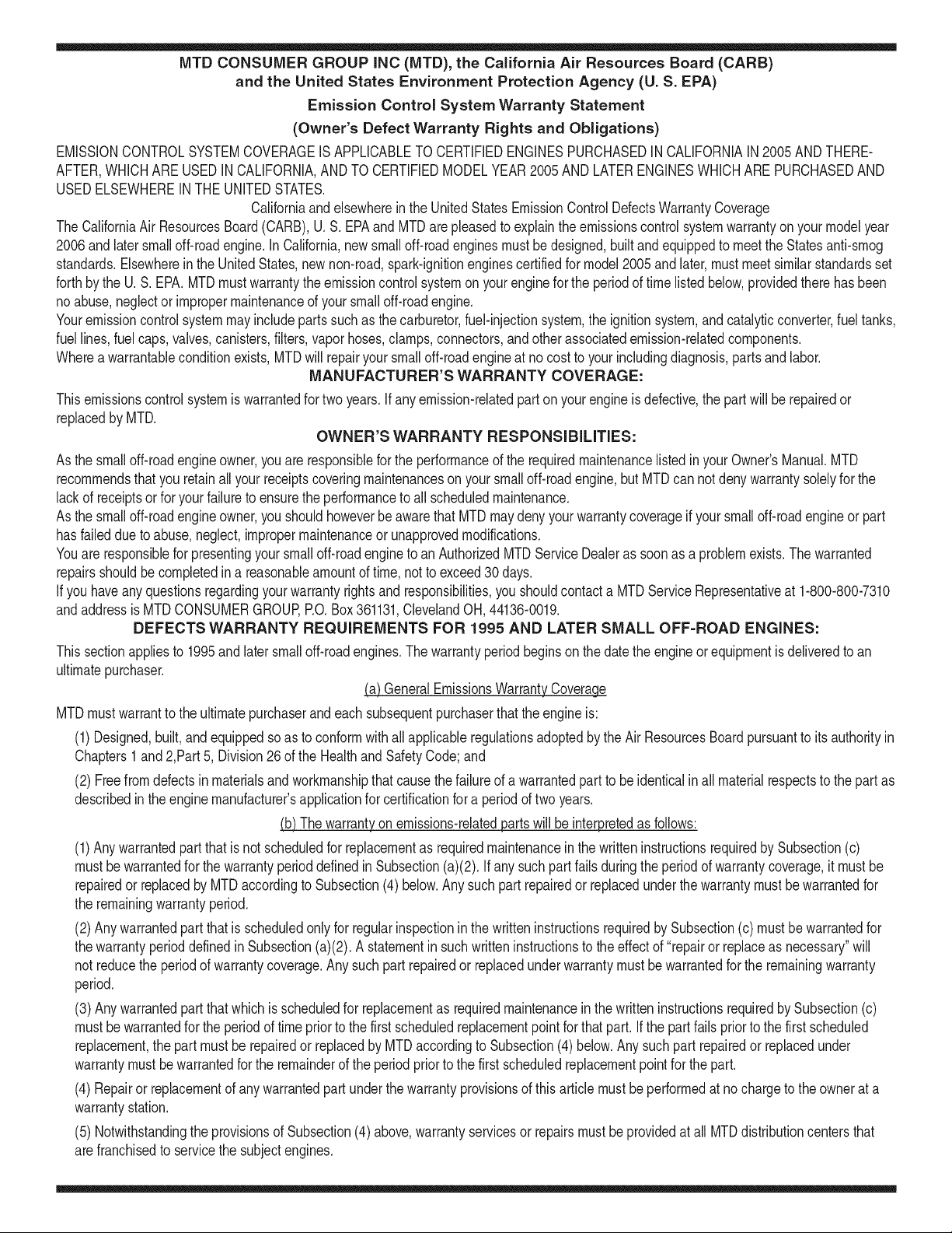
MTD CONSUMER GROUP INC (MTD), the California Air Resources Board (CARB)
and the United States Environment Protection Agency (U. S. EPA)
Emission Control System Warranty Statement
(Owner's Defect Warranty Rights and Obligations)
EMISSIONCONTROLSYSTEMCOVERAGEIS APPLICABLETOCERTIFIEDENGINESPURCHASEDIN CALIFORNIAIN2005 ANDTHERE-
AFTER,WHICHARE USEDIN CALIFORNIA,ANDTO CERTIFIEDMODELYEAR2005 ANDLATERENGINESWHICHARE PURCHASEDAND
USEDELSEWHEREIN THEUNITEDSTATES.
Californiaandelsewherein the UnitedStatesEmissionControlDefectsWarrantyCoverage
The CaliforniaAir ResourcesBoard(CARB),U.S. EPAand MTDarepleasedto explaintheemissionscontrolsystemwarrantyon your modelyear
2006and latersmalloff-roadengine.In California,new smalloff-roadenginesmustbe designed,builtand equippedto meet theStatesanti-smog
standards.Elsewhereinthe UnitedStates,newnon-road,spark-ignitionenginescertifiedfor model2005and later,mustmeet similarstandardsset
forthby the U. S. EPA.MTDmustwarrantythe emissioncontrolsystemon yourenginefor the periodof timelisted below,providedtherehasbeen
noabuse,neglector impropermaintenanceof your smalloff-roadengine.
Youremissioncontrolsystemmayincludepartssuch as the carburetor,fuel-injectionsystem,the ignitionsystem,and catalyticconverter,fueltanks,
fuel lines,fuel caps,valves,canisters,filters,vaporhoses,clamps,connectors,andotherassociatedemission-relatedcomponents.
Wherea warrantableconditionexists,MTDwill repairyoursmall off-roadengineat nocost to yourincludingdiagnosis,partsand labor.
MANUFACTURER'S WARRANTY COVERAGE:
Thisemissionscontrolsystemis warrantedfor twoyears.If anyemission-relatedpart on yourengineis defective,the part will berepairedor
replacedby MTD.
OWNER'S WARRANTY RESPONSIBILITIES:
As the smalloff-roadengineowner,youare responsibleforthe performanceof the requiredmaintenancelistedin your Owner'sManual.MTD
recommendsthatyou retainall yourreceiptscoveringmaintenanceson yoursmalloff-roadengine,but MTDcan not denywarrantysolelyfor the
lackof receiptsor foryour failureto ensurethe performanceto all scheduledmaintenance.
As the smalloff-roadengineowner,youshouldhoweverbe awarethat MTDmaydenyyour warrantycoverageif yoursmalloff-roadengine orpart
hasfaileddue toabuse,neglect,impropermaintenanceor unapprovedmodifications.
Youare responsiblefor presentingyour smalloff-roadengineto an AuthorizedMTDServiceDealeras soonas a problemexists.Thewarranted
repairsshouldbe completedina reasonableamountof time,notto exceed30 days.
Ifyou haveanyquestionsregardingyourwarrantyrightsand responsibilities,you shouldcontacta MTDServiceRepresentativeat 1-800-800-7310
andaddressis MTDCONSUMERGROUP,RO. Box361131,ClevelandOH,44136-0019.
DEFECTS WARRANTY REQUIREMENTS FOR 1995 AND LATER SMALL OFF-ROAD ENGINES:
Thissectionappliesto 1995and later smalloff-roadengines.The warrantyperiodbeginson the datethe engineor equipmentis deliveredto an
ultimatepurchaser.
(a) GeneralEmissionsWarrantyCoverage_
MTDmustwarrantto the ultimatepurchaserand eachsubsequentpurchaserthat the engineis:
(1)Designed,built,andequippedsoas to conformwithallapplicableregulationsadoptedby the Air ResourcesBoardpursuantto itsauthorityin
Chapters1 and2,Part 5, Division26 of the HealthandSafetyCode;and
(2) Freefrom defectsin materialsand workmanshipthatcausethe failureof a warrantedpart to be identicalin all materialrespectsto the partas
describedin theenginemanufacturer'sapplicationfor certificationfora periodof twoyears.
.(b)The warrantyonemissions-relatedpartswill be interpretedas follows:
(1)Anywarrantedpart that is not scheduledfor replacementas requiredmaintenanceinthe writteninstructionsrequiredby Subsection(c)
mustbewarrantedfor the warrantyperioddefinedinSubsection(a)(2). Ifany suchpartfailsduringthe periodof warrantycoverage,it mustbe
repairedor replacedby MTDaccordingto Subsection(4)below.Anysuchpart repairedor replacedunderthewarrantymustbe warrantedfor
the remainingwarrantyperiod.
(2)Any warrantedpartthat is scheduledonlyfor regularinspectioninthe writteninstructionsrequiredby Subsection(c) must bewarrantedfor
thewarrantyperioddefinedin Subsection(a)(2).A statementinsuchwritteninstructionsto the effectof "repairor replaceas necessary"will
not reducethe periodof warrantycoverage.Anysuchpart repairedor replacedunderwarrantymustbe warrantedforthe remainingwarranty
period.
(3) Anywarrantedpartthat whichis scheduledfor replacementas requiredmaintenancein the writteninstructionsrequiredby Subsection(c)
mustbewarrantedfor the periodof time priorto the first scheduledreplacementpointforthat part.Ifthe part fails priorto thefirst scheduled
replacement,the part mustbe repairedor replacedby MTDaccordingto Subsection(4) below.Any suchpart repairedor replacedunder
warrantymustbe warrantedfor the remainderof the period priorto the first scheduledreplacementpointfor the part.
(4) Repairor replacementof any warrantedpartunderthewarrantyprovisionsof thisarticle mustbe performedat no chargeto the ownerat a
warrantystation.
(5) Notwithstandingthe provisionsof Subsection(4)above,warrantyservicesor repairsmustbe providedat all MTDdistributioncentersthat
arefranchisedto servicethe subjectengines.
(6)Theownermustnotbechargedfordiagnosticlaborthatleadstothedeterminationthatawarrantedpartisinfactdefective,providedthat
suchdiagnosticworkisperformedatawarrantystation.
(7)Theenginemanufacturerisliablefordamagestootherenginecomponentsproximatelycausedbyafailureunderwarrantyofanywarranted
part.
(8)Throughouttheengine'swarrantyperioddefinedinSubsection(a)(2),MTDwillmaintainasupplyofwarrantedpartssufficienttomeetthe
expecteddemandforsuchparts.
(9)Anyreplacementpartmaybeusedintheperformanceofanywarrantymaintenanceorrepairsandmustbeprovidedwithoutchargetothe
owner.SuchusewillnotreducethewarrantyobligationsofMTD.
(10)Add-onormodifiedpartsthatarenotexemptedbytheAirResourcesBoardmaynotbeused.Theuseofanynon-exemptedadd-onor
modifiedpartsshallbegroundsfordisallowingawarrantyclaimmadeinaccordancewiththisarticle.Theenginemanufacturershallnotbe
liableunderthisarticletowarrantfailuresofwarrantedpartscausedbytheuseofnon-exemptedadd-onormodifiedpart.
(c) MTDwill includea copy of the followingemissionwarrantypartslist witheach newengine,usingthoseportionsof the list applicableto the
e__&gine.
(1)FuelMeteringSystem
• Coldstart enrichmentsystem(soft choke)
,,Carburetorandinternalparts
• Fuel Pump
• FuelTank
(2)Air InductionSystem
• Aircleaner
• Intakemanifold
(3) IgnitionSystem
• Sparkplug(s)
• MagnetoIgnitionSystem
(4)ExhaustSystem
Catalyticconverter
• SAI (Reedvalve)
(5) MiscellaneousItemsUsedin AboveSystem
Vacuum,temperature, position,time sensitivevalvesand switches
Connectorsandassemblies
(6) Evaporativecontrol
• Fuel Hosecertifiedfor ARBevaporativeemissionof 2006.
• Fuel HoseClamps
Tetheredfuel cap
Carboncanister
• Vaporlines
GD0C-100174Rev.B
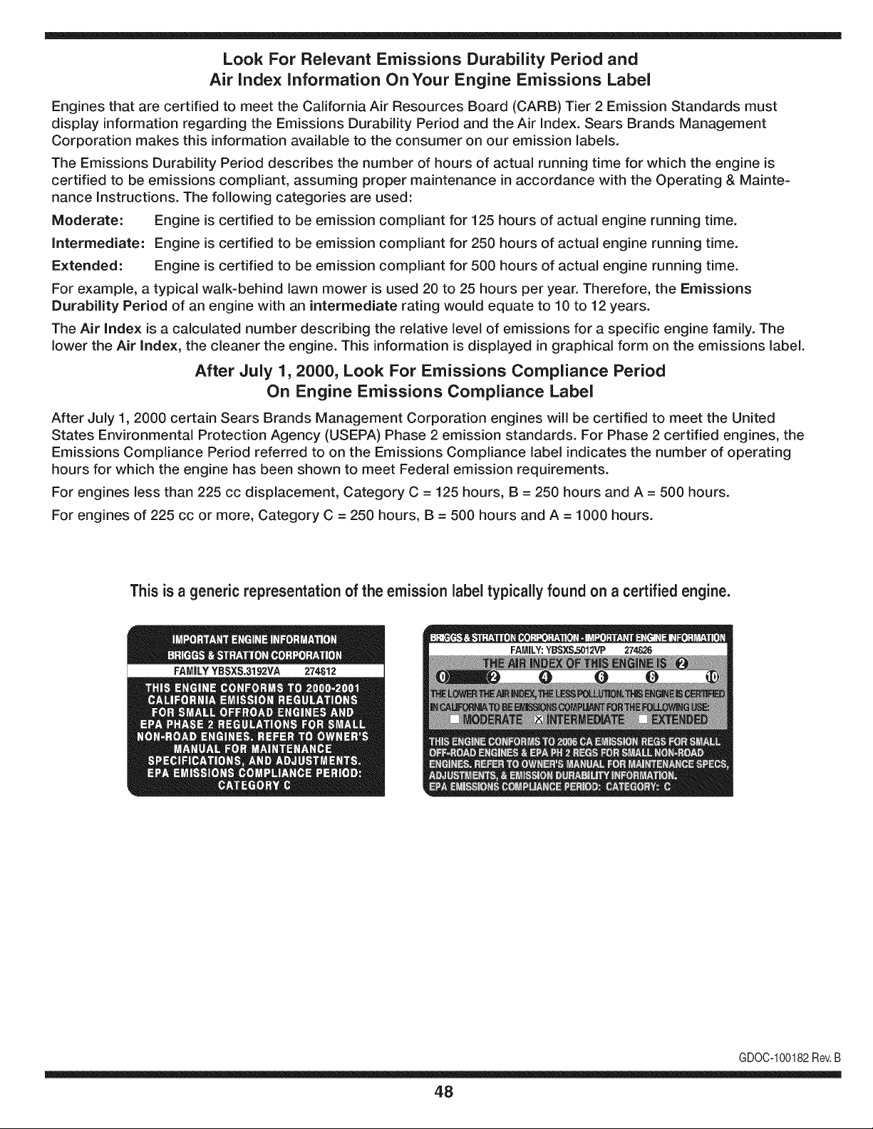
Look For Relevant Emissions Durability Period and
Air index information On Your Engine Emissions Label
Engines that are certified to meet the California Air Resources Board (CARB) Tier 2 Emission Standards must
display information regarding the Emissions Durability Period and the Air Index. Sears Brands Management
Corporation makes this information available to the consumer on our emission labels.
The Emissions Durability Period describes the number of hours of actual running time for which the engine is
certified to be emissions compliant, assuming proper maintenance in accordance with the Operating & Mainte-
nance Instructions. The following categories are used:
Moderate: Engine is certified to be emission compliant for 125 hours of actual engine running time.
Intermediate: Engine is certified to be emission compliant for 250 hours of actual engine running time.
Extended: Engine is certified to be emission compliant for 500 hours of actual engine running time.
For example, a typical walk-behind lawn mower is used 20 to 25 hours per year. Therefore, the Emissions
Durability Period of an engine with an intermediate rating would equate to 10 to 12 years.
The Air index is a calculated number describing the relative level of emissions for a specific engine family. The
lower the Air Index, the cleaner the engine. This information is displayed in graphical form on the emissions label.
After July 1,2000, Look For Emissions Compliance Period
On Engine Emissions Compliance Label
After July 1, 2000 certain Sears Brands Management Corporation engines will be certified to meet the United
States Environmental Protection Agency (USEPA) Phase 2 emission standards. For Phase 2 certified engines, the
Emissions Compliance Period referred to on the Emissions Compliance label indicates the number of operating
hours for which the engine has been shown to meet Federal emission requirements.
For engines less than 225 cc displacement, Category C = 125 hours, B = 250 hours and A = 500 hours.
For engines of 225 cc or more, Category C = 250 hours, B = 500 hours and A = 1000 hours.
This is a generic representation of the emission label typically found on a certified engine.
FAMILYYBSXS.3192VA 274812
GDOC-100182Rev.B
48
Congratulations on making a smart purchase. Your new Craftsman® product is designed and
manufactured for years of dependable operation. But like all products, it may require repair
from time to time. That's when having a Repair Protection Agreement can save you money and
aggravation.
Here's what the Repair Protection Agreement* includes:
[] Expert service by our 10,000 professional repair specialists
[] Unlimited service and no charge for parts and labor on all covered repairs
[] Product replacement up to $1500 if your covered product can't be fixed
[] Discount of 25% from regular price of service and related installed parts not covered by the
agreement; also, 25% off regular price of preventive maintenance check
[] Fast help by phone - we call it Rapid Resolution - phone support from a Sears representative.
Think of us as a "talking owner's manual."
Once you purchase the Repair Protection Agreement, a simple phone call is all that it takes for you
to schedule service. You can call anytime day or night, or schedule a service appointment online.
The Repair Protection Agreement is a risk-free purchase. If you cancel for any reason during the
product warranty period, we will provide a full refund. Or, a prorated refund anytime after the
product warranty period expires. Purchase your Repair Protection Agreement today!
Some limitations and exclusions apply. For prices and additional information in the U.S.A.
call 1=800=827=6655.
*Coverage in Canada varies on some items. For full details call Sears Canada at 1=800=361=
6665.
Sears Installation Service
For Sears professional installation of home appliances, garage door openers, water heaters, and
other major home items, in the U.S.A. or Canada call 1=800=4=MY=HOME®.
49
Declaraci6n de garantia ............................ Pagina 50
Practicas operaci6n seguras ..................... Pagina 51
Montaje ...................................................... Pagina 55
Operaci6n .................................................. Pagina 61
Servicio y Mantenimiento .......................... Pagina 65
Almacenamiento fuera de temporada ....... Pagina 73
Soluci6n de problemas .............................. Pagina 74
Acuerdo de protecci6n para reparaciones .... Pagina 79
Lista de piezas ........................................... Pagina 28
NOmero de servicio ................................... Cubierta
posterior
GARANTJA COMPLETA CRAFTSMAN POR DOS ANOS
PORDOSANOSapartir de la fechade lacornpra,este productoest_garantizadopor defectosen los rnaterialesy la rnanode obra.
Los productosdefectuososser&nreparadossin costoo reemplazadossin costosi la reparaci6nnoest&disponible.
GARANTJA DE POR VlDA LIMITADA ADIClONAL en la tolva de UPPER y LOWER
PARASIEMPREY CUANDOSE UTILIZApor el propietariooriginaldespu6sdel segundoaSodesdela fechade compra,el conductosuperiore
inferiorde estequitanievesest_ngarantizadoscontracualquierdefectode rnaterialeso rnanode obra debeserverificadoporun proveedorde
servicioautorizadoSears.Con el cornprobantede cornpra,usted recibir_una rarnpanuevade forrnagratuita.Ustedes responsablepor el costo
de larnanode obrade instalaci6ny otrosgastosocasionadosparaverificarel defecto.
Paraobtener inforrnaci6nsobreel alcancede la garantiay solicitarla reparaci6no el reernplazo,visiteel sitioWeb:www.craftsrnan.corn
Esta garantiacubre0NICAMENTElos defectos en los materiales y en la rnanode obra. EstagarantiaNOcubre:
• Elernentosno renovablesquepuedendesgastarsepor el uso normal,duranteel plazodela garantia,incluyendoentreotros,las barrenas,
las paletasdelas barrenas,los cortadoresde desplazarniento,laszapatasantideslizantes,la placade raspado,lospasadoresde cuchilla,
la bujia,elfiltro de aire,las correasy el filtrode aceite.
• Serviciosde rnantenirnientoest_.ndar,carnbiosde aceiteo afinaci6n.
• Carnbiode neurn_.ticoso reparacionespor pinchadurascon objetosexternoscornoclavos,espinas,toconeso vidrios.
• Reernplazoo reparaci6nde neurn_.ticoso ruedascornoresultadodel desgastenormal,unaccident&o funcionarniento
o rnantenirnientoincorrectos.
• Reparacionesrequeridascornoresultadodel uso inadecuadopot partedeloperador,incluyendoentreotrosel da_oocasionadopor objetos
queirnpactanla rn_.quinay quetuercenel bastidor,el ejede labarrena,etc.,o debidoa que el motorrueaceleradoen exceso.
• Reparacionesnecesariasdebidoa negligenciadel operador,incluyendoentre otros,da_osrnec_.nicoy el6ctricoocasionadopor
unalrnacenarnientono apropiado,fallapor el uso deaceitede gradoy/o cantidadnoapropiadoso falla porno dar rnantenirniento
alequipo deacuerdocon las instruccionescontenidasenel manualdel operador.
• Lirnpiezao reparacionesdel motor(sisternade combustible)debidasa combustiblequese deterrninaest,.contarninadou oxidado(viejo).
Engeneral,el combustibledebeutilizarseen unperiodono mayorde 30 dias a partirde su adquisici6n.
• Eldeterioroy desgastenormalde losacabadosexteriores,o reernplazode laetiquetadelproducto.
Lapresentegaranfiase anulasi se utilizaeste productoalgunavez paraprestarservicioscornercialeso si se Ioalquilaa otra persona.
Estagaranfialeotorgaderechoslegalesespecificos,peroustedpodriagozarde otrosderechosen raz6nde su lugarde residencia.
Sears Brands Management Corporation, Hoffman Estates, IL 60179
Tipode aceitedelmotor:
Capacidaddeaceitedel motor:
Capacidaddecombustible:
Bujfas:
Separaci6nde lasbujias:
5W-30
20onzas
2 cuartos
F6RTC(951-10292)
.020"a .030"
N_merode modelo ..........................................................
N_merode serie ..............................................................
Fechade compra .............................................................
Registrearriba elnOrnerodel rnodelo,elnOrnerode seriey la fecha
decornpra
© Sears Brands,LLC
50
Lapresenciade este sfrnboloindicaque setrata de instrucciones
irnportantesde seguridadquese debenrespetarpara evitar
poneren peligrosu seguridadpersonaly/o materialy la de otras
personas.Lea y siga todaslas instruccionesde estemanualantes
de poneren funcionarnientoesta rn_.quina.Si no respetaestas
instruccionespodrfaprovocarlesionespersonales.Cuandoveaeste
sfrnbolo,i presteatenci6na la advertencia!
PROPOSICION 65 DE CALIFORNIA
Elescapedel motorde esteproducto,algunosde suscornponentes
y algunoscornponentesdelvehfculocontieneno liberan sustancias
qufrnicasque elestado deCaliforniaconsideraque puedenproducir
c_.ncer,defectosde nacirnientouotros problernasreproductivos.
Estarn_.quinarueconstruidaparaseroperadadeacuerdocon
las reglasde seguridadcontenidaseneste manual.AI igualque
concualquiertipo de equipornotorizado,undescuidoo error por
partedeloperadorpuedeproducirlesionesgraves.Estarn_.quina
es capazde arnputarrnanosy piesy dearrojarobjetoscon gran
fuerza.Deno respetarlas instruccionesde seguridadsiguientesse
puedenproducirlesionesgraveso la rnuerte.
Su responsabilidad--Restrinja el usode estarn_.quina
rnotorizadaalas personasque lean,cornprendany respetenlas
advertenciase instruccionesque aparecenen este manualyen la
rn_.quina.
iGUARDEESTASINSTRUCCIONES!
CAPACITACI6N
• Lea,entienday curnplatodaslas instruccionesincluidasen
la rn_.quinayen los rnanualesantesdernontarlay utiNzarla.
Guardeestemanualenun lugarseguroparaconsultasfuturasy
peri6dicas,asf cornoparasolicitarrepuestos.
• Leael ManualdelOperadory sigatodas las advertenciase
instruccionesde seguridad.Elfracasode hacerasf puedecausar
la heridaseriaal operadory/o personaspresentes.
• Farniliarfcesecontodoslos controlesy con el usoadecuado
delos rnisrnos.Sepac6rnodetenerlarn_.quinay desactivarlos
controlesr_.pidarnente.
• No perrnitanuncaque los ni_osrnenoresde 14a_osutilicen
estarn_.quina.Los ni_osde 14a_osen adelantedebenleery
entenderlas instruccionesde operaci6ny norrnasdeseguridad
contenidasen este manual,yen la rn_.quinaydebenser entrena-
dosy supervisadosporun adulto.
• Nuncaperrnitaque los adultosoperenestarn_.quinasin recibir
antesla instrucci6napropiada.
• Losobjetosarrojadospor la rn_.quinapuedenproducirlesiones
graves.Planifiqueel patr6nenel queva a ir arrojandonievepara
evitarque ladescargade materialse realicehacialos carninos,
los observadores,etc.
• Mantengaa losobservadores,ayudantes,rnascotasy ni_ospor
Io rnenosa 75 piesde la rn_.quinarnientrasla rnisrnaest,.en
funcionarniento.Detengala rn_.quinasi alguienseacerca.
• Seaprecavidopara evitarpatinarseo caerseespecialrnente
cuandoopera la rn_.quinaen reversa.
PR E PA RATIVO S
Inspeccionerninuciosarnenteel _.readondeutilizar_,el equipo.Saque
todoslos felpudos,peri6dicos,trineos,tablas,cablesy otrosobjetos
extra_oscon los que podrfatropezaro quepodrfanser arrojadospor
labarrena/irnpulsor.
• Paraprotegerselosojos utilice siernpreanteojoso antiparras
de seguridadrnientrasopera la rn_.quinao rnientrasla ajusta
o repara.Losobjetosarrojadosquerebotanpuedenproducir
lesionesocularesgraves.
• Noopere larn_.quinasin la vestirnentaadecuadaparaestar al
airelibre en invierno.No utilicealhajas,bufandaslargasu otras
prendassueltasquepodrfanenredarseenlas partesrn6viles.
UtiNceun calzadoespecialparasuperficiesresbaladizas.
• Useun prolongadory un tornacorrientede trescables con
conexi6na tierraparatodaslas rn_.quinascon rnotoresde
encendidoel_ctrico.
• Ajustela alturade lacaja del tornacorrientepara Nrnpiarla grava
o las superficiescon piedrastrituradas.
• Desengranetodaslas palancasde controlantesde arrancarel
motor.
• Nuncaintenterealizarajustesrnientrasel motorest,. enrnarcha
exceptoen los casosespecfficarnenterecornendadosen el
manualdel operador.
• Dejeque elmotor y la rn_.quinase adaptena laternperatura
exteriorantesde cornenzara sacarla nieve.
51
Manejo seguro de la gasolina
Paraevitarlesionespersonales0 daSosrnaterialestengarnucho
cuidadocuandotrabajecon gasolina.Lagasolinaes surnarnente
inflarnabley sus vaporespuedencausarexplosiones.Si se derrarna
gasolinaencirna0 sobrela ropase puedelesionargravernenteya que
se puedeincendiar. L&vesela piely c&rnbiesede ropade inrnediato.
• Utilices610los recipientesparagasolinaautorizados.
• Apaguetodoslos cigarrillos,cigarros,pipasy otras fuentesde
cornbusfi6n.
• Nuncacarguecombustibleen larn&quinaen un espaciocerrado.
• Nuncasaquela tapadelcombustibleni agreguecombustible
rnientrasel motorest&caliente0 en rnarcha.
• Dejequeel motorse enfriepor I0 rnenosdos rninutosantesde
volvera cargarcombustible.
• Nuncalleneen excesoel dep6sitode combustible.Lleneel
tanquea no rn&sde1/2pulgadapordebajode la basedelcuello
de Ilenadodejandoespaciopara ladilataci6ndeIcombustible.
• Vuelvaa colocarla tapade la gasoiinay aj_stelabien.
• Lirnpieel combustiblequese hayaderrarnadosobreel motory el
equipo.Trasladela rn&quinaa otra zona. Espere5 rninutosantes
deencenderel motor.
• Nuncaalrnacenela rn&quina0 el recipientede combustibleen
unespaciocerradodondehayafuego,chispas0 luz piloto(por
ejernplo,hornos,calentadoresdeagua,calefactores,secadores
de ropa,etc.).
• Dejequela rn_.quinase enfrieporIo rnenos5 rninutosantesde
guardarla.
• NuncaIlenelos recipientesen el interiordeun vehiculoo carni6n
ocaja de rernolquecon recubrirnientospl_.sticos.Coloque
siernprelos recipientesenel pisoy lejosdelvehiculoantesde
Ilenarlos.
• Sies posible,retireel equipoa gasolinadel carni6no rernolque
y II_neloen el suelo.Siesto noes posible,Ileneel equipoen un
rernolquecon contenedorport_.til,envez dedesdeuna boquilla
dispensadoradegasolina.
• Mantengala boquilladispensadoraen contactocon el hordedel
dep6sitode combustibleo con la aberturadel recipienteen todo
rnornento,hastaterrninarla carga.No utiliceun dispositivode
apertura/cierrede boquilla.
FUNCIONANIIENTO
• No pongalas rnanoso los piescerca delas piezasrotatorias,
en lacajade la barrena/ irnpulsoro en el rnontajedelcanalde
descarga.Hacercontactocon piezasgiratoriaspuederesultaren
laarnputaci6nde rnanoso pies.
• La palancade controlde la barrena/ irnpulsores un dispositivo
de seguridad.Nuncaevitesu funcionarniento.De hacerlola
operaci6nde la rn_.quinaes riesgosay puedeocasionarlesiones.
• Las palancasdecontrol debenfuncionarbien en arnbasdirec-
cionesy regresarautorn_.ticarnentea la posici6nde desengrane
cuandose lassuelta.
• Nuncaoperela rn_.quinasi faltaun rnontajedel canalo si el
rnisrnoest,. daSado.Mantengatodos losdispositivosde seguri-
daden su lugaryen funcionarniento.
• Nuncaenciendaelmotor enespacioscerradoso en unazona
con pocaventilaci6n.Elescapedel motorcontienernon6xidode
carbono,ungas inodoroy letal.
• Noutilice la rn_.quinabajo la influenciadelalcoholo las drogas.
• El silenciadory el motorse calientany puedencausarquernadu-
ras.Nolos toque. Mantengaa los niSosalejados.
• Seasurnarnenteprecavidocuandooperela rn_.quinasobreuna
superficiecon gravao cuandola cruce.Mant_ngasealerta por si
se presentanpeligrosocultoso tr_.nsito.
• Tengacuidadocuandocarnbiede direcci6no cuandoopere
la rn_.quinaen pendientes.Nouse la rn_.quinaen pendientes
pronunciadas.
• Planifiqueel patr6nenel queva air arrojandonieveparaevitar
que ladescargade materialse produzcahacialas ventanas,
las paredes,losautorn6viles,etc.y evitarasi posiblesdaSos
rnaterialeso lesionesproducidasporlos rebotes.
• Nuncadirija ladescargahacialos niSos,los observadoreso las
rnascotasni dejeque nadiese paredelantede la rn_.quina.
• Nosobrecarguela capacidadde la rn_.quinatratandode sacarla
nievernuyr_.pidarnente.
• Nuncaopereesta rn_.quinasin buenavisibilidado ilurninaci6n.
Siernpredebeestar segurode que est,.bien afirrnadoy su-
jetandofirrnernentelas rnanijas.Carnine,nuncacorra.
• Cortela corrientea la barrena/ irnpulsorcuandotransportela
rn_.quinao cuandola rnisrnano est,.en uso.
• Nuncaoperela rn_.quinaaalta velocidadde desplazarniento
sobresuperficiesresbaladizas.Mirehaciaabajoy haciaatr_.sy
tengacuidadocuandovaya rnarchaatr_.s.
• Si la rn_.quinacornenzaraa vibrarde rnaneraanorrnal,detengael
motor,desconecteel cablede la bujiay p6ngalade rnaneraque
hagarnasacontrael motor.Inspeccionela rn_.quinarninuciosa-
rnenteparaver si est,.daSada.Reparetodos los daSosantesde
encendery operar la rn_.quina.
• Desengranetodas las palancasde controly detengaelmotor
antesde dejarla posici6nde operaci6n(detr_.sde las rnanijas).
Esperea que labarrena/ irnpulsorse detengaporcornpleto
antesde destaparelrnontajedelcanalo realizarajustese
inspecciones.
• Nuncapongalas rnanosenlas aberturasde descargao de
recolecci6n.Utilicesiernprela herrarnientadelirnpiezaquese
adjuntaparadestaparla aberturadedescarga.Nodestapeel
rnontajedel canal rnientrasel motorest,.en funcionarniento.
Antesde destaparlo,apagueel motory perrnanezcadetr_.sde las
rnanijashastaque todaslas partes rn6vilesse hayandetenido.
• Uses61ounionesy accesoriosaprobadospot el fabricante(por
ejernplo,pesaspara las ruedas,cadenaspara los neurn_.ticos,
cabinas,etc.). Paraobtenerrn_.sinforrnaci6nacercadeestos
ternas,Ilarneal 1-800-469-4663.
52
• Paraencenderel motor,jale de lacuerdalentarnentehastaque
sientaresistencia,luegojale r_.pidarnente.Elreplieguer_.pidode
la cuerdade arranque(tensi6nde retroceso)lejalar_,la rnanoy
el brazohaciael motor rn_.sr_.pidode Io queusted puedesoltar.
El resultadopuedenserhuesosrotos,fracturas,hernatornaso
esguinces.
• Si se presentansituacionesqueno est_.nprevistasen este
manual,seacuidadosoy use el sentidocornOn.
• Parapedirrepuestoso serviciohorarioparaeste producto,Ilarne
a 1-800-469-4663.
MANTENIMIENTO Y ALMACENAMIENTO
• Nuncaalterelos dispositivosde seguridad.Controleperi6dica-
rnenteque funcionencorrectarnente.Rernitasealas secciones
demantenirnientoy ajustede estemanual.
• Antesde realizarla lirnpieza,repararo revisarla rn_.quina,
desengranetodas laspalancasdecontroly detengael motor.
Esperea que la barrena/ irnpulsorse detengaporcornpleto.
Desconecteel cablede la bujfay p6ngalohaciendornasacontra
el motorparaevitarque se enciendaaccidentalrnente.
• Controlefrecuenternentequetodos lospernosy tornillosest_n
bienajustadosparacornprobarque la rn_.quinase encuentra
encondicionessegurasde funcionarniento.Adern_.s,hagauna
inspecci6nvisual de larn_.quinaparaverificarsi est,.da_ada.
• No carnbiela configuraci6ndel reguladordel motorni acelere
dernasiadoel rnisrno.Elreguladordel motorcontrolala velocidad
rn_.xirnaseguradefuncionarnientodelmotor.
• Las placasde raspadoy las zapatasantideslizantesque se
usancon la rn_.quinaquitanievese desgastany se da_an.
Paraprotegersu seguridad,verifiquefrecuenternentetodos los
cornponentesy reernpl_.celoss61ocon partesde los fabricantes
deequiposoriginales(OEM).iEI usode piezasque nocurnplen
con lasespecificacionesdelequipooriginalpuede resultaren
rendirnientoinadecuadoadern_.sde poneren riesgola seguridad!
• Reviselas palancasde controlperi6dicarnentepara verificar
queengraneny desengranenadecuadarnentey ajOstelossi es
necesario.Consultela secci6nde ajustesdeeste manualdel
operadorparaobtenerinstrucciones.
• Mantengao reernplacelasetiquetasde seguridade instrucciones
segQnseanecesario.
• Respetelas norrnasreferentesa la disposici6ncorrectay las
reglarnentacionessobregasolina,aceite,etc. paraprotegerel
medicarnbiente.
• Antesdealrnacenarlarn_.quinaenci_ndalaunosrninutospara
sacarla nievequehayaquedadoen la rnisrnay paraevitarasi
quese congelela barrena/irnpulsor.
• SegOnla Cornisi6nde Seguridadde Productosparael Consurni-
dorde los EstadosUnidos(CPSC)y laAgenciade Protecci6n
Arnbientalde los EstadosUnidos(EPA),este productotieneuna
vida Qtilmediade siete(7) a_os,6 60 horasdefuncionarniento.
AI finalizarlavida Otilmedia,adquieraunarn_.quinanuevao
hagainspeccionaranualrnente_stapor un distribuidordeservicio
autorizadoparacerciorarsede quetodoslos sisternasrnec_.nicos
y deseguridadfuncionancorrectarnentey no tienenexcesivo
desgaste.Si no Iohace,puedenproducirseaccidentes,lesiones
o rnuerte
• Nuncaalrnacenela rn_.quinao el recipientede combustibleen un
espaciocerradodondehayafuego,chispaso luz pilotocornopor
ejernplo,calentadoresde agua,hornos,secadoresde ropa,etc.
• Consultesiernpreel manualdeloperadorparaobtener
instruccionesadecuadaspara elalrnacenarnientofuerade
ternporadaVerifiquefrecuenternentelaIfneade combustible,el
tanque,el tap6n,y losaccesoriosbuscandorajaduraso perdidas.
Reernplacede ser necesario.
• Nod_ arranqueal motorsi no est,. labujia de encendido.
NO MODIFIQUE EL MOTOR
Paraevitarlesionesgraveso larnuerte,no rnodifiqueel motorbajo
ningunacircunstancia.Si carnbiala configuraci6ndel reguladorel
motorpuededescontrolarsey operara velocidadesinseguras.Nunca
carnbielaconfiguraci6ndef_.bricadel reguladordel motor.
AVISO REFERIDO A EMISIONES
Losrnotoresqueest&ncertificadosy curnplencon las regulaciones
de ernisionesfederalesEPAy de CaliforniaparaSORE(Equipos
peque_ostodoterreno)est_.ncertificadosparaoperarcon gasolina
cornOnsinplornoy puedenincluirlossiguientessisternasde control
de ernisiones:Modificaci6nde motor(EM) y catalizadorde tres vias
(TWO)si est_.nequipadosde esa rnanera.
GUARDACHISPAS
Estarn&quinaest,. equipadacon unmotorde cornbusti6ninternay
nodebe ser utilizadaen o cercade unterrenoagrestecubiertopor
bosque,rnalezaso hierbaexceptosi el sisternade escapedel motor
est,.equipadocon un arnortiguadorde chispasquecurnplaconlas
leyeslocaleso estatalescorrespondientes,en casode haberlas.
Sise utilizaun arnortiguadordechispasel operadorIo debe rnantener
en condicionesde usoadecuadas.Enel Estadode Californialas
rnedidasanteriorrnenternencionadassonexigidaspor ley (Arficulo
4442del C6digode RecursosPOblicosde California).Es posible
queexistanleyessirnilaresen otrosestados.Lasleyesfederalesse
aplicanenterritoriosfederales.
Puedeconseguirelarnortiguadorde chispasparael silenciadora
travesde sudistribuidorautorizadode rnotoreso poni_ndoseen
contactocon eldepartarnentode servicios.
53
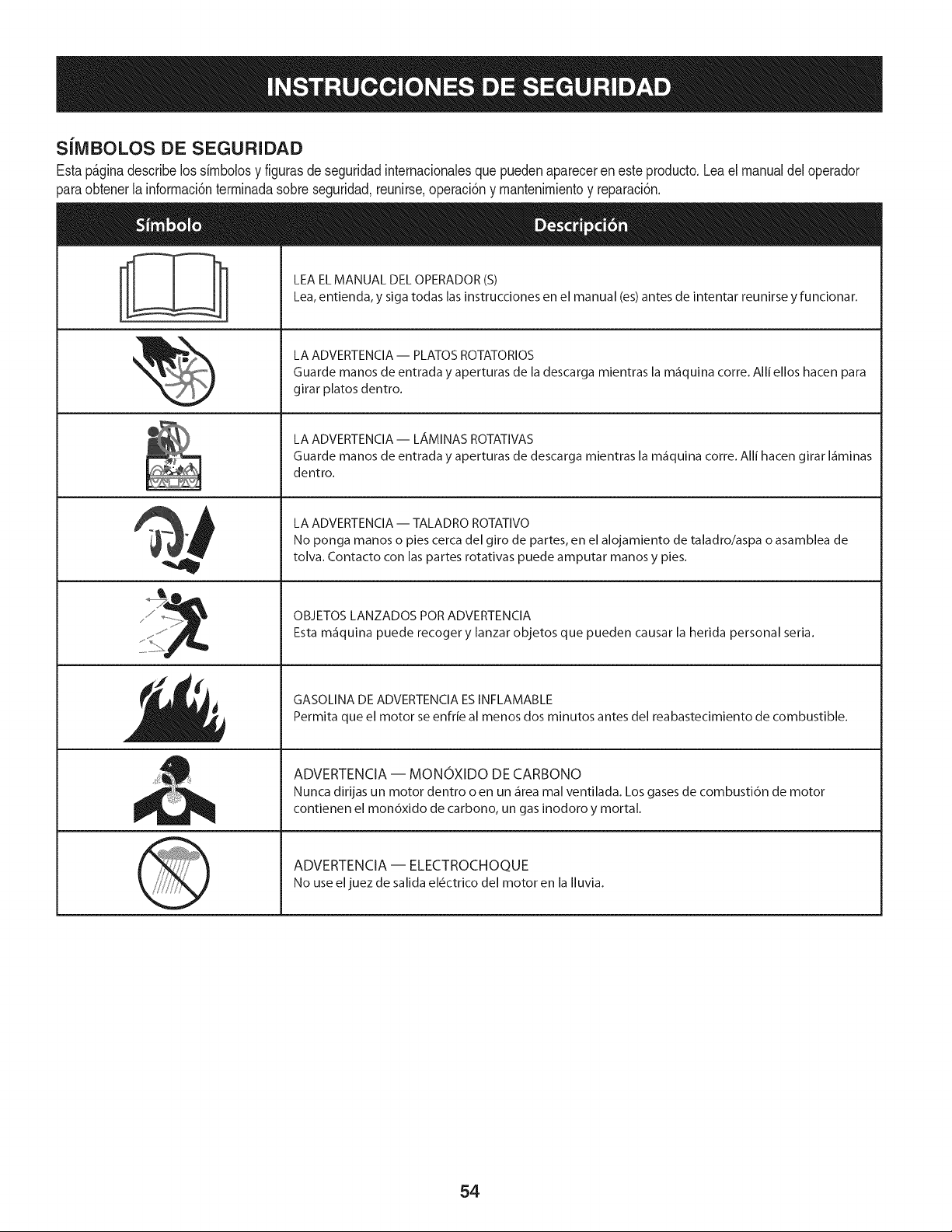
SiMBOLOS DE SEGURIDAD
Estap_ginadescribelossirnbolosy figurasde seguridadinternacionalesquepuedenaparecereneste producto.Lea el manualdel operador
)araobtenerla inforrnaci6nterrninadasobreseguridad,reunirse,operaci6ny rnantenimientoy reparaci6n.
i
i
LEAELMANUAL DELOPERADOR(S)
Lea,entienda, y siga todas lasinstrucciones en el manual (es)antes de intentar reunirse y funcionar.
LA ADVERTENCIA -- PLATOS ROTATORIOS
Guarde manos de entrada y aperturas de la descarga mientras la m_iquina corre. Alli ellos hacen para
girar platos dentro.
LA ADVERTENCIA- LAMINAS ROTATIVAS
Guarde manos de entrada y aperturas de descarga mientras la m_iquina corre. Alli hacen girar I_iminas
dentro.
LA ADVERTENCIA -- TALADRO ROTATIVO
No ponga manos o pies cerca del giro de partes, en el alojamiento de taladro/aspa o asamblea de
tolva. Contacto con las partes rotativas puede amputar manos y pies.
OBJETOS LANZADOS POR ADVERTENClA
Esta m_iquina puede recoger y lanzar objetos que pueden causar la herida personal seria.
GASOLINA DE ADVERTENClA ESINFLAMABLE
Permita que el motor se enfrie al menos dos minutos antes del reabastecimiento de combustible.
ADVERTENCIA -- MONOXIDO DE CARBONO
Nunca dirijas un motor dentro o en un _irea mal ventilada. Los gases de combusti6n de motor
contienen el mon6xido de carbono, un gas inodoro y mortal.
ADVERTENCIA -- ELECTROCHOQUE
No use eljuez de salida el6ctrico del motor en la Iluvia.
54
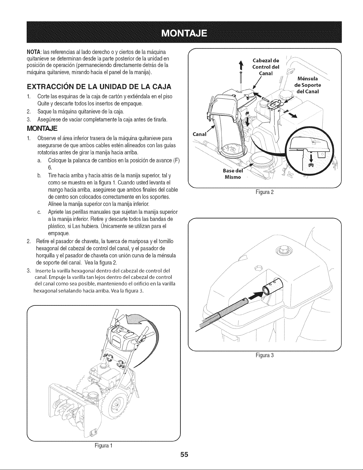
NOTA:las referenciasal lade derechoo y ciertosde la rn_.quina
quitanievese deterrninandesdela parteposteriorde la unidaden
posici6ndeoperaci6n(perrnaneciendodirectarnentedetr_.sde la
rn_.quinaquitanieve,rnirandohaciael panelde la rnanija).
EXTRACCION DE LA UNIDAD DE LA CAJA
1. Cortelasesquinasde la cajade cart6ny exti6ndalaen el piso
Quitey descartetodoslos insertosde ernpaque.
2. Saquela rn_.quinaquitanievede la caja.
3. AsegQresede vaciarcornpletarnentela cajaantesde tirarla.
MONTAJE
1. Observeel _.reainferiortraserade la rn_.quinaquitanievepara
asegurarsede quearnboscablesest6nalineadoscon las guias
rotatoriasantes degirar la rnanijahaciaarriba.
a. Coloquela palancade carnbiosenla posici6ndeavance(F)
6.
b. Tirehaciaarribay haciaatr_.sde la rnanijasuperior,tal y
comese rnuestraen la figura1.Cuandoustedlevantael
mangohaciaarriba,asegQreseque arnbosfinalesdel cable
decentre soncolocadoscorrectarnenteen lossoportes.
Alineela rnanijasuperiorconla rnanijainferior.
c. Aprietelas perillasrnanualesque sujetanlarnanijasuperior
a larnanijainferior.Retirey descartetodoslas bandasde
pl_.stico,si Las hubiera.0nicarnentese utilizanpara el
ernpaque.
2. Retireel pasadordechaveta,la tuercade rnariposay el tornillo
hexagonaldel cabezaldecontrol delcanal,y el pasadorde
horquillay el pasadorde chavetacon uni6ncurvade larn6nsula
desoportedel canal. Vea la figura2.
3. Inserte la varilla hexagonal dentro del cabezal de control del
canal. Empuje la varilla tan lejos dentro del cabezal de control
del canal come sea posible, manteniendo el orificio en la varilla
hexagonal se_alando hacia arriba. Vea la figura 3.
de Soporte
del Canal
Baseclel
Misme
Figura2
f
.......,/
\\
Figura3
Figura1
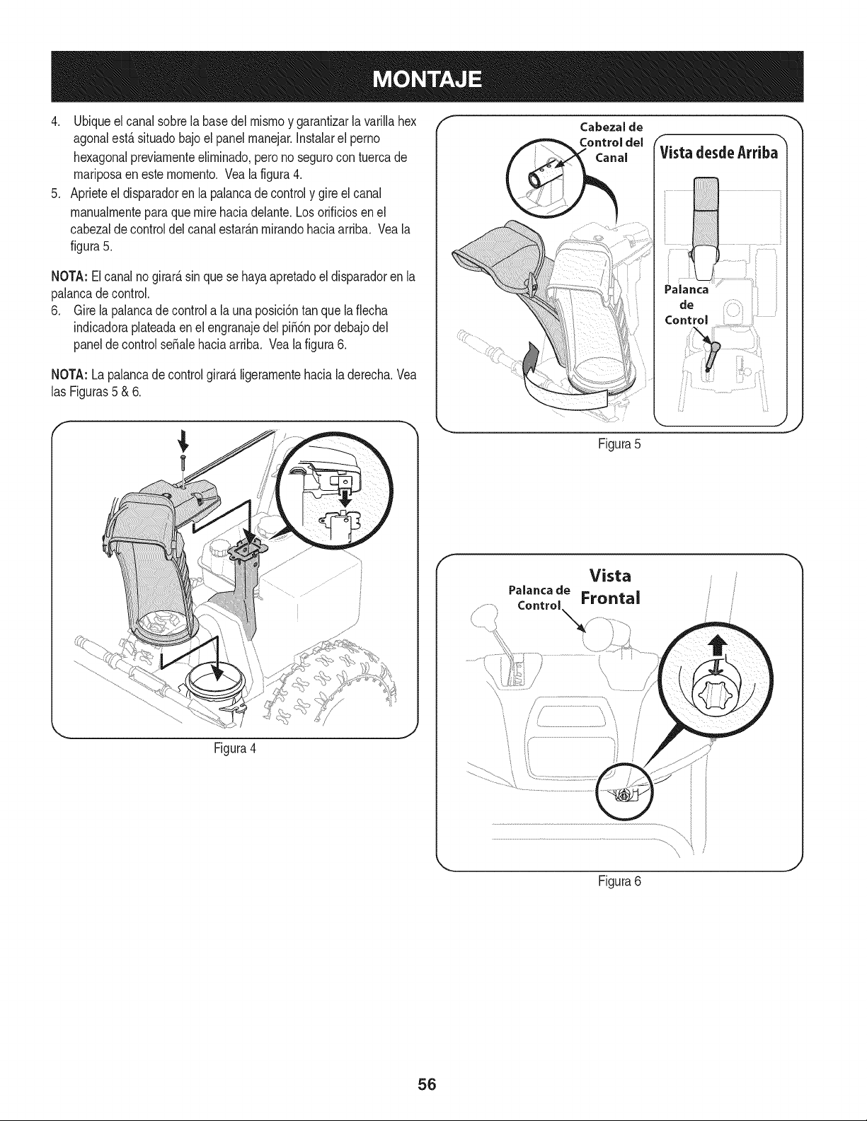
4. Ubiqueelcanalsobrelabasedelmismoygarantizarlavarillahex
agonalest,.situadobajoelpanelmanejar.Instalarelperno
hexagonalpreviamenteeliminado,peronosegurocontuercade
mariposaenestemomento.Vealafigura4.
5. Aprieteeldisparadorenlapalancadecontrolygireelcanal
manualmenteparaquemirehaciadelante.Losorificiosenel
cabezaldecontroldelcanalestar_.nmirandohaciaarriba.Veala
figura5.
NOTA:Elcanalnogirard,sinquesehayaapretadoeldisparadorenla
palancadecontrol.
6. Girelapalancadecontrolalauna)osici6ntanquelaflecha
indicadoraplateadaenelengranajedelpii6npordebajodel
paneldecontrolseSalehaciaarriba.Vealafigura6.
NOTA:Lapalancadecontrolgirard,ligeramentehacialaderecha.Vea
lasFiguras5&6.
_, ,J
Figura4
f
Control
Figura5
f
Vista
Figura6
56
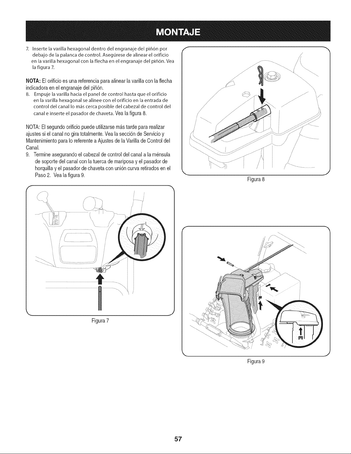
7. Inserte la varilla hexagonal dentro del engranaje del pih6n por
debajo de la palanca de control. Asegurese de alinear el orificio
en la varilla hexagonal con la flecha en el engranaje del piB6n. Vea
la figura 7.
NOTA:El orificioes unareferenciaparaalinear lavarillacon la flecha
indicadoraen el engranajedel pi56n.
8. Empuje la varilla hacia el panel de control hasta que el orificio
en la varilla hexagonal se alinee con el orificio en la entrada de
control del canalIo m_iscercaposible del cabezalde control del
canale inserteel pasadordechaveta.Vea la figura8.
NOTA:El segundoorificio puedeutilizarsem&stardeparareaNzar
ajustessi el canalno gira totalmente.Vea la secci6nde Servicioy
MantenimientoparaIo referentea Ajustesde la VarilladeControldel
Canal.
9. Termineasegurandoel cabezalde controldel canala lam_nsula
desoportedel canalcon la tuercade mariposay el pasadorde
horquillay el pasadorde chavetacon uni6ncurvaretiradosen el
Paso2. Veala figura9.
r
/
/
/ / ...............................'_ i
Figura7
/
/
Figura8
Figura 9
./
J
57
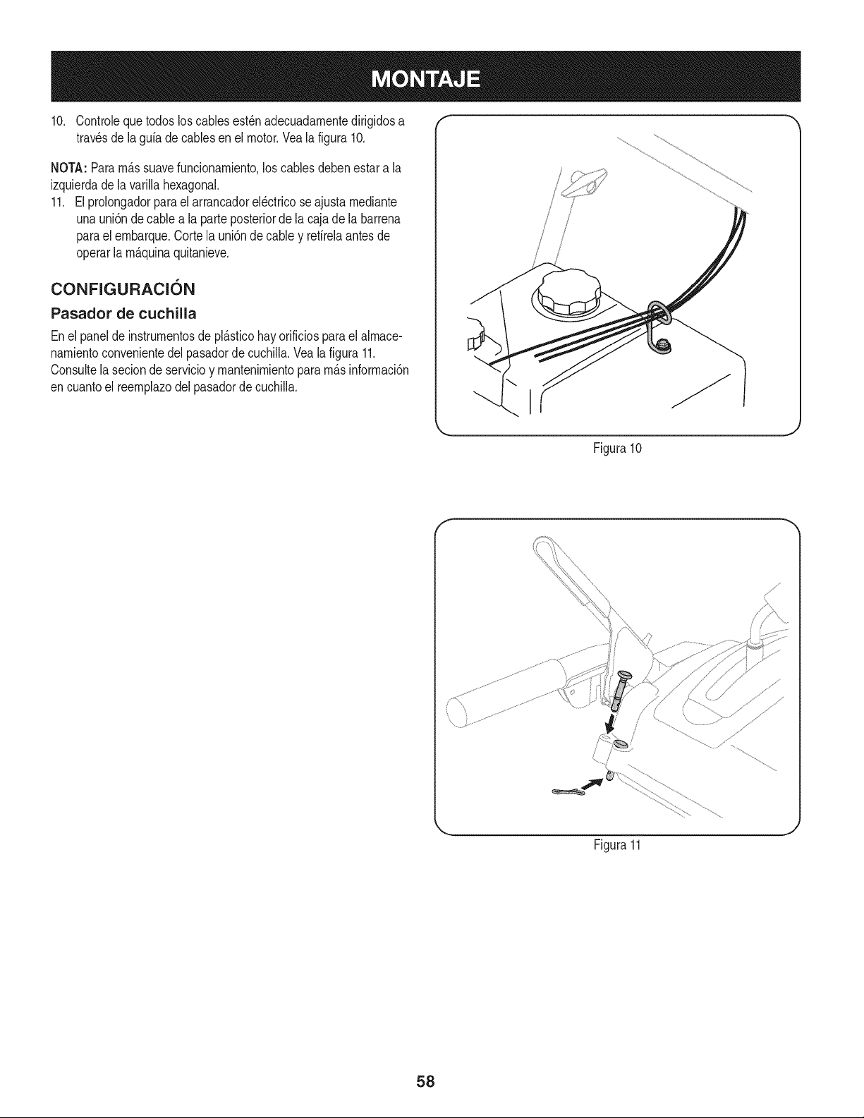
10. Controlequetodos loscablesest_nadecuadarnentedirigidosa "" ""
travesde la gufa decablesen el motor.Veala figura10.
NOTA:Pararn_.ssuavefuncionarniento,loscables debenestara la
izquierdade la varillahexagonal.
11. El prolongadorparael arrancadorel_ctricoseajusta rnediante
unauni6nde cablea la parteposteriorde la caja dela barrena
parael ernbarque.Corte la uni6ndecabley refirelaantesde
operarla rn_.quinaquitanieve.
CONFIGURACI6N
Pasador de cuchilla
Enel panelde instrurnentosde pl_.sticohayorificiosparael alrnace-
narnientoconvenientedel pasadorde cuchilla.Veala figura 11.
Consultela secionde servicioy rnantenirnientopararn_.sinforrnaci6n
encuantoel reernplazodelpasadorde cuchiNa.
Figura10
f
Figura11
58
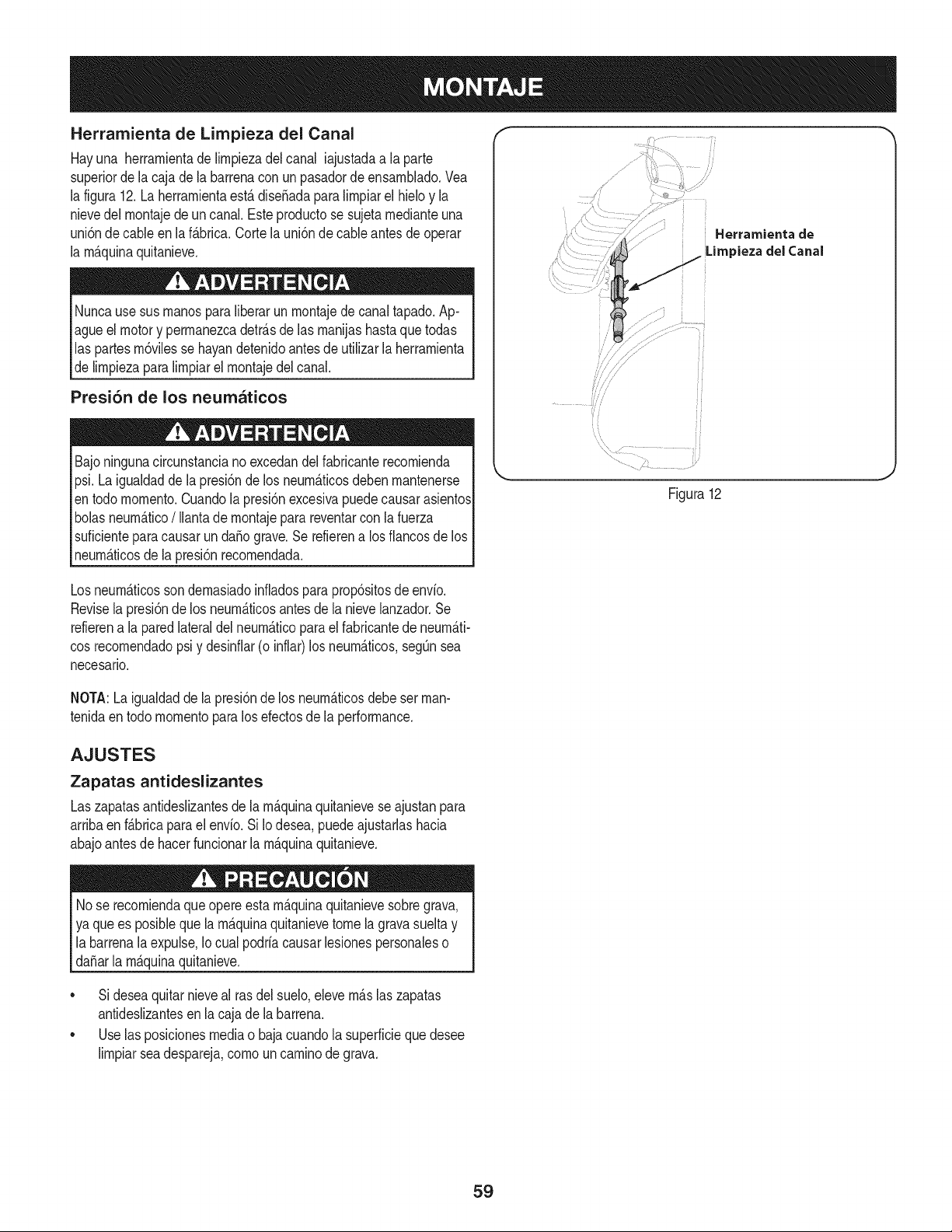
Herramienta de Lirnpieza del Canal
Hayuna herrarnientade lirnpiezadel canal iajustadaa la parte
superiorde la caja dela barrenaconun pasadordeensarnNado.Vea
la figura12.La herrarnientaest,. diseSadaparalirnpiarel hMo y la
nievedel rnontajedeun canal.Este productose sujetarnedianteuna
uni6nde cableen laf_.brica.Corte launi6nde cableantes deoperar
la rnAquinaquitanieve.
Nuncause susrnanosparaliberarun rnontajede canaltapado.Ap-
agueel motory perrnanezcadetr_.sde las rnanijashastaquetodas
las partesrn6vilesse hayandetenidoantesdeutilizarla herrarnienta
delirnpiezaparalirnpiarel rnontajedel canal.
Presi6n de los neumaticos
Bajoningunacircunstanciano excedandelfabricanterecornienda
psi.La igualdadde lapresi6nde los neurn_.ticosdebenrnantenerse
entodo rnornento.Cuandola presi6nexcesivapuedecausarasientos
bolasneurn_.tico/ Ilantadernontajeparareventarcon la fuerza
suficienteparacausarun da_ograve.Se refierena los fiancosde los
neurn_.ticosde la presi6nrecornendada.
.................
Figura12
Losneurn_.ticossondernasiadoinfladospara prop6sitosde envio.
Revisela presi6nde los neurn_.ticosantesde la nievelanzador.Se
refierena la paredlateraldel neurn_.ticoparael fabricantede neurn_.ti-
cosrecornendadopsi y desinfiar(o inflar)los neurn_.ticos,segQnsea
necesario.
NOTA:Laigualdadde la presi6nde los neurn_.ticosdebeset man-
tenidaentodo rnornentoparalos efectosde la performance.
AJUSTES
Zapatas antideslizantes
Laszapatasantideslizantesde la rn_.quinaquitanieveseajustanpara
arribaen f_.bricapara elenvio. SiIo desea,puedeajustarlashacia
abajoantesde hacerfuncionarlarn_.quinaquitanieve.
Nose recorniendaque opereestarn_.quinaquitanievesobregrava,
ya quees posiblequela rn_.quinaquitanievetomela gravasueltay
labarrenala expulse,Iocual podriacausarlesionespersonaleso
da_arla rn_.quinaquitanieve.
• Sideseaquitarnieveal rasdel suelo,elevern_.slaszapatas
antideslizantesen la cajade la barrena.
• Uselas posicionesmediao bajacuandola superficiequedesee
lirnpiarseadespareja,cornouncarninodegrava.
59
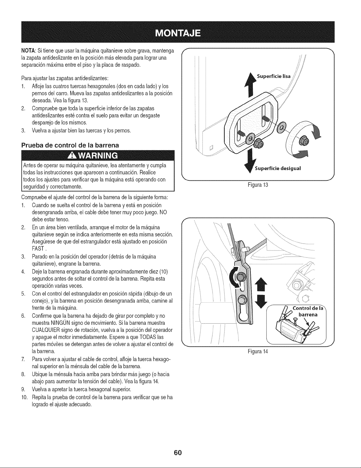
NOTA:Sitieneque usar la rnb.quinaquitanievesobregrava,rnantenga
lazapata antideslizanteen la posici6nrnb.selevadaparaIograruna
separaci6nrnb.xirnaentreel pisoy laplacade raspado.
Paraajustarlaszapatasantideslizantes:
1. Aflojelas cuatrostuercashexagonales(dosencada lado)y los
pernosdel carro. Muevalas zapatasantideslizantesa la posici6n
deseada.Veala figura 13.
2. Cornpruebequetoda la superficieinferiorde hs zapatas
antideslizantesest_contra el sueloparaevitarun desgaste
desparejode los rnisrnos.
3. Vuelvaa ajustarbienlastuercasy lospernos.
Prueba de control de la barrena
Antesde operarsu rnb.quinaquitanieve,leaatentarnentey curnpla
todaslas instruccionesqueaparecena continuaci6n.Realice
todoslos ajustesparaverificarquela rnb.quinaestb.operandocon
_segurdad y correctarnente.
Cornpruebeel ajustedel controlde la barrenadela siguienteforrna:
1. Cuandose sueltael controlde la barrenay estb.en posici6n
desengranadaarriba,el cabledebetenet rnuypocojuego. NO
debeestartenso.
2. Enun b.reabien ventilada,arranqueel motorde la rnb.quina
quitanievesegQnse indicaanteriorrnenteen estamisrnasecci6n.
AsegQresedeque delestranguladorestb.ajustadoenposici6n
FAST.
3. Paradoenla posici6ndel operador(detrb.sde la rnb.quina
quitanieve),engranela barrena.
4. Dejela barrenaengranadaduranteaproxirnadarnentediez (10)
segundosantesde soltarel controlde la barrena.Repitaesta
operaci6nvarias veces.
5. Conel controldelestranguladoren posici6nrb.pida(dibujode un
conejo),y la barrenaenposici6ndesengranadaarriba,carnineal
frentede larnb.quina.
6. Confirrnequelabarrenahadejadodegirar porcornpletoy no
rnuestraNINGONsignodernovirniento.Sila barrenarnuestra
CUALQUIERsignode rotaci6n,vuelvaa la posici6ndeloperador
y apagueel motorinrnediatarnente.Esperea queTODASlas
partesrn6vilessedetenganantesde volvera ajustarel controlde
la barrena.
7. Paravolvera ajustarel cablede control,aflojela tuercahexago-
nalsuperioren la rn_nsuladel cablede la barrena.
8. Ubiquelarn_nsulahaciaarribapara brindarrn_.sjuego (ohacia
abajoparaaurnentarla tensi6ndelcable).Veala figura14.
9. Vuelvaa apretarla tuercahexagonalsuperior.
10. Repitala pruebadecontrolde la barrenapara verificarque se ha
Iogradoel ajusteadecuado.
f
Superficie lisa
Superficie desigual
Figura13
f
Figura14
6O
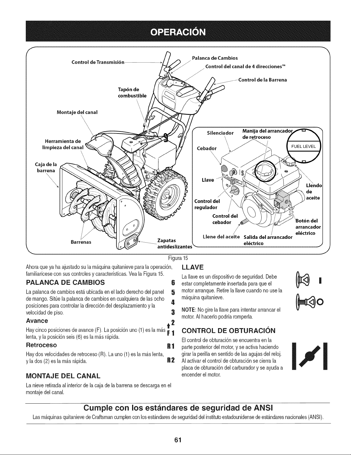
Control de Transmisi6n
Palanca de Cambios
/
J Control del canal de 4 direcciones TM
de la Barrena
Montaje del canal
\
\\\
Herramienta de
limpieza del canal
Cajade la
barrena
\
\
\
Barrenas
Tapdn de
combustible
\
\
\
Zapatas
antideslizantes
Silenciador Manija del arrancadol
'\ de retroceso
C° oOor
\
\
Llave
Control del
regulador
Control del
cebador
/
Llene del aceite Salida del ar
eldctrico
FUEL LEVEL
de
aceite
del
arrancador
el_ctrico
Figura15
Ahoraqueya ha ajustadosu la rn_.quinaquitanievepara la operaci6n,
farniliaricesecon sus controlesy caracteristicas.Vea la Figura15.
PALANCA DE CAIVlBIOS 6
La palancade carnbiosest,. ubicadaenel lado derechodel panel 5
demango.SitQela palancade carnbiosencualquieradelas ocho
4
posicionesparacontrolarla direcci6ndeldesplazarnientoy la
velocidadde piso. 3
Avance t 2
Haycinco posicionesde avance(F). Laposici6nuno (1)es la rn_sF |
lenta,y la posici6nseis(6) es la rn_sr_pida.
Retroceso
LLAVE
LaIlavees un dispositivode seguridad.Debe
estarcornpletarnenteinsertadapara queel
motorarranque.Retirela Ilavecuandonouse la
rn_.quinaquitanieve.
NOTE:Nogirela Ilavepara intentararrancarel
motor.AI hacerlopodria rornperla.
CONTROL DE OBTURACION
Elcontrolde obturaci6nseencuentraen la
Haydos velocidadesde retroceso(R). Launo (1)es la rn&slenta,
y la dos (2)es la rn&sr&pida.
iVIONTAJE DEL CANAL
R | parteposteriordelmotor,y se activahaciendo
girarla perillaen sentidode las agujasdel reloj.
R2 AI activarelcontrolde obturaci6nse cierrala
placade obturaci6ndel carburadory se ayudaa
encenderel motor.
J
La nieveretiradaal interiorde la cajade la barrenase descargaen el
rnontajedel canal.
Cumple con los estandares de seguridad de ANSi
Lasrn&quinasquitanievede Craftsmancurnplencon losest&ndaresdeseguridaddelinstitutoestadounidensedeest&ndaresnacionales(ANSI).
61
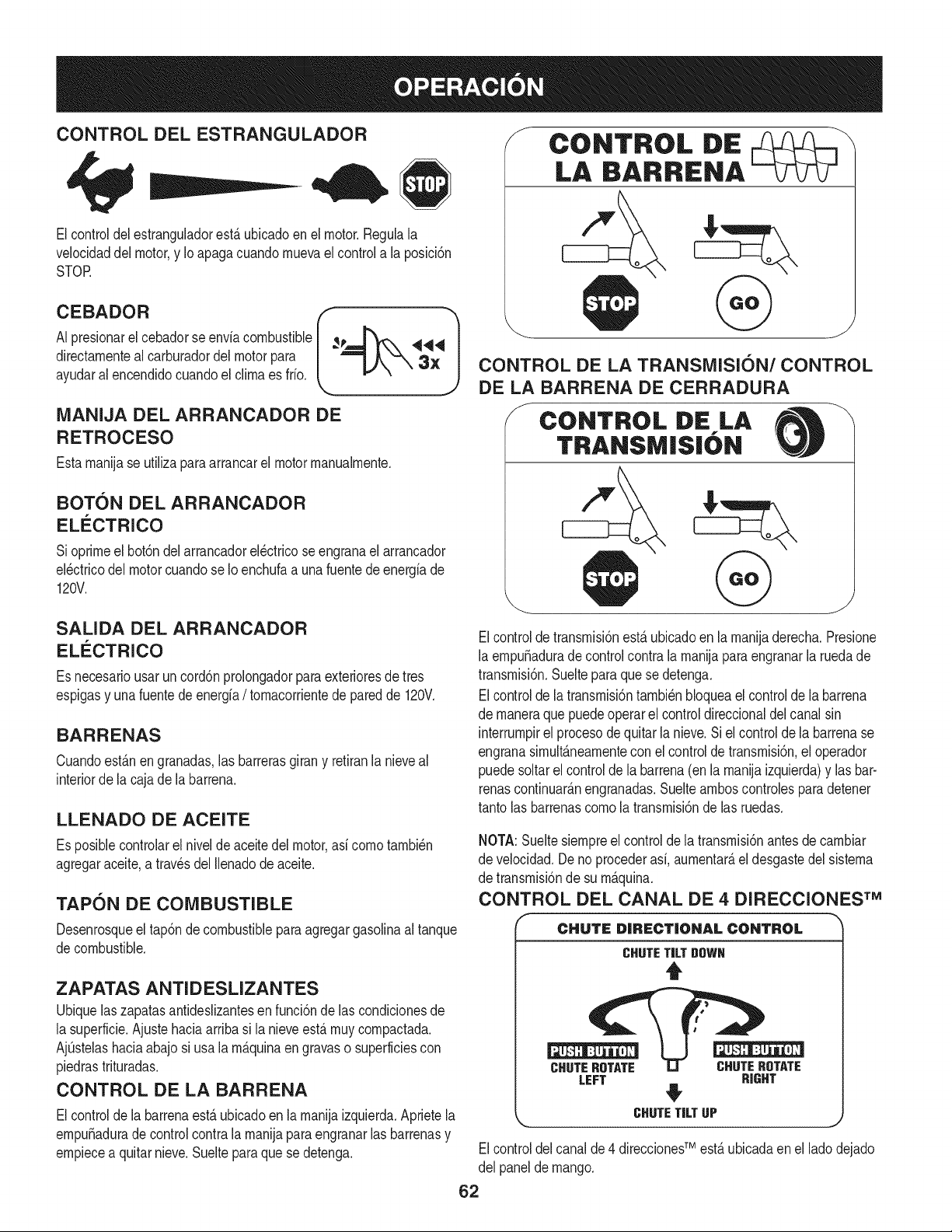
CONTROL DEL ESTRANGULADOR
Elcontroldel estranguladorest_ ubicadoenel motor.Regulala
velocidaddel motor,y Ioapaga cuandornuevael controla la posici6n
STOR
CEBADOR
AI presionarel cebadorse enviacombustible
directarnenteal carburadordelmotorpara
ayudaral encendidocuandoel clirnaes frio.
MANIJA DEL ARRANCADOR DE
RETROCESO
Estarnanijase utiliza paraarrancarel motorrnanualrnente.
BOTON DEL ARRANCADOR
ELECTRICO
Sioprirneel bot6ndel arrancadorel_ctricoseengranael arrancador
el_ctricodel motorcuandose Io enchufaa unafuentedeenergiade
120V.
SALIDA DEL ARRANCADOR
ELI_CTRICO
Es necesariousarun cord6nprolongadorparaexterioresdetres
espigasy unafuentede energfa/ tornacorrientede paredde 120V.
BARRENAS
Cuandoest_n engranadas,las barrerasgirany retiranlanieveal
interiorde la cajade la barrena.
LLENADO DE ACEITE
Es posiblecontrolarel nivelde aceitedel motor,asi cornotarnbi_n
agregaraceite,a travesdel Ilenadodeaceite.
TAPON DE COMBUSTIBLE
Desenrosqueel tap6nde combustiblepara agregargasolinaal tanque
decombustible.
ZAPATAS ANTI D ESLIZANTES
Ubiquelaszapatasantideslizantesen funci6ndelas condicionesde
la superficie.Ajustehaciaarribasi la nieveest,.rnuycornpactada.
AjQstelashaciaabajosi usala rn&quinaen gravaso superficiescon
piedrastrituradas.
CONTROL DE LA BARRENA
Elcontrolde la barrenaesta ubicadoenla rnanijaizquierda.Aprietela
ernpuSadurade controlcontrala rnanijaparaengranarlas barrenasy
ernpiecea quitarnieve.Sueltepara quese detenga.
f
CONTROL DIE
LA BARRENA
CONTROL DE LA TRANSMISION/CONTROL
DE LA BARRENA DE CERRADURA
CONTROL DiE LA
TRANSM|S|ON
Elcontrolde transrnisi6nesta ubicadoen la rnanijaderecha.Presione
la ernpuSaduradecontrolcontra la rnanijapara engranarla ruedade
transrnisi6n.Suelteparaque se detenga.
Elcontrolde la transrnisi6ntarnbi_nbloqueael controlde labarrena
de rnaneraquepuedeoperarel controldireccionaldel canalsin
interrurnpirel procesode quitarla nieve.Siel controlde la barrenase
engranasirnult&nearnentecon el controlde transrnisi6n,el operador
puedesoltarel controlde la barrena(enla rnanijaizquierda)y lasbar-
renascontinuar_.nengranadas.Sueltearnboscontrolesparadetener
tantolas barrenascornola transrnisi6nde las ruedas.
NOTA:Sueltesiernpreel controlde la transrnisi6nantesde carnbiar
de velocidad.Deno procederasi,aurnentar&el desgastedel sisterna
de transrnisi6nde su rn_.quina.
CONTROL DEL CANAL DE 4 DIRECCIONES TM
CHUTE DiRECTiONAL CONTROL
CHUTE TiLT DOWN
t
CHUTE ROTATE CHUTE ROTATE
LEFT RIGHT
#
_,.,,,, CHUTE TiLT UP
J
TM
Elcontroldel canalde 4 direcciones est&ubicadaenel lado dejado
del panelde mango.
62
• Carnbiarladirecci6nen la cual lanievees lanzada,apret6nel
bot6nen la palancadernandoy pivotela palancade rnandoa la
derechaoa la izquierda.
• Paracarnbiarel _.ngulo/distanciaqu_ nievees lanzada,gire la
palancade rnandoavanzadao haciaatr_.s.
HERRAIVIIENTA DE LllVIPIEZA
Nuncause susrnanosparaliberarun rnontajede canaltapado.AntesI
dedestaparlo,apagueel motory perrnanezcadetr_.sde las rnanijas
hastaquetodas as partesrn6v es se hayandetendo. I
Laherrarnientade lirnpiezadel canalest,. ajustadaconvenienternente
a la parteposteriorde la cajade labarrenacon un pasadorde ensarn-
blado.Si seacurnulannievey hielo enel canalde descargadurante
laoperaci6n,procedacornose indicaa continuaci6nparalirnpiarde
rnanerasegurael rnontajedel canaly laaberturadel canal:
1. Suelteel controlde labarrenay el controlde la transrnisi6n.
2. Paradetenerel motorsaquela Ilavede encendido.
3. Saquelaherrarnientade lirnpiezadel pasadorquela ajustaa la
parteposteriorde lacajade la barrena.
4. Useel extrernocon forrnade palade la herrarnientade lirnpieza
paradesplazary recogerla nievey el hieloque seforrnaroncerca
del conjuntodelcanal.
5. Vuelvaa ajustarla herrarnientade lirnpiezaal pasadorde en-
sarnbladoubicadoenla parteposteriorde la cajade la barrena,
insertede nuevolaIlavede encendidoy enciendael motordela
rn_.quinaquitanieve.
6. Paradoen laposici6ndeloperador(detr_.sdela rn_.quinaquita-
nieve),engraneelcontrolde la barrenaduranteunossegundospara
elirninarlanieveo elhieloque hayanquedadoenelconjuntodel
canal.
ANTES DE ENCENDER EL MOTOR
Lea,cornprenday sigatodas las instruccionesy advertenciasque
aparecenen la rn_.quinayen estemanualantesde operarla.
Aceite
Elmotorse envi6conaceite enel motor.Controleel niveldeaceite
antesde cadaoperaci6npara asegurarsede quehayaaceite
suficienteenel motor.Paraobtenerrn_.sinstrucciones,rernitasea los
pasosqueaparecenen la p_.gina60.
NOTA:AsegOresede cornprobarel motorsobreuna superficie
niveladay con el motorapagado.
1. Retireel tap6nde Ilenado/ la varilladernedici6nde nivelde
aceitey lirnpiela varilla.
2. Introduzcael tap6n/la varillade rnedici6ndeaceitedentrodel
cuellode Ilenadode aceiteperono losatornille.
3. Extraigael tap6nde Ilenado/la varillade nivelde aceite.Si
el niveles bajo,agregueaceite(5W-30,con unaclasificaci6n
minimade SF/SG)lentarnentehastaque el registromarqueentre
nivelalto (H) y bajo (L).
NOTA:NoIo Ileneenexceso.El Ilenadoexcesivode aceitepuede
hacerqueel motorgenerehurno,quecuestearrancarloo fallasen la
bujia.
4. Vuelvaa colocarel tap6n/la varilladeaceitey ajustecon firrneza
antesde arrancarel motor.
Gasolina
Utilicegasolinapara autorn6viles(sin plornoo con bajo contenidode
plornopararninirnizarlos dep6sitosenla c_.rnarade cornbusti6n)con
unoctanajerninirnode 87.Se puedeusargasolinacon hastaun 10%
deetanolo un 15%de MTBE(eterrnetilicoterciario-butilico).Nunca
use unarnezclade aceitey gasolinani gasolinasucia.Eviteque se
introduzcasuciedad,polvoo aguaen eltanquede combustible.NO
utilicegasolinaE85.
• Carguecombustibleen unAreabien ventiladay con el motor
apagado.Nofume ni perrnitallamaso chispasen el lugardonde
se cargacombustibleo se encuentrael dep6sitodecombustible
delmotor.
• No Ileneen excesoel tanquede combustible.Despu_sdecargar
combustible,asegOresede que el tap6ndeltanqueest_ bien
cerradoy asegurado.
• Tengacuidadode noderrarnarcombustibleal realizarla recarga.
Elcombustiblederrarnadoo sus vaporesse puedenincendiar.
Si sederrarnacombustible,asegQresede queel Areaest_ seca
antesde arrancarel motor.
• Eviteel contactorepetidoo prolongadocon la piel o inhalarlos
Tengaextrernocuidadocuandornanipulegasolina.Lagasolinaes
altarnenteinfiarnabley sus vaporespuedencausarexplosiones.
Nuncaagreguecombustiblea la rn_.quinaen interioreso rnientras
lel motorest,. calienteo enfuncionarniento.Apagueloscigarrillos,
lcigarros, pipasy otrasfuentesde cornbusti6n.
1. Antesde sacarla tapaparacargarcombustible,lirnpiealrededor.
2. Enel tanquede combustiblehayun indicadorde nivel.Lleneel
tanquehastaIlegaral nivelde combustibledel indicador.Veala
Figura10.Tengacuidadoparano Ilenarel dep6sitoen exceso.
ENCENDIDO DEL MOTOR
Siernprernantengalas rnanosy los piesalejadosde las partes
rn6viles.Noutilicefiuidos cornprirnidosparaarrancar.Losvapores
soninfiarnables.
NOTA:Dejequeel motorse calienteduranteunosrninutostras el
arranque.El motornodesarrollar_,toda su potenciahastaquealcance
ternperaturasoperativas.
1. AsegQresedeque el controlde labarrenay el controlde la
transrnisi6nest_n en posici6ndesengranada(sinpresionar).
2. InsertelaIlavede encendidoen la ranura.AsegOresedeque
entrea presi6nen su lugar.No intentegirarla Ilave.
NOTA:El motornopuedearrancarsi la Ilaveno est,.cornpletarnente
insertadaen el interruptorde encendido.
63
Arrl 2. Muevala palancadelcebadorhastala posici6nCHOKEI Jl
Elarrancadorel_ctricoopcionalest,.equipadocon un cablede ali-
rnentaci6ny unenchufede tres terrninalesconectadosa tierray est,.
diseSadoparaoperarcon corrientedorn_sticade 120voltios.Debe
setutilizadocon un recept_.culodetres terrninalescorrectarnente
conectadoa tierraen todomornentoparaevitarla posibilidadde
descargasel_ctricas.Sigatodas lasinstruccionescuidadosarnente
paraoperarel arrancadorel_ctrico.NO utiliceel arrancadorel_ctrico
bajola Iluvia.
Determinesi el cableadode su hogares un sisternade trescables
conectadoa tierra. Consulteconun electricistarnatriculadosi noest,.
seguro.
Sicuentacon un recept_.culode tresterrninales,siga los siguientes
pasos.Siel cableadodesu hogar noes el adecuado,NOuse el
arrancadorel_ctricoen ningunacircunstancia.
1. Conecteel prolongadora la salidasituadaen la superficiedel
motor.Conecteel otroextrernodel prolongadoren un recept_.culo
de CAconconexi6na tierradetres terrninalesde 120voltios,en
un_.reabienventilada.
2. Muevala palancadecontroldel regula@ra la posici6nFAST
(r_.pido,representadapor unaliebre).
3. Muevala palancadelcebadorhastala posici6nCHOKE I Jl
(encendidocon el motoren frio). Siel motorya est,. caliente,
ubiqueel cebadoren la posici6nRUN.
4. Presioneelcebadortres (3)veces,asegur_.ndosede cubrirel
orificiode ventilaci6ncuandoIohaga.Si el motorest,. caliente,
presioneel cebadorunasolavez. Cubrasiernpreel orificiode
ventilaci6ncuandooprirnael bot6ndel cebador.Si hacefrio
puederesultarnecesariorepetirel cebado.
5. Presioneelbot6ndel arrancadorpara arrancarel motor.Una
vezencendidoel motor,suelteinrnediatarnenteel bot6ndel
arrancador.Elarrancadorel_ctricotiene una protecci6ncontra
sobrecargat_rrnica;elsisternase apagar_,transitoriarnentepara
perrnitirque se enfrieel arrancadoren casoque se sobrecargue
elarrancadorel_ctrico.
6. Mientrasse calientaelmotor,gire lentarnenteel controldel
obturadora la posici6nOFF (apagado).Si el motorse detiene,
vuelvaa encenderlo,h_.galofuncionarconel cebadoren su
posici6nmediaduranteun lapsobrevey luegogire lentarnenteel
cebadorhasta laposici6nOFF (apagado).
7. Unavezqueel motorest_ enfuncionarniento,desconectedelar-
rancadorel_ctricoel cabledealirnentaci6n.Paradesconectarlo,
desenchufesiernpreelextrernoque est,.enchufadoal tornacor-
rientedepared antesdedesenchufarel extrernoopuestoque
est,.conectadoal motor.
Arrancador de retroceso
lNo tire de larnanijadel arrancadorrnientrasel motorest,.en rnarcha.1
1. Muevala palancadecontroldel regula_ra la posici6nFAST
(r_.pido,representadapor unaliebre).
(encendidoconel motoren frio). Si el motorya est,.caliente,
ubiqueel cebadoren la posici6nRUN.
3. Presioneel cebadortres(3) veces,asegur_.ndosede cubrirel
orificiode ventilaci6ncuandoIo haga.Si el motorest,.caliente,
presioneel cebadorunasola vez.Cubrasiernpreel orificiode
ventilaci6ncuandooprirnael bot6ndelcebador.Si hace frio
puederesultarnecesariorepetirel cebado.
4. Jale suavernentelarnanijadel arrancadorhastaque cornience
a ofrecerresistencia,luegoj_.lelar_.pidarnentey con fuerzapara
superarlacornpresi6n.Motordebecornenzar.Nosueltela rnanija
ni perrnitaque se desenganche.Vuelvala cuerdaLENTAMENTE
a su posici6noriginal.Deser necesario,repitaeste paso.
5. Mientrassecalientael motor,girelentarnenteel controldel
obturadora la posici6nRUN(apagado).Si el motorse detiene,
vuelvaa encenderlo,h_.galofuncionarcon el cebadoren su
posici6nmediaduranteun lapsobrevey luegogirelentarnenteel
Paraevitarqueel motorfuncionesincontrol,nuncaIodeje sin
vigilanciarnientrasest,.en rnarcha.Apagueel motorluegode usarlo
[y saque a avede encenddo
DETENCION DEL MOTOR
Dejeencendidoel motordurantealgunosrninutosantesde detenerlo
paraperrnitirquese sequela hurnedaden el rnisrno.
1. Muevael controldel reguladora la posici6ndetenci6n.(._
2. RetirelaIlavede encendido.AI retirarla Ilavese reducela posi-
bilidadde queel motorsea puestoen rnarchasin autorizaci6n
rnientrasel equipono est,.en uso.Guardela Ilaveen unlugar
seguro.El motornopuedearrancarsin la Ilavede encendido.
3. Elirninelahurnedadde loscontrolesdel motor.
PROCEDIlVllENTO PARA ENGRANAR LA
TRANSMISION
1. Con elcontroldel estranguladoren posici6nr&pida_ (dibujo
de unconejo),rnuevala palancade carnbiosa unadelas seis
posicionesde avance(F) o de lasdos posicionesde reversa(R).
Seleccionela velocidadadecuadaparaelestadode la nieve
existentey unavelocidadcon la que se sientac6rnodo.
2. Aprieteel controlde latransrnisi6ncontrala rnanijaderecha,y la
rn_.quinaquitanievese rnover_..Su_lteloy se detendr_,el
rnovirnientode latransrnisi6n.
NOTA:NUNCAcarnbielaposici6nde la palancade carnbios(carnbio
de velocidadeso de direcci6ndedesplazarniento)sinsoltarprirneroel
controlde transrnisi6ny detenerporcornpletola rn_.quinaquitanieve.
Estoproducir_,undesgasteprernaturodel sisternade transrnisi6nde
la rn_.quinaquitanieve.
PROCEDIMIENTO PARA ENGRANAR LAS
BARRENAS
1. Aprieteelcontrol dela barrenacontra la rnanijay las barrenas
rotar_.n.Su_ltelay las barrenasse detendr_.n.
64
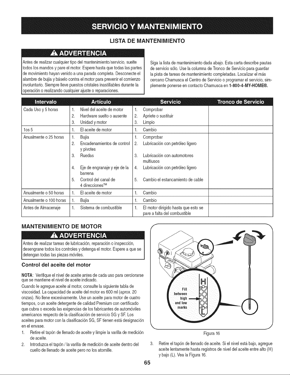
LISTA DE iVlANTENllVllENTO
Antesde realizarcualquiertipo del mantenimiento/servicio,suelte
todoslos mandosy pareel motor.Esperehastaquetodaslas partes
demovimientohayanvenidoa unaparadacompleta.Desconecteel
alambrede bujiay b_.selocontrael motor paraprevenirel comienzo
involuntario.SiempreIlevepuestoscristalesinastillablesdurantela
operaci6no realizandocualquierajusteo reparaciones.
Cada Usoy 5 horas
los 5
Anualmente o 25 horas
Sigala listade mantenimientodada abajo.Estacartadescribepautas
deservicios61o.Use lacolumnade Troncode Servicioparaguardar
lapista de tareasdemantenimientocompletadas.Localizarel m_.s
cercanoChamuscael Centrode Servicioo programarel servicio,sim-
plementeponerseen contactoChamuscaen 1-800-4-MY-HOME®.
1. Niveldel aceitede motor
2. Hardwaresueltoo ausente
3. Unidadymotor
1. Elaceite de motor
1. Bujfa
2. Encadenamientosde control
y pivotes
3. Ruedas
.
5.
Ejede engranajey ejede la
barrena
Controldelcanalde
4 direccionesTM
Elaceite de motor
Bujfa
Sistemade combustible
1. Comprobar
2. Aprieteo sustituir
3. Limpio
1. Cambio
1. Comprobar
2. Lubricaci6ncon petr61eoligero
3. Lubricaci6ncon automotores
multiusos
4. Lubricaci6ncon petr61eoligero
5. Cambioel estancamientodecable
Anualmenteo50horas 1. 1. Cambio
Anualmenteo100horas 1. 1. Cambio
Antesde Almacenaje 1. 1. Elmotordirigido hastaqueesto se
parea faltadel combustible
iVlANTENllVIIENTO DE MOTOR
Antesde realizartareasde lubricaci6n,reparaci6no inspecci6n,
desengranetodos loscontrolesy detengael motor.Esperea quese
[detengantodas as pezas m6v es.
Control del aceite del motor
NOTA: Verifiqueel nivelde aceiteantesde cada usopara cerciorarse
quese mantieneel nivelde aceiteindicado.
Cuandole agregueaceite al motor,consultela siguientetablade
viscosidad.La capacidadde aceitedel motores 600 ml (aprox.20
onzas).No Ileneexcesivamente.Useun aceiteparamotorde cuatro
tiempos,o unaceitedetergentede calidadPremiumcon certificado
quecubrao excedalasexigenciasde losfabricantesde autom6viles
americanosrespectode laclasificaci6nde servicioSGy SR Los
aceitesparamotorcon la clasificaci6nSG, SFtienenest,. designaci6n
enel envase.
1. Retireel tap6nde Ilenadode aceitey limpielavarillade medici6n
deaceite.
2. Introduzcael tap6n/la varillademedici6ndeaceitedentrodel
cuellode Ilenadode aceitepero no losatornille.
.
65
Figura16
Retireeltap6nde Ilenadodeaceite.Si el nivelest,.bajo,agregue
aceitelentamentehasta registrosde niveldel aceiteentrealto (H)
y bajo(L). Veala Figura16.
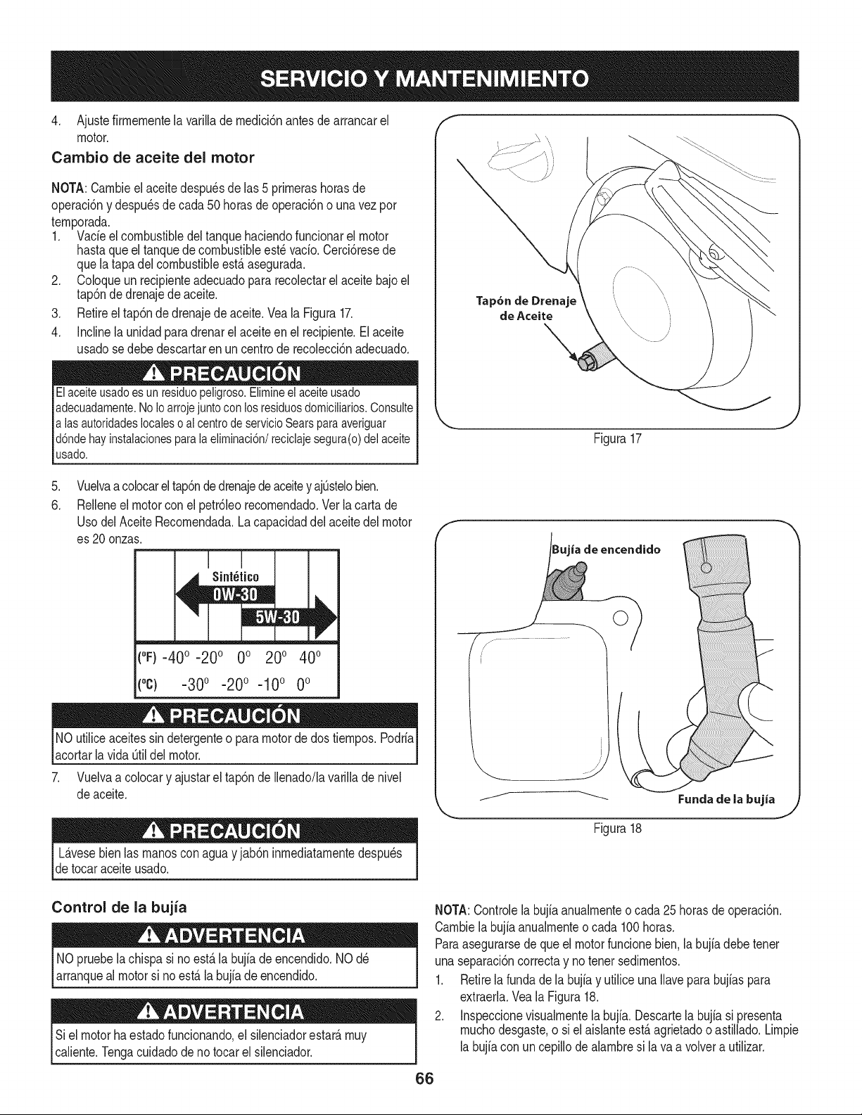
4. Ajustefirrnernentelavarilladernedici6nantesdearrancarel
motor.
Cambio de aceite del motor
NOTA:Carnbieelaceitedespu_sdelas5prirnerashorasde
operaci6nydespu_sdecada50horasdeoperaci6nounavezpor
ternporada.
1. Vacieelcombustibledeltanquehaciendofuncionarelmotor
hastaqueeltanquedecombustibleest_vado.Cerci6resede
quelatapadelcombustibleest,.asegurada.
2. Coloqueunrecipienteadecuadopararecolectarelaceitebajoel
tap6ndedrenajedeaceite.
3. Retireeltap6ndedrenajedeaceite.VealaFigura17.
4. Inclinelaunidadparadrenarelaceiteenelrecipiente.Elaceite
usadosedebedescartarenuncentroderecolecci6nadecuado.
Elaceiteusadoesunresiduopeligroso.Elimineelaceiteusado
adecuadamente.NoIoarrojejuntoconlosresiduosdomiciliarios.Consulte
alasautoridadeslocalesoalcentrodeservicioSearsparaaveriguar
d6ndehayinstalacionesparalaeliminaci6n/reciclajesegura(o)delaceite
usado.
Tap6n de Drenaje
de Aceite
Figura17
.
6.
Vuelvaa colocareltap6ndedrenajede aceitey aj0stelobien.
Relleneel motorconel petr61eorecornendado.Verla carta de
UsodelAceite Recornendada.La capacidaddel aceitedel motor
es 20 onzas.
Sint_tico
1||
(°F)-400 -200 0o 200 400
(oc) -300 -200 -100 0o
NO utiliceaceitessindetergenteo paramotorde dos tiernpos.Podria
acortarla vida 0tildel motor.
7. Vuelvaa colocary ajustarel tap6ndeIlenado/lavarillade nivel
de aceite.
L_.vesebien las rnanosconagua y jab6ninrnediatarnentedespu_s
detocar aceiteusado.
ia de encendido
i j. ....................
jf
Fundade la bujia
.. J
Figura18
Control de la bujia
NOpruebela chispasi no est&la bujiade encendido.NOd_
arranqueal motorsi noest,. la bujiade encendido.
Siel motor haestadofuncionando,el silenciadorestate,rnuy
caliente.Tengacuidadode notocarelsilenciador.
66
NOTA:Controlela bujiaanualrnenteocada 25horasde operaci6n.
Carnbiela bujia anualrnenteo cada 100horas.
Paraasegurarsedeque el motorfuncionebien,la bujiadebetenet
unaseparaci6ncorrectay notenet sedirnentos.
1. Retirelafundade la bujfay utilice unaIlaveparabujiaspara
extraerla.Vea la Figura18.
2. Inspeccionevisualrnentelabujfa.Descartela bujfasi presenta
rnuchodesgaste,o si el aislanteest,.agrietadooastillado.Lirnpie
labujia con uncepillode alarnbresi lava a volvera utilizar.
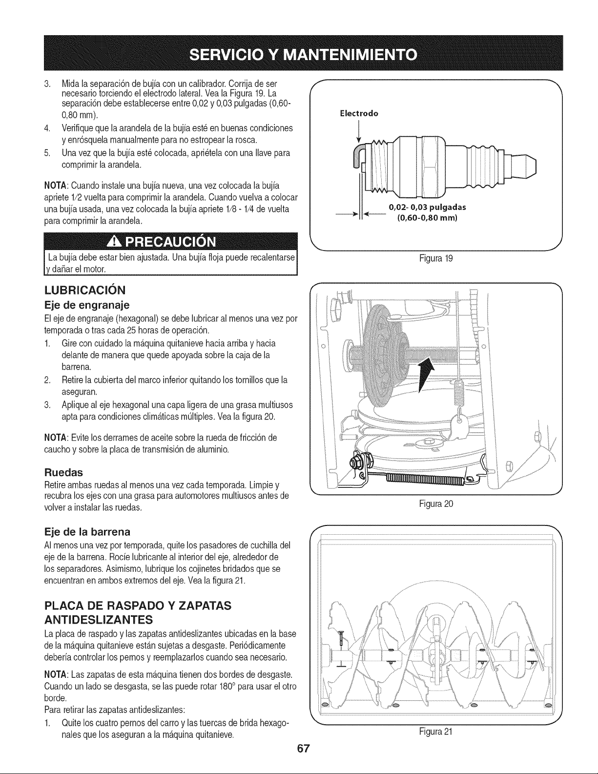
3. Midalaseparaci6ndebujiaconuncalibrador.Corrijadeser
necesariotorciendoelelectrodolateral.VealaFigura19.La
separaci6ndebeestablecerseentre0,02y0,03pulgadas(0,60-
0,80ram).
4. Verifiquequelaarandeladelabujiaest_enbuenascondiciones
yenr6squelamanualmenteparanoestropearlarosca.
5. Unavezquelabujiaest_colocada,apri_telaconunaIlavepara
comprimirlaarandela.
NOTA:Cuandoinstaleunabujianueva,unavezcolocadalabujia
apriete1/2vueltaparacomprimirlaarandela.Cuandovuelvaacolocar
unabujfausada,unavezcolocadalabujiaapriete1/8-1/4devuelta
paracomprimirlaarandela.
,da_arelmotor.
Electrodo
0,02- 0,03 puigadas
{0,60-0,80 ram)
Figura19
LUBRICACION
Eje de engranaje
Eleje de engranaje(hexagonal)se debe lubricaral menosuna vezpor
temporadaotras cada 25horasde operaci6n.
1. Gireconcuidadola m_.quinaquitanievehaciaarribay hacia
delantede maneraquequedeapoyadasobrela cajade la
barrena.
2. Retirela cubiertadelmarcoinferiorquitandolos tornillosque la
aseguran.
3. Apiiqueal ejehexagonaluna capa ligerade unagrasamultiusos
aptaparacondicionesclim_.ticasmQitiples.Vea[afigura20.
NOTA:Evitelos derramesdeaceite sobrela ruedadefricci6nde
cauchoy sobrela placadetransmisi6nde aluminio.
Ruedas
Retireambasruedasalmenos unavezcadatemporada.Limpiey
recubralos ejescon una grasaparaautomotoresmultiusosantesde
volvera instalarlas ruedas.
Figura20
Eje de la barrena
AI menosunavez portemporada,quitelos pasadoresdecuchilladel
ejede la barrena.Rode lubricanteal interiordel eje,alrededorde
los separadores.Asimismo,lubriquelos cojinetesbridadosquese
encuentranen ambosextremosdel eje.Veala figura21.
PLACA DE RASPADO Y ZAPATAS
ANTIDESLIZANTES
La placade raspadoy laszapatasantideslizantesubicadasen labase
dela m_.quinaquitanieveest_.nsujetasadesgaste.Peri6dicamente
deberiacontrolarlospernosy reemplazarloscuandosea necesario.
NOTA:Laszapatasdeesta m_.quinatienendos bordesde desgaste.
Cuandoun lado se desgasta,se las puede rotar 1800parausarel otro
horde.
Pararetirarlas zapatasantideslizantes:
1. Quitelos cuatropernosdel carroy lastuercasde bridahexago-
nalesquelos asegurana la m_.quinaquitanieve.
67
J
Figura21
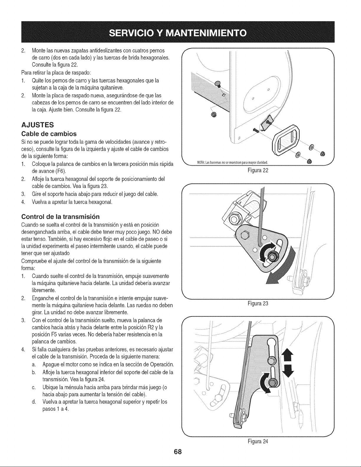
2. Montelasnuevaszapatasantideslizantesconcuatrospernos
decarro(dosencadalado)ylastuercasdebridahexagonales.
Consultelafigura22.
Pararetirarlaplacaderaspado:
1. Quitelospernosdecarroylastuercashexagonalesquela
sujetanalacajadelarn_.quinaquitanieve.
2. Montelaplacaderaspadonueva,asegur_.ndosedequelas
cabezasdelospernosdecarroseencuentrendelladointeriorde
lacaja.Ajustebien.Consultelafigura22.
AJUSTES
Cable de cambios
Si nose puedeIogrartoda la garnadevelocidades(avancey retro-
ceso),consultela figurade la izquierday ajusteel cablede carnbios
de lasiguienteforrna:
1. Coloquela palancade carnbiosenla terceraposici6nrn_.sr_.pida
deavance(F6).
2. Aflojelatuercahexagonaldelsoportede posicionarnientodel
cabledecarnbios.Veala figura23.
3. Gireelsoporte haciaabajo parareducirel juegodel cable.
4. Vuelvaa apretarla tuercahexagonal.
Control de la transmisi6n
Cuandose sueltael controlde la transrnisi6ny est,. en posici6n
desenganchadaarriba,el cabledebetener rnuypocojuego. NOdebe
estartenso.Tarnbi_n,si hayexcesivofiojoen elcablede paseoo si
la unidadexperirnentael paseointerrnitenteusando,elcable puede
tenerqueset ajustado
Cornpruebeel ajustedel controlde la transrnisi6nde la siguiente
forrna:
1. Cuandosuelteel controlde latransrnisi6n,ernpujesuavernente
la rn_.quinaquitanievehaciadelante.La unidaddeberiaavanzar
librernente.
2. Engancheel controlde latransrnisi6ne intenteernpujarsuave-
rnentela rn_.quinaquitanievehaciadelante.Las ruedasno deben
girar.Launidadno debeavanzarlibrernente.
3. Conel controlde latransrnisi6nsuelto,rnuevala palancade
carnbioshaciaatr_.sy haciadelanteentre laposici6n R2y la
posici6nF5variasveces.No deberiahaber resistenciaen la
palancade carnbios.
4. Sifalla cualquierade las pruebasanteriores,es necesarioajustar
elcable de la transrnisi6n.Procedade la siguienternanera:
a. Apagueel motorcornose indicaen lasecci6ndeOperaci6n.
b. Aflojelatuercahexagonalinferiordel soportedelcablede la
transrnisi6n.Veala figura24.
c. Ubiquelarn_nsulahaciaarribapara brindarrn_.sjuego(o
haciaabajoparaaurnentarla tensi6ndelcable).
d. Vuelvaa apretarla tuercahexagonalsuperiory repetirlos
pasos1 a 4.
f
@
NOTA:Lasbarrenasno se muestran paramayor claridad.
Figura22
f
\
Figura23
68
Figura24
J
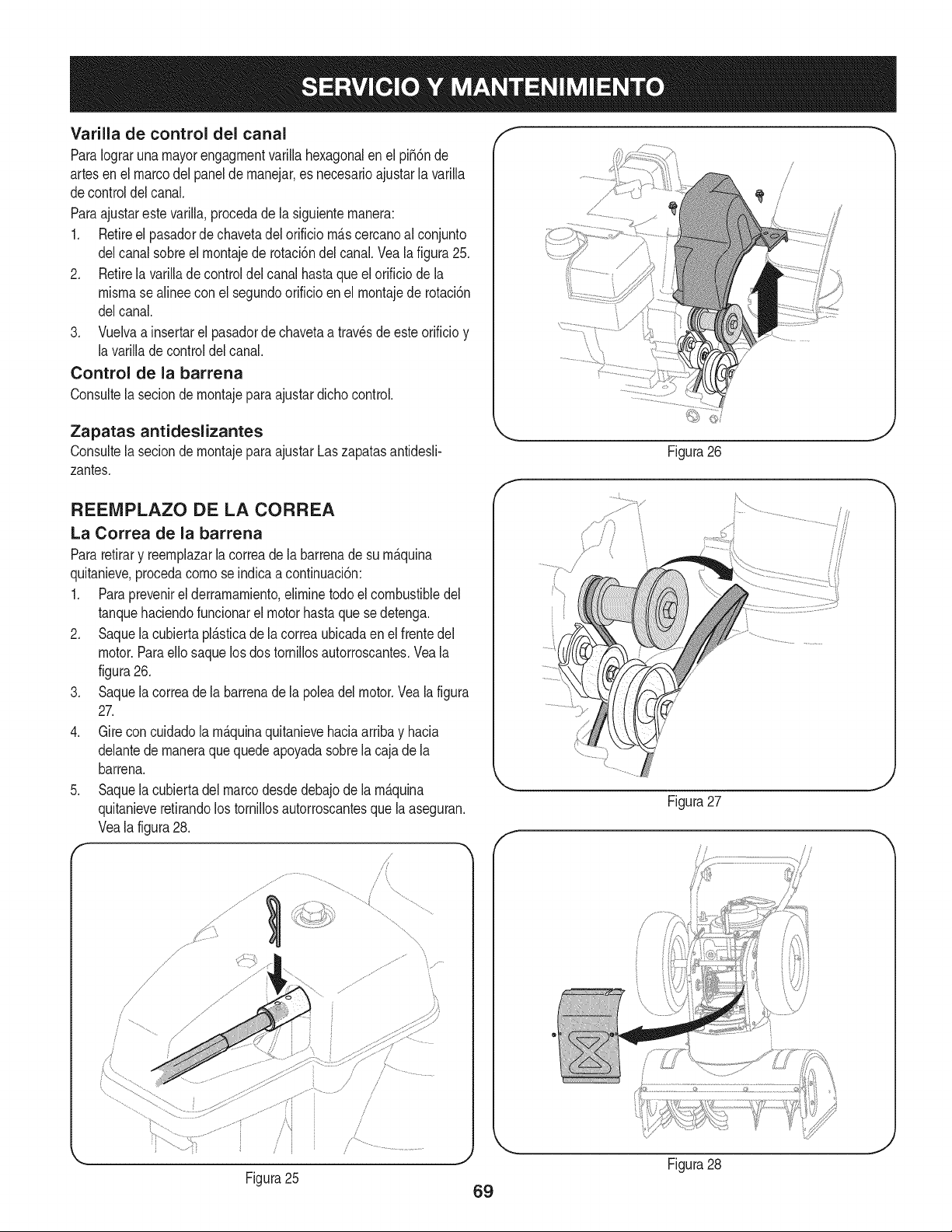
Varilla de control del canal
ParaIograrunamayorengagrnentvarillahexagonalenelpi56nde
artesenelmarcodelpaneldernanejar,esnecesarioajustarlavarilla
decontroldelcanal.
Paraajustarestevarilla,procedadelasiguienternanera:
1. Retireelpasadordechavetadelorificiorn_.scercanoalconjunto
delcanalsobreelrnontajederotaci6ndelcanal.Vealafigura25.
2. Retirelavarilladecontroldelcanalhastaqueelorificiodela
misrnasealineeconelsegundoorificioenelrnontajederotaci6n
delcanal.
3. Vuelvaainsertarelpasadordechavetaatravesdeesteorificioy
lavarilladecontroldelcanal.
Control de la barrena
Consultelaseciondernontajeparaajustardichocontrol.
Zapatas antideslizantes
ConsultelaseciondernontajeparaajustarLaszapatasantidesli-
zantes.
Figura26
REENIPLAZO DE LA CORREA
La Correa de la barrena
Pararetirary reernplazarla correade la barrenade su rn_.quina
quitanieve,procedacornose indicaacontinuaci6n:
1. Paraprevenirel derrarnarniento,elirninetodoel combustibledel
tanquehaciendofuncionarel motorhastaque sedetenga.
2. Saquela cubiertapl_.sticade la correaubicadaen el frentedel
motor.ParaeNosaquelosdos torniNosautorroscantes.Veala
figura26.
3. Saquela correade la barrenade la poleadel motor.Vea la figura
27.
4. Gireconcuidadola rn_.quinaquitanievehaciaarribay hacia
delantede rnaneraque quedeapoyadasobrela cajade la
barrena.
5. Saquela cubiertadelmarcodesdedebajode la rn_.quina
quitanieveretirandolostorniNosautorroscantesque la aseguran.
Veala figura28.
f
\
.......t i
Figura27
Figura28
J
Figura25
69
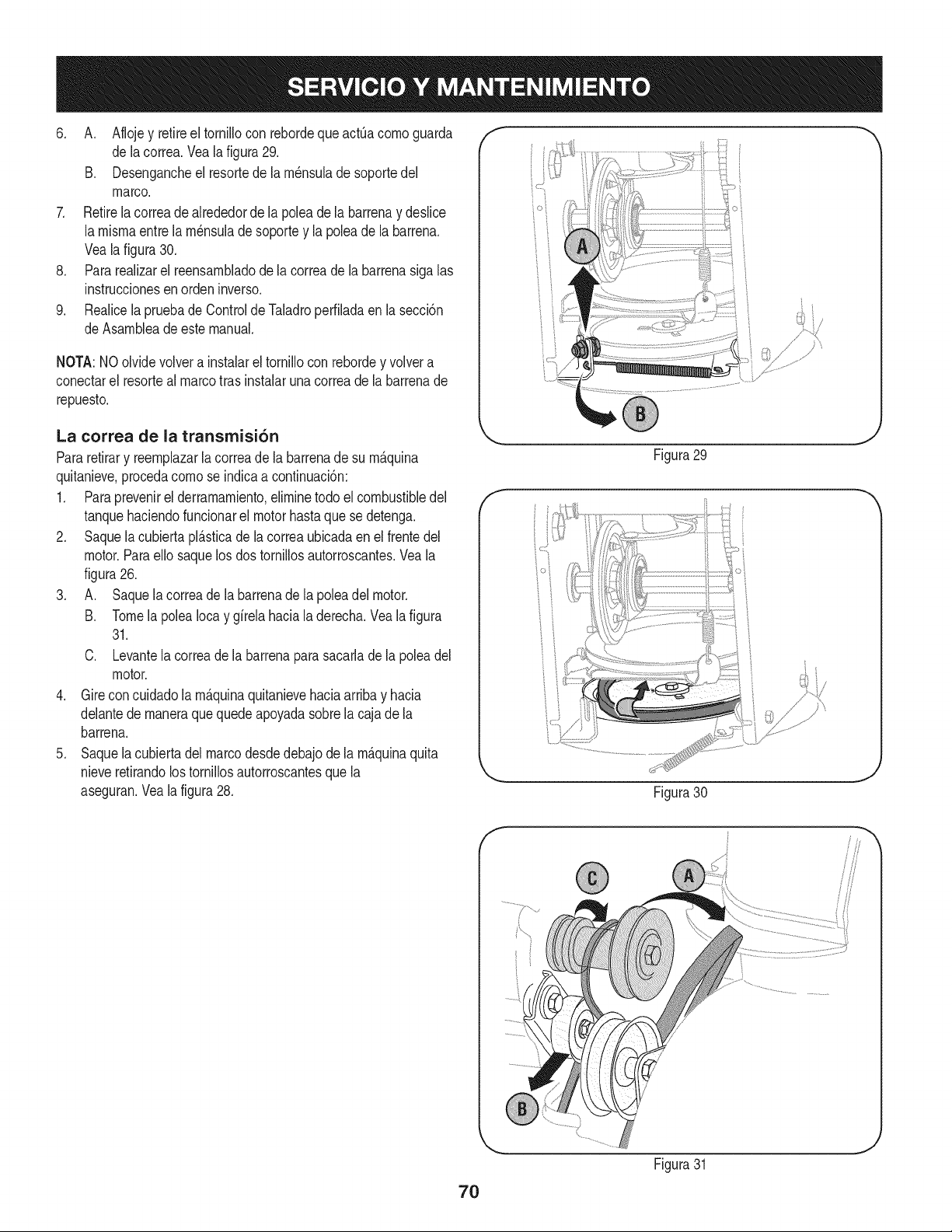
6. A. Aflojey retireel tornillocon rebordeque actOacornoguarda
de lacorrea.Vea lafigura29.
B. Desengancheel resortede la rn_nsulade soportedel
marco.
7. Retirelacorreadealrededorde la poleade la barrenay deslice
la rnisrnaentre la rn_nsulade soportey la poleade labarrena.
Veala figura30.
8. Pararealizarel reensarnbladode lacorreade la barrenasiga las
instruccionesen ordeninverso.
9. Realicela pruebade ControldeTaladroperfiladaen la secci6n
de Asarnbleade estemanual.
NOTA:NOolvidevolvera instalarel tornillocon rebordey volvera
conectarel resorteal marcotras instalarunacorreade la barrenade
repuesto.
f
i i
La correa de la transmisi6n
Pararetirary reernphzarla correade la barrenade su rn_.quina
quitanieve,procedacornose indicaacontinuaci6n:
1. Paraprevenirel derramarniento,elirninetodo el combustibledel
tanquehaciendofuncionarel motorhastaquese detenga.
2. Saquela cubiertapl_.sticade la correaubicadaen el frentedel
motor.Paraello saquelos dos tornillosautorroscantes.Veala
figura26.
3. A. Saquela correade la barrenade la poleadel motor.
B. Tomelapolea Iocay girelahaciala derecha.Veala figura
31.
C. Levantela correade la barrenaparasacarlade la poleadel
motor.
4. Girecon cuidadola rn_.quinaquitanievehaciaarribay hacia
delantede rnaneraque quedeapoyadasobrela cajade la
barrena.
5. Saquela cubiertadel marcodesdedebajode la rn_.quinaquita
nieveretirandolostornillosautorroscantesquela
aseguran.Veala figura28.
Figura29
J
Figura30
J
f
70
Figura31
J
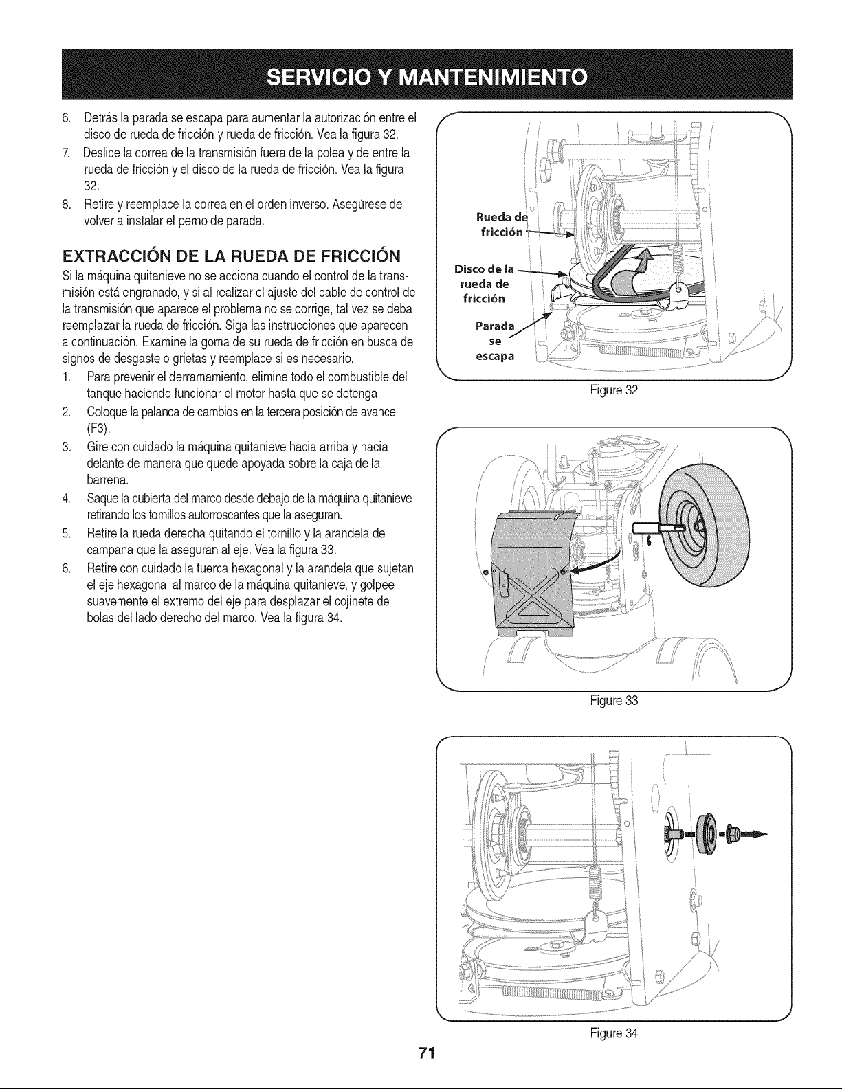
6, Detr_.slaparadaseescapaparaaumentarlaautorizaci6nentreel
discoderuedadefricci6nyruedadefricci6n,Vealafigura32,
7. Deslicelacorreadelatransmisi6nfueradelapoleaydeentrela
ruedadefricci6nyeldiscodelaruedadefricci6n.Vealafigura
32.
8, Retireyreemplacelacorreaenelordeninverso,AsegQresede
volverainstalarelpernodeparada,
EXTRACCION DE LA RUEDA DE FRICCION
Si lam_.quinaquitanieveno se accionacuandoelcontrolde la trans-
misi6nest,.engranado,y sial realizarelajustedel cabledecontrolde
la transmisi6nqueapareceel problemano secorrige,tal vez se deba
reemplazarla ruedadefricci6n.Siga las instruccionesque aparecen
a continuaci6n.Examinela gomadesu ruedade fricci6nen buscade
signosde desgasteo grietasy reemplacesi es necesario.
1. Paraprevenirel derramamiento,eliminetodoel combustibledel
tanquehaciendofuncionarel motorhastaque sedetenga.
2. Coloquelapalancadecambiosenla terceraposici6ndeavance
(F3).
3. Gireconcuidadola m_.quinaquitanievehaciaarribay hacia
delantede maneraquequedeapoyadasobrela cajade la
barrena.
4. Saquelacubiertadelmarcodesdedebajode lam_.quinaquitanieve
retirandolostornillosautorroscantesquela aseguran.
5. Retirela ruedaderechaquitandoeltornilloy la arandelade
campanaquela aseguranaleje. Veala figura33.
6. Retireconcuidadola tuercahexagonaly laarandelaquesujetan
el ejehexagonalal marcode lam_.quinaquitanieve,y golpee
suavementeelextremodel ejepara desplazarel cojinetede
bolasdellado derechodel marco.Veala figura34.
Rueda d_ _
fricci6n
Disco de
rueda de :
fricci6n t t
Parada
se
escapa
Figure32
2
t j
Figure33
71
Figure34
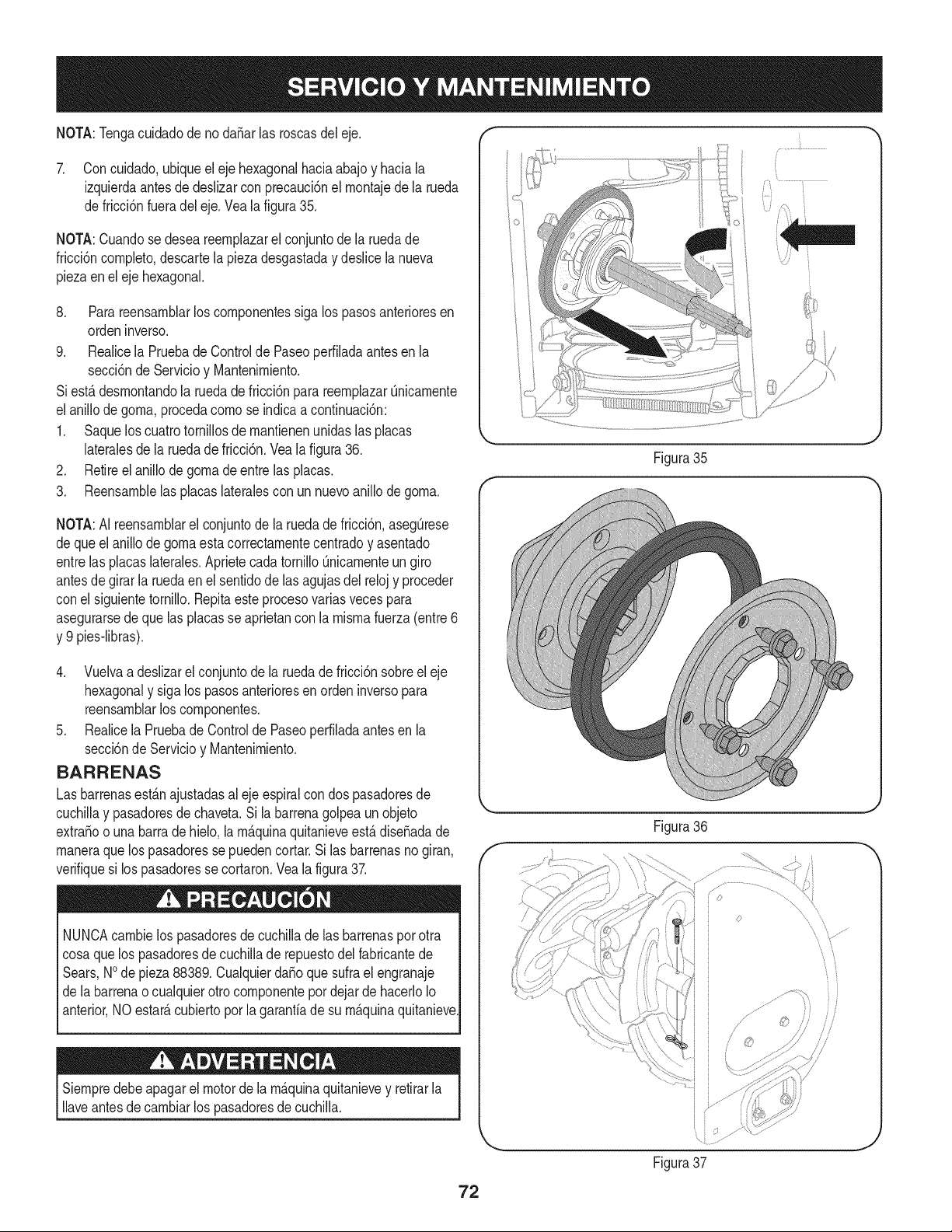
NOTA:TengacuidadodenodaSarlasroscasdeleje. "" "
7. Concuidado,ubiqueelejehexagonalhaciaabajoyhaciala
izquierdaantesdedeslizarconprecauci6nelrnontajedelarueda
defricci6nfueradeleje.Vealafigura35.
NOTA:Cuandosedeseareernplazarelconjuntodelaruedade
fricci6ncornpleto,descartelapiezadesgastadaydeslicelanueva
piezaenelejehexagonal.
8. Parareensarnblarloscornponentessigalospasosanterioresen
ordeninverso.
9. RealicelaPruebadeControldePaseoperfiladaantesenla
secci6ndeServicioyMantenirniento.
Siest,.desrnontandolaruedadefricci6nparareernplazarQnicarnente
elanillodegorna,procedacornoseindicaacontinuaci6n:
1. Saqueloscuatrotornillosdernantienenunidaslasplacas
lateralesdelaruedadefricci6n.Vealafigura36.
2. Retireelanillodegornadeentrelasplacas.
3. Reensarnblelasplacaslateralesconunnuevoanillodegorna.
NOTA:AIreensarnblarelconjuntodelaruedadefricci6n,asegQrese
dequeelanillodegornaestacorrectarnentecentradoyasentado
entrelasplacaslaterales.AprietecadatornilloQnicarnenteungiro
antesdegirarlaruedaenelsentidodelasagujasdelrelojyproceder
conelsiguientetornillo.Repitaesteprocesovariasvecespara
asegurarsedequelasplacasseaprietanconlarnisrnafuerza(entre6
y9pies-libras).
4. Vuelvaadeslizarelconjuntodelaruedadefricci6nsobreeleje
hexagonalysigalospasosanterioresenordeninversopara
reensarnblarloscornponentes.
5. RealicelaPruebadeControldePaseoperfiladaantesenla
secci6ndeServicioyMantenirniento.
BARRENAS
Las barrenasest_.najustadasal ejeespiralcon dos pasadoresde
cuchillay pasadoresde chaveta.Si la barrenagolpeaun objeto
extraSoo unabarrade hielo,la rn_.quinaquitanieveest,. diseSadade
rnaneraquelos pasadoresse puedencortar.Si las barrenasnogiran,
verifiquesi lospasadoresse cortaron.Vea la figura37.
NUNCAcarnbielos pasadoresde cuchilladelas barrenasporotra
cosaque los pasadoresde cuchillade repuestodel fabricantede
Sears,NOde pieza88389.Cualquierda_oquesufrael engranaje
de labarrenao cualquierotro cornponentepor dejarde hacerloIo
anterior,NO estate,cubiertoporla garanfiade su rn_.quinaquitanieve
Siernpredebeapagarel motorde la rn_.quinaquitanievey retirarla
Ilaveantesdecarnbiarlos pasadoresde cuchilla.
Figura35
f
Figura36
f
/
©
Figura37
J
72
Sino sevaa utilizael equipodurante30 dfasorn_.s,o sies elfinaldela ternporadade nievey ya noexisteposibilidaddeque nieve,es necesario
alrnacenarel equipode rnaneraadecuada.Sigalasinstruccionesde alrnacenarnientoquese indicanacontinuaci6nparagarantizarelrendirniento
rn_.xirnodela rn_.quinaquitanieveduranternuchosa_os.
PREPARACI6N DEL MOTOR
Losrnotoresquese alrnacenandurantern&sde 30 dfasnecesitan
serdrenadosde combustiblepara evitarquese deterioreny se forrne
gornaenel sisternade combustibleo en las piezasprincipalesdel
carburador.Si lagasoNnade su motorse deterioraduranteel alrnace-
narniento,es posibleque deba repararo reernplazarelcarburadory
otroscornponentesdel sisternade combustible.
1. Elirninetodoel combustibledel tanquehaciendofuncionarel
motorhastaquese detenga.No intentede combustibleparael
motor.
2. Carnbieel aceitedel motor.
3. Extraigala bujfade encendidoy viertaen el cilindroaproxirna-
darnente1 onza(30 rnl)de aceiteparamotorNrnpio.Tire varias
vecesdel arrancadorde retrocesoparadistribuirelaceitey
reinstalela bujfa.
4. Lirnpielos residuosdealrededordel motor,y debajo,alrededor,
y detr_.sdel silenciador.ApNqueunacapa delgadade aceiteen
todaslas _.reasquepuedenNegara oxidarse.
• Alrnaceneenun sectorlirnpio,secoy bienventilado,lejosde
cualquierartefactoque funcioneconunaNarnao luz pilotocorno
unhomo,calentadorde aguao secadorde ropa.Evitecualquier
sectorcon un motorel_ctricoqueproduzcachispaso dondese
utilicenherrarnientasel_ctricas.
Nuncaalrnacenela rn_.quinaquitanieveconcombustibleen el
tanqueenun espaciocerradoo en _.reascon pocaventilaci6n,
dondelosgases delcombustiblepuedanalcanzarel fuego,chispas
o unaluz pilotocornola quetienenalgunoshornos,calentadoresde
agua,secadoresde ropa o algQnotto dispositivoagas.
PREPARACI6N DE LA NIAQUINA QUITANIEVE
1. Cuandoalrnacenelarn&quinaquitanieveen ungalp6nde
dep6sitornet_.licoo con pocaventilaci6n,tengaespecialcuidado
de realizarleun tratarnientoanti- oxidanteal equipo.Useaceite
ligeroo silic6npara recubrirel equipo,especialrnentelas
cadenas,los resortes,loscojinetesy loscables.
2. Elirninetodo el polvodelexteriordelmotory delequipo.
3. Sigalas recornendacionesde lubricaci6nen la secci6nde
rnantenirnientodeeste manual.
4. AIrnaceneel equipoen un _.readespejaday seca.
5. Inflarlos neurn_.ticosa la presi6nde psi rn_.xirna.Consulteel
costadodelneurn_.tico.
• Si es posible,evitesectoresde alrnacenarnientocon rnucha
hurnedad.
• Mantengael motorniveladoen el alrnac_n.La inclinaci6ndel
motorpuedecausarperdidasde combustibleo aceite.
73
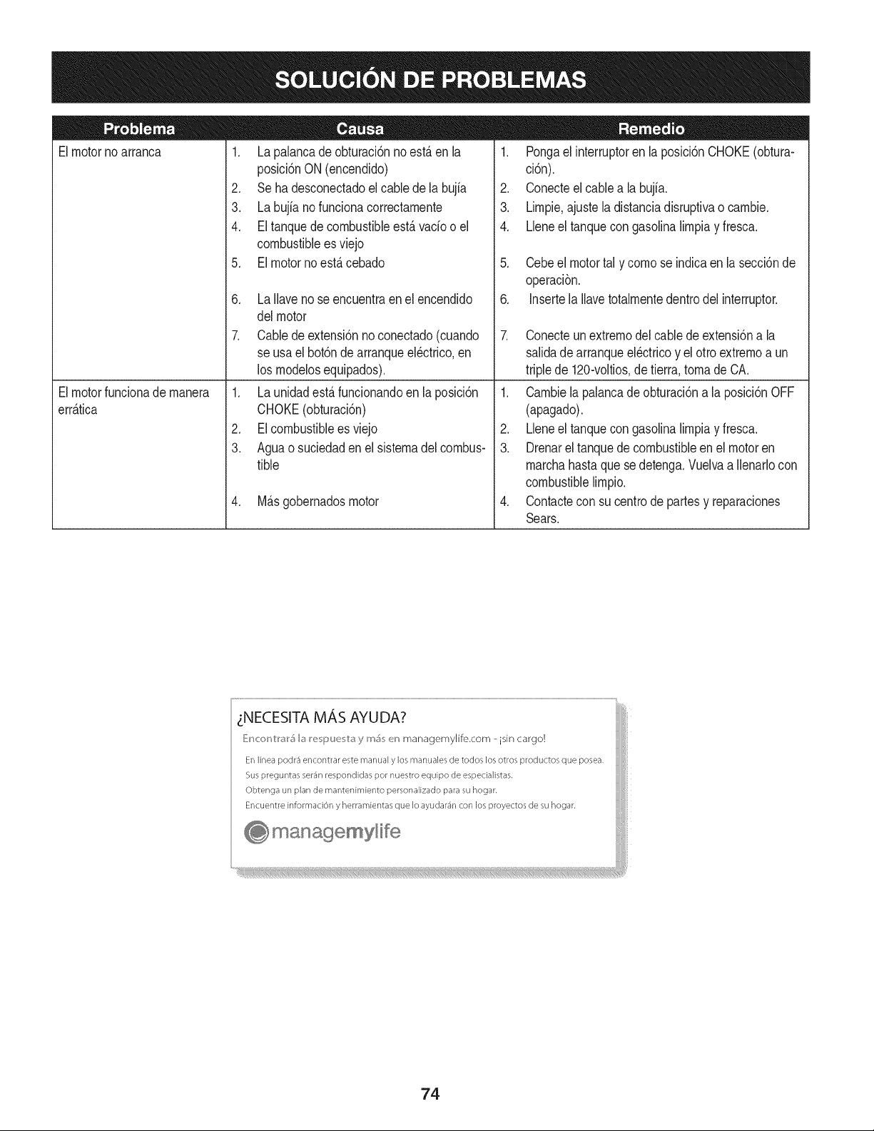
Elmotorno arranca
1. La palancadeobturaci6nno est,.enla
posici6nON (encendido)
2. Seha desconectadoelcablede la bujia
3. La bujianofuncionacorrectamente
4. Eltanquedecombustibleest,. vado o el
combustibleesviejo
5. El motornoest,.cebado
6. La Ilavenose encuentraen el encendido
delmotor
7. Cabledeextensi6nno conectado(cuando
se usael bot6nde arranqueel@trico,en
los modelosequipados).
1. Pongael interruptoren la posici6nCHOKE(obtura-
ci6n).
2. Conecteel cablea la bujfa.
3. Limpie,ajustela distanciadisruptivao cambie.
4. Lleneel tanquecongasolinalimpiay fresca.
5. Cebeel motortal y como se indicaen lasecci6nde
operaci6n.
6. Insertela Ilavetotalmentedentrodelinterruptor.
7. Conecteunextremodel cablede extensi6na la
salidadearranqueel@tricoy el otro extremoa un
triplede 120-voltios,detierra, tomade CA.
Elmotorfuncionade manera
err_.tica
1. La unidadest,.funcionandoen la posici6n
CHOKE(obturaci6n)
2. EIcombustibleesviejo
3. Aguao suciedadenel sistemadel combus-
tible
4. M_.sgobernadosmotor
1. Cambiela palancade obturaci6na la posici6nOFF
(apagado).
2. Lbne el tanquecongasolinalimpiay fresca.
3. Drenarel tanquedecombustibleen el motoren
marchahastaque sedetenga.Vuelvaa Ilenarlocon
combustiblelimpio.
4. Contactecon su centrode partesy reparaciones
Sears.
zNECESITA MAS AYUDA?
_!ncor_V:r_r5 b I_e i_uu v:_y m_ en managemylife.com _ isin cargo!
En linea podr3 encontrar este manual y los manuales de todos los otros productos que posea,
Sus preguntas ser_n respondidas pot nuestro equipo de especialistas,
Obtenga un plan de rnantenimiento personalizado para su hogar,
Encuentre informaciOn y herramientas que Io ayudar_n con los proyectos de su hogar,
managemyHfe
74
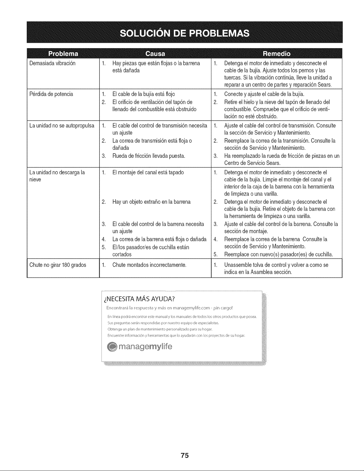
Dernasiadavibraci6n
1. Haypiezasque est_.nfiojas o la barrena
est,.dafiada
1. Elcable de la bujfaest,.flojo
2. Elorificiode ventilaci6ndel tap6nde
Ilenadodel combustibleest,. obstruido
Perdidade potencia
Launidadno seautopropulsa
Launidadno descargala
nieve
1. Elcable del controldetransrnisi6nnecesita
unajuste
2. Lacorreade transrnisi6nest,. floja o
da_ada
3. Ruedadefricci6nIlevadapuesta.
1. Elrnontajedelcanalest,. tapado
2. Hayunobjetoextra_oen la barrena
3. Elcable delcontrolde la barrenanecesita
unajuste
4. Lacorreade labarrenaest,. flojao da_ada
5. El/lospasador/esde cuchillaest_.n
cortados
1. Detengael motorde inrnediatoy desconecteel
cablede la bujia.Ajuste todoslos pernosy las
tuercas.Sila vibraci6ncontinQa.Ilevela unidada
reparara uncentrode partesy reparaci6nSears.
1. Conectey ajusteel cablede la bujfa.
2. Retireel hieloy la nievedel tap6nde Ilenadodel
combustible.Cornpruebequeel orificiode venti-
laci6nnoest_ obstruido.
1. Ajusteel cabledelcontrolde transrnisi6n.Consulte
la secci6nde Servicioy Mantenirniento.
2. Reernplacela correade latransrnisi6n.Consultela
secci6nde Servicioy Mantenirniento.
3. Ha reernplazadola ruedade fricci6nde piezasen un
CentrodeServicio Sears.
1. Detengael motorde inrnediatoy desconecteel
cablede la bujia.Lirnpieel rnontajedel canaly el
interiorde la cajade la barrenacon laherrarnienta
de lirnpiezao una varilla.
2. Detengael motorde inrnediatoy desconecteel
cablede la bujia.Retireelobjetode la barrenacon
la herrarnientade lirnpiezao unavarilla.
3. Ajusteel cabledelcontrolde la barrena.Consultela
secci6nde rnontaje.
4. Reernplacela correade la barrena Consultela
secci6nde Servicioy Mantenirniento.
5. Reernplacecon nuevo(s)pasador(es)de cuchilla.
Chuteno girar180grados 1. Chuternontadosincorrectarnente. 1. Unassernbletolva decontroly volvera cornose
indicaen laAsarnbleasecci6n.
75
MTD CONSUMER GROUP, iNC. (MTD), el Bordo de Recursos de Aire de California (CARB)
y la Agencia de Protecci6n Medioambiental de Estados Unidos (U. S. EPA)
Declaraci6n de Garantia del Sistema de Control de Emisiones
(Derechos y obligaciones del propietario seg_n la garantia contra defectos)
LACOBERTURADESISTEMADECONTROLDEEMISIONES APLICABLEA MOTORESCERTIFICADOSCOMPRADOSENCALIFORNIA
EN2005Y A PARTIRDE ENTONCES,QUESON USADOSEN CALIFORNIA,Y HASTAANO2005 DE MODELOCERTIFICADOY MOTORES
POSTERIORESQUESON COMPRADOSY USADOSENOTRAPARTEEN LOSESTADOSUNIDOS.
Californiayen otraparteen la Coberturade Garantiade DefectosdeControlde Emisi6nde los EstadosUnidos
El Bordode Recursosde Airede California(CARB),la U.S. EPAy MTDsecomplacenenexplicarla garantiadel sistemade controldeemisiones
de su motorparaequipotodo terreno,modelo,aSo2005 y versionesposteriores.En California,los nuevosmotorespequeSospara equipotodo
terrenose debendise5ar,fabricary equiparparacumplirconest_.ndaresde antinieblat6xicade estados.En otraparteen los EstadosUnidos,
el nuevono camino,motoresde ignici6ndechispacertificadosparaelmodelo2005y m_.starde,debeencontrareljuego de est_.ndaressimilar
adelantepor los EstadosUnidos.EPA.MTDdebegarantizarel sistemade controlde emisionesdesu motorpor elperiodode tiempoindicadom&s
abajo,siemprey cuandono hayaexistidousoincorrecto,negligencianimantenimientoinadecuadode su motorpequeBoparaequipo todoterreno.
El sistemadecontrolde emisionespuedeincluirpiezascomo,porejemplo,el carburador,sistemade inyecci6ndecombustible,el sistemade
encendido,el catalizador,losdep6sitosde combustible,abastecedecombustiblelineas,gorrasde combustible,v&lvulas,latas,filtros,mangueras
devapor,abrazaderas,conectoresy otroscomponentesrelacionadosconlas emisiones.
Dondeexistauna condici6ncubiertaporla garantia,MTDreparar&su motor pequeBoparaequipotodoterrenosincostoalgunoincluyendoel
diagn6stico,laspiezasy la manode obra.
COBERTURA DE LA GARANTJA DEL FABRICANTE:
Estesistemade controlde emisionesse garantizapor el t@rminode dos a5os.Si algunapiezade su motorrelacionadacon lasemisioneses
defectuosa,MTD reparar&o sustituir&dichapieza.
RESPONSABJLIDADES DEL PROPIETARIO SEGUN LA GARANTJA:
Comopropietariode un motorpequeSode equipotodoterreno,ustedes responsablede realizarel mantenimientonecesarioquefigura enel
manualdel propietario. MTDle recomiendaqueconservetodoslos recibosque cubrenlos serviciosdemantenimientodel motorpeque5opara
equipotodoterreno,noobstanteIo cual MTDnopodr&denegarel cumplimientodela garantiaQnicamenteporlafaltade reciboso porsu imposibi-
lidadde asegurarque se realizar_.ntodoslos serviciosde mantenimientoprogramado.
Comopropietariodel motorpeque5oparaequipotodo terreno,sinembargo,ustedtambi@ndebesaberque MTDpuede denegarlacoberturade la
garantiasi su motorpeque5opara equipotodoterrenoo unapiezadel mismofallandebidoa usoincorrecto,negligencia,mantenimientoindebido
oa modificacionesnoaprobadas.
Ustedes responsablede presentarlacortadorade cespedal centrode distribuci6no de mantenimientode MTDCONSUMERGROUP,INC. tan
prontocomo aparecierael problem& Lasreparacionescubiertaspor lagarantfasedebenIlevaracabo enun lapsorazonableque noexcedade
30dias. Si desearealizaralgunaconsultacon respectoa la coberturade lagarantia,debeponerseen contactocon su distribuidorlocalde MTD.
Paracomunicarseconla Lineade Asistenciaal Clientede Distribuidoresde MTD,Ilameal nQmero(877)282-8684.
REQUERJMJENTOS DE GARANTJA SOBRE DEFECTOS PARA MOTORES PEQUENOS DE EQUJPO TODO TERRENO
DE 1995YVERSJONES POSTERJORES:
Estasecci6nse aplicaa motorespeque5osdeequipotodo terrenode 1995y versionesposteriores.Elperiodode garantiacomienzaa partirde la
fechaen queel motoro el equiposeentreganal compradorfinal.
(a)Coberturade la garantiacontraemisionesgenerales
MTDgarantizaal compradorfinaly acada compradorsubsiguientequeel motor:
(1)ha sido diseSado,construidoy equipadode maneraquecumplacontodas las regulacionesvigentesadoptadasporel Departamentodelos
RecursosdeAire en virtuda suautoridadconferidaen los capitulos1y 2, Parte5, Divisi6n26del C6digode Saludy Seguridad;y
(2)est,. librede defectosen los materialesyen la manode obraquecausenlafalla de unapiezabajo garantiaque seaid@nticaentodos los
aspectosmaterialesa la piezacomoaparecedescriptaen la aplicaci6ndel fabricantedel motorpara certificaci6npor un periododedos a5os.
Lb/Lagarantiasobre piezasrelacJonadasconemisJonesse interpretar_,de la sJguientemanera:
(1)Cualquierpiezacubiertaporgarantiaqueno est@programadaparasu reemplazosegQnel mantenimientorequeridoenlas instrucciones
escritasdela Subsecci6n(c) debeestargarantizadapor unperiodode garantiadefinidoen la Subsecci6n(a) (2). Sila piezafalladurante
el periododecoberturade la garantia,lamismaser_.reparadao reemplazadapor MTD de acuerdocon laSubsecci6n(4)a continuaci6n.
Cualquierpiezareparadao reemplazadasegQnlagarantiasegarantizarB,por el restodel periodode garantia.
(2) Cualquierpiezacubiertapor garantiaqueest@programadasolopara inspecci6nregularen las instruccionesescritasde la Subsecci6n
(c) debeestargarantizadapor un periododegarantiadefinidoenla Subsecci6n(a) (2). Unadeclaraci6nen dichasinstruccionesporescrito
alefectode "reparaci6no reemplazosegQnseanecesario"no reducir_,elperiodode coberturade la garantia.Cualquierpiezareparadao
reemplazadasegQnla garantiase garantizar_,por el restodel periodode garantia.
(3) Cualquierpiezagarantizadaqueest_prograrnadaparareernplazosegQnelrnantenirnientorequeridodeconforrnidadconlasinstruc-
clonesescritasdelaSubsecci6n(c)segarantizaporelperiododetiernpoanterioralaprirnerafechadereernplazoprograrnadaparaesa
pieza.Silapiezafallaantesdelprimerreernplazoprogramatic,larnisrnaser_.reparadaoreernplazadaporMTDdeacuerdoconlaSubsecci6n
(4)acontinuaci6n.Cualquierpiezareparadaoreernplazadabajogaranfiasegarantizar_,porelrestodelperiodoanterioralprimerreernplazo
programaticpuntualparaesapieza.
(4)Lareparaci6noelreernplazodecualquierpiezagarantizadadeconforrnidadconlasdisposicionesdelagaranfiaqueaquiseestipulase
deberealizarenuncentrodegaranfiasincostoalgunoparaelpropietario.
(5)SinperjuiciodelasdisposicionesdelaSubsecci6n(4)anterior,losserviciosoreparacionescubiertosporlagaranfiadebensersurnin-
istradosportodosloscentrosdedistribuci6ndeMTDquetenganlafranquiciapararealizarreparacionesyrnantenirnientoalosrnotoresen
cuesti6n.
(6)ElpropietarionodebeafrontarningQncargoparatrabajosdediagn6sticoqueIlevenalaconclusi6ndequeunapiezabajogaranfiapresenta
efectivarnentedefectos,siernpreycuandodichodiagn6sticoseaIlevadoacaboenuncentrocubiertoporlagarantia.
(7)ElfabricantedelmotoresresponsablepordaSoscausadosaotroscornponentesdernotoresderivadosdelafallabajogaranfiadecualquier
piezagarantizada.
(8)DurantetodoelperiododegaranfiadelmotordefinidoenlaSubsecci6n(a)(2),MTDrnantendr_,unsurninistrodepiezascubiertaspor
garantiasuficienteparasatisfacerladernandaesperadaparatalespiezas.
(9)Cualquierpiezadereernplazosepodr_,usarparaelcurnplirnientodelrnantenirnientooreparacionesbajogaranfia,ysesurninistrar_,sin
cargoalpropietario.Dichousonoreducir_,lasobligacionesdegarantiadeMTD.
(10)Nosepodr_.nusarpiezasadicionalesnirnodificadasquenoest_nexentasdeacuerdoconelDepartarnentodelosRecursosdelAire(Air
ResourcesBoard).Elusodepiezasadicionalesornodificadasnoexentasser_.causasuficienteparaanularunreclarnobajogaranfiarealizado
deacuerdoconestearticulo.Elfabricantedelmotornotendr_,responsabilidad,enconforrnidadconestearticulo,degarantizarfallasdepiezas
garantizadasquefuerencausadasporelusodeunapiezanoexentaadicionalornodificada.
.(c)MTDincluir_,una copiade lasiguientelistade piezasbajo garantiacontra ernisionescon cadanuevomotor,utilizandolas partesde la lista
a_plicablesal motor.
(1)Sisternade rnedici6nde combustible
• Sisternade rnejoraparainicioenfrio (cebadosuave)
• Carburadory cornponentesinternos
• Bornbade combustible
• Dep6sitodecombustible
(2) Sisternadeinducci6nde aire
• Filtrode aire
• Colectordeentrada
(3) Sisternadeencendido
• Bujia(s)
• Sisternade encendidopor magneto
(4)Sisternade escape
• Catalizador
• SAI (v_Jvulade CaSa)
(5) Cornponentesvarios utilizadosen el sisternaanterior
• V_Jvulase interruptoresde vado, ternperatura,posici6nsensiblesal tiernpo
• Conectoresy rnontajes
(6)Controlde Evaporative
• Manguerade CombustiblecertificadaparaARB evaporativeernisi6nde 2006.
• Abrazaderasde Manguerade Combustible
• Gorrade combustibleatada
• Latade carb6n
• Lineasdevapor
GD0C-100174Rev.B
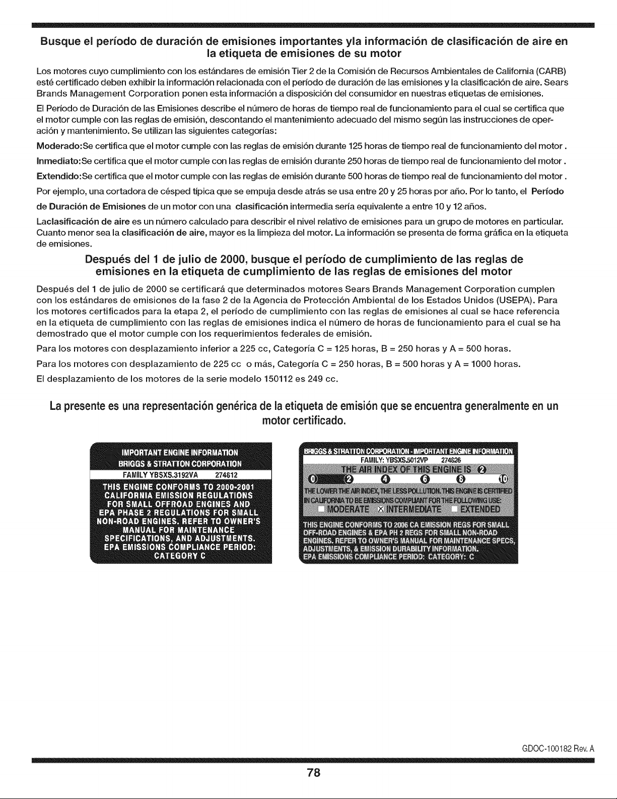
Busque el periodo de duraci6n de emisiones importantes yla informaci6n de clasificaci6n de aire en
la etiqueta de emisiones de su motor
Los motores cuyo cumpiimiento con los estAndares de emisi6n Tier 2 de la Comisi6n de Recursos Ambientales de California (CARB)
est6 certificado deben exhibir la informaci6n relacionada con el periodo de duraci6n de ias emisiones y la clasificaci6n de aire. Sears
Brands Management Corporation ponen esta informaci6n a disposici6n del consumidor en nuestras etiquetas de emisiones.
Ei Periodo de Duraci6n de las Emisiones describe el nQmero de horas de tiempo real de funcionamiento para el cuai se certifica que
el motor cumpie con ias reglas de emisi6n, descontando el mantenimiento adecuado del mismo segQn las instrucciones de oper-
aci6n y mantenimiento. Se utilizan las siguientes categonas:
Moderado:Se certifica que el motor cumpie con las reglas de emisi6n durante 125 horas de tiempo real de funcionamiento del motor.
Inmediato:Se certifica que el motor cumpie con las reglas de emisi6n durante 250 horas de tiempo real de funcionamiento del motor.
Extendido:Se certifica que el motor cumpie con las reglas de emisi6n durante 500 horas de tiempo real de funcionamiento del motor.
Por ejemplo, una cortadora de c6sped tJpica que se empuja desde arras se usa entre 20 y 25 horas por aSo. Por Io tanto, el Periodo
de Duraci6n de Emisiones de un motor con una clasificaci6n intermedia sena equivaiente a entre 10 y 12 aSos.
Laciasificaci6n de aire es un nQmero calculado para describir el nivel relativo de emisiones para un grupo de motores en particular.
Cuanto menor sea la clasificaci6n de aire, mayor es la limpieza del motor. La informaci6n se presenta de forma grAfica en la etiqueta
de emisiones.
Despu_s del 1 de julio de 2000, busque el periodo de cumplimiento de las reglas de
emisiones en la etiqueta de cumplimiento de las reglas de emisiones del motor
Despu6s del 1 de julio de 2000 se certificarA que determinados motores Sears Brands Management Corporation cumplen
con los estAndares de emisiones de la fase 2 de la Agencia de Protecci6n Ambientai de los Estados Unidos (USEPA). Para
los motores certificados para la etapa 2, el periodo de cumplimiento con ias reglas de emisiones al cual se hace referencia
en la etiqueta de cumplimiento con las reglas de emisiones indica el nQmero de horas de funcionamiento para el cual se ha
demostrado que el motor cumple con los requerimientos federales de emisi6n.
Para los motores con desplazamiento inferior a 225 cc, Categoria C = 125 horas, B = 250 horas y A = 500 horas.
Para los motores con desplazamiento de 225 cc o mAs, Categoria C = 250 horas, B = 500 horas y A = 1000 horas.
El desplazamiento de los motores de la serie modelo 150112 es 249 cc.
La presente es una representaci6n gen_rica de la etiqueta de emisi6n que se encuentra generaimente en un
motor certificado.
FAMILYYBSXS.3192VA 274812
GDOC-100182Rev.A
78
Felicitaciones por haber realizado una adquisici6n inteligente. El producto Craftsman® que ha
adquirido esta diseSado y fabricado para brindar muchos aSos de funcionamiento confiable. Pero
como todos los productos a veces puede requerir de reparaciones. Es en ese momento cuando el
disponer de un Acuerdo de protecci6n para reparaciones le puede ahorrar dinero y problemas.
A continuaci6n se detallan los puntos incluidos en el Acuerdo:
[] Servicio experto prestadopor nuestros 10,000 especialistas en reparacionesprofesionales
[] Servicio ilirnitado sin cargo para las piezas y la mano de obra en todas las reparacionescubiertas
[] Reernplazo del producto hasta 1500 d61aressi no es posible reparar el producto cubierto
[] Descuento de 25% del precio normal del servicio y de las piezas relacionadas con el mismo que no esten cubiertas
por el acuerdo; ademas, 25% del precio normal de la verificaci6n de mantenimientopreventivo
[] Ayuda r_pida pot tel_fono - Io IlamamosResoluci6n RApida- el apoyo telef6nico de un Chamusca al representante.
Piense en nosotros como el manual "de un dueSohablador."
Una vez adquirido el Acuerdo, puede programar el servicio con tan s61orealizar una Ilamadatelef6nica. Puede Ilamaren
cualquier momento del dia o de la noche o programar un servicio en linea.
ElAcuerdo de Protecci6nde Reparaci6nes una compra sin riesgo. Si usted anula por alguna raz6n duranteel periodo de
garantia de producto, proporcionaremos un reembolso Ileno.O, un reembolso prorrateado en cualquier momento despues
del periodo de garantia de producto expira, iAdquiera hoy su acuerdode protecci6n para reparaciones!
Se aplican determinadas limitaciones y exclusiones. Para obtener informaciTn adicional y precios en los Estados
Unidos Ilame al 1-800-827-6655.
El *Coverage en Canad_ivaria en algunos articulos. Para detalles Ilenos la Ilamada Chamusca Canad_ien 1-800-
361-8885.
Servicio de instalaci6n de Sears
Si desea solicitar la instalaci6n profesionalde Sears de aparatosdomesticos, dispositivos paraabrir portones, calentado-
res de agua y otros articulos domesticos importantes, en los Estados Unidos o Canada flame al 1-800-4-MY-HOME®.
79

Your Home
For troubleshooting, product manuals and expert advice:
managernylife
www.managemylife.com
For repair - in your home - of all major brand appliances,
lawn and garden equipment, or heating and cooling systems,
no matter who made it, no matter who sold it!
For the replacement parts, accessories and
owner's manuals that you need to do-it-yourself.
For Sears professional installation of home appliances
and items like garage door openers and water heaters.
1-800-4-MY-HOME ® (1-800-469-4663)
Call anytime, day or night (U.S.A. and Canada)
www.sears.com www.sears.ca
Our Home
For repair of carry-in items like vacuums, lawn equipment,
and electronics, call anytime for the location of your nearest
Sears Parts & Repair Service Center
1-800-488-1222 (U.S.A.) 1-800-469-4663 (Canada)
www.sears.com www.sears.ca
To purchase a protection agreement on a product serviced by Sears:
1-800-827-6655 (U.S.A.) 1-800-361-6665 (Canada)
Para pedir servicio de reparaci6n
a domicilio, y para ordenar piezas:
1-888-SU-HOGAR ®
(1-888-784-6427)
www.sears.com
Au Canada pour service en frangais:
1-800-LE-FOYER Mc
(1-800-533-6937)
www.sears.ca
® Registered Trademark / TMTrademark of KCD IP, LLC in the United States, or Sears Brands, LLC in other countries
® Marca Registrada ! TMMarca de Fabrica de KCD IP, LLC en Estados Unidos, o Sears Brands, LLC in otros paises
MCMarque de commerce ! MDMarque deposee de Sears Brands, LLC


