Loading ...
Installation Instructions
i| I IIN I II IN
Minimum Clearance Other Than Alcove or Closet Installation
Minimum clearance to combustible surfaces and for air opening are: 0 in. clearance both sides and ! in. rear. Consideration
must be Nven to provide adequate clearance for proper operation and service.
i II HU. I N . I Iml. I III I .
II I I
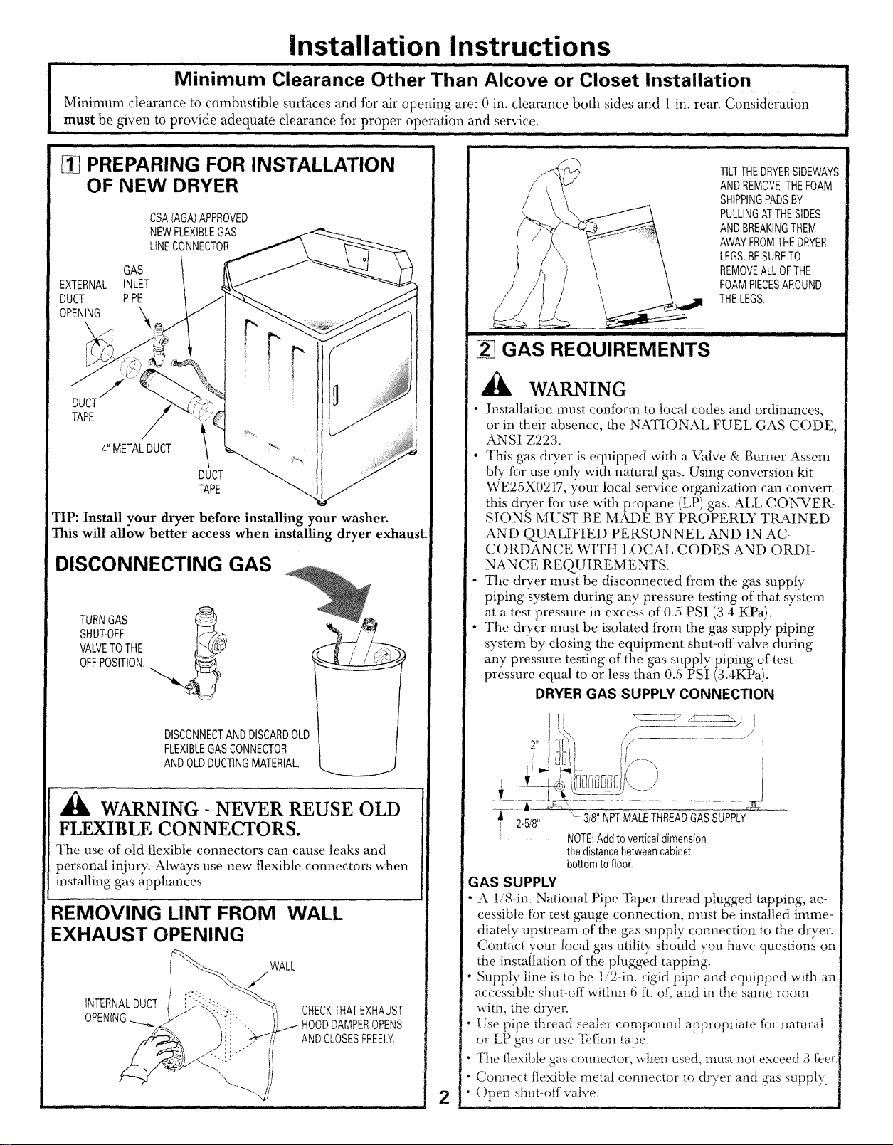
[_ PREPARING FOR INSTALLATION
OF NEW DRYER
GAS
EXTERNAL INLET
DUCT PIPE
OPENING '_
CSA(AGA)APPROVED
NEWFLEXIBLEGAS
LINECONNECTOR
TAPE
4" METALDUCT
DUCT
TAPE
TIP: Install your dryer before installing your washer.
This will allow better access when installing dryer exhaust.
DISCONNECTING GAS
TURNGAS
SHUT-OFF
VALVETOTHE
OFFPOSITION.
DISCONNECTANDDISCARDOLD
FLEXIBLEGASCONNECTOR
ANDOLDDUCTINGMATERIAL.
WARNING- NEVER REUSE OLD
FLEXIBLE CONNECTORS.
The use of old flexible connectors can cause leaks and
personal injury. Always use new flexible cormectors when
installing gas appliances.
REMOVING LINT FROM WALL
EXHAUST OPENING
WALL
CHECKTHATEXHAUST
DAMPEROPENS
ANDCLOSESFREELY,
2
/
iii
i iii ii i i
GAS REQUIREMENTS
,, i i i
TILTTHEDRYERSIDEWAYS
ANDREMOVETHEFOAM
SHIPPINGPADSBY
PULLINGATTHESIDES
ANDBREAKINGTHEM
AWAYFROMTHEDRYER
LEGS.BESURETO
REMOVEALLOFTHE
FOAMPIECESAROUND
THELEGS,
GAS SUPPLY
" A !/8-in. National Pipe Taper thread plugged tapping, ac-
cessible for test gauge connection, must be installed imme-
diately upstream of the gas supply connection to the dryer.
Contact your local gas utility should you have questions on
the instailation of the plugged tapping.
• Supply line is to be 1/24n. rigid pipe and equipped with an
accessible shut-off within 6 fL of\ and in the same room
with, the drver.
Ese pipe thlead sealer compound appropriate for natural
or LP gas or use -[bflon tape.
" The flexible gas connector, _&en used, must not exceed 3 feet.
• Connect flexible metal connector to dryer and gas supply.
• Open shut-off vane.
I 3,, ,f-- -- ./
f
t[3i/
! {li i!/---.
7__
2-5/8" -3/8" NPTMALETHREADGASSUPPLY
....... NOTE:Addtoverticaldimension
thedistancebetweencabinet
bottomtofloor.
WARNING
• Installation must conform to local codes and ordinances,
or in their absence, the NATIONAl, FUEL GAS CODE,
ANSI Z223.
• This gas dryer is equipped with a Valve & Burner Assem-
bly for use only with natural gas. Using conversion kit
WE25X0217, your local service organization can convert
this dryer for use with propane (LP) gas. ALL CONVER-
SIONS MUST BE MADE BY PROPERLY TRAINED
AND QUALIFIED PERSONNEL AND IN AC-
CORDANCE WITH LOCAL CODES AND ORDI-
NANCE REQUIREMENTS.
• The dryer must be disconnected from the gas supply
piping system during any pressure testing of that system
at a test pressure in excess of 0.5 PSI (3.4 KPa).
• The dryer nrust be isolated from the gas supply piping
system by closing the equipment shut-off valve during
any pressure testing of the gas supply piping of test
pressure equal to or less than 0.5 PSI (3.4KPa).
DRYER GAS SUPPLY CONNECTION
Loading ...
Loading ...
Loading ...