Read all safety rules and instructions carefully before operating this tool.
Owner’s Manual
TOLL-FREE HELPLINE: 1-888-90WORKS
(888.909.6757)
12 Amp Electric Snow Thrower
26032

2
Contents .............................................................................................................................. 2
Product specications .......................................................................................................... 2
Safety information .............................................................................................................3-4
Symbols ............................................................................................................................5-6
Electrical ........................................................................................................................... 7-8
Know your snow thrower ...................................................................................................... 9
Assembly ...................................................................................................................... 10-13
Operation ...................................................................................................................... 14-17
Maintenance ................................................................................................................. 18-20
Troubleshooting ................................................................................................................. 21
Warranty ............................................................................................................................ 22
Exploded View ................................................................................................................... 23
Parts List....................................................................................................................... 24-25
Notes ............................................................................................................................ 26-27
PRODUCT SPECIFICATIONS
12 AMP ELECTRIC SNOW THROWER
Motor .................................................................................................. 120 V, 60 Hz, 12 A
No-load speed ............................................................................................... 2,400 RPM
Clearing width ..........................................................................................20 in. (50.8 cm)
Clearing depth .........................................................................................10 in. (25.4 cm)
Impeller size ............................................................................................ 18 in. (45.7 cm)
Discharge distance ................................................................................Up to 20 ft. (6 m)
Wheels ......................................................................................................8 in. (20.3 cm)
Weight ..................................................................................................... 35 lbs (15.9 kg)
CONTENTS

3
SAFETY INFORMATION
FOLLOW THESE RULES WHILE OPERATING THE SNOW THROWER
I M P O R T A N T
READ AND UNDERSTAND ALL INSTRUCTIONS. Failure to follow all instructions listed below
may result in electric shock, re, and/or serious personal injury.
• Walk. Do not run.
• Verify that the Snow Thrower is not in contact with anything before turning it on.
• Stay away from the discharge opening at all times. Keep face, hands, and feet away from
concealed, moving, or rotating parts.
• Be attentive when using the Snow Thrower, and stay alert for holes in the terrain and other
hidden hazards or trafc.
• Do not use the Snow Thrower on a gravel or crushed rock surface. Use extreme caution when
crossing gravel/crushed rock drives, walks, or roads.
• Move up and down slopes when clearing snow. Do not go across a slope. Use caution when
changing direction. Do not use this Snow Thrower to clear snow from steep slopes.
• Do not attempt to use the Snow Thrower on a roof or on any steeply inclined slippery surface.
• Do not operate the Snow Thrower if the guards, plates, and other safety protective devices
are not in place.
• Do not operate the Snow Thrower near glass enclosures, automobiles, trucks, window wells,
drop-offs, etc. without properly adjusting the angle of the snow discharge. Keep children and
pets away from the work area.
• Do not force or overload the Snow Thrower. The Snow Thrower will perform better and safer
when it is used at the rate that it was designed to work at.
• Do not operate the Snow Thrower at high speeds on slippery surfaces. Look behind, and
exercise caution when backing up.
• Do not direct the discharge toward people, and do not allow anyone to move in front of the
Snow Thrower while it is in use.
• Wear safety glasses or goggles that meet ANSI Z87.1 standards, and wear ear/hearing
protection when using this Snow Thrower.
• Use the Snow Thrower in daylight or in good articial light.
• Avoid accidental start-ups. Remain in the starting position when turning the Snow Thrower
on. The operator and the Snow Thrower must be in a stable position during start-up. See the
section entitled Starting/Stopping Instructions.
• Use the proper tool. Only use this Snow Thrower for the purpose that it was designed for.
• Do not overreach. Always keep proper footing and balance.
• Hold the Snow Thrower with both hands while it is in use. Keep a rm grip on the handles or the grips.
• Keep hands, face, and feet away from all moving parts. Do not touch or try to stop the impeller
while it is rotating.
• If the impeller does not rotate freely due to frozen ice, thaw the Snow Thrower thoroughly

4
SAFETY INFORMATION
before attempting to use it.
• Keep the impeller clear of debris.
• Do not attempt to clear the impeller while the motor is running or while the Snow Thrower is plugged
in it. Turn the motor off and unplug the Snow Thrower from the extension cord or the outlet.
• Keep clothing and body parts away from the rotor.
• Do not operate the motor at a faster speed than necessary. Do not run the motor at high speed
while not clearing snow.
• Stop the motor when snow clearing is delayed or when moving from one location to another.
• Unplug the Snow Thrower when it is being transported and when it is not in use.
• After striking a foreign object, turn the Snow Thrower off and unplug it, and then inspect it for
damage. Repair any damage before restarting and using the Snow Thrower.
• If the Snow Thrower starts to vibrate abnormally, stop the Snow Thrower immediately and
attempt to determine the cause. Vibration is generally an indication of danger.
• Stop the motor and unplug the Snow Thrower whenever the operator is not in the operating
position, before unclogging the impeller, and before making any repairs, adjustments, or
inspections.
• Do not discharge snow onto public roads or near moving trafc.
• Allow the Snow Thrower to run for a few minutes after clearing snow in order to prevent moving
parts from freezing.
• Use only the manufacturer's original replacement parts and accessories for this Snow Thrower.
The use of unauthorized parts or accessories could lead to serious injury to the user or damage
the Snow Thrower, and will void the warranty.
• Do not use the Snow Thrower in the hand held position. Do not pick up the Snow Thrower while
it is plugged and running. The Snow Thrower is designed to travel along the ground.
GENERAL SAFETY RULES
• Verify that the Snow Thrower is secure while transporting.
• Store the Snow Thrower in a dry area, locked up or high enough to prevent unauthorized use
or damage, and out of the reach of children.
• Do not douse or squirt the unit with water or any other liquid. Keep handles dry, clean, and
free of debris. Clean the Snow Thrower after each use. See the section entitled Cleaning and
Storage.
• If the labels on the Snow Thrower become defaced or start to lift off, contact the Toll-Free
Helpline, at 1-888-909-6757.
• Keep these instructions in a safe place for future reference. Refer to them often, and use them to
instruct other users. Anyone who uses this Snow Thrower must read these instructions carefully.
• Maintain the Snow Thrower with care. Follow the instructions for lubricating and changing
accessories.
SAVE THESE INSTRUCTIONS
5
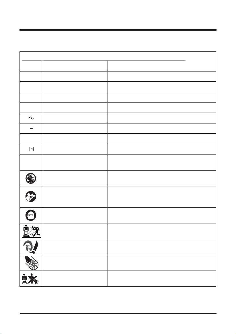
Some of the following symbols may be used on this product. Please study them and learn their
meaning. Proper interpretation of these symbols will allow you to operate the product better and safer.
SYMBOLS
n
o
SYMBOL NAME DESIGNATION/EXPLANATION
V Volts Voltage
A Amperes Current
Hz Hertz Frequency (cycles per second)
W Watts Power
min Minutes Time
Alternating Current Type of current
Direct Current Type or a characteristic of current
No Load Speed Rational speed, at no load
Class II Construction Double-insulated construction
/min Per Minute Revolutions, strokes, surface speed, orbits etc.,
per minute
Wet Conditions Alert Do not expose to rain or use in damp locations
Read The Operator’s Manual To reduce the risk of injury user must read and
understand operator’s manual before using this
product.
Eye and Head Protection Wear eye and head protection when operating
this equipment.
Ricochet Thrown objects can ricochet and result in personal
injury or property damage.
Spinning Rotor Danger – Keep hands and feet away from spinning
rotor. Spinning rotor can cause severe injury.
Keep Hands And Feet Away. Keep hands, feet away from the discharge area.
Keep Bystanders Away Keep all bystanders at least 50 ft. away.
5
6
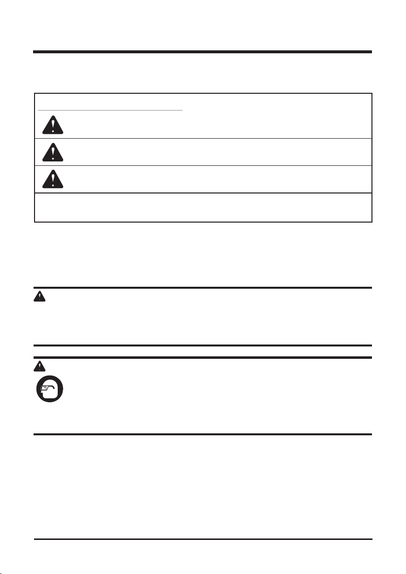
The following signal words and meanings are intended to explain the levels of risk associated
with this product.
SERVICE
Servicing requires extreme care and knowledge and should be performed only by a qualied
service technician. For service we suggest you return the product to your nearest AUTHORIZED
SERVICE CENTER for repair. When servicing, use only identical replacement parts.
W A R N I N G
To avoid serious personal injury, do not attempt to use this product until you have read this
Owner's Manual thoroughly and understand it completely. If you do not understand the warnings
and instructions in this Owner's Manual, do not use this product. Call the Toll-free Helpline (1-
888-909-6757) for assistance.
W A R N I N G
The operation of any power tool can result in foreign objects being thrown into your
eyes, which can result in severe eye damage. Before beginning power tool operation,
always wear safety goggles or safety glasses with side shields and, when needed, a
full face shield. We recommend Wide Vision Safety Mask for use over eyeglasses or
standard safety glasses with side shields. Always use eye protection which is marked
to comply with ANSI Z87.1.
SYMBOL SIGNAL MEANING
DANGER Indicates an imminently hazardous situation, which, if not
avoided, will result in death or serious injury.
WARNING Indicates a potentially hazardous situation, which, if not avoided,
could result in death or serious injury.
CAUTION Indicates a potentially hazardous situation, which, if not avoided,
may result in minor or moderate injury.
CAUTION (Without Safety Alert Symbol) Indicates a situation that may
result in property damage.
SYMBOLS
SAVE THESE INSTRUCTIONS
7
ELECTRICAL
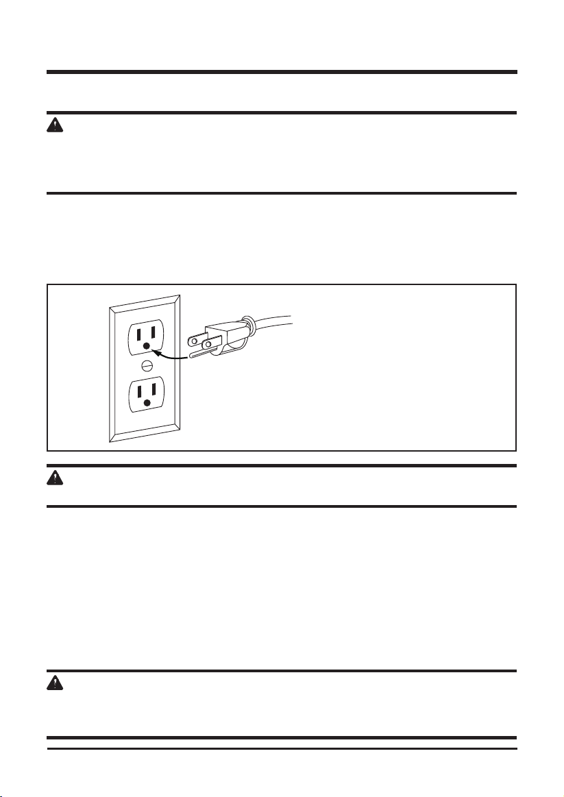
ELECTRICAL INFORMATION (See Figure 1)
W A R N I N G
To avoid electrical hazards, re hazards, or damage to the tool, use proper circuit protection. The
Snow Thrower is wired at the factory for 120 V operation. Connect to a 120 V, 15 A circuit and use
a 15 A time delayed fuse or circuit breaker. To avoid shock or re when the power cord is worn, cut,
or damaged in any way, replace it immediately.
This Snow Thrower has a 3-prong plug that is intended for use on a circuit that has a receptacle
like the one illustrated in Fig. 1.
Do not modify the power cord plug. If it does not match the electrical outlet, have the proper
outlet installed by a qualied electrician.
W A R N I N G
To avoid injury, when servicing the Snow Thrower, use only identical replacement parts.
GROUNDING INSTRUCTIONS
IN THE EVENT OF A MALFUNCTION OR BREAKDOWN, grounding provides the path of least
resistance for electrical current and reduces the risk of electric shock. This tool is equipped with
an electric cord that has a POLARIZED plug. The plug MUST be plugged into a matching outlet
that is properly installed and grounded in accordance with ALL local codes and ordinances.
DO NOT MODIFY THE PLUG PROVIDED. If it will not t the outlet, have the proper outlet
installed by a qualied electrician.
EXTENSION CORD
W A R N I N G
In order to reduce the risk of electric shock when operating this Snow Thrower, use only a CSA
listed extension cord that is approved for outdoor use, such as Type SJTW, 16AWG, and that has a
lower temperature rating of -40° F (-40° C).
Fig. 1
1) 3-prong plug
2) Receptacle with grounding conductor
ELECTRICAL
8
SAVE THESE INSTRUCTIONS
• Ground Fault Circuit Interrupter (GFCI) protection should be provided on the circuit(s) or
outlet(s) that will be used for this Snow Thrower. For an extra measure of safety, use a
receptacle that has built-in GFCI protection.
• The nameplate on the Snow Thrower indicates the voltage used. Do not connect the Snow
Thrower to an AC circuit that provides a different voltage from the voltage that is indicated on
the nameplate.
[Use the same format for the table as found in the le entitled "Recommended size of extension
cords".]
W A R N I N G
In order to prevent electric shock, use an extension cord that is suitable for outdoor use.
• Inspect the extension cord and the power cord on a regular basis. Look for deterioration,
cuts, or cracks in the insulation. Inspect the connections for damage. Repair or replace the
extension cord or the power cord if any damage is found.
• Verify that the rotor and all moving parts have come to a complete stop, and disconnect the
Snow Thrower from the power supply in order to prevent accidental start-ups before cleaning
or performing any inspections or repairs.
• Do not abuse the extension cord. Do not carry the Snow Thrower by the power cord or pull on
the cord in order to disconnect it from the receptacle.
• Keep the extension cord away from heat, oil, and sharp edges in order to prevent damage.
• If the extension cord is damaged in any manner while it is plugged in, disconnect it from the
outlet immediately.
• Avoid accidental start-ups. Do not carry the Snow Thrower with a nger on the switch while
it is plugged in. Verify that the switch is in the "OFF" position before plugging in the Snow
Thrower.
• Unplug the Snow Thrower and allow it to cool down before putting it into storage. Store the
Snow Thrower indoors.
• Unplug the Snow Thrower when it is not in use and before performing any maintenance or
repairs.
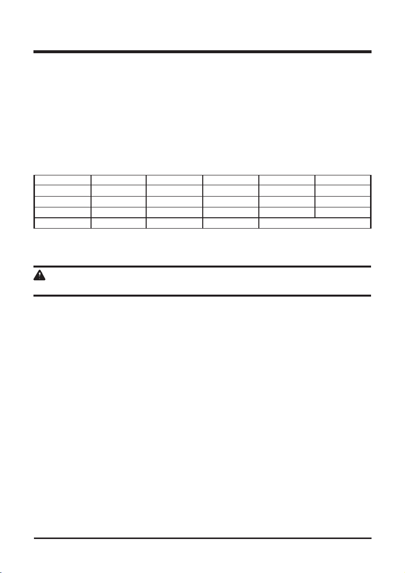
MINIMUM GAUGE FOR EXTENSION CORDS (AWG)
(WHEN USING 120 V ONLY)
Amp Rating Total Length of Cord in Feet (meters)
More Than Not More Than 25' (7.6 m) 50' (15 m) 100' (30.4 m) 150' (45.7 m)
0 6 18 16 16 14
6 10 18 16 14 12
10 12 16 16 14 12
12 16 14 12 Not Recommended
9
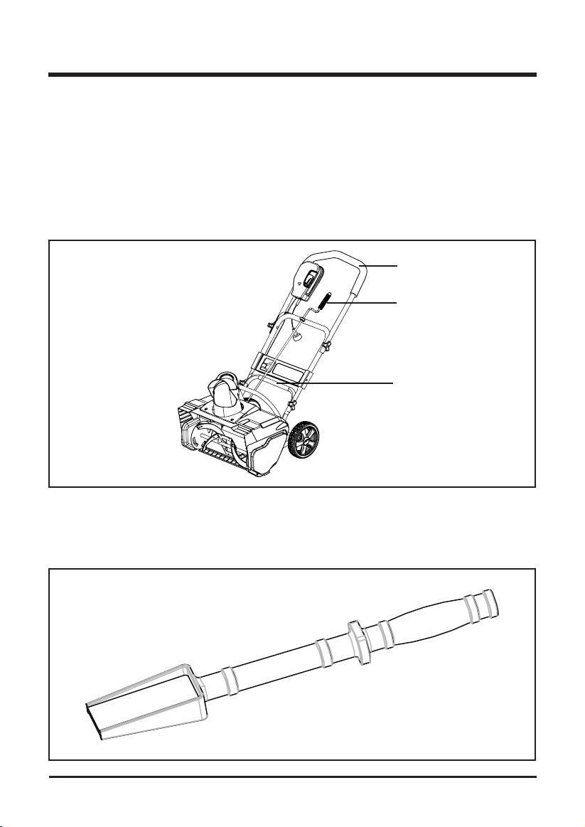
KNOW YOUR SNOW THROWER
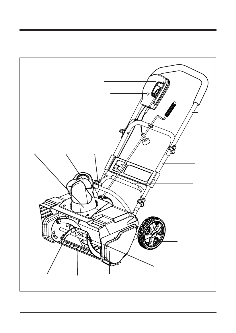
Fig. 2
Read this operator's manual and safety rules before operating your snow thrower. Compare the
illustration in Figure 2 to your snow thrower in order to familiarize yourself with the location of
various controls and adjustments. Save this manual for future reference.
Upper
Handle
Discharge
Directional
Control
Middle
Handle
Lower
Handle
Wheels
Cover Screws
Switch
Overload
Protector
Chute
deector
Discharge
chute
Scraper
Impeller
Belt Cover
Front
Handle

10
UNPACKING
This product has been shipped completely assembled.
• Carefully remove the product and any accessories from the box. Make sure that all items
listed in the packing list are included.
• Inspect the product carefully to make sure no breakage or damage occurred during shipping.
• Do not discard the packing material until you have carefully inspected and satisfactorily
operated the product.
• If any parts are damaged or missing, please call 1-888-909-6757 for assistance.
PACKING LIST
• Snow thrower
• Small rubber shovel
• Discharge directional control
• Chute deector
• Owner's Manual
W A R N I N G
If any parts are damaged or missing, do not operate this product until the parts are replaced.
Failure to heed this warning could result in serious personal injury.
W A R N I N G
Do not connect to power supply until assembly is complete. Failure to comply could result in
accidental starting and possible serious personal injury.
W A R N I N G
Do not attempt to modify this product or create accessories not recommended for use with this
product. Any such alteration or modication is misuse, and could result in a hazardous condition
leading to possible serious personal injury.
ASSEMBLY INSTRUCTIONS
11
W A R N I N G
Do not allow familiarity with this product to make you careless. Remember that a careless
fraction of a second is sufcient to inict serious injury.
W A R N I N G
Always wear safety goggles or safety glasses with side shields when operating power tools. Failure
to do so could result in objects being thrown into your eyes, resulting in possible serious injury.
W A R N I N G
Do not use any attachments or accessories not recommended by the manufacturer of this product.
The use of attachments or accessories not recommended can result in serious personal injury.
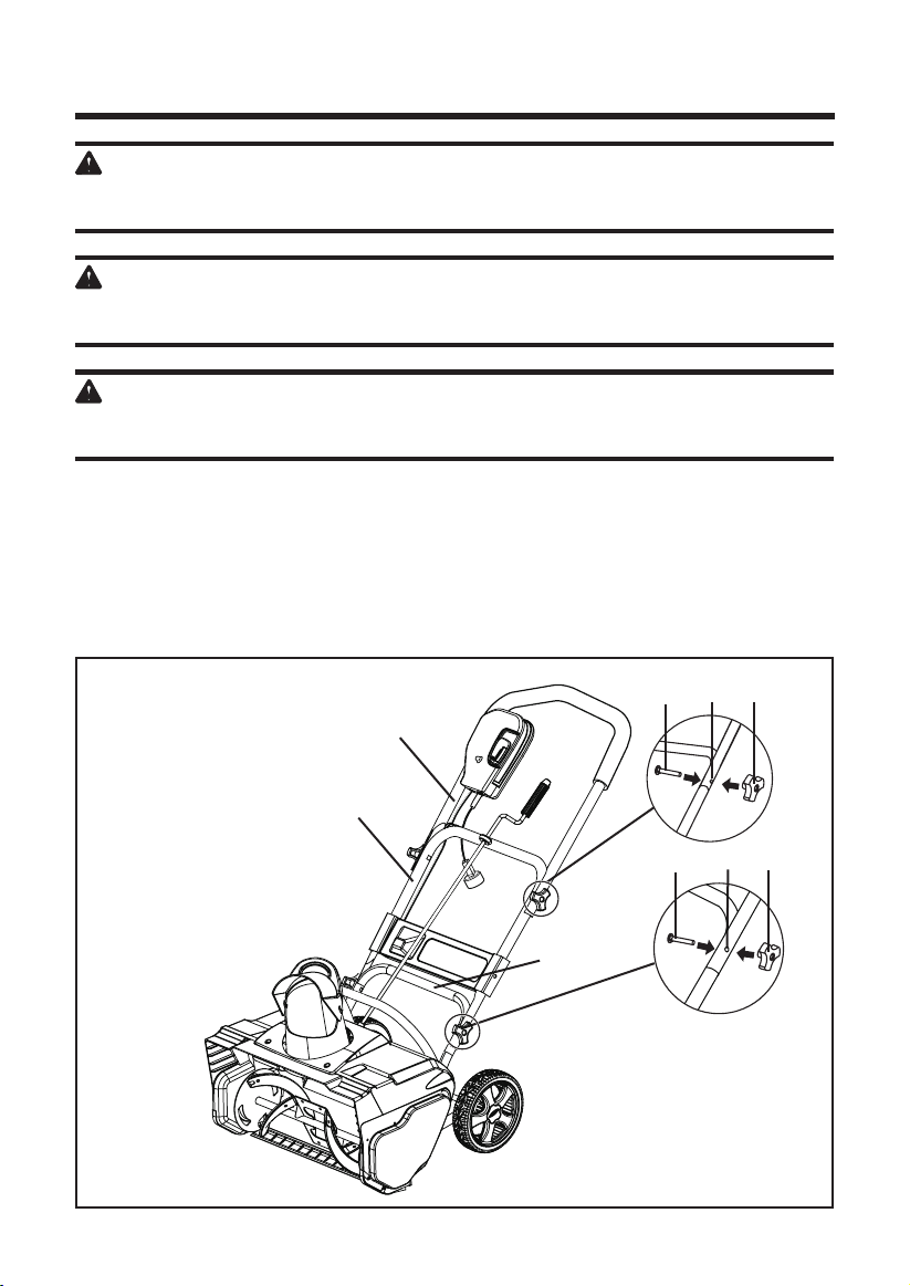
ASSEMBLING THE HANDLE (See Figure 3)
• Remove any packing material that may have been inserted between the upper and lower
handles for shipping purposes.
• Align the holes (4) on the upper handle (1) with the holes on the middle handle (2). Insert the
bolts (5), and use the wing nuts (6) to tighten them.
• Align the holes (7) on the middle handle (2) and the lower handle (3). Insert the bolts (5), and
tighten them using the wing nuts (6) provided.
ASSEMBLY INSTRUCTIONS
Fig. 3
3
1
2
5
5
6
67
4

12
ASSEMBLING THE DISCHARGE CHUTE (See Figure 4)
• Position the chute deector (1) over the discharge chute (2), and align the mounting holes.
• Insert a rubber washer (5) between the chute deector (1) and the discharge chute,
maintaining the alignment of the holes (3).
• Attach the chute deector to the discharge chute using a carriage bolt (4), 2 washers (5), and
a locknut (6).
• Insert a rubber washer (8) between the chute deector (1) and the discharge chute,
maintaining the alignment of the holes (10).
• Attach the chute deector to the discharge chute using 2 carriage bolts (7), 4 washers (8), and
2 locknuts (9).
Note: Do not overtighten the bolts.
ASSEMBLY INSTRUCTIONS
Fig. 4
1
2
3
4
5
5
6
7
89
10
13
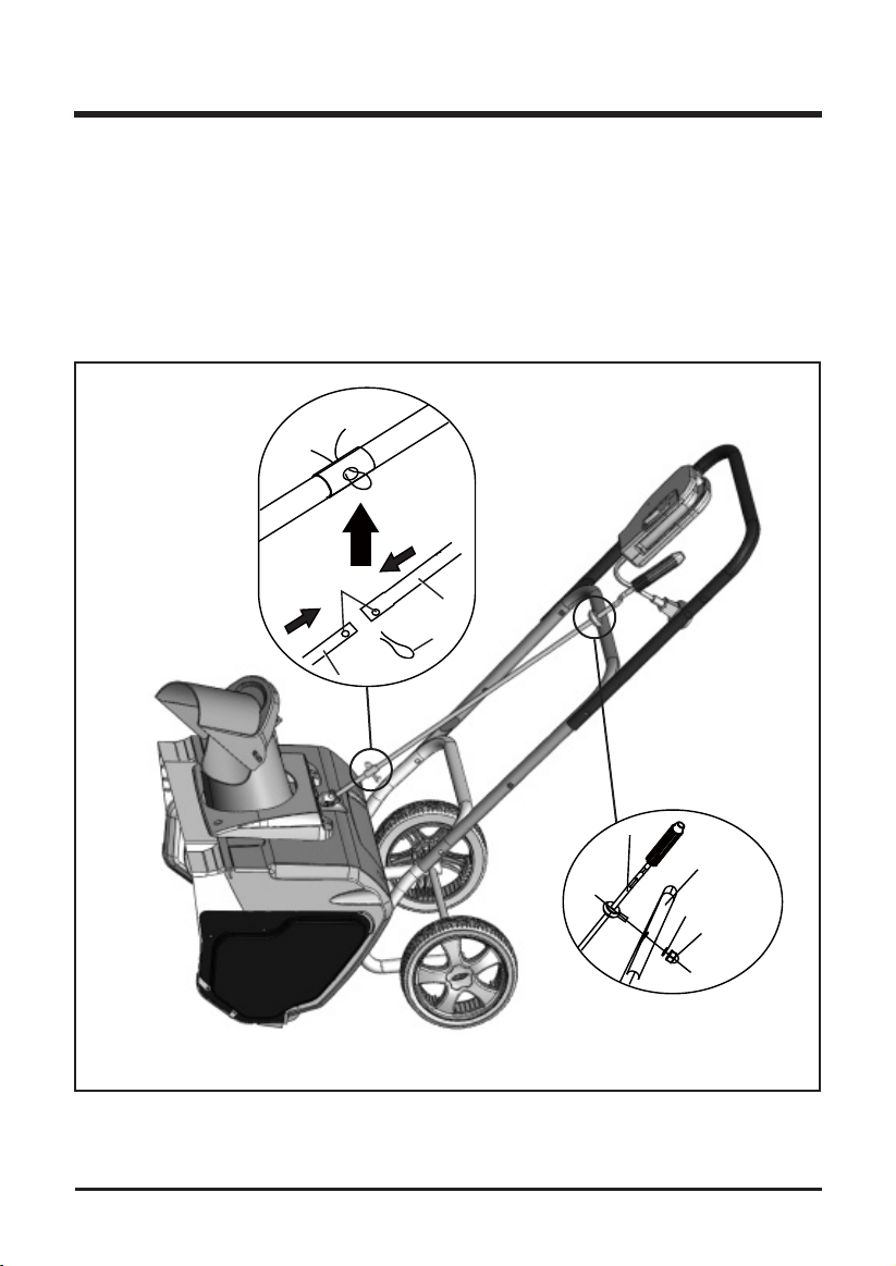
ASSEMBLING THE DIRECTIONAL CHUTE ARM TO DIRECTIONAL CHUTE
PINION (See Figure 5)
• Align the holes (1) on the directional chute arm (2) with the holes on the lower directional
chute arm (3). Insert the hitch pin (4). (Fig. 5.1)
ASSEMBLING THE DISCHARGE DIRECTIONAL ARM CONTROL TO THE CENTER
HANDLE (See Figure 5)
• Attach the directional chute arm (5) to the center handle (6) using a washer (7) and a locknut (8).
(Fig. 5.2)
ASSEMBLY INSTRUCTIONS
Fig. 5
Fig. 5.1
Fig. 5.2
1
2
5
6
7
8
3
4

STARTING THE SNOW THROWER
W A R N I N G
Avoid accidental start-ups. Verify that the operator is in the starting position when using the snow
thrower. In order to avoid serious injury, the operator and unit must be in a stable position when
starting the Snow Thrower.
USING THE SWITCH
This Snow Thrower is equipped with a special safety switch. In order to operate the switch, insert
one nger into the opening, and push the lever out so that it can be grasped along with the upper
handle. Pull the lever back in order to turn the Snow Thrower on, and hold it against the upper
handle in order to keep it running. To turn the Snow Thrower off, simply release the lever.
C A U T I O N
Do no attempt to override the operation of this safety switch.
OVERLOAD PROTECTION SWITCH
This Snow Thrower is equipped with an overload protection switch in order to protect the supply
circuit from short circuit overloads. Follow these steps if the switch pops out:
• Release the switch bar, and allow the Snow Thrower to stop and cool down for a minute.
• Press the overload switch in order to reset it. Resume operation (Fig. 2).
Follow these steps if the switch pops out again shortly after the rst time:
• Allow the Snow Thrower to stop and cool down for 15 to 30 minutes.
• After the Snow Thrower has cooled down, press the overload switch in order to reset it.
Resume operation.
If the overload protection switch does not stay in, or if it continues to pop out during operation,
contact the Toll-Free Helpline, at 1-888-909-6757.
OPERATING INSTRUCTIONS
14
OPERATING TIPS (See Figure 6)
W A R N I N G
If the Snow Thrower hits a foreign object while it is in use, the object could be thrown in the
direction of the operator or a bystander. Thrown objects could cause serious personal injury.
Keep the area to be cleared free of all foreign objects that may be picked up and thrown by the
rotor blades.
• Keep children and pets away from the operating area.
• Keep the area to be cleared free of stones, toys, or other foreign objects that the rotor blades
can throw. Such items may be covered by a snowfall and go unnoticed. If the Snow Thrower
strikes an obstruction or a foreign object during operation, stop the Snow Thrower, unplug the
extension cord, remove the obstruction, and inspect the Snow Thrower for damage.
• Rotate the chute crank clockwise in order to move the discharge chute to the left, or rotate it
counter-clockwise in order to move the chute to the right.
Note : T he chute crank makes a noise as it is turned. This is normal.
The deector handle (1) that is located on the top of the discharge chute controls the height of the snow
stream (Fig. 6).
Adjust the height of the snow stream by raising or lowering the chute deector
OPERATING INSTRUCTIONS
15
Fig. 6
1

ADJUSTING THE DIRECTION OF DISCHARGE (See Figure 7)
Snow can be discharged to the left, straight ahead, or to the right of the operator.
Follow these instructions in order to change the direction:
• Release the safety switch in order to stop the rotor.
NOTE: The control crank can revolve 810°. The discharge chute can rotate 180°. Do not force it.
• Turn the discharge directional control clockwise 360°. The vanes will turn approximately
80° to the right.
• Turn the discharge directional control counter-clockwise 360°. The vanes will turn
approximately 80° to the left.
W A R N I N G
If there is a gap between the discharge chute and the chute deector, snow and anything else that
can be picked up by Snow Thrower may y in the direction of the operator. Thrown objects could
cause serious personal injury.
• Do not force the chute deector too far forward so that a gap appears between the discharge
chute and the chute deector.
• Do not overtighten the locknuts that hold the chute deector in position to the point where it is
necessary to use excessive force in order to adjust the chute deector.
• Begin removing snow near the electrical outlet, and work outward. Work back and forth, and
not away from or toward the outlet.
• When turning at the end of a swath, step over the cord, and then turn the Snow Thrower.
• Overlap each swath, and discharge the snow in the direction of the wind whenever possible.
• Shave down large banks of snow by placing the Snow Thrower on the bank. Lift the Snow
Thrower by the primary and secondary handles only (Fig. 5). Allow the weight of the Snow
Thrower to shave down the bank in a back-and-forth motion.
• When clearing steps or deep drifts, hold the Snow Thrower by the primary and secondary
handles (Fig. 5), and use a swinging or sweeping motion.
W A R N I N G
When using the secondary handle, do not direct the snow discharge chute toward the operator
or toward bystanders. The Snow Thrower can throw foreign objects, which could cause serious
personal injury. When using the secondary handle, always turn the discharge chute in the opposite
direction from where the operator or bystanders are located.
• Keep the extension cord clear of obstructions, sharp objects, and all moving parts. Do not
pull sharply on the cord or abuse it in any manner. Inspect the extension cord for damage that
may result in an electric shock on a regular basis. If the extension cord becomes damaged in
any way, replace it immediately.
• Some controls and moving parts may freeze in certain cold and snowy weather conditions.
If any of the controls become hard to operate, stop the motor, disconnect the extension cord,
and inspect the Snow Thrower for frozen parts.
OPERATING INSTRUCTIONS
16
• Do not use excessive force when trying to operate frozen controls. Free all of the controls and
moving parts before using the Snow Thrower.
• When operating the Snow Thrower, keep the wheels 1" (2.5 cm) off the pavement by tipping
the Snow Thrower forward. This will help to prevent the snow from building up on the wheels.
• After clearing the snow, allow the motor run for a few minutes so that the ice doesn’t freeze
any moving parts. Then shut off the motor, wait for all moving parts to come to a complete
stop, and wipe the ice and snow off the Snow Thrower. Rotate the chute crank several times
in order to remove the snow from the Snow Thrower.
• Lock the Snow Thrower when it is not in use. Disconnect the extension cord.
SMALL RUBBER SHOVEL (See Figure 8)
This Snow Thrower comes with a small rubber shovel that can be used to shovel snow from
corners where the Snow Thrower cannot reach.
OPERATING INSTRUCTIONS
17
Fig. 8
Fig. 7
Primary
handle
Discharge
directional
control
Secondary
handle
MAINTENANCE
SERVICING
Servicing should be performed by a qualied technician. Replacement parts for this Snow
Thrower must be identical to the parts that they replace. If repairs are necessary, contact the
Toll-Free Helpline, at 1-888-909-6757.
Note: Identify the left and right sides of the Snow Thrower when standing in the normal operating position.
W A R N I N G
If the extension cord is plugged into the Snow Thrower, the Sno w T hrow er c ould start
accident ally wh ile the operator is performing maintenance on it, which could cause serious
personal injury. Disconnect the extension cord before performing any maintenance.
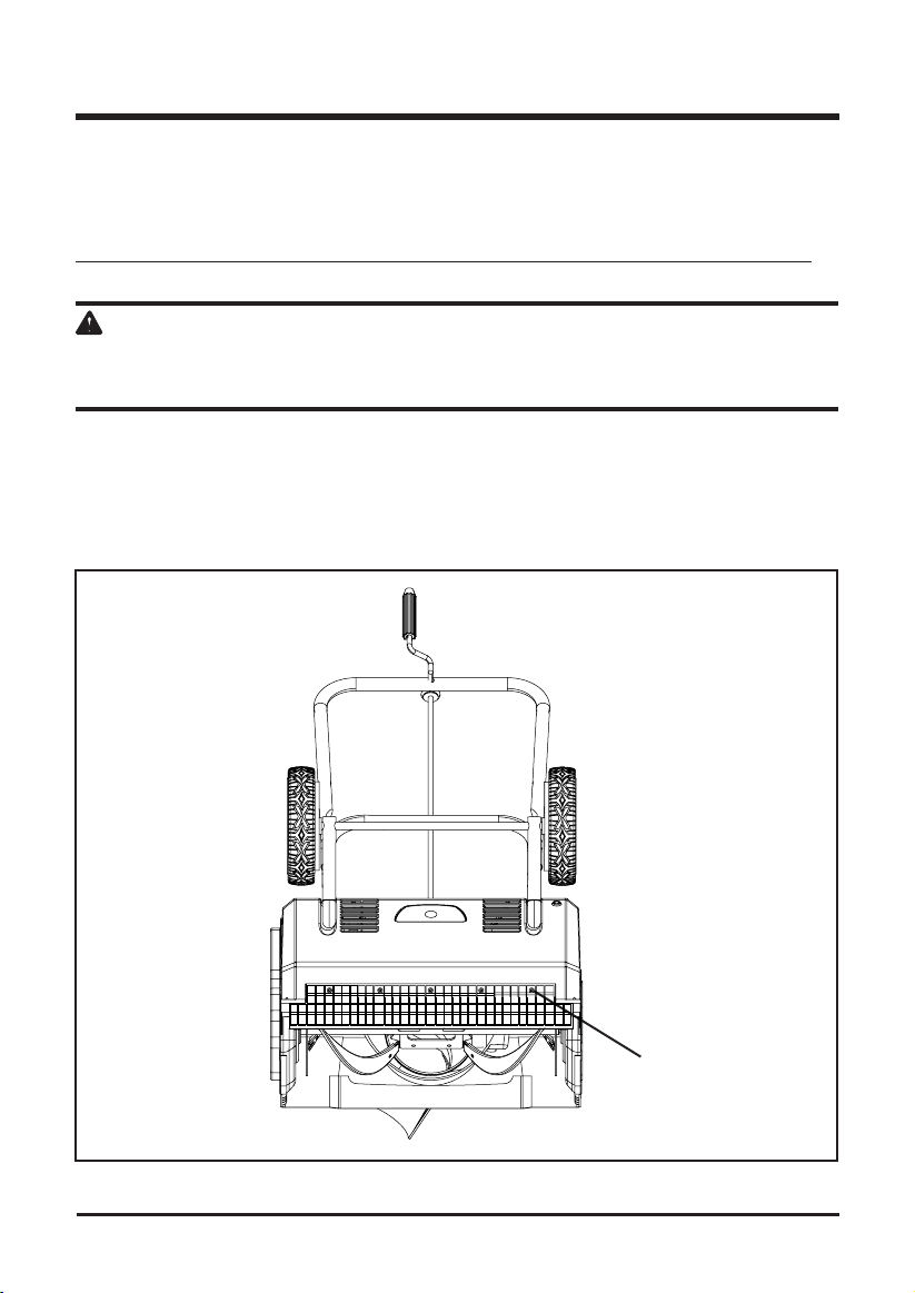
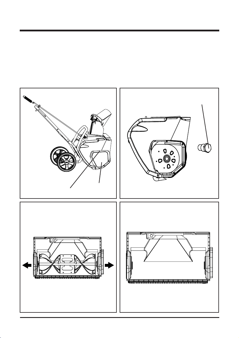
REPLACING THE SCRAPER (See Figure 9)
The scraper is located at the bottom of the rotor housing, as shown in Figure 9.
• Remove the 5 screws that secure the scraper to the Snow Thrower (Fig. 9).
• Install the new scraper, and attach it securely using the 5 screws.
Fig. 9
18
Screw
MAINTENANCE
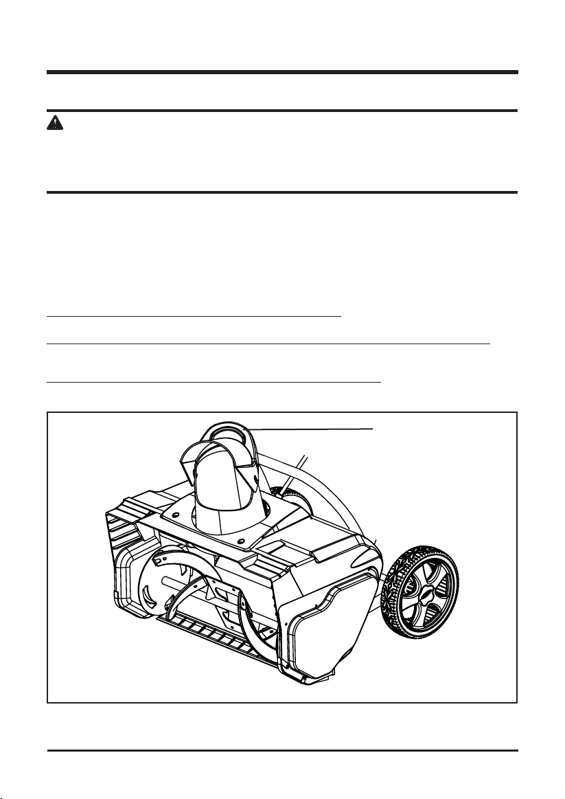
REPLACING THE ROTOR (See Figures 10-13)
• Remove the 4 screws that secure the right side cover to the frame of the Snow Thrower (Fig. 10).
• Remove the short shaft (Fig. 11).
• Push the sides of the housing out, as illustrated in Figure 12 and remove the rotor (Fig. 13).
• Install the new rotor, and reinstall the clip.
• Reinstall the right side cover, and secure it using the 4 screws.
19
Fig. 10
Fig. 12
Fig. 11
Fig. 13
Short shaft
Right side
cover
Screw
MAINTENANCE
20
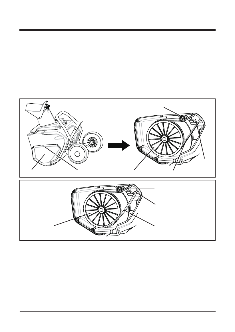
REPLACING THE LARGE BELT (See Figures 14-16)
• Remove the 4 screws that secure the left side plate to the frame of the Snow Thrower (Fig.
14). Remove the side plate.
• Pull the bearing away from the small pulley. Remove the belt from the large pulley and the
small pulley that is located inside the housing (Fig. 15).
• Position the new belt over the small pulley (Fig. 16).
• Rotate the rotor with the left hand while positioning the belt on the large pulley with the right
hand (Fig. 16).
• Install the left side cover, and secure it using the 4 screws.
STORAGE
• Run the Snow Thrower for a few minutes in order to melt any snow that may be left on the
Snow Thrower.
• Disconnect the extension cord from the Snow Thrower.
• Inspect the extension cord thoroughly for signs of wear or damage. Replace it if it is worn or damaged.
• Inspect the Snow Thrower thoroughly for worn, loose, or damaged parts. If any parts must be
repaired or replaced, contact the Toll-Free Helpline, at 1-888-909-6757.
• Store the extension cord with the Snow Thrower.
• Store the Snow Thrower in a clean, dry place. Cover it in order to provide added protection.
Fig. 14 Fig. 15
Fig. 16
Bearing
Bearing
Left side cover Large pulley
Large pulley
Small
pulley
Small
pulley
Belt
Belt
Screw

21
PROBLEM POSSIBLE CAUSE SOLUTION
Then handle is not The carriage bolts are not Adjust the height of the handle, and verify
in position. properly seated. that the carriage bolts are properly seated.
Tighten the knobs.
The Snow Thrower The power cord is disconnected Reconnect the cord, and use the cord
does not start. from the switch. restraint to keep the cord close to the
switch.
The switch is defective. Replace the switch.
The extension cord is not Connect the plug on the Snow Thrower to
connected to the plug. the extension cord.
The extension cord is not Plug the extension cord into a live 120 V
connected to the power source. AC, 60 Hz outlet.
The overload protection switch See the section entitled Overload
has popped out. Protection Switch (Page 14).
The motor is on, but The belt is damaged. Replace the belt (see the section entitled
the rotor does not Inspecting/Replacing the Drive Belt).
turn.
The Snow Thrower The scraper is worn. Replace the scraper (see the section
leaves a thin layer of entitled Replacing the Scraper).
snow behind.
TROUBLESHOOTING

22
GREENWORKS™ hereby warranties this product, to the original purchaser with proof of
purchase, for a period of four (4) years against defects in materials, parts or workmanship.
GREENWORKS™, at its own discretion will repair or replace any and all parts found to be
defective, through normal use, free of charge to the customer. This warranty is valid only for
units which have been used for personal use that have not been hired or rented for industrial/
commercial use, and that have been maintained in accordance with the instructions in the
owners’ manual supplied with the product from new.
ITEMS NOT COVERED BY WARRANTY:
1. Any part that has become inoperative due to misuse, commercial use, abuse, neglect,
accident, improper maintenance, or alteration; or
2. The unit, if it has not been operated and/or maintained in accordance with the owner's
manual; or
3. Normal wear, except as noted below;
4. Routine maintenance items such as lubricants, blade sharpening;
5. Normal deterioration of the exterior nish due to use or exposure.
GREENWORKS HELPLINE (1 888 90WORKS):
Warranty service is available by calling our toll-free helpline, 9am to 5pm EST. Monday – Friday
at 1 888 909 6757 (1 888 90WORKS).
TRANSPORTATION CHARGES:
Transportation charges for the movement of any power equipment unit or attachment are the
responsibility of the purchaser. It is the purchaser’s responsibility to pay transportation charges
for any part submitted for replacement under this warranty unless such return is requested in
writing by GREENWORKS.
LIMITED FOUR-YEAR WARRANTY
23
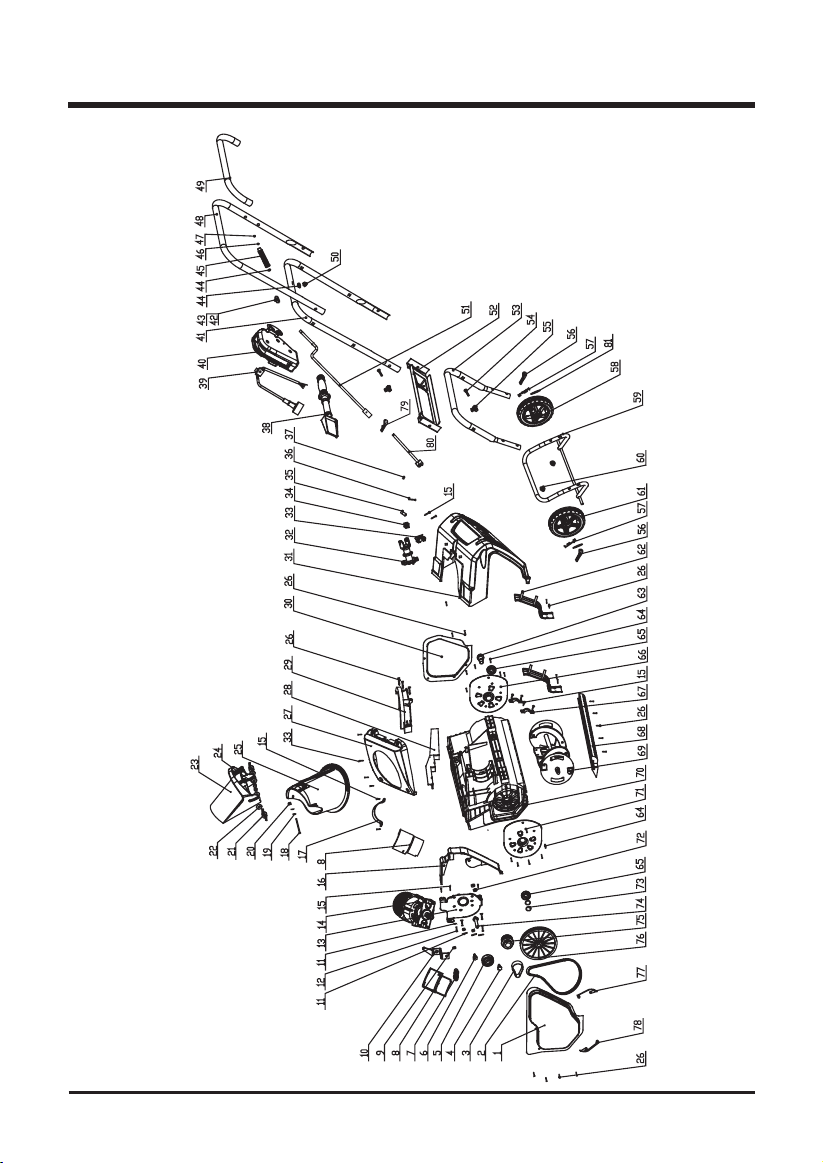
EXPLODED VIEW

24
ITEM NO. PART NO. DESCRIPTION QTY
1 33306100-10 Left side board 1
2 3290198 Belt 1
3 34901100 Strap 1
4 33212100 Tensioner x shaft 1
5 32104100 Tensioner bearing 1
6 33211100 Tensioner shaft 1
7 33903100 Tensioner spring 1
8 34165100 Motor vent cover 2
9 32201100 Locknut 7
10 33305100 Tensioner bracket 1
11 3290699 Washer 7
12 32203100 Cross screw 4
13 33301100-2 Motor support 1
14 31120100-1 Motor assembly 1
15 3220505 Screw 9
16 34120100-1 Waterproof bracket 1
17 33378100 Motor clamp 1
18 32208100 Cross screw 1
19 32210100 Washer 2
20 32209100 Nut 1
21 3410835-50 Knob 2
22 32215100 Washer 4
23 34111100-10 Chute deector 1
24 32216100 Hex screw 2
25 34110100-10 Discharge chute 1
26 32207100 Cross screw 20
27 34104100-10 Out chute cover 1
28 34121100A Waterproof support 2
29 34106100-1 Inlet chute cover 1
30 33307100-10 Right side board 1
31 34102100-10 Rear cover 1
32 34160100 Pinion bracket 1
33 34161100 Plate 1
34 34162100 Square bushing 1
35 33260100 Pin 1
36 32288100 Screw 1
37 32901261 Locknut 1
38 34118100-10 Snow spade 1
39 31107100A Pigtail cable 1
40 3630235-7 Switch assembly 1
41 33207100-10 Middle handle 1
42 3330499 Screw 1
PARTS LIST

25
ITEM NO. PART NO. DESCRIPTION QTY
43 3420199 Rubber 1
44 3290299 Washer 2
45 3410499A-10 Handle 1
46 33306699 Washer 1
47 32901251 Retaining ring 1
48 32208100-10 Upper handle 1
49 3490137-1 Soft grip sponge 1
50 3290599 Nut 1
51 33214100-10 Rear rocker 1
52 33310100-10 Panel 1
53 33205100A-10 Front handle 1
54 3220436 Bolt 4
55 3410835-8 Knob 4
56 3290135 Split pin 2
57 34108229A-10 Wheel cover 2
58 34204229B-10 8” Wheel (right) 1
59 33206100A-10 Lower handle 1
60 34250100 Rubber sleeve 2
61 34204229A-10 8” Wheel (left) 1
62 33304100 Front support 2
63 33201100A Short shaft 1
64 32206100 Cross screw 12
65 32102100 Waterproof bearing 2
66 33309100 Right support 1
67 34158100 Inner cord clamp 4
68 34105100-1 Vane 1
69 31118100 Impellor assembly 1
70 34101100-10 Front cover 1
71 33308100 Left support 1
72 3220651 Nut 2
73 32217100 Washer 3
74 33203100A Pulley wheel support shaft 1
75 31110100A Pulley wheel assembly 1
76 34109100-1 Driver wheel 1
77 33274100-10 Right barrier chip 1
78 33273100-10 Left barrier chip 1
79 3320643 Hitch pin 1
80 33214100-11 Upper rocker 1
81 3220898 Washer 2
PARTS LIST

26
NOTES

27
NOTES

TOLL-FREE HELPLINE: 1-888-90WORKS
(888.909.6757)
Rev: 01 (05-18-10) Printed in China on 100% recycle material
