Read all safety rules and instructions carefully before operating this tool.
Owner’s Manual
TOLL-FREE HELPLINE: 1-888-90WORKS
(888.909.6757)
www.GreenWorksTools.com
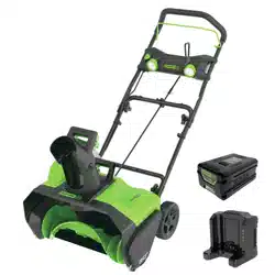
40V 20'' Cordless Snow Thrower
26272

2
Contents .............................................................................................................................. 2
Product specications .......................................................................................................... 2
Safety information ............................................................................................................. 3-5
Symbols ............................................................................................................................ 6-7
Know your snow thrower ...................................................................................................... 8
Assembly ........................................................................................................................ 9-14
Operation ...................................................................................................................... 15-18
Maintenance ................................................................................................................. 19-22
Troubleshooting ................................................................................................................. 23
Warranty ............................................................................................................................ 24
Exploded View / Parts List ............................................................................................ 25-28
PRODUCT SPECIFICATIONS
40V 20'' CORDLESS SNOW THROWER
Motor ...............................................................................................40V brushless motor
Battery type ............................................................................................ 40V Lithium-ion
No-load speed ............................................................................................... 1, 9 0 0 RPM
Working width ......................................................................................................... 20 in.
Wheels ..................................................................................................................... 7 in.
Weight (without battery) .......................................................................................... 33 lbs
CONTENTS
Cold Weather Operation: Lithium Ion batteries can be safely used from temperatures ranging
from -20 degrees to 45 degrees Celsius. NOTE: Do not store or charge battery outside. Battery
must be charged and stored indoors prior to use of the snow thrower.
Battery may not properly start if it’s temperatures is -20˚C or lower. If unit does not start remove
battery from snow thrower. Place battery on charger and allow to charge for 10 minutes to allow
battery to warm. Remove from charger and install in Snow thrower for use.

3
SAFETY INFORMATION
FOLLOW THESE RULES WHILE OPERATING THE SNOW THROWER
IMPORTANT
READ AND UNDERSTAND ALL INSTRUCTIONS. Failure to follow all instructions listed below
may result in electric shock, re, and/or serious personal injury.
• Walk. Do not run.
• Verify that the snow thrower is not in contact with anything before turning it on.
• Stay away from the discharge chute and impeller openings at all times. Keep face, hands, and
feet away from concealed, moving, or rotating parts.
• Be attentive when using the snow thrower, and stay alert for holes in the terrain and other
hidden hazards or trafc.
• Do not use the snow thrower on a gravel or crushed rock surface. Use extreme caution when
crossing gravel/crushed rock drives, walks, or roads.
• Move up and down slopes when clearing snow. Do not go across a slope. Use caution when
changing direction. Do not use this Snow Thrower to clear snow from steep slopes.
• Do not attempt to use the snow thrower on a roof or on any steeply inclined slippery surface.
• Do not operate the snow thrower if the guards, plates, and other safety protective devices are
not in place.
• Do not operate the snow thrower near glass enclosures, automobiles, trucks, window wells,
drop-offs, etc. without properly adjusting the angle of the snow discharge. Keep children and
pets away from the work area.
• Do not force or overload the snow thrower. The snow thrower will perform better and safer
when it is used at the rate that it was designed to work at.
• Do not operate the snow thrower at high speeds on slippery surfaces. Look behind when
backing up and exercise caution.
• Do not direct the discharge toward anyone. Do not allow anyone to move in front of the snow
thrower while it is in use.
• Wear safety glasses or goggles that meet ANSI Z87.1 standards.
• Use the snow thrower in daylight or in good articial light. If using at night, turn on the LED
lights and be aware of your surroundings.
• To avoid accidental start-ups, remain in the starting position when turning the snow thrower
on. The operator and the Snow Thrower must be in a stable position during start-up. See the
section titled Starting/Stopping Instructions.
• Use this snow thrower only for the purposes it was designed.
• Do not overreach. Always keep proper footing and balance.
• Hold the snow thrower with both hands while it is in use. Keep a rm grip on the handles.
• If the impeller does not rotate freely due to ice, thaw the snow thrower thoroughly before
attempting to use it.
• Keep the impeller clear of debris.

4
SAFETY INFORMATION
• Do not attempt to clear the impeller while the motor is running.
• Keep clothing and body parts away from the impeller.
• Stop the motor when stopped or when moving from one location to another.
• Remove the battery pack when it is being transported and when it is not in use.
• After striking a foreign object, turn the snow thrower off and remove the battery pack, and then
inspect it for damage. Repair any damage before restarting and using the snow thrower.
• If the snow thrower starts to vibrate abnormally, stop the snow thrower immediately and attempt
to determine the cause. Vibration is generally an indication of danger.
• Stop the motor and remove the battery pack whenever the operator is not in the operating
position, before unclogging the impeller, and before making any repairs, adjustments, or
inspections.
• Do not discharge snow onto public roads or near moving trafc.
• Allow the snow thrower to run for a few minutes after clearing snow in order to prevent moving
parts from freezing.
• Only use identical replacement parts and accessories for this snow thrower. The use of
nonidentical parts or accessories could lead to serious injury to the user or damage the snow
thrower, and will void the warranty.
• Do not pick up the snow thrower while it is running. The snow thrower is designed to travel
along the ground.
• Dress Properly – Do not wear loose clothing or jewelry. They can be caught in moving parts.
• Wear rubber boots when operating the snow thrower.
• Operation of the snow thrower in the hand-held position is unsafe, except in accordance with
the special instructions for such use provided in the operator’s manual.
• Store Idle Snow Throwers Indoors – When not in use, snow throwers should be stored indoors
in dry, locked-up place – out of reach of children.
GENERAL SAFETY RULES
• Verify that the snow thrower is secure while transporting.
• Store the snow thrower in a dry that will prevent unauthorized use or damage. Keep out of the
reach of children.
• Keep handles dry, clean, and free of debris. Clean the snow thrower after each use. Refer to
the Maintenance Section in the this manual for more information.
• If the labels on the snow thrower become defaced or start to lift off, contact the toll-free
helpline, at 1-888-909-6757.
• Keep these instructions in a safe place for future reference. Refer to them often, and use them to
instruct other users. Anyone who uses this snow thrower must read these instructions carefully.
• Maintain the snow thrower with care. Follow the instructions for lubricating and changing
accessories.

SAFETY INFORMATION
5
WARNING(PROPOSITION 65)
Some dust created by power sanding, sawing, grinding, drilling and other construction activities
contains chemicals known to the state of California to cause cancer, birth defects or other
reproductive harm. Some examples of these chemicals are:
• Lead from lead-based paints,
• Crystalline silica from bricks and cement and other masonry products, and
• Arsenic and chromium from chemically-treated lumber.
Your risk from these exposures varies, depending on how often you do this type of work. To reduce
your exposure to these chemical: work in a well ventilated area, and work with approved safety
equipment, such as those dust masks that are specially designed to lter out microscopic particles.
SAVE THESE INSTRUCTIONS
CAUTION
USE ONLY GREENWORKS APPROVED REPLACEMENT BATTERIES, OTHER BATTERIES
MAY CAUSE INJURY OR DAMAGE TO THE SNOW THROWER. USE ONLY WITH
GREENWORKS 40V BATTERIES (Model#: 29472) and GREENWORKS 40V CHARGER
(Model#: 29482).
6
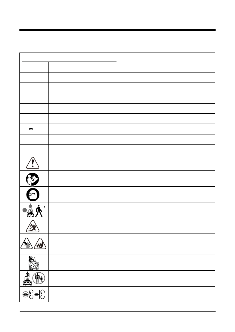
SYMBOLS
6
Some of the following symbols may be used on this product. Please study them and learn their
meaning. Proper interpretation of these symbols will allow you to operate the product better and safer.
SYMBOL DESIGNATION/EXPLANATION
V Voltage
A Current
Hz Frequency (cycles per second)
Wh Watt Hour - Energy Storage Capacity
Ah Amp Hour - Current Capacity
DC Direct current
Type or a characteristic of current
RPM Revolutions per minute
/min Revolutions, strokes, surface speed, orbits etc., per minute
Indicates a potential personal injury hazard.
To reduce the risk of injury user must read and understand operator’s manual
before using this product.
Always wear safety glasses with side shields that are marked to comply with
ANSI Z87.1.
Stop the motor and remove the battery before leaving the machine.
Thrown objects can ricochet and result in personal injury or property damage
Danger – Keep hands and feet away from openings while the machine is running.
Do not use hands to unclog chute. Stop motor and remove the battery before
removing debris.
Keep hands, feet away from the discharge area.
Keep bystanders a safe distance from the machine.
Stay away from moving parts. Keep all guards and shields in place.
STOP
STOP
7
The following signal words and meanings are intended to explain the levels of risk associated
with this product.
ENVIRONMENTAL PROTECTION
Waste electrical products should not be disposed of with household waste. Please
recycle where facilities exist. Check with your local authority or retailer for recycling
advice.
The battery contains material which is hazardous to you and the environment. It must
be removed and disposed of separately at a facility that accepts lithium-ion batteries.
SERVICE
Servicing requires extreme care and knowledge and should be performed only by a qualied
service technician. For service we suggest you return the product to your nearest AUTHORIZED
SERVICE CENTER for repair. When servicing, use only identical replacement parts.
WARNING
To avoid serious personal injury, do not attempt to use this product until you have read this
Owner's Manual thoroughly and understand it completely. If you do not understand the warnings
and instructions in this Owner's Manual, do not use this product. Call the Toll-free Helpline (1-
888-909-6757) for assistance.
WARNING
The operation of any power tool can result in foreign objects being thrown into your
eyes, which can result in severe eye damage. Before beginning power tool operation,
always wear safety goggles or safety glasses with side shields and, when needed, a
full face shield. We recommend Wide Vision Safety Mask for use over eyeglasses or
standard safety glasses with side shields. Always use eye protection which is marked
to comply with ANSI Z87.1.
SYMBOL SIGNAL MEANING
DANGER Indicates an imminently hazardous situation, which, if not
avoided, will result in death or serious injury.
WARNING Indicates a potentially hazardous situation, which, if not avoided,
could result in death or serious injury.
CAUTION Indicates a potentially hazardous situation, which, if not avoided,
may result in minor or moderate injury.
CAUTION (Without Safety Alert Symbol) Indicates a situation that may
result in property damage.
SYMBOLS
SAVE THESE INSTRUCTIONS
8
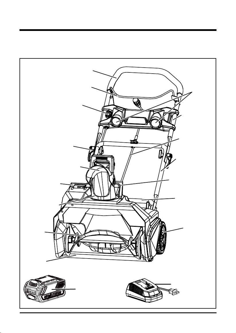
KNOW YOUR SNOW THROWER
Fig. 1
Read this operator's manual and safety rules before operating your snow thrower. Compare the
illustration in Figure 1 to your snow thrower in order to familiarize yourself with the location of
various controls and adjustments. Save this manual for future reference.
Greenworks
40V Charger
(Model#:29482)
Greenworks
40V Battery
(Model#:29472)
Battery
compartment
LED lights
Upper handle
Middle handle
Carrying or lifting
handle (For
transport only)
Chute
control rod
Lower handle
Wheel
Handle bar
Bail switch
Impeller
Scraper
Chute deector
Cam lock
Discharge chute
Safety switch
button
9
UNPACKING
• Carefully remove the product and any accessories from the box. Make sure that all items
listed in the packing list are included.
• Inspect the product carefully to make sure no breakage or damage occurred during shipping.
• Do not discard the packing material until you have carefully inspected and satisfactorily
operated the product.
• If any parts are damaged or missing, please call 1-888-909-6757 for assistance.
PACKING LIST
• Snow thrower
• Upper chute control rod
• Lower chute control rod
• Middle handle assembly
• Chute deector
• Greenworks 40V Battery (Model#: 29472)
• Greenworks 40V Charger(Model#: 29482)
• (2) Cam locks
• (2) Bolts
• (4) Handle knobs
• (1) Hitch pin
• Owner's Manual
WARNING
If any parts are damaged or missing, do not operate this product until the parts are replaced.
Failure to heed this warning could result in serious personal injury.
WARNING
Do not install the battery until assembly is complete. Failure to comply could result in accidental
starting and possible serious personal injury.
WARNING
Do not attempt to modify this product or create accessories not recommended for use with this
product. Any such alteration or modication is misuse, and could result in a hazardous condition
leading to possible serious personal injury.
ASSEMBLY INSTRUCTIONS
10
ASSEMBLY INSTRUCTIONS
Fig. 2
7
4
6 5
1
2
3
9
8
WARNING
Do not allow familiarity with this product to make you careless. Remember that a careless
fraction of a second is sufcient to inict serious injury.
WARNING
Do not use any attachments or accessories not recommended by the manufacturer of this product.
The use of attachments or accessories not recommended can result in serious personal injury.
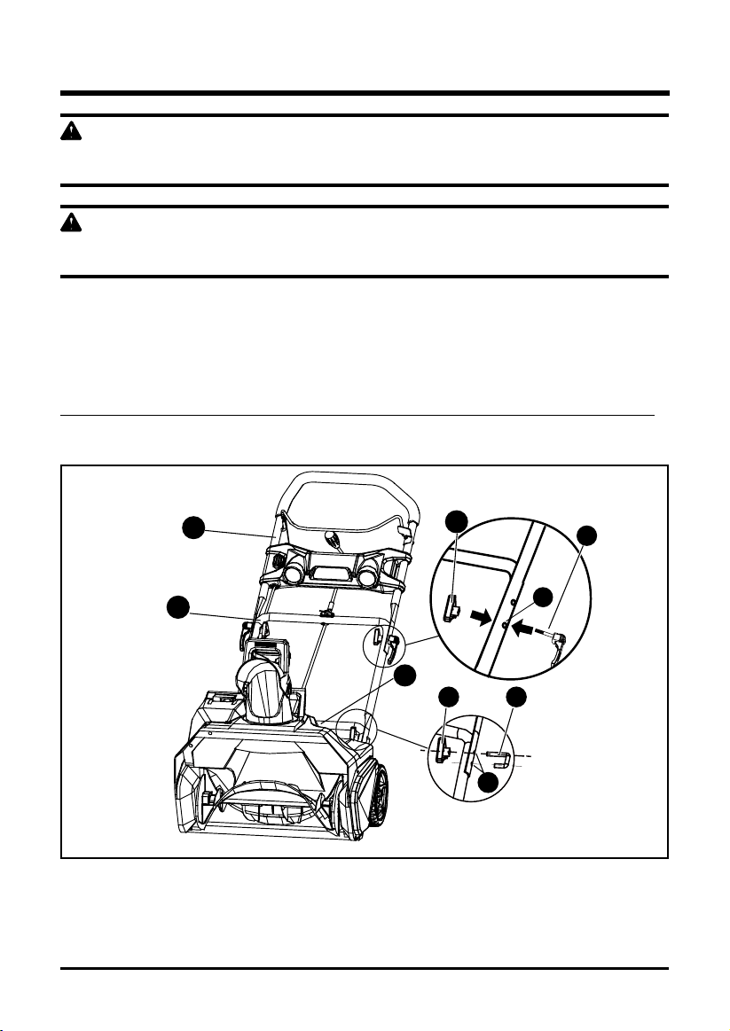
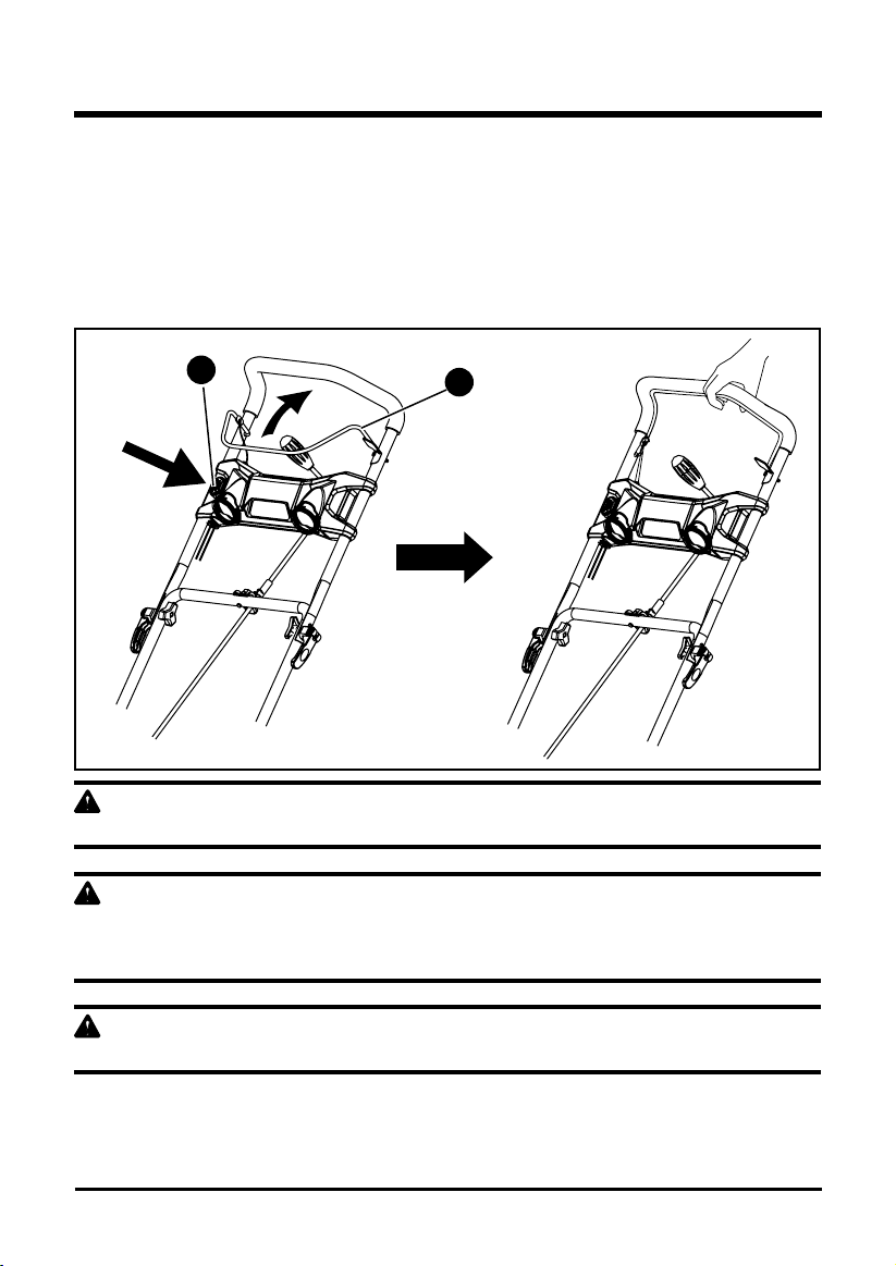
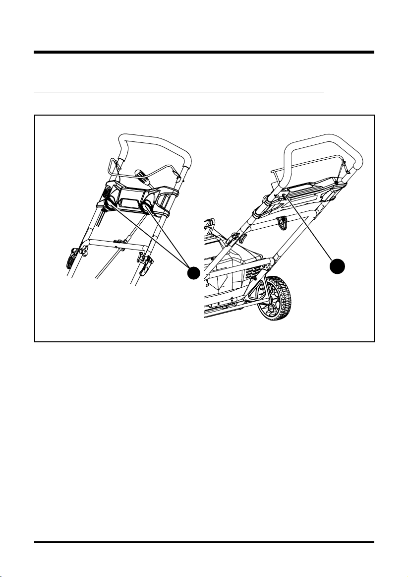
ASSEMBLING THE HANDLE (See Figure 2)
• Align the holes (4) on the middle handle (2) and the lower handle (3). Insert the bolts (5), and
use the handle knobs (6) to tighten them.
• Align the hole (7) on the middle handle (2) and the upper handle (1). Insert the cam locks (8)
and tighten them with the handle knobs (9) provided. Once tightened, close the cam locks to
secure them in place.
NOTE: If the upper handle is loose or separated from the middle handle, tighten the cam lock handle knobs
by turning them clockwise. Do not overtighten the handle knobs.
11
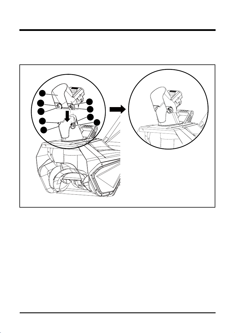
ASSEMBLING THE DISCHARGE CHUTE (See Figure 3)
Push the chute deector (1) until the latching tabs (2) on either side click into the slots (3) and
the posts (4) on either side click into the keyed holes (5).
ASSEMBLY INSTRUCTIONS
Fig. 3
1
3
2
4
4
2
5
3
5
12
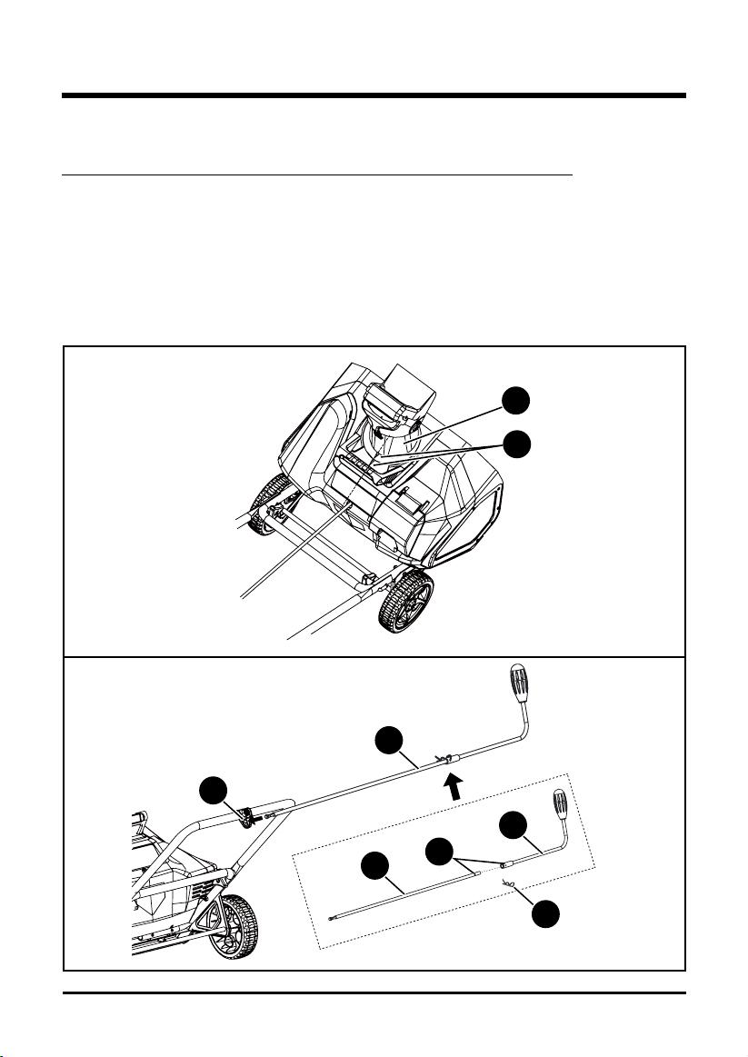
INSTALLING THE CHUTE CONTROL ROD (See Figure 4)
• Position the discharge chute (1) so that it faces forward.
NOTE: Align the arrow (2) on the discharge chute with the arrow on the housing.
(Fig. 4.1)
• Align the holes (3) on the upper chute control rod (4) with the holes on the lower chute control
rod (5). Insert the hitch pin (6). Insert the end of the chute control rod (7) through the keyed
hole (8) in the bracket that is attached to the top of the middle handle. (Fig.4.2)
• Ensure that the handle (9) of the chute control rod points upward, and insert the rod into the
keyed hole (10) in the back of the housing. (Fig.4.3)
• Firmly push the rod into the keyed hole in the back of the housing until it snaps into place.
ASSEMBLY INSTRUCTIONS
1
2
Fig. 4.1
Fig. 4.2
4
5
8
7
6
3

• Rotate the handle on the chute control rod to ensure that it moves in the same direction as the
chute. (Fig.4.4)
13
ASSEMBLY INSTRUCTIONS
Fig. 4.4
Fig. 4.3
10
9
ASSEMBLY INSTRUCTIONS
14
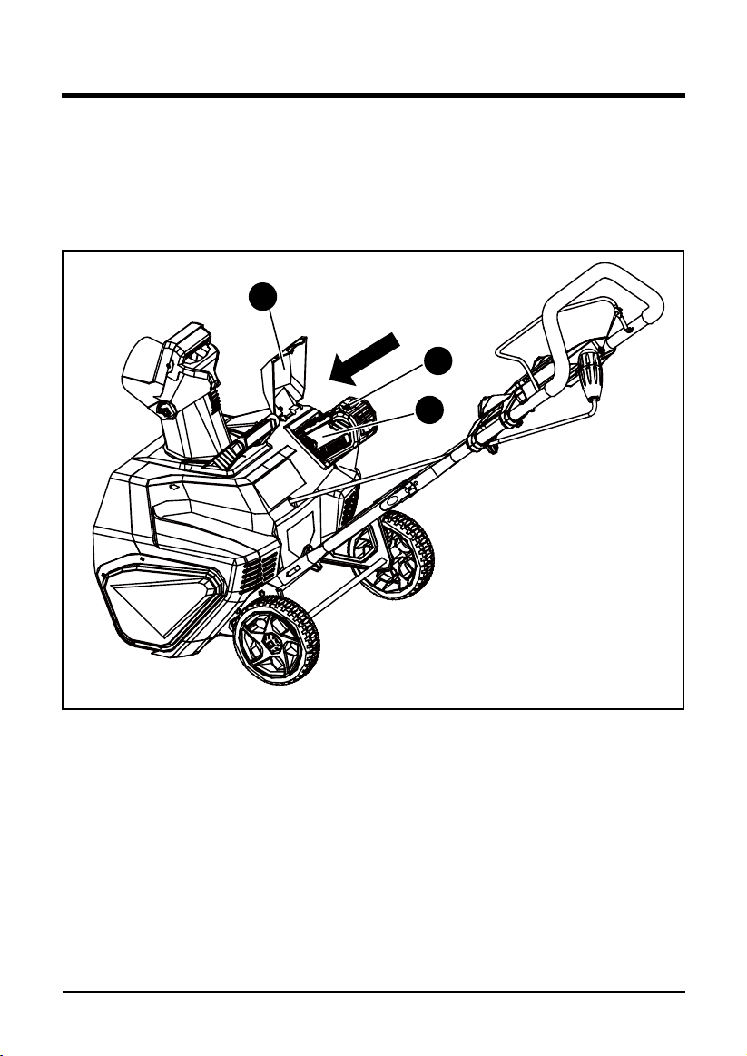
TO INSTALL BATTERY PACK (See Figure 5)
• Open the battery compartment cover (1).
• Slide the battery (2) down to lock it into position. The battery is fully inserted into the snow
thrower when you hear an audible “click”.
• Close the battery compartment cover (1).
TO REMOVE BATTERY PACK (See Figure 5)
• Release your grip on the ON/OFF switch bar lever to stop the snow thrower.
• Press and hold the battery latch button (3) at the bottom of the battery pack.
• Remove battery pack from the snow thrower.
Fig. 5
3
1
2
OPERATING INSTRUCTIONS
15
POWERING ON AND OFF (See Figure 6)
• To power on, rst press the safety switch button (1).
• While pressing the safety switch button with one hand, use your other hand to simultaneouly
pull the bail switch (2) toward you. Once the machine powers on, release the safety switch
button and proceed with operation. The snow thrower can only be started by pressing the
safety switch button rst, followed by squeezing the bail switch; reverse operation will not start
the machine.
• To power off, release your grip on the bail switch.
CAUTION
Do not attempt to override the operation of the safety switch button or bar lever.
WARNING
The operation of any snow thrower can result in foreign objects being thrown into the eyes, which
can cause severe eye damage. Always wear safety glasses while operating the snow thrower
and while performing any adjustments or repairs.
WARNING
Keep bystanders a safe distance from the machine.
INSPECT THE CLEARING AREA. Remove all stones, sticks, wire, bones, and other debris that
might be thrown by the rotating impeller.
Fig. 6
1
2
OPERATING INSTRUCTIONS
UTILIZING THE LED LIGHTS (See Figure 7)
• To utilize the LED lights (1) for night time snow removal, activate the LED light switch (2).
NOTE: After you have nished using your snow thrower, remember to turn off the light switch.
16
2
Fig. 7
1
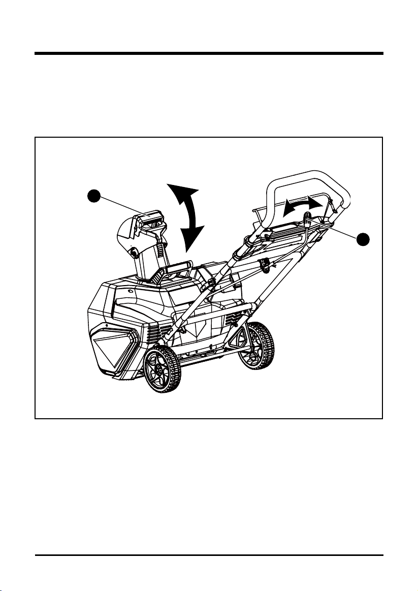
ADJUSTING THE DISCHARGE CHUTE AND CHUTE DEFLECTOR (See Figure 8)
• To adjust the discharge chute, rotate the handle (1) on the chute control rod in the direction
that you wish to direct the snow stream.
• To adjust the chute deector (and therefore the height of the snow stream), squeeze the
trigger (2) and raise or lower the chute deector.
OPERATING INSTRUCTIONS
17
Fig. 8
2
1

OPERATING TIPS
WARNING
If the Snow Thrower hits a foreign object while it is in use, the object could be thrown in the
direction of the operator or a bystander. Thrown objects could cause serious personal injury.
Keep the area to be cleared free of all foreign objects that may be picked up and thrown by the
impeller.
• Keep the area of operation free of foreign objects that can become thrown by the impeller.
Perform a thorough inspection of the area since some objects may be hidden from view by
surrounding snow. lf the snow thrower hits an obstruction or picks up a foreign object during
use, stop the snow thrower, remove the battery, remove the obstruction, and inspect the unit
for damage. Repair or replace any damaged part before restarting and operating the unit.
• Keep children, pets, and bystanders away from the area of operation. Be aware that the
normal noise of the machine when turned on may make it difcult for you to hear approaching
people.
• When moving the snow thrower, use the wheels on one side as the pivot point. Slightly tilt the
snow thrower on this pivot point to move it forward or backward.
• Start your clearing path outward, throwing snow in a back and forth motion. To clear in the
opposite direction, pivot the snow thrower on its wheels. Make sure to overlap clearing paths.
• Note the wind direction. If possible, move in the same direction as the wind so that the snow
is not thrown against the wind (and thus back onto you and on the just cleared path).
• Do not push the snow thrower with excessive force. You should push the machine gently and
at a consistent speed in accordance with the unit's throw rate.
• Some parts of the snow thrower may freeze under extreme temperature conditions. Do not
attempt to operate the snow thrower with frozen parts. If the parts freeze while the snow
thrower is in use, stop the snow thrower, remove the battery, and inspect for frozen parts.
Free all parts before restarting or operating the snow thrower. Never force controls that have
frozen.
• When working on pebbles, gravel, or unpaved surfaces, avoid throwing loose surface material
along with the snow by pushing down on the handle to raise the scraper at the base of the unit
above the pebbles or gravel.
• Cold Weather Operation: Lithium Ion batteries can be safely used from temperatures ranging
from -20 degrees to 45 degrees Celsius. NOTE: Do not store or charge battery outside.
Battery must be charged and stored indoors prior to use of the snow thrower.
• If the Snow thrower does not start initially remove battery from snow thrower. Place battery on
charger and allow to charge for 10 minutes. Remove from charger and install in Snowthrower
for use. The start-up issue may be caused from the battery being too cold. To avoid this issue,
ensure battery is stored in a dry cool place for storage and charging and leave indoors until
ready for use.
OPERATING INSTRUCTIONS
18

MAINTENANCE
SERVICING
Servicing should be performed by a qualied technician. Replacement parts for this Snow
Thrower must be identical to the parts that they replace. If repairs are necessary, contact the
Toll-Free Helpline, at 1-888-909-6757.
Note: Identify the left and right sides of the Snow Thrower when standing in the normal operating position.
WARNING
If the battery pack is installing into the snow thrower, the snow thrower could start accidentally
while the operator is performing maintenance on it, which could cause serious personal injury.
Remove the battery pack before performing any maintenance.
19
STORAGE
• Run the snow thrower for a few minutes in order to melt any snow that may be left on the snow
thrower.
• Wipe the snow thrower off with a dry cloth before storage. This will help prevent ice building
up on the unit and parts freezing.
• Remove the battery and store it in a cool dry location, if possible. Charge the battery every six
months when not in use in order to increase its life.
• Inspect the snow thrower thoroughly for worn, loose, or damaged parts. If any parts must be
repaired or replaced, contact the Toll-Free Helpline, at 1-888-909-6757.
• Store the snow thrower in a clean, dry place. Cover it in order to provide added protection.
• Always store battery and charger indoors.
MAINTENANCE
20
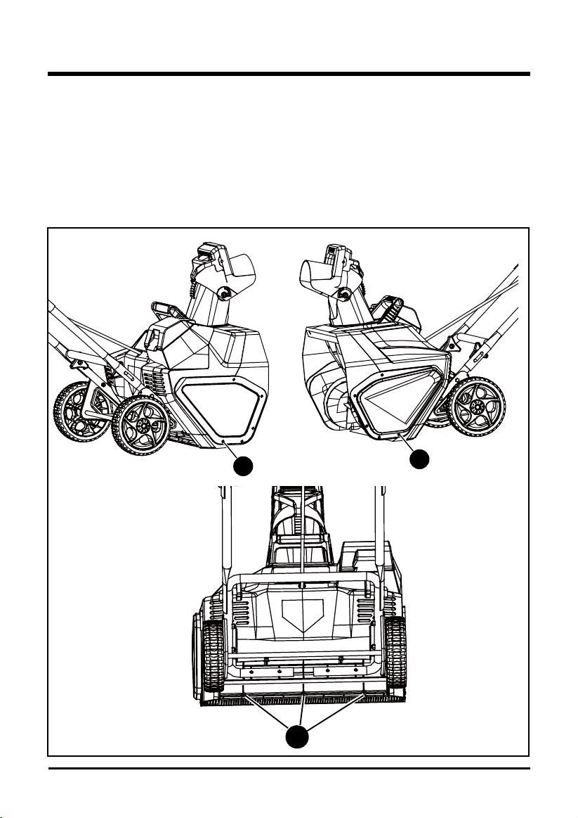
REPLACING THE SCRAPER (See Figure 9)
The scraper is located at the bottom of the impeller housing.
• Ensure that the battery is not installed in the tool.
• Remove the screw (1) from each side plate that holds the scraper and 3 screws (2) from under
the machine that secure the scraper to the machine.
• Remove and discard the old scraper.
• Install the new scraper, and fasten it securely with the 5 screws that you previously removed.
Fig. 9
1
1
2
MAINTENANCE
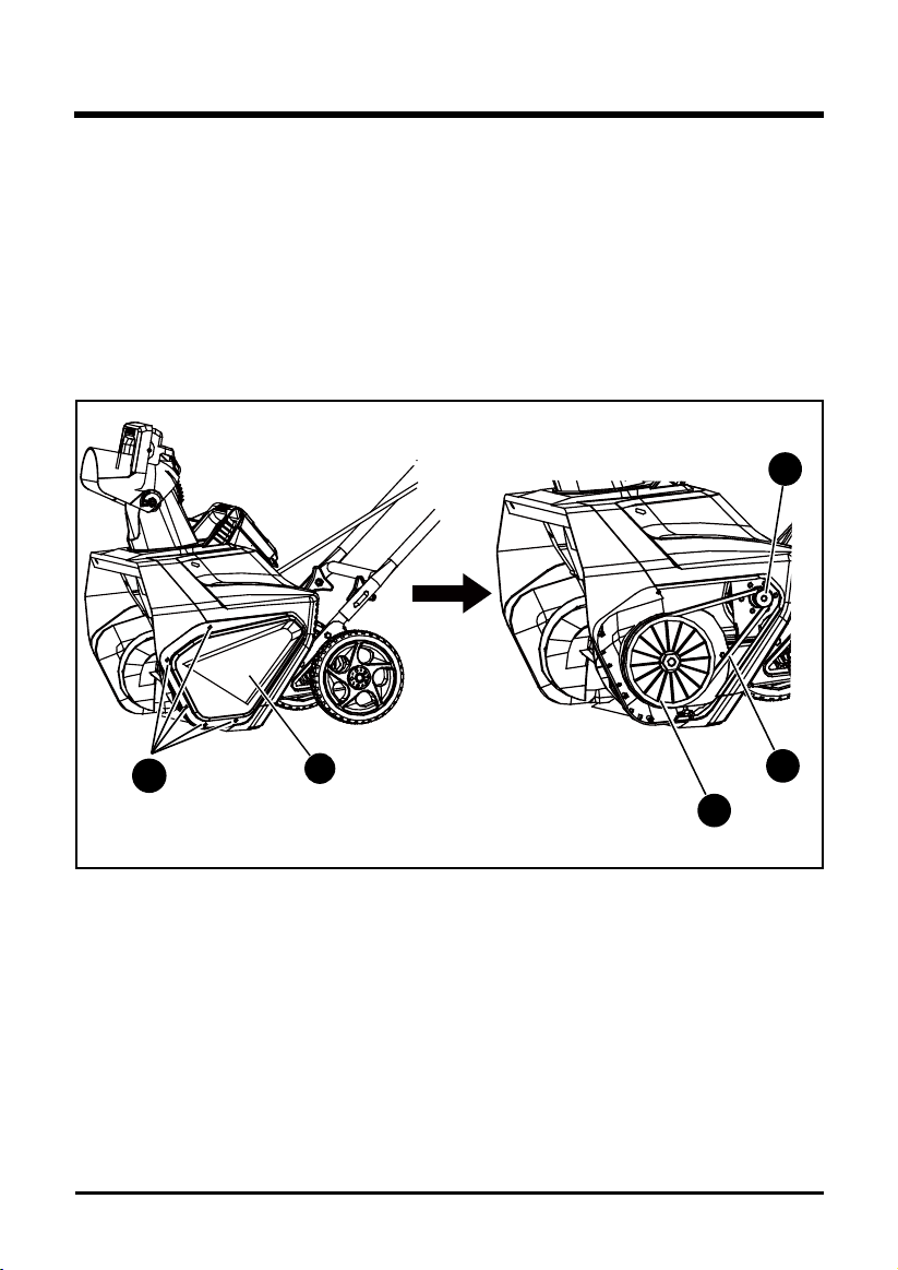
REPLACING THE DRIVE BELT (See Figures 10)
• Ensure that the battery is not installed in the tool.
• Remove the 5 screws (1) that secure the left side plate (2) to the frame of the snow thrower.
Remove the side cover.
• Remove the old belt (3) from the small pulley (5) and large pulley (4).
• Loop one end of the new belt over the small pulley.
• Rotate the impeller with the left hand while positioning the belt on the large pulley with the
right hand.
• Install the left side cover, and secure it using the 5 screws that you previously removed.
21
3
5
4
Fig. 10
1
2
4
5
6
7
8
9
10
11
MAINTENANCE
22
REPLACING THE IMPELLER (See Figures 11-13)
• Remove the 5 screws (1) that secure the right side cover (2) to the frame of the snow thrower.
• Remove the nut (3).
• Remove the 5 screws (4) that secure the left side cover (5) to the frame of the snow thrower.
• Remove the belt (6).
• Using a socket wrench, remove the the large pulley (7).
• Remove the 5 screws (8) that secure the left side plate (9) and remove the left side plate.
• Pull the axle (10) and remove the old impeller (11).
• Install the new impeller.
• Reinstall the left side plate, large pulley, belt and left side cover.
• Reinstall the nut and right side cover.
Fig. 12Fig. 11
Fig. 13
1
2
3

23
TROUBLESHOOTING
PROBLEM POSSIBLE CAUSE SOLUTION
Then handle is not The bolts are not properly Make sure the bolts are correctly installed
in position. seated. through the handle bars. Check to see if
the hand knobs are tight.
Refer to Assembling the Handle section in
this manual.
The snow thrower The battery is not charged. Charge the battery by following the
doesn't start. procedures in the battery and charger
manual.
The switch is defective. Have the switch replaced by an authorized
service center.
Battery is too cold. Remove battery from snow thrower. Place
battery on charger and allow to charge for
10 minutes. Remove from charger and
install in Snow thrower for use.
The battery is not attached to Check the connection between the motor
the motor. connector and the battery.
Battery may require service or Call toll free helpline, at 1-888-909-6757
replacement. or replace battery.
The motor is on, but The belt is damaged. Replace the belt (see the section entitled
the impeller does not Inspecting/Replacing the Drive Belt).
turn.
The snow thrower The scraper is worn. Inspect the scraper for wear or damage.
leaves a thin layer of Replace the scraper(see the section
snow behind. entitled Replacing the Scraper).

24
GREENWORKS™ hereby warranties this product, to the original purchaser with proof of
purchase, for a period of four (4) years against defects in materials, parts or workmanship.
GREENWORKS™, at its own discretion will repair or replace any and all parts found to be
defective, through normal use, free of charge to the customer. This warranty is valid only for
units which have been used for personal use that have not been hired or rented for industrial/
commercial use, and that have been maintained in accordance with the instructions in the
owners’ manual supplied with the product from new.
Battery and charger carries a two (2) years warranty against defects in workmanship and
materials. Batteries must be charged in accordance with the operator’s manuals directions and
regulations in order to be valid.
ITEMS NOT COVERED BY WARRANTY:
1. Any part that has become inoperative due to misuse, commercial use, abuse, neglect,
accident, improper maintenance, or alteration; or
2. The unit, if it has not been operated and/or maintained in accordance with the owner's
manual; or
3. Normal wear, except as noted below;
4. Routine maintenance items such as impeller, blade sharpening;
5. Normal deterioration of the exterior nish due to use or exposure.
GREENWORKS HELPLINE (1 888 90WORKS):
Warranty service is available by calling our toll-free helpline, 9am to 5pm EST. Monday – Friday
at 1 888 909 6757 (1 888 90WORKS).
TRANSPORTATION CHARGES:
Transportation charges for the movement of any power equipment unit or attachment are the
responsibility of the purchaser. It is the purchaser’s responsibility to pay transportation charges
for any part submitted for replacement under this warranty unless such return is requested in
writing by GREENWORKS.
LIMITED FOUR-YEAR WARRANTY
25
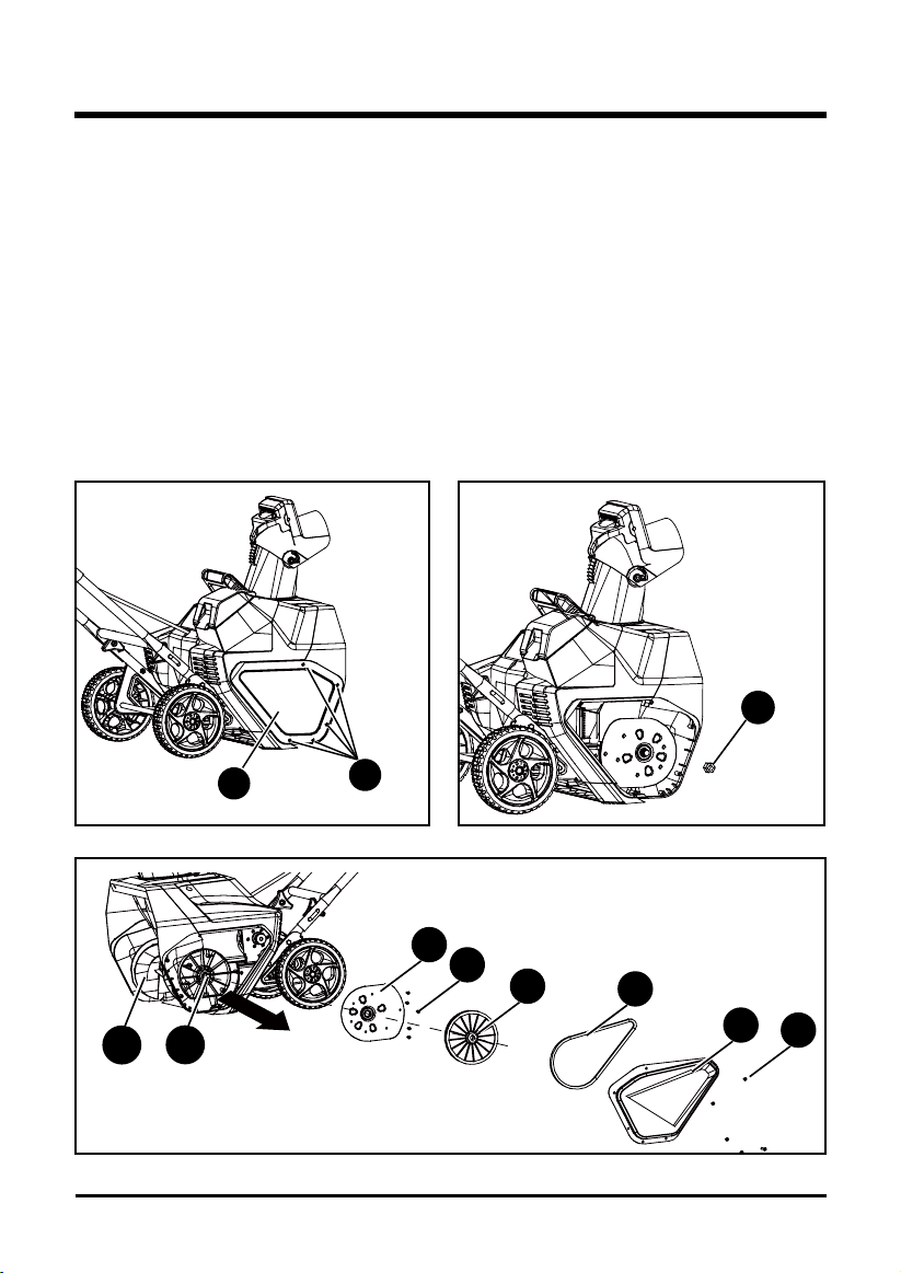
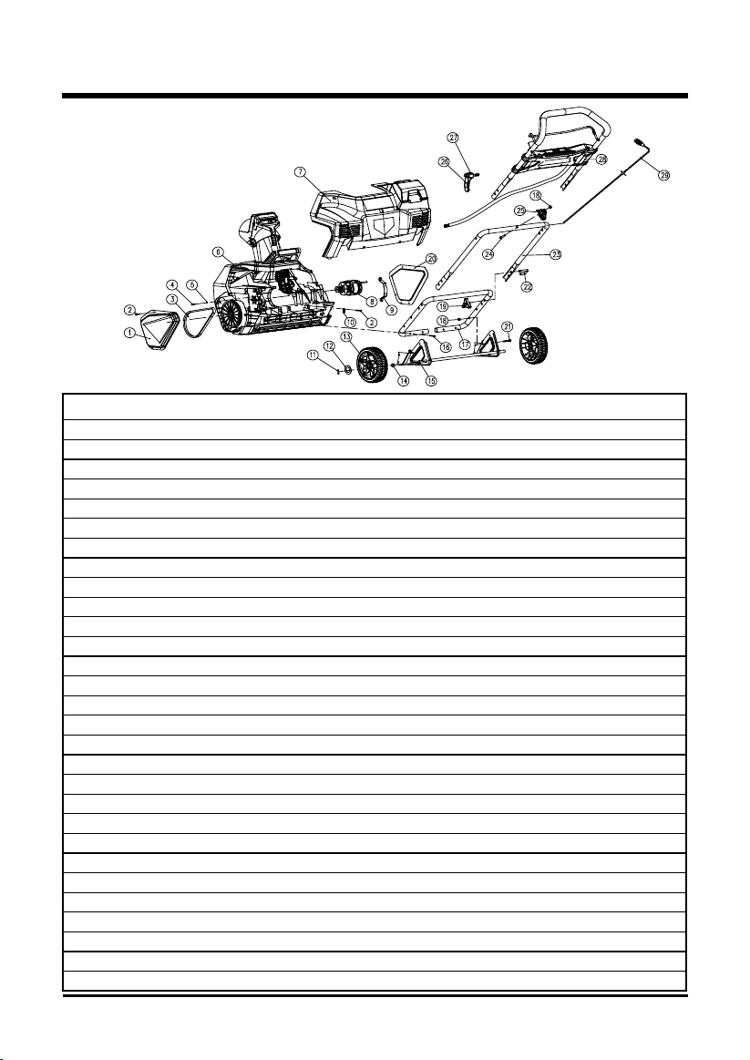
EXPLODED VIEW / PARTS LIST
ITEM NO. PART NO. DESCRIPTION QTY
1 332041205 Left side cover 1
2 32205877 Screw 20
3 329151205 Belt 1
4 32206575 Screw M5x8 4
5 3290250 Washer 4
6 311011201 Front cover assembly 1
7 311021201 Rear cover assembly 1
8 361011201 Motor 1
9 332031205 Motor clamp 1
10 3410801 Wire clamp 1
11 3290135 Split pin 2
12 3220898 Washer 2
13 34103486-7 7" wheel assembly 2
14 332151205 Rubber sleeve 2
15 332021205 Wheel bracket assembly 1
16 32201699 Screw 4
17 333031205 Lower handle 1
18 32222301A Nut M6 5
19 3410835-4 Knob 4
20 332051205 Right side cover 1
21 322011205 Bolt M6x30 4
22 333041205 U bolt 4
23 333021205 Middle handle 1
24 32226121 Screw 1
25 341131205-1 Bracket for the chute control rod 1
26 31102467 Cam lock assembly 2
27 34103466-1 Cam lock block 2
28 311031201 Handle bar assembly 1
29 311041208 Chute control rod assembly 1
26
EXPLODED VIEW / PARTS LIST
ITEM NO. PART NO. DESCRIPTION QTY
6 311011201 Front cover assembly 1
6-1 332061205 Link block 1
6-2 341171205-1 Impeller 1
6-3 339011205 Right driving block 1
6-4 34109100-12 Drive wheel 1
6-5 32217100 Washer 1
6-6 311111205 Left side plate 1
6-7 332111205 Bushing 2
6-8 339021205 Left driving block 1
6-9 332011205 Motor xed plate 1
6-10 341011205-1 Front cover 1
6-11 341031205 Discharge chute 1
6-12 31121205 Chute deector 1
6-13 341061205 Discharge chute base 1
6-14 341071205 Small gear 1
6-15 341091205 Gear seat 1
6-16 341081205 Big gear 1
6-17 32902250A Nut M12 1
6-18 311131205 Right side plate 1
6-19 332121205 Axle for the impeller 1
6-20 36201630 PCB board 1
6-21 341101205 Motor support 1
6-22 341111205 Scraper 1
27
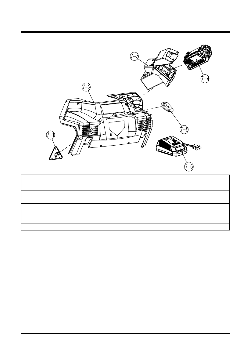
EXPLODED VIEW / PARTS LIST
ITEM NO. PART NO. DESCRIPTION QTY
7 311021201 Rear cover assembly 1
7-1 341121205 Connecting base 1
7-2 341021205 Rear cover 1
7-3 311041201 Battery compartment assembly 1
7-4 31104975 Greenworks 40V battery 1
7-5 342011205 Rubber bushing 1
7-6 31102998 Greenworks 40V charger 1
28
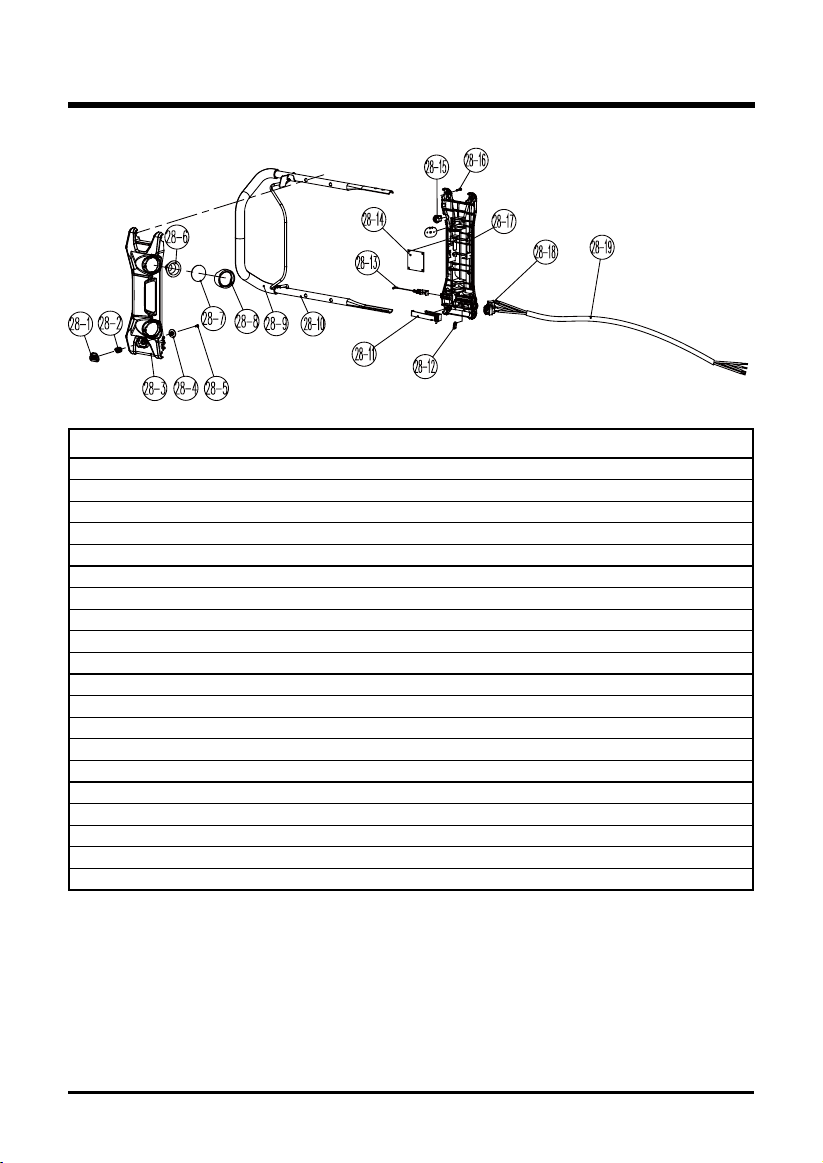
EXPLODED VIEW / PARTS LIST
ITEM NO. PART NO. DESCRIPTION QTY
28 311031201 Handle bar assembly 1
28-1 34136486-2 Safety switch button 1
28-2 33401229A Spring 1
28-3 341141205 Faceplate 1
28-4 341201205 Switch pressure head 1
28-5 3220735N Screw 1
28-6 333011108 Parabolic reector 2
28-7 341051108 Lamp screen 2
28-8 341061108-1 Light head housing 2
28-9 341011171 Soft grip sponge 1
28-10 333011205 Upper handle 1
28-11 311081205 Slider block assembly 1
28-12 3410801 Wire clamp 2
28-13 311091205 Start cable assembly 1
28-14 36202630 Circuit board 1
28-15 363051205 LED light switch 1
28-16 32205877 Screw 10
28-17 341151205 Lower cover 1
28-18 3630299 Switch 1
28-19 311101208 Cord assembly 1

TOLL-FREE HELPLINE: 1-888-90WORKS
(888.909.6757)
Rev: 01 (09-11-14) Printed in China on 100% recycle material