说明书
技术要求:
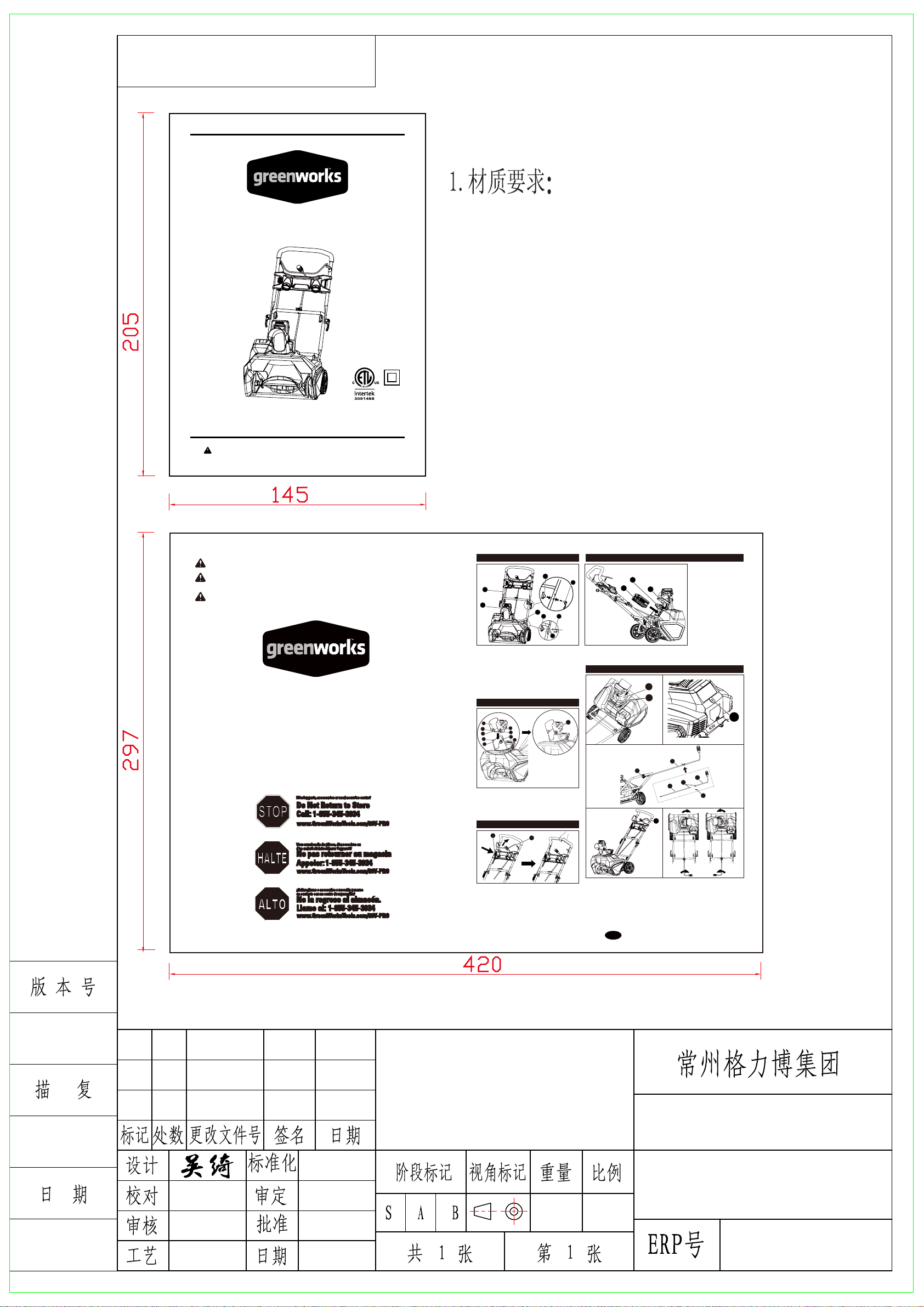
2.尺寸:145x205mm(刀模)
3.说明书为单色印刷,要求无色差、无污点;
4.胶钉,裁切均匀、无连页。
5.以封样为准。
60g双胶纸,页数:96p, 美款塑料袋
388011206B
388011206B
145
420
205297
2601302
20”80V无刷扫雪机(裸机)
(Greenworks US)
Read all safety rules and instructions carefully before operating this tool.
Owner’s Manual
TOLL-FREE HELPLINE: 1 (855) 345-3934
www.greenworkstools.com/80V-PRO
80V Cordless Snow Thrower
2601302
SNW80201
80V Cordless Snow Thrower
Souffleuse sans fil de 80V
Máquina quitanieve inalámbrica de 80V
Q
GUÍA PARA COMIENZO RÁPIDO
GUIDE DE DÉMARRAGE RAPIDE
UICK START GUIDE
Model # / Modèle # / Modelo #: 2601302
WARNING:
AVERTISSEMENT:
Rev:01 Printed in China / Imprimé en Chine / Impreso en China
This Quick Start Guide is not a substitute for reading the operator's manual. To reduce the risk of
injury or death, user must read and understand operator's manual before using this product.
Ce Guide de Démarrage Rapide ne vous dispense pas de lire le manuel utilisateur.
Pour réduire les risques de blessures éventuellement mortelles, l'utilisateur doit lire
et comprendre le manuel utilisateur avant d'utiliser ce produit.
ADVERTENCIA:
No se debe considerar esta guía para comienzo rápido como substituto de una lectura
completa del manual del operador. Para reducir el riesgo de lesiones o de muerte, el
usuario debe leer y comprender el manual del operador antes de usar el producto.
• Push the chute deflector (1) until the latching tabs (2) on
both sides click into the slots (3) and the posts (4) on
both sides click into the keyed holes (5).
• To adjust the chute deflector (and therefore the height of
the snow stream), squeeze the trigger (6) and raise or
lower the chute deflector.
TO INSTALL BATTERY
PACK
• Open the battery
compartment cover (1).
• Slide the battery (2) down to
lock it into position. The
battery is fully inserted into
the snow thrower when you
hear an audible "click".
• Close the battery
compartment cover (1).
TO REMOVE BATTERY
PACK
• Ensure that the impeller has
come to a complete stop.
• Release your grip on the bail
to stop the snow thrower.
• To power on, first press the safety switch button (1).
• While pressing the safety switch button with one hand,
use your other hand to simultaneously pull the bail switch
(2) toward you. Once the machine powers on, release the
safety switch button and proceed with operation. The
snow thrower can only be started by pressing the safety
switch button first, followed by squeezing the bail switch;
reverse operation will not start the machine.
• To power off, release your grip on the bail switch.
ASSEMBLING THE HANDLE
ASSEMBLING THE DISCHARGE CHUTE
POWERING ON AND OFF
INSTALLING / REMOVING BATTERY PACK (NOT INCLUDED)
INSTALLING THE CHUTE CONTROL ROD
EN
1
3
2
4
4
2
5
3
5
1
6
2
• Press the battery release button (3) on the snow thrower. This will cause the battery to
raise out of the tool slightly.
• Remove battery pack from the snow thrower.
• Align the holes (4) on the middle handle (2) and the lower
handle (3). Insert the bolts (5), and use the handle knobs
(6) to tighten them.
• Align the hole on the middle handle (2) and the upper
handle (1). Insert the cam locks (7) and tighten them with
the handle knobs (8) provided. Once tightened, close the
cam locks to secure them in place.
NOTE: If the upper handle is loose or separated from the
middle handle, tighten the cam lock handle knobs by turning
them clockwise. Do not overtighten the handle knobs.
10
3
4
6
7
8
5
• Position the discharge chute (1) so that it faces forward.
NOTE: Align the arrow (2) on the discharge chute with the arrow on the housing.
• Align the holes (3) on the upper chute control rod (4) with the holes on the lower chute
control rod (5). Insert the hitch pin (6). Insert the end of the chute control rod (7) through
the keyed hole (8) in the bracket that is attached to the top of the middle handle.
• Ensure that the handle (9) of the chute control rod points upward, and insert the rod into
the keyed hole (10) in the back of the housing.
• Firmly push the rod into the keyed hole in the back of the housing until it snaps into place.
• Rotate the handle on the chute control rod to ensure that it moves in the same direction
as the chute.
4
6 5
1
2
3
8
7
1
2
3
1
2
9
