Loading ...
Loading ...
Loading ...
handle.Holdthe"Z"fittingwiththepliers,notthe
cable,toavoiddamagingthecable.
NOTE:The upper hole in the control handle provides
for adjustment in belt tension. Refer to page 9 of this
manual for instructions.
AssemblingDischargeChute
• Turn the chute crank until the chute faces straight
to the front. See Figure 4.
• Remove the hand knob, flat washer and carriage
bolt from the upper chute. See Figure 4.
• Pivot the upper chute up and over the lip of the
lower chute. This will eliminate any gap between
the upper and the lower chutes. Secure with
hardware just removed.
Lower Chute
\
Nut \
Flat _
Washer f
Upper j
Chute
Figure 4
Bolt
Hand
Knob
Flat
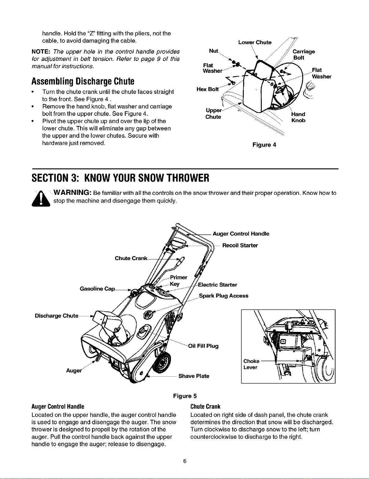
SECTION3: KNOWYOURSNOWTHROWER
4_ WARNING: Be familiar with all the controls on the snow thrower and their proper operation. Know how to
stop the machine and disengage them quickly.
Handle
Spark Plug Access
Auger _
_il Fill Plug
Shave Plate
Lever
Figure 5
AugerControlHandle
Located on the upper handle, the auger control handle
is used to engage and disengage the auger. The snow
thrower is designed to propell by the rotation of the
auger. Pull the control handle back against the upper
handle to engage the auger; release to disengage.
ChuteCrank
Located on right side of dash panel, the chute crank
determines the direction that snow will be discharged.
Turn clockwise to discharge snow to the left; turn
counterclockwise to discharge to the right.
Loading ...
Loading ...
Loading ...