
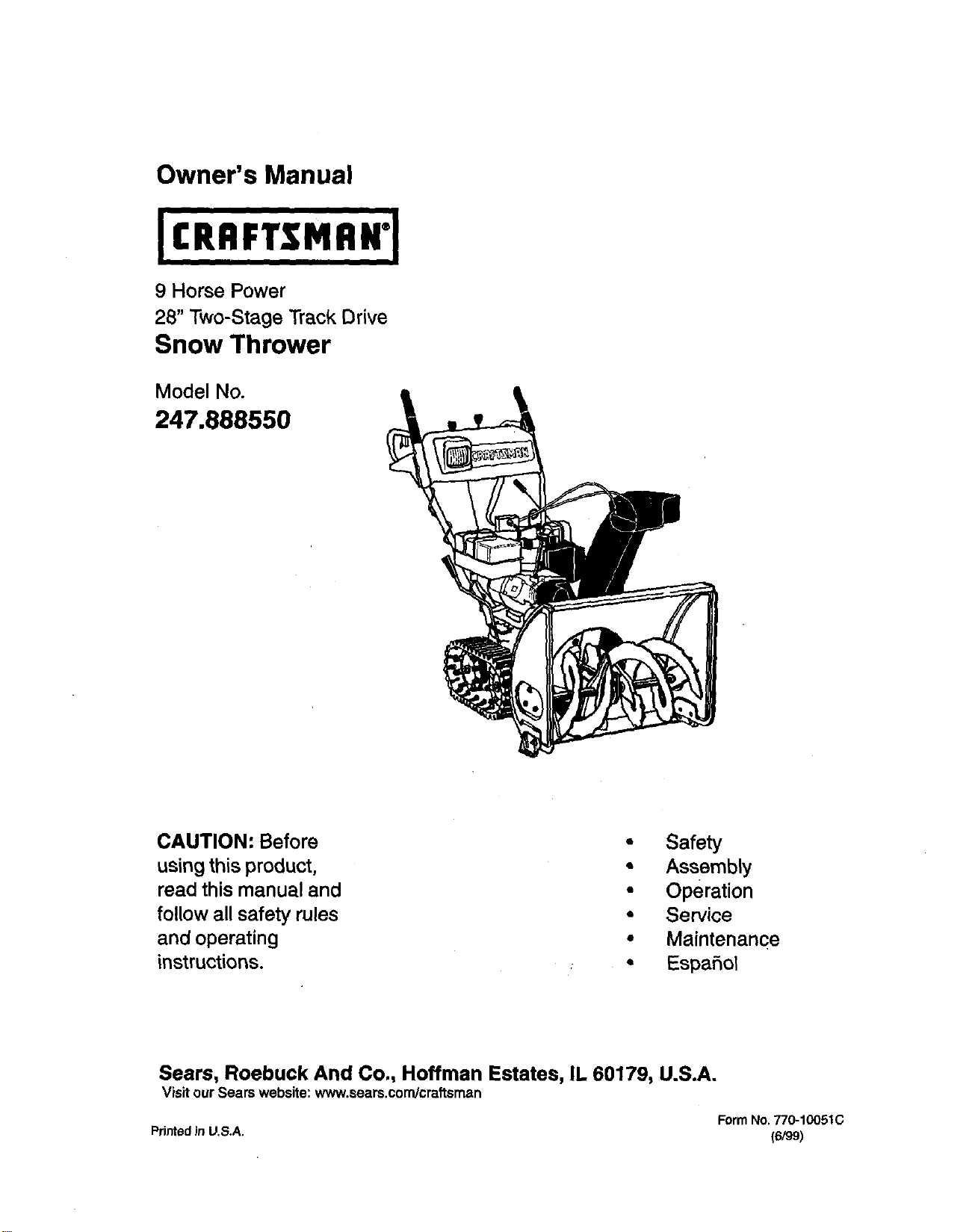
Owner's Manual
9 Horse Power
28" Two-Stage Track Drive
Snow Thrower
Model No.
247.888550
CAUTION: Before
usingthis product,
read this manual and
follow all safety rules
and operating
instructions.
• Safety
• Assembly
• Operation
• Service
• Maintenance
• Espafiol
Sears, Roebuck And Co., Hoffman Estates, IL 60179, U.S.A.
Visit ourSears website: www.sears.condcraftsman
FormNo.770-10051C
PdntedJnU.S.A. (6/99)
Content Page
Warranty Information......................................... 2
Safe OperationPractices................................... 3
Hardware Pack .................................................. 5
Assembly........................................................... 6
Operation............... ............................................ 12
Maintenance ...................................................... 17
Content Page
Service & Adjustment......................................... 20
Off*Season Storage........................................... 24
Trouble-Shooting............................................... 25
PartsList............................................................ 26
Espanbl.............................................................. 40
Two -Year Warranty on Craftsman Snow Thrower
Fortwoyearsfrom the date ofpurchase,when this CraftsmanSnow Throwerismaintained,lubricatedand tuned
up accordingto the instructionsinthe owner'smanual, Sears willrepair,free ofcharge, any defectin material
and workmanship.
Ifthis Craftsman snow throwerisused for commercial or rentalpurposes, thiswarrantyapplies for only30 days
from the date of purchase.
This warranty does not cover:
Expendable itemswhich become worn duringnormal use, suchas skidshoes, shave plate and spark
plugs.
Repairs nec•ssary because of operatorabuse or negligence,includingbent crankshaftsand the failure to
maintainthe equipmentaccordingto the instructionscontainedin theowner'smanual.
WARRANTY SERVICE ISAVAILABLEBYRETURNING THE CRAFTSMAN SNOWTHROWER TOTHE NEAREST
SEARS SERVICE CENTER/DEPARTMENT IN THE UNITED STATES.
This warranty applies only while this product Is In use in the United States.
Thiswarrantygivesyouspecificlegal rightsandyou mayalsohaveotherdghts whichmayvaryfrom statetostate.
SEARS,ROEBUCKAND CO., D/817WA,HOFFMAN ESTATES,IL60179
Horsepower: 9
EngineOil SAE 5W30 oil
FuelCapacity: 1 gallon
Spark Plug: RJ-19LM
Engine: 143.999005
Model Number 247.888550
Serial Number ...........................................................
Date of Purchase ......................................................
Record both serial number and date of purchase and
keep in a safe place for future reference.
This symbol points out important safety instructions which, ifnotfollowed, could endanger the
personalsafetyand/or propertyofyourselfand others. Read and followall instructions in this manual
beforeattemptingtooperate your snow thrower.Failure tocomplywiththese instructionsmay resultin
personal injury.When yousee thissymbol--heed its warning.
,_ Your snowthrower was builttobe operated accordingtothe rulesforsafe operation inthis manual. As
DANGER" withany type of powerequipment carelessness or erroron the partof the operatorcanresultin serious
in ury. f you vo ate anyof these rules,you may cause serious njurytoyourselfor others.
Thisunitisequippedwithaninternalcombustionengineandshouldnotbe usedonornearany unimproved
forest-covered, brush-coveredorgrass-coveredlandunlesstheengine'sexhaustsystemisequippedwitha
sparkarrestermeetingapplicablelocalorstate laws(ifany). Ifa sparkarresterisused,itshouldbe
maintainedineffectiveworkingorderbytheoperator.
In theStateofCaliforniathe aboveisrequiredbylaw(Section4442 ofthe CaliforniaPublicResources
Code).Otherstatesmayhavesimilarlaws.Federallawsapplyonfederal lands.Asparkarresterfor the
mufflerisavailablethroughyournearestSearsAuthorizedServiceCenter(See theREPAIR PARTSsection
ofthismanual.)
TRAINING
Read thisowner'sguide carefullyin itsentiretybefore
attemptingtoassemble oroperate this machine. Be
completelyfamiliar withthe controlsand the proper
useof this machinebefore operatingit. Keep this
manual ina safe placefor future and regular
reference andfor orderingreplacement parts.
Never allowchildrenunder 14 years oldto operate a
snowthrower.Children 14 years oldand over should
onlyoperate a snowthrower underclose parental
supervision.Onlypersonswell acquainted with these
rulesof safe operationshould be allowedto useyour
snowthrower.
No one should operate thisunitwhileintoxicated or
whiletaking medicationthat impairsthe senses or
reactions.
Keepthe area ofoperationclear of all persons,
especially smallchildrenand pets.
Exercise caution toavoidslippingor falling,especially
when operating inreverse.
PREPARATION
Thoroughlyinspectthe area where the equipmentis
to be usedand remove alldoor mats, sleds,boards,
wiresand other foreign objects.
Donot operate equipment withoutwearing adequate
outergarments for winter.Do notwear jewelry, long
scarfsor otherlooseclothingwhichcould become
entangled inmovingparts.Wear footwear whichwill
improvefootingon slipperysurfaces.
Before workingwithgasoline,extinguishalt cigarettes
and othersourcesof ignition.Check the fuel before
startingthe engine. Gasolineis an extremely
flammable fuel. Donot fillthe gasolinetank indoors,
while the engine isrunning,or untilengine has been
allowed to cool at least twominutes. Replace
gasolinecap securelyand wipe off any spilled
gasolinebefore startingthe engine as itmay cause a
fireor explosion.
Use a grounded threewire plug-infor all unitswith
electricdrive motors or electricstartingmotors.
Adjustcollector housingheightto clear gravelor
crushed rocksurface.
Never attemptto make any adjustmentswhile engine
is running(except where specificallyrecommended
by manufacturer).
Letengine and machineadjusttooutdoor
temperature beforestartingto clearsnow.
Always wear safety glasses oreye shields during
operationor whileperformingan adjustmentor repair,
to protecteyes from foreign objectsthat may be
thrownfrom the machinein any direction.
OPERATION
Do not put hands orfeet near or under rotatingparts.
Keep clearofdischargeopening and auger at all
times.
Exercise extremecaution when operatingon or
crossinggraveldrives, walks,or roads. Stay alert for
hidden hazardsor traffic.
Do not carry passengers.
Afterstrikinga foreign object,stopthe engine, remove
wire from the spark plugand thoroughlyinspectthe
snowthrower for any damage. Repair the damage
before restartingand operatingthe snowthrower.
Ifthe snowthrower startsto vibrate abnormally,stop
the engineand check immediatelyfor the cause.
Vibrationisgenerallya warningoftrouble.
Stopthe engine whenever you leave the operating
position,before uncloggingthe collector/impeller
housingor dischargeguide and before making any
repairs,adjustments,or inspections.Never place your
hand in the dischargeor collectoropenings.Use a
stickor woodenbroomhandle to unclogthe
discharge opening.
Take allpossible precautionswhen leavingthe unit
unattended. Disengage the collector/impeller,stop
the engine and removethe key.
When cleaning, repairing,or inspecting,make certain
collector/impellerand allmovingpartshave stopped.
Disconnectsparkplugwire and keep away from plug
to prevent accidentalstarting.
• Do not runthe engine indoors,exceptwhen startingit
and/ortransportingthe snowthrower in oroutof
building.Open doors beforestartingtheengine inthat
case. Exhaust fumes are dangerous.
Do not clearsnowacross theface ofslopes. Exercise
extreme caution when changing directionon slopes.
Do not attemptto clearsteep slopes.
Never operate the snowthrower withoutguards,
plates or othersafety protectiondevicesin place,
• Never operate the snowthrower near glass
enclosure, automobiles,windowwells, dropoff, etc.,
withoutproper adjustmentsofsnow thrower
dischargeangle. Keep childrenandpets away.
Do notoverload machine capacity by attemptingto
clear snow at toofast a rate. Never operate the
machine at hightransportspeeds onslippery
surfaces. Lookbehindand use care whenbacking.
Never direct dischargeat bystandersor allowanyone
in front of unitwhilethrowingsnow.
• Disengagepower tocollector/impellerofthe srx)w
throwerwhentransportingitorwhen the unitisnotin use.
Use only attachments and accessories(such as
wheel weights,counterweights, cabs, etc.)approved
by the snowthrower manufacturer.
Never operatethe snowthrowerwithoutgoodvisibility
or light.Always be sure ofyourfooting and keep afirm
holdonthe handles.Walk, never run.
Mufflerand engine become hotand can cause severe
bum injury.Do nottouchthe mufflerorthe engine
whilestarting oroperatingthe snowthrower.
MAINTENANCE AND STORAGE
Check shearbolts, enginemountingbolts,etc., at
frequent intervalsfor propertightness,thusensuring
thatthe equipment isinsafe workingcondition.
Never storethe machinewithfuel in the fuel tank
insidea buildingwhere ignitionscumes are present,
suchas hotwater heaters,space heaters, clothes
dryersand the like.Allowengineto cool beforestoring
in anyenclosure.
Alwaysrefer to owner'sguide instructionsfor
importantdetails ifthesnowthrower istobe storedfor
an extended period.
Runmachine a few minutesafterthrowingsnowto
preventfreeze-up ofthe collector/impeller.
Check clutchcontrolsperiodicallyto verifythat these
engage and disengageproperlyand readjust if
necessary. Referto Serviceand Adjustmentssection
page ofthis owner'sguide.
YOUR RESPONSIBILITY
Restrictthe useof this powermachineto personswho
read, understandand follow the warnings and
instructionsinthis manualand on the machine.
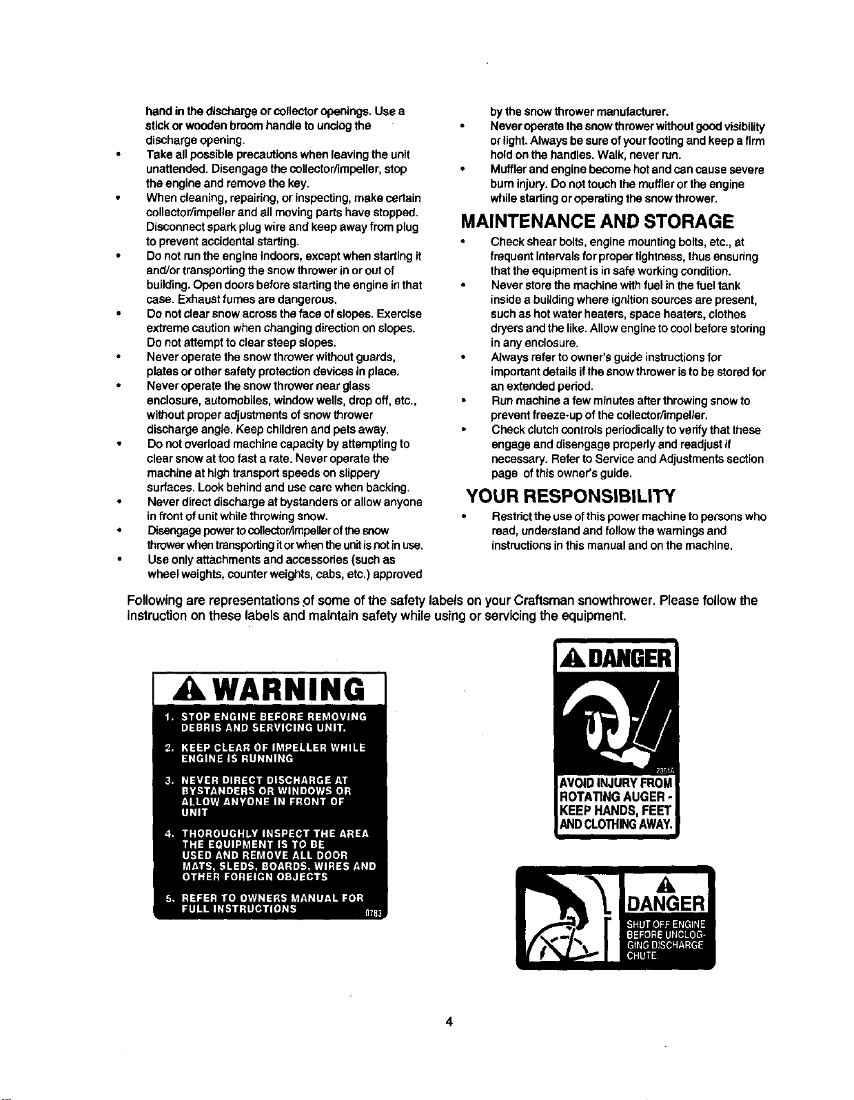
Following are representationsof some of thesafety labelson yourCraftsman snowthrower.Please follow the
instructionon these labels and maintain safety while usingor servicingthe equipment.
I ,A WARNING
ADANGER
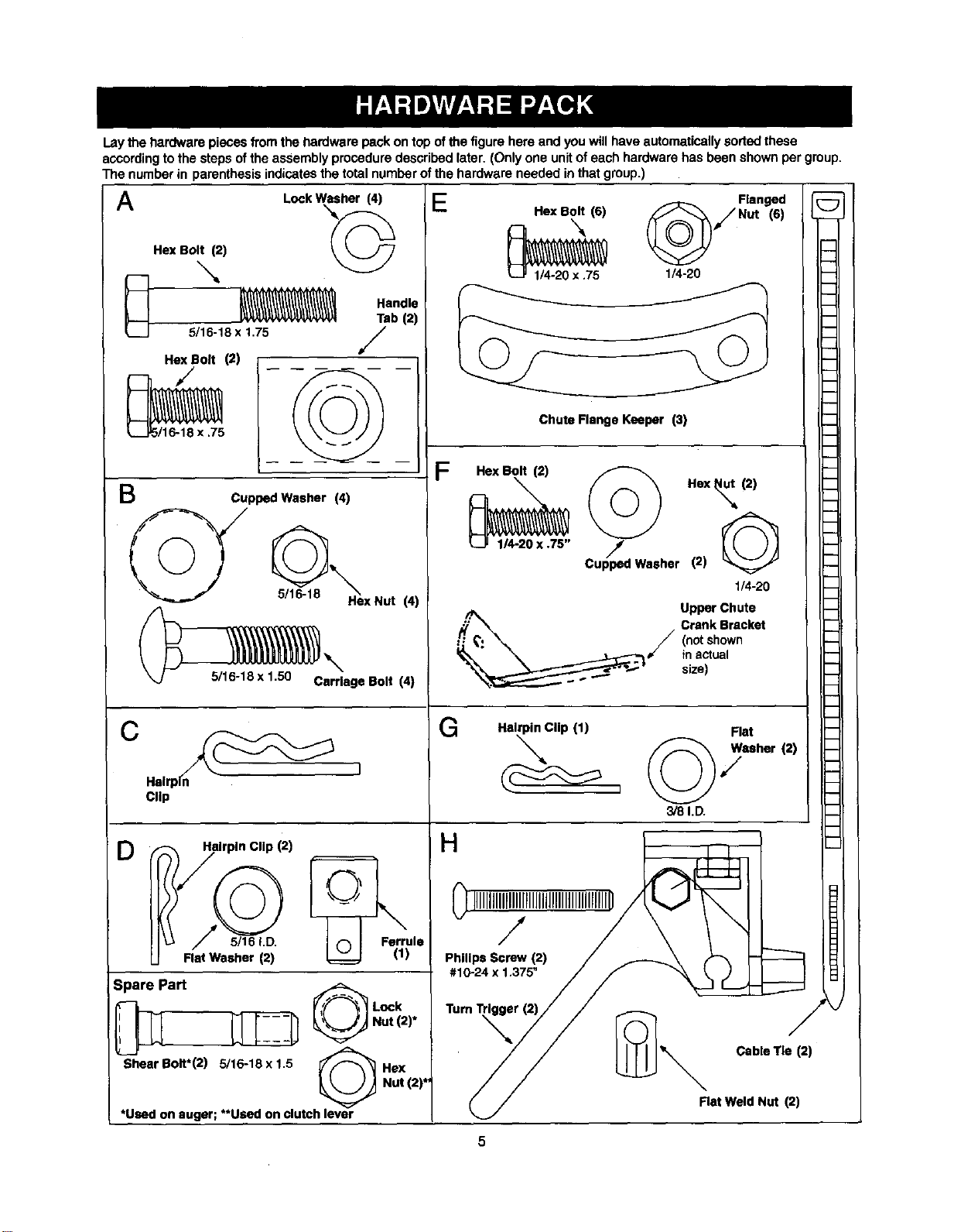
Lay the hardware pieces from the hardware pack on top of the figure here and you will have automatically soded these
aCCordingtothe steps ofthe assembly procedure described later. (Only one unitofeach hardware has been shown per group.
The number in parenthesis indicatesthe total numberofthe hardware needed in that group.)
q
m
h
A
B
LockWasher (4)
Hex Bolt (2) /_
5/16-18 x 1.75
Hex Bolt (2)
,/t
NN
5/16-18 x .75
Handle
Tab (2)
/
Cupped Washer (4)
HexNut (4)
_5/16-18 x 1,50 Carriage Bolt
_\ (4)
(_ Helrp_ ]
D
Clip
-_fi_ilrpln Clip (2)
I Ferrule
Flat Washer (2) _ ! (1)
3pare Part
"ShearBolt*(2) 5/16-18 x 1.5
Lock
Nut (2)*
Hex
Hot (2)*
*Used on auger; **Used on clutch lever
_/Flanged _;
E_ Hex Bolt (6) Nut (6)
- 'N "--"
1/4-20 x .75 1/4-20
Chute Flange Keeper (3)
F
:-_"exBolt(2) _) Hex_, (2)
1/4-20 X .75" Cup_ped Washer (2) G
1/4-20
Upper Chute
'_/ Crank Bracket
(notshown
inactual
size)
G
m
i
m
m
b
b
m
Hairpin Clip (1) Flat
©7
3/8 I.D.
H
HIIIIIIIIIIIIIIII_,@_ -
,1024x,375"/F "__
TurnTr_r_//// _" Cable Tie (2)_
//
_,/ Rat Weld Nut (2)
Chute
Handte
Panel
Handles
Rear
, Left
Chute
Crank
Shift
Rod
Electric
Start Cord
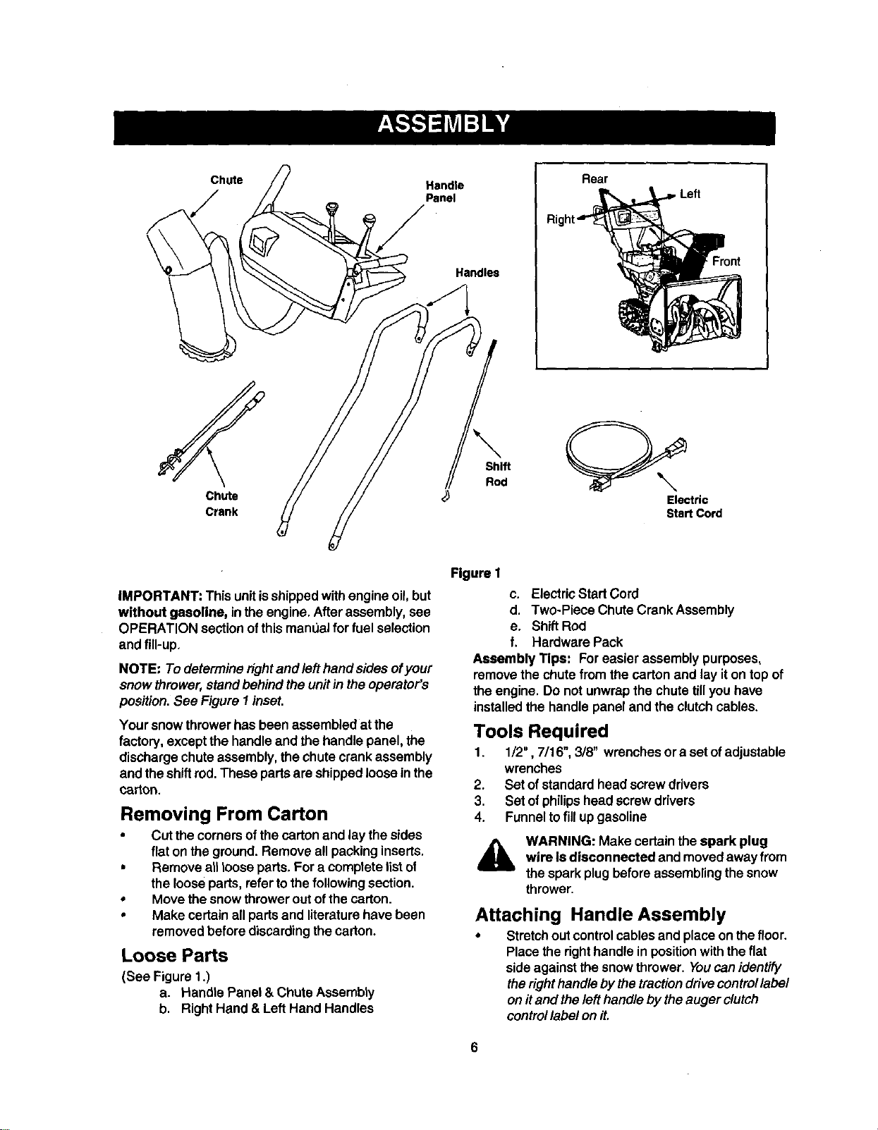
iMPORTANT: This unitisshippedwithengine oil, but
without gasoline, in the engine.Afterassembly, see
OPERATION sectionofthismanLJalfor fuel selection
and fill-up.
NOTE: To determineright and lefthand sides ofyour
snow thrower,standbehind the unitin the operator's
position.See Figure I inset,
Your snowthrowerhas been assembledat the
factory, exceptthe handle and thehandle panel, the
dischargechute assembly,the chute crank assembly
and the shiftrod.These partsare shippedlooseinthe
carton.
Removing From Carton
• Cut the comersof thecartonand lay thesides
fiaton theground.Remove all packinginserts.
• Remove all looseparts,For a completelistof
the looseparts, refertothe following section.
• Move thesnow throweroutofthe carton.
• Make certainall partsand literaturehave been
removedbefore discardingthecarton.
Loose Parts
(See Figure 1.)
a. Handle Panel & ChuteAssembly
b. Right Hand &Left Hand Handles
Figure I
c. ElectricStartCord
d. Two-Piece ChuteCrank Assembly
e. Shift Rod
f. Hardware Pack
Assembly Tips: Foreasier assembly purposes,
remove thechute from the carton and lay iton top of
the engine. Do not unwrapthe chute tillyou have
installedthe handle paneland the clutchcables.
Tools Required
1. 1/2", 7/16", 3/8" wrenchesor a set ofadjustable
wrenches
2. Set ofstandardhead screwdrivers
3. Set ofphilipshead screw drivers
4. Funneltofill up gasoline
WARNING: Make certainthe spark plug
wire Is disconnected and movedaway from
the spark plugbeforeassemblingthe snow
thrower.
Attaching Handle Assembly
• Stretchout controlcables and place on thefloor.
Placethe righthandle in positionwiththeflat
side againstthesnow thrower. Youcanidentify
the right handleby the traction drive control label
on it and the left handle by the auger clutch
control label on it.
6
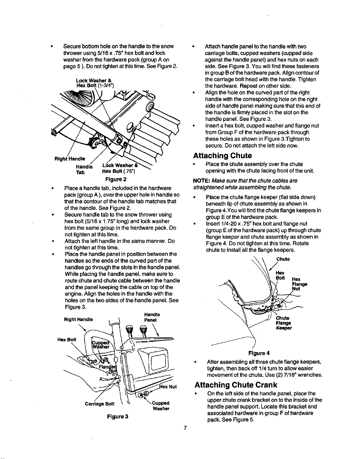
Securebottomholeonthehandletothesnow
throwerusing5/16x.75"hexboltandlock
washerfrom the hardware pack (groupA on
page 5 ). Donottightenatthistime.See Figure2.
Lock Washer &
He]( Bolt (1-3/4")
Right Handle
Handle
Tab Hex Bolt (.75")
Figure 2
• Place a handle tab, includedinthe hardware
pack (groupA ), overthe upperhole in handle so
thatthe contourofthe handle tab matchesthat
of thehandle. See Figure2.
• Secure handletab tothe snow throwerusing
hexbolt(5/16 x 1.75" long)and lockwasher
from the same groupinthe hardware pack. Do
nottightenat thistime.
• Attachthe lefthandle inthe same manner. Do
nottightenat this time.
• Placethe handle panelin positionbetween the
handles sothe ends ofthe curvedpart ofthe
handlesgo throughtheslotsinthe handlepanel.
While placingthehandle panel, make sure to
routechute andchute cable between the handle
and thepanel keepingthe cable on top ofthe
engine. Align the holesinthe handlewiththe
holesonthe two sides ofthe handlepanel. See
Figure3.
RightHandle 1
..xoo,t
/
Carriage Bolt
Handle
Panel
Washer
Figure 3
7
• Attachhandle paneltothe handle withtwo
carriagebolts,cupped washers (cuppedside
againstthe handle panel) and hex nutson each
side.See Figure3. You willfind these fasteners
ingroupBofthe hardware pack.Aligncontourof
thecarriage bolthead withthe handle.Tighten
thehardware. Repeat on otherside.
• Align the holeon thecurved partofthe right
handle withthecorrespondingholeon the right
side ofhandlepanel makingsure thatthisend of
the handle isfirmly placedinthe sloton the
handlepanel. See Figure3.
• Inserta hex bolt, cuppedwasher and flange nut
from Group F of the hardware pack through
these holes as shown in Figure 3.Tighten to
secure, Do notattach the left side now.
Attaching Chute
• Place thechute assemblyover thechute
openingwiththe chutefacing frontofthe unit.
NOTE: Make sure that thechute cables are
straightened while assemblingthechute.
Placethe chuteflange keeper (flat side down)
beneath lipofchute assembly as shownin
Figure 4.You will find the chute flange keepers in
group E of the hardware pack.
Insert 1/4-20 x .75" hex bolt and flange nut
(group Eof the hardware pack) up through chute
flange keeper and chute assembly asshown in
Figure 4. Do not tighten at this time. Rotate
chute to instal! all the flange keepers.
Figure 4
Afterassembling allthree chuteflange keepers,
tighten,then backoff 1/4turntoalloweasier
movementofthe chute.Use (2) 7/16" wrenches.
Attaching Chute Crank
• Onthe leftside ofthe handle panel, placethe
upperchute crankbracket ontothe insideofthe
handle panelsupport.Locate thisbracketand
associatedhardware ingroupF ofhardware
pack. See Figure5.
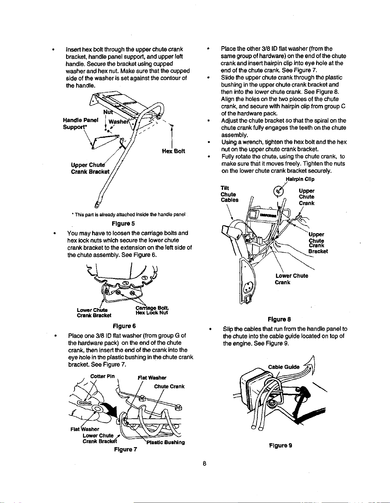
Inserthexboltthroughthe upper chutecrank
bracket,handle panelsupport,and upper left
handle.Secure thebracketusingcupped
washer and hex nut.Make surethat thecupped
side ofthewasher isset againstthe contourof
the handle.
Handle Panel l
Support*
\ "<
Hex Bolt
Crank Bracket
Placetheother3/8 ID flat washer (fromthe
same groupof hardware)on theend ofthechute
crank and inserthairpinclipintoeye holeat the
end ofthe chutecrank. See Figure7.
Slidethe upperchute crank throughtheplastic
bushinginthe upperchute crank bracketand
then intothe lowerchutecrank. See Figure8.
Alignthe holeson thetwo piecesofthe chute
crank,and securewith hairpinclipfrom groupC
ofthe hardwarepack.
Adjustthe chutebracketso thatthespiralon the
chutecrankfully engagesthe teeth onthe chute
assembly.
Using a wrench, tightenthe hex boltand the hex
nut onthe upperchutecrank bracket.
Fullyrotatethechute, usingthe chute crank, to
make surethat itmovesfreely.Tightenthe nuts
on the lowerchutecrank bracketsecurely.
* This part isalready attached inside the handle panel
Figure 5
You may have to loosenthe carriage boltsand
hex locknutswhichsecurethe lowerchute
crank brackettothe extensionon theleftside of
the chute assembly.See Figure6.
L rrlage Bolt,
CrankBracket ItexLockNut
Figure 6
Place one 3/8 ID flatwasher (fromgroupG of
the hardware pack) on theend ofthe chute
crank,then insertthe end ofthecrank intothe
eye holeinthe plasticbushinginthechute crank
bracket.See Figure7.
Cotter Pin
Flat Washer
Chute Crank
Tilt Upper
Chute Chute
Cables
Crank
\
Upper
Chute
Crank
Bracket
LowerChute
Crank
Flgure 8
Slipthecables thatrunfrom the handle panelto
thechute intothecable guidelocatedon topof
theengine. See Figure9.
Cable Guide
Flat Rasher
Lower Chute /
Crank Bracl_t
Figure 7
Figure 9
8
Tightenallloose hardware on the handle
assemblyin thefollowingorder-- firstthe hex
boltsat the bottomof the handle, then the
carriagebolts and lastlythe hex boltson the rear
ofthe handle panel.
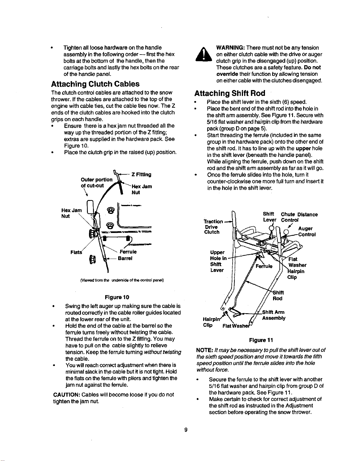
Attaching Clutch Cables
The clutchcontrolcables are attachedto the snow
thrower.Ifthe cables ere attachedto the top ofthe
engine withcable ties, cutthecable tiesnow.The Z
ends of theclutchcables are hooked intothe clutch
gripson each handle.
• Ensure there isa hexjam nutthreaded allthe
way upthe threaded portion ofthe Z fitting;
extras are supplied in the hardware pack. See
Figure 10.
• Place the clutch grip in the raised (up) position.
Z Fitting
Outer
ofcut-out
\ Nut
HexJam
Nut
A
WARNING: There mustnotbe any tension
on eitherclutchcable withthe driveor auger
clutchgripinthe disengaged (up) position.
These clutchesare a safety feature. Do not
override theirfunction by allowingtension
on eithercablewiththeclutchesdisengaged.
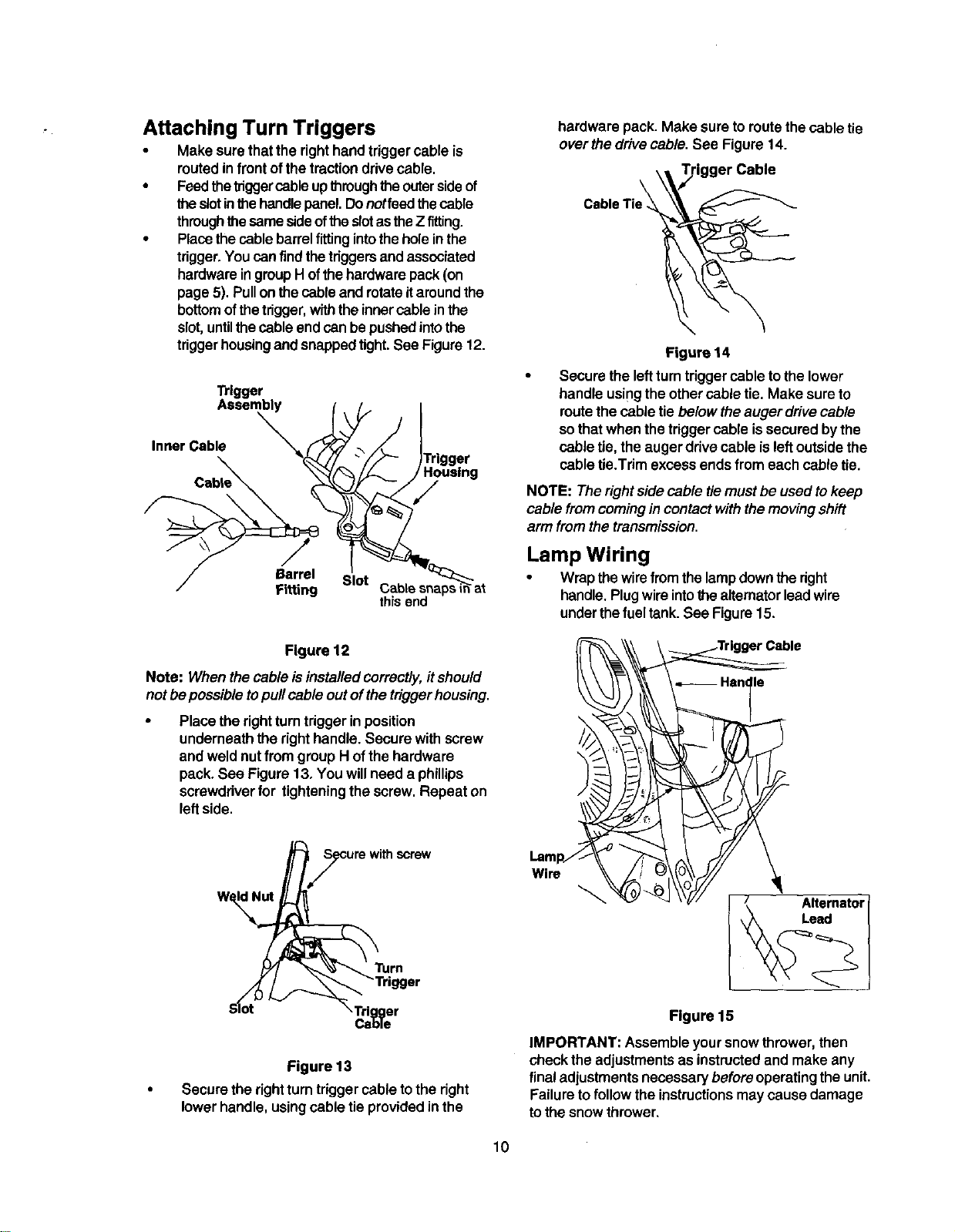
Attaching Shift Rod
• Placethe shiftlever inthesixth(6) speed.
• Placethebentendoftheshiftrodintotheholein
theshiftarmassembly.See Figuret 1.Securewith
5/16 flatwasherandhairpinclipfromthe hardware
pack(groupDon page 5).
• Startthreadingthe ferrule(includedinthe same
groupinthehardware pack)ontothe otherendof
the shiftrod. Ithas tolineup withthe upper hole
inthe shiftlever(beneath thehandle panel).
While aligningtheferrule,pushdownon theshift
rodand theshiftarmassemblyas far as itwillgo.
• Once theferrule slidesintothe hole, turnit
counter-clockwiseone more ful!turnand insertit
inthe holeinthe shiftlever.
Shift Chute Distance
Lever Control
Drive Auger
Clutch
Ferrule
Barrel
(Viewed from the underside of the controlpanel)
Upper
Shift
Lever
Clip
Figure 10
• Swingtheleftauger upmaking surethe cable is
routed correctlyin thecable rollerguideslocated
at thelower rear ofthe unit.
• Hold theend ofthe cable at the barrel sothe
ferrule turnsfreely withouttwistingthecable.
Thread theferrule on totheZ fitting.You may
have topullon the cable slightlyto relieve
tension.Keeptheferrule turningwithout twisting
thecable.
• You willreachcorrectadjustmentwhenthere is
minimalslackinthecable butitisnottight.Hold
theflats on theferrule withpliersandtightenthe
jam nutagainsttheferrule.
CAUTION: Cables willbecome looseifyoudo not
tighten thejam nut.
Rod
Clip
Assembly
Figure 11
NOTE: Itmay be necessary topull theshiftlever outof
thesixthspeed positionand moveit towardsthe fifth
speedpositio n untiltheferruleslidesintothehole
withoutforce.
Secure theferrule tothe shift leverwithanother
5/16 flatwasher and hairpin clipfrom group D of
the hardware pack. See Figure 11.
Make certain tocheckfor correctadjustmentof
the shiftrodas instructedintheAdjustment
sectionbeforeoperatingthesnow thrower.
9
Attaching Turn Triggers
Make surethatthe righthandtriggercable is
routedinfrontofthetractiondrivecable.
• Feedthetriggercableupthroughthe outersideof
theslotinthe handlepanel.Donotfeedthecable
throughthesamesideoftheslotastheZ fitting.
• Placethecablebarrelfitting intothe holeinthe
trigger.You canfindthetriggersandassociated
hardwareingroupHofthehardwarepack(on
page5). Pullonthe cable and rotateitaroundthe
bottomofthetrigger,withtheinnercable inthe
slot,untilthecable endcan bepushedintothe
triggerhousingand snappedtight.See Figure12.
Trigger
Assembly
Inner Cable
Y
Barrel Slot
Fitting
thisend
Figure 12
Note: When the cable isinstalled correctly, itshould
not be possibletopullcable out ofthe trigger housing.
Place the rightturntriggerinposition
underneaththe righthandle.Secure withscrew
and weld nutfrom group Hof thehardware
pack. See Figure 13. You willneed a phillips
screwdriverfor tighteningthe screw. Repeat on
leftside.
Turn
S_ot ,Trigger
Cable
Figure 13
• Secure therightturntriggercable tothe right
lowerhandle, usingcable tieprovidedinthe
hardware pack. Make sure to routethecable tie
over thedrivecable. See Figure 14.
Figure 14
Secure the leftturntriggercable to the lower
handle usingthe othercable tie. Make sureto
route the cable tie below the auger drive cable
sothat when the trigger cable is securedby the
cable tie, the auger drive cable is left outside the
cable tie.Trim excess ends from eachcable tie.
NOTE: The right sidecable tiemust be used tokeep
cable from comingin contact withthemoving shift
armfromthe transmission.
Lamp Wiring
• Wrapthewirefrom thelampdownthe right
handle.Plugwireintothe aitemator leadwire
underthefuel tank. See Figure15.
I _ Hsn le
Figure 15
IMPORTANT: Assembleyoursnowthrower, then
checkthe adjustmentsas instructedand make any
final adjustmentsnecessarybeforeoperatingthe unit.
Failureto follow the instructionsmaycause damage
tothe snowthrower.
10
Final Adjustments
Adjusting Auger Control
• To checktheadjustment ofthe auger control,
pushforward the lefthandclutchgrip untilthe
rubberbumper iscompressed,There shouldbe
slackinthe clutchcable.
• Release the clutchgrip.The cable shouldbe
straight. Make certain you can depress the
auger controlgripagainst the lefthandle
completely.
• If adjustmentisnecessary,loosen the hexjam
nutand thread thecable in(for lessslack)or out
(for more slack),
• Recheck theadjustment.Tightenthejam nut
againstthe cablewhen correctadjustmentis
reached.
Adjusting Traction Drive Control
To checkthe adjustmentofthetractiondrive
controland shiftlever,move theweighttransfer
levertothe transportposition(shownin Figure
18 on page 13) and theshiftlever allthe way
forward tosixth(6) position.
• Withthe tractiondrivecontrolreleased, pullthe
triggersuptothe handleand then pushthesnow
throwerforward to checkthatthe tracksturn.
• Squeeze tractiondrivecontrolagainstthehandle
and pullthestarter.The tracksshouldturn.
• Now release the tractiondrivecontroland pull
the starteragain. The unitshouldnot move.
• Beforeproceedingwith adjustment,make sure
thatthe spark plug is disconnected.
• Ifthetractiondrivecontrolneeds adjustment,
loosen thejam nut on thetractiondrivecable
and threadthe cable one turn. Recheck
adjustmentand repeat as necessary.
• Tightenthejam nuttosecure thecable when
correctadjustment isreached.
NOTE: Cables are outofadjustmentifaugers
continuetoturnwhenauger clutchisreleasedand/or
machine continuestorunwhen driveclutchis
released. For more details,refer totheService and
Adjustmentsection.
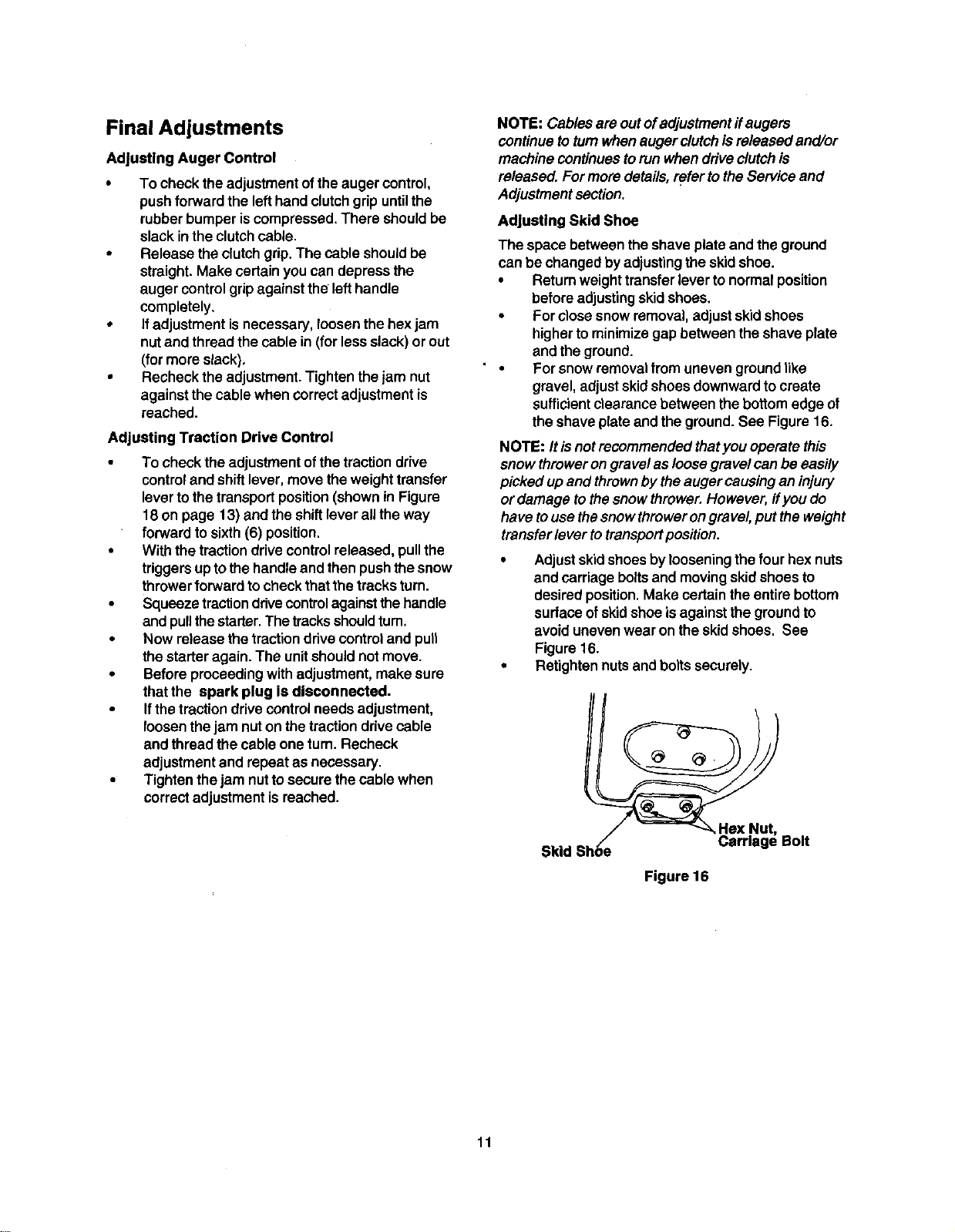
Adjusting Skid Shoe
The spacebetween the shaveplate and theground
canbe changed byadjustingthe skidshoe.
• Returnweighttransferlever to normalposition
before adjustingskidshoes.
• For closesnow removal,adjustskidshoes
higher to minimizegap between the shaveplate
and the ground.
• For snow removalfrom uneven groundlike
gravel, adjustskidshoes downwardtocreate
sufficientclearancebetween the bottomedge of
the shaveplate andthe ground.See Figure16.
NOTE: Itisnot recommendedthat you operate this
snow throweron gravelas loosegravelcan be easily
pickedup and thrownby theauger causingan injury
or damage tothesnowthrower.However, ifyou do
have tousethesnow throwerongravel,put the weight
transfer lever to transport position.
• Adjustskidshoesby loosening the four hex nuts
and carriage bolts and moving skidshoes to
desired position. Make certain the entire bottom
surface of skidshoe is against the ground to
avoid unevenwear on the skid shoes. See
Figure 16.
• Retightennuts and bolts securely.
Skid Shoe_ _HeXNa_t" Bolt
Figure 16
11
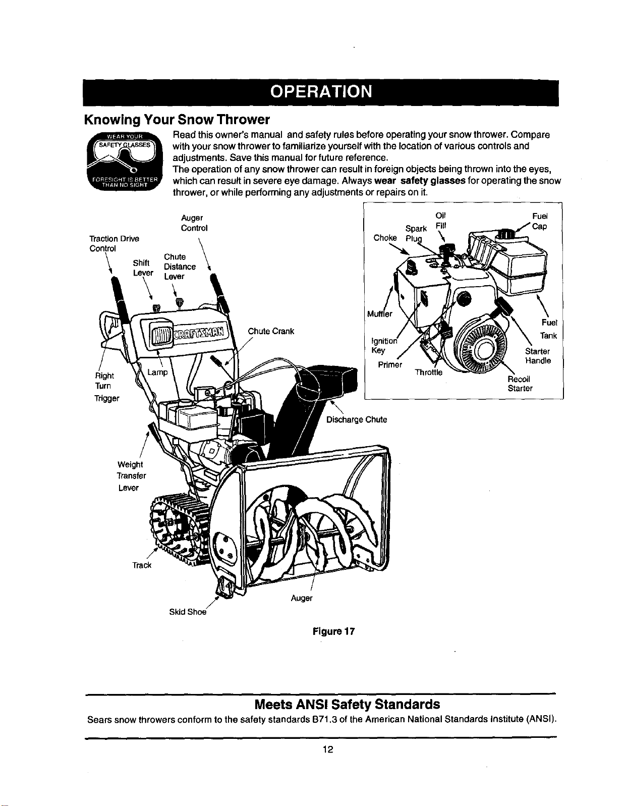
Knowing Your Snow Thrower
Read thisowner's manual and safety rules before operatingyoursnowthrower.Compare
withyoursnowthrowerto familiarize yourselfwiththe location ofvariouscontrols and
adjustments.Save this manualfor future reference.
The operationof anysnow throwercan resultin foreign objectsbeing thrownintothe eyes,
whichcan resultinsevere eye damage. Alwayswear safety glasses for operating the snow
thrower,or whileperforminganyadjustmentsor repairson it.
Auger
Control
Traction Drive
Control
Chute
Shift Distance
Lever Lever
Choke
Oil
Spark Fill
\
Fuel
Right
Turn
Trigger
Chute Crank
DischargeChute
Throttle
Fuel
Tank
Starter
Handle
Recoil
Starter
Weight
Transfer
Lever
Track
Skid Shoe
Auger
Figure 17
Meets ANSI Safety Standards
Sears snowthrowersconformtothe safety standardsB71,3 ofthe AmericanNationalStandardsInstitute(ANSI),
12
Operating Controls
(See Figure 17.)
Chute Crank
The chute crankislocated on the left sideof thesnow
thrower. To change the direction in which snow is
thrown, turn chute crank as follows:
turn clockwise to discharge to the left;
turn counterclockwiseto discharge to the right.
Chute Distance Control
The distance that snow isthrown can be adjusted by
adjusting the angle of the chute assembly. Push the
chute distance control lever forward to move the
upper chute down and decrease the distance. Pull the
lever back toward the rear to move the upper chute
up and increase the distance.
Left And Right Turn Trigger
The leftand rightturntriggers are located onthe
undersideofthe handles and are used toassistin
steeringyoursnow thrower.Squeeze the rightturn
triggerwhenturningright,squeeze theleftturntrigger
when turningleft. Operate yoursnowthrower inopen
areas untilyou become familiar withthesecontrols.
Shift Lever
The shift lever islocated inthe center ofthe handle
panel. It may be moved into one of eight positions:
a. Forward--oneofsixspoeds;po,v_onone(1)
isthe slowest and position six (6) isthe
fastest.
b. Reverse--two reverse (R) speeds; R2 is
faster.
Use the shift lever to determine ground speed. Do not
shiftto different speed while the unit is moving.
Auger Control
The auger controlis locatedon the left handle.
Squeeze the auger controlagainstthe handle to
engage theaugers; release todisengagethe augers.
(Tractiondrivecontrolmustalso be released.)
Traction Drive Control
The tractiondrive controlislocatedonthe right
handle. Squeeze the tractiondrive controltoengage
thetrackdrive;release to stop.
This same lever also locks the auger control so
thatyou canturn the chutecrank withoutinterrupting
the snowthrowingprocess.Ifthe augercontrolis
engaged withthetractiondrivecontrolengaged, you
can release the auger control(onthe lefthandle) and
the augers willremainengaged. Release the traction
drivecontrolto stopboththeaugers andthe track
drive. (Auger controlmustalsobe released).
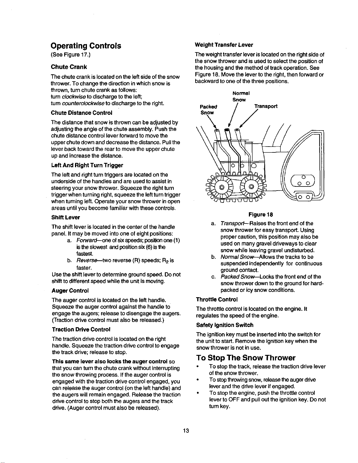
Weight Transfer Lever
The weighttransferlever islocatedonthe rightside of
thesnow throwerand isused toselectthe positionof
the housingand the methodoftrack operation.See
Figure 18. Move the lever tothe right,then forward or
backwardtoone ofthe three positions.
Packed
Snow
\
Normal
Snow
Transport
,/
Figure 18
a. Transport--Raises the front end of the
snowthrowerfor easytransport. Using
propercaution,thispositionmay also be
used on manygraveldrivewaysto clear
snowwhileleaving gravelundisturbed.
b. Normal Snow--Allows thetracksto be
suspendedindependently for continuous
groundcontact.
c. Packed Snow.--Locksthe frontend ofthe
snowthrowerdowntothe groundforhard-
packed or icysnow conditions.
Throttle Control
The throttlecontrolislocatedonthe engine. It
regulatesthe speed ofthe engine.
Safety Ignition Switch
The ignitionkey must be insertedintothe switchfor
the unitto start. Remove the ignitionkey when the
snow thrower is not in use.
To Stop The Snow Thrower
• To stopthetrack, release thetractiondrivelever
ofthe snowthrower.
• To stopthrowingsnow,releasetheaugerdrive
leverand the driveleverifengaged.
• To stopthe engine, pushthethrottlecontrol
leverto OFF and pulloutthe ignitionkey. Do not
turnkey.
13
Before Starting Engine
Fill Gas
&
WARNING: Gasolineisflammableand cau-
tionmustbe usedwhenhandling orstoringit.
Do notfillfuel tankwhilethe snowthroweris
running,when it ishotor when itisin an
enclosedarea.
Keep yoursnowthrower away from any
open flame or an electricalspark and do not
smoke while filling the fuel tank.
Never fill thefuel tank completely. Fill the
tankto within1/4"-1/2" from the topto
provide space for expansion of fuel.
Always fill the fuel tankoutdoorsand use a
funnel or spoutto prevent spilling.
Make sure towipeoffany spilledfuel before
startingthe engine.
• Store gasoline in a clean, approved container
and keep the cap in place on the container.
• Make sure that the container from which you
pour the gasoline is clean and free from rust or
other foreign particles.
• Fill fuel tank with clean, fresh, unleaded grade
automotivegasoline.
• At the end of the job, empty the fuel tank ifthe
snow thrower is notgoing to be used for 30 days
or longer. See storage instructions on page 24
of this manual.
CAUTION: Experience indicatesthat alcohol
blended fuels (calledgasohol)or those usingetha-
nolor methanol canattractmoisturewhich leads to
separationand formationofacids duringstorage.
Acidicgas can damage the fuel system ofan engine
whilein storage.
To avoidengineproblems,thefuel systemshouldbe
emptiedbeforestoragefor30 days orlonger. Drainthe
gastank,starttheengineand letitrununtilthefuel
linesand carburetor are empty.Use fresh fuel nextsea-
son.See storageInstructionsfor additionalinformation.
Never use engine or carburetor cleaner products in
the fuel tankor permanent damage may occur.
To Start Engine
&
WARNING: Be sure no one other than
the operator isstandingnear thesnow
throwerwhilestartingoroperating.Do not
operate thissnowthrowerunlessthe
dischargechuteassembly hasbeen
properlyinstalledand issecured.
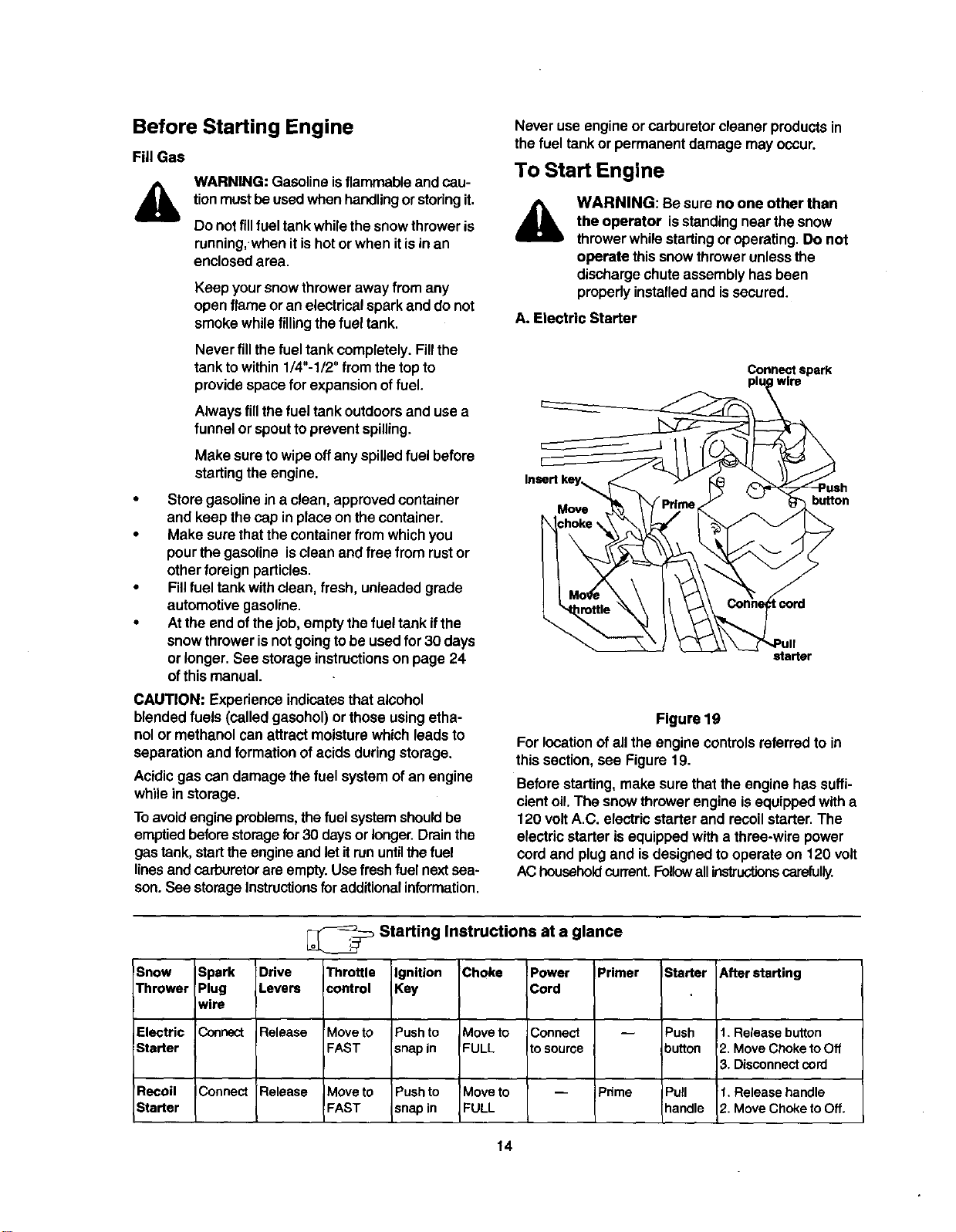
A. Electric Starter
Connect spark
wire
Insertkey_
Move
button
starter
Figure 19
Forlocationof allthe engine controlsreferredto in
this section,see Figure 19.
Before starting,make sure thatthe engine has suffi-
cient oil.The snow thrower engine isequippedwith a
120 voltA.C. electricstarterand recoilstarter.The
electricstarter is equippedwith a three-wire power
cordand plugand isdesignedtooperate on 120 volt
AC householdcurrent,Foll_vallinstructionscarefully.
!Snow Spark Drive
Thrower Plug Levers
wire
Electric Connect Release
Starter
Recoil IConnect Release
Starter
_ Starting Instructions at a glance
Throttle
control
Move to
FAST
Moveto
FAST
Ignition
Key
Pushto
snap in
Pushto
snapin
Choke
Move to
FULL
Move to
FULL
Power
Cord
Connect
tosource
Primer
Pnme
Starter After starting
Push t. Release button
button 2. Move Choke to Off
3. Disconnectcord
IPull t. Release handle
handle 2. Move Choke to Off.
14
ColdStart
NOTE:ff theunit shows anysignofmotion (driveor
augers) with the clutch grips disengaged,shutthe
engineoffimmediately. Readjustas instructedin the
"FinalAdjustments"sectiononpage 11.
WARNING: The electric starter mustbe properly
groundedat all timesto avoidpossibility ofelectric
shockwhichmay injurethe operator.
• Determinewhetheryourhousewiringisa three-
wire groundedsystem.Ask a licensed
electricianifyou are notcertain.
,_ WARNING: Ifyourhousewiringsystemis
not a three-wiregrounded system,do notuse
thiselectricstarterunderanyconditions.
• If yourhouse wiringsystem isgrounded and a
thrae-hole receptacle isnotavailableat the point
the snow thrower starter will normallybe used,
one should be installed by a licensed electrician.
• When connecting the power cord, always
connect cord to starter on engine first, then the
other end into a three-hole grounded receptacle.
• When disconnecting the power cord, always
unplug the end from the three-hole, grounded
receptacle first.
• Attach spark plugwire tospark plug.
• Make sure thatthe augerdriveand the traction
drivelevers are inthe disengaged RELEASED
position.
• Move throttlecontrolleverto FAST position.
• Removethe keysfrom the plasticbag. Push key
intothe ignitionslot.Make sure itsnaps into
place. Do not tumkey. Save thesecond key.
• Rotatethe choke knobto FULL choke position.
• Connect powercord to switchbox on engine.
• Plugthe otherend ofthe powercordintoa
three-hole, grounded120 voltA.C. receptacle.
WARNING: Do not use primerwhile
startingthe enginewith an electricstarter,
Push downonthe starterbutton untilthe engine
starts.Do notcrank formorethan 10 secondsat
a time. Thiselectricstarteristhermally
protected.Ifoverheated, itwillstop
automaticallyand can be restartedonlywhen it
has cooled to a safe temperature (a waitof
about5 to 10 minutes is required).
When the engine starts,release the starter
button and slowlyrotate the choke to OFF
position. If the enginefalters, rotate the choke to
FULL and then gradually to OFF.
Disconnect the power cord from the receptacle
first and then from the switch box on the engine.
Allow the engine to warm up for a few minutes
because the engine will not develop full power
until it reaches operating temperature.
Operate the engine at full throttle(FAST) when
throwing snow.
Warm Start
If restarting a warm engine after a shutdown,
rotatechoketo OFF insteadof FULL and press
the starter button.
B. Recoil Starter
Make sure that the engine has sufficientoil and the
auger drive and the traction drive levers are released.
• Move throttle control to FAST position.
• Push key into the ignitionslot so that it snaps
into place. Do not turn key. Remove plastic bag
and keep the second key in a safe place.
• Rotate choke control to FULL choke position.
• Pushthe primer button while covering the vent
hole.Removeyourfingerfromtheprimerbetween
primes.Do not primeiftemperature isabove
50° F; primetwo timesbe{ween50° F and 15oF;
andprimefourtimesbelow15° F.
• Pullthe starterhandle rapidly.Do not allowthe
handletosnap back, butallowitto rewindslowly
whilekeepinga firmholdon the starterhandle.
• As the engine warmsup and beginsto operate
evenly, rotatethechoke knobslowlyto OFF
position.Ifthe engine falters, returnto FULL
choke, thenslowlymovetoOFF chokeposition.
• Allow the engine towarm upfor a few minutes
becausethe engine willnotdevelop fullpower
untilitreaches operatingtemperature.
• Operate the eng!neat fullthrottle(FAST) when
throwingsnow.
Warm Start
• If restartinga warmengine after a temporary
shutdown, rotatechoke toOFF insteadof FULL
and do notprime. Pressthe starterbutton.
Frozen Recoil Starter
If the starter isfrozen and willnot turnthe engine,
proceed as follows:
• Pull as much rope out of the starter as possible.
• Release the starter handle and let it snap back
against the starter.
• If the engine still fails to start, repeat the first two
steps. If continued attempts do not free starter,
follow the electric starter procedures to start.
• Avoid possible freezing of recoil starter and the
engine controls.
Operating Snow Thrower
To Engage Drive
With the engine running near top speed, move
shift lever toone of sixFORWARD positions or
two REVERSE positions.Select a speed
appropriatefor thesnowconditionsthat exist.
15
Use slowerspeeds untilyou are familiar withthe
operationofthe snowthrower.
Squeeze the tractiondriveclutchgrip againstthe
righthandle and the snowthrowerwillmove.
Release itand the drivemotionwillstop.
To Engage Augers
To engage augers and start snowthrowing,
squeeze theleft handauger clutchgrip against
the lefthandle. Release tostop augers.
While the augercontrolisengaged,squeeze the
tractiondrivecontroltomove, releaseto stop. Do
not shiftspeeds whilethe driveisengaged.
NOTE: This same lever also locksthe auger control so
you can turnthe chute crank without interrupting the
snow throwing process.
• Release the auger control;the interlock
mechanismshouldkeepthe auger control
engaged untilthe tractiondrive controlis
released.
• Release thetractiondrivecontroltostopboth the
augersand the trackdrive.
,_ WARNING: To stoptheauger, both levers
mustbe released.
To Throw Snow
CAUTION: Check the area to be clearedfor foreign
objects. Remove, ifany.
• Move weighttransfer levertothe right, then
backward or forward tothe desired position.
• Startthe enginefollowing StartingInstructions.
Rotate thedischargechuteto thedesired
direction,away from bystandersand/orbuildings.
Move thechute distancecontrolforward or
backwardto adjustthedistancethe snowisto be
thrown.
• Selectthe speed accordingtothe snow
condition.
CAUTION: Never movethe shiftlever withoutfirst
releasingthe driveclutch.
Engagethe auger controland tractiondrive
controllevers following the preceding
instructions.
The interlock feature willallow youto remove
yourlefthandfrom theauger controllever.
When clearingthe first passthroughthe snow,
controlthe tractionspeed ofthe snowthrower
accordingtothe depthand conditionofsnow.
To turnthe unitleft, squeeze lefttrigger;toturn
right,squeeze righttrigger.
On each succeedingpass, readjustthechute
deflectortothedesired positionand slightly
overlapthe previouslycleared path.
• Afterthearea iscleared, stopthe snowthrower
following instructionsgivenbelow.
Operating Tips
NOTE: AIIowthe engineto warmup fora few minutes
as theengine willnot developfullpower untilff
reaches operatingtemperature.
Warning: The temperature ofmufflerand
surroundingareas mayexceed 150° F. Avoid
theseareas.
• Formost efficientsnow removal, removesnow
immediatelyafter itfalls.
• Discharge snowdownwindwhenever possible.
Slightlyoverlapeach previousswath,
• Settheskidshoes1/4"belewthescraperbarfor
normalusage.The skidshoesmaybe adjusted
upwardfor hard-packedsnow.Adjustskidshoes
downwardwhen usingon gravel orcrushedrock.
• Cleanthesnowthrower thoroughly aftereachuse.
Before Stopping
• Run enginefor a few minutesto helpdry offany
moistureon engine.
To avoidpossible freeze.up ofthe starter, follow
these steps:
Recoil Starter
a. Withtheengine running,pullthe starterrope
witha rapid,continuousfullarmstrokethree
or fourtimes.
Electric Starter
a. Connect powercordtoswitchbox,thento
120 Volt AC receptacle.
b. While the engineis running,pushthestarter
buttonand spinthe starterforseveral
seconds.
c. Disconnectpowercord from the receptacle
first,then fromthe snowthrower.
NOTE: The unusual sound from pulling thestarter
rope in thecase oftherecoilstarter,orfromspinning
thestarterin the case ofthe electricstarter,willnot
harm theengine.
To Stop The Snow Thrower
• To stopthetrack, release the tractiondrivelever
on thesnow thrower.
• Tostopthrowing snow,releaseaugerdrivelever
and drivelever, ifengaged.
• To stopthe engine,pushthrottlecontrolleverto
OFF and pulloutthe ignitionkey. Do not turnkey.
16
General Recommendations
Always observesafety rules when performing
anymaintenance.
The warrantyon thissnow throwerdoes not
cover itemsthat have been subjectedto
operatorabuse ornegligence.To receive full
value from thewarranty, operatormustmaintain
the snow throweras instructedinthis manual.
Some adjustmentswillhaveto be made
periodicallyto maintainyourunitproperly.
• All adjustments inthe Service and Adjustments
sectionofthis manualshouldbe checked at
least once each season.
• Follow the maintenanceschedule given below.
Periodically check all fasteners and make sure
these are tight.
&
WARNING: Alwaysstop the engine and
disconnect the sparkplug wirebefore
performingany maintenanceor
adjustments.
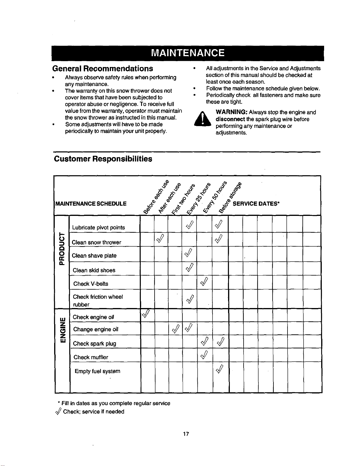
Customer Responsibilities
MAINTENANCE SCHEDULE ._oJ _ _ _ • _ __o_ SERVICE DATES*
Lubricatepivotpoints <_
Clean snowthrower
0 Clean shave plate
a.
Clean skid shoes '_
Check V-belts
Check friction wheel
rubber
Check engine oil '_
_Z Change engine oil _:_ <_
I
Z
g.l Check spark plug '_
Check muffler
Emptyfuel system '_
* Fill in dates as you complete regular service
Check; service ifneeded
17
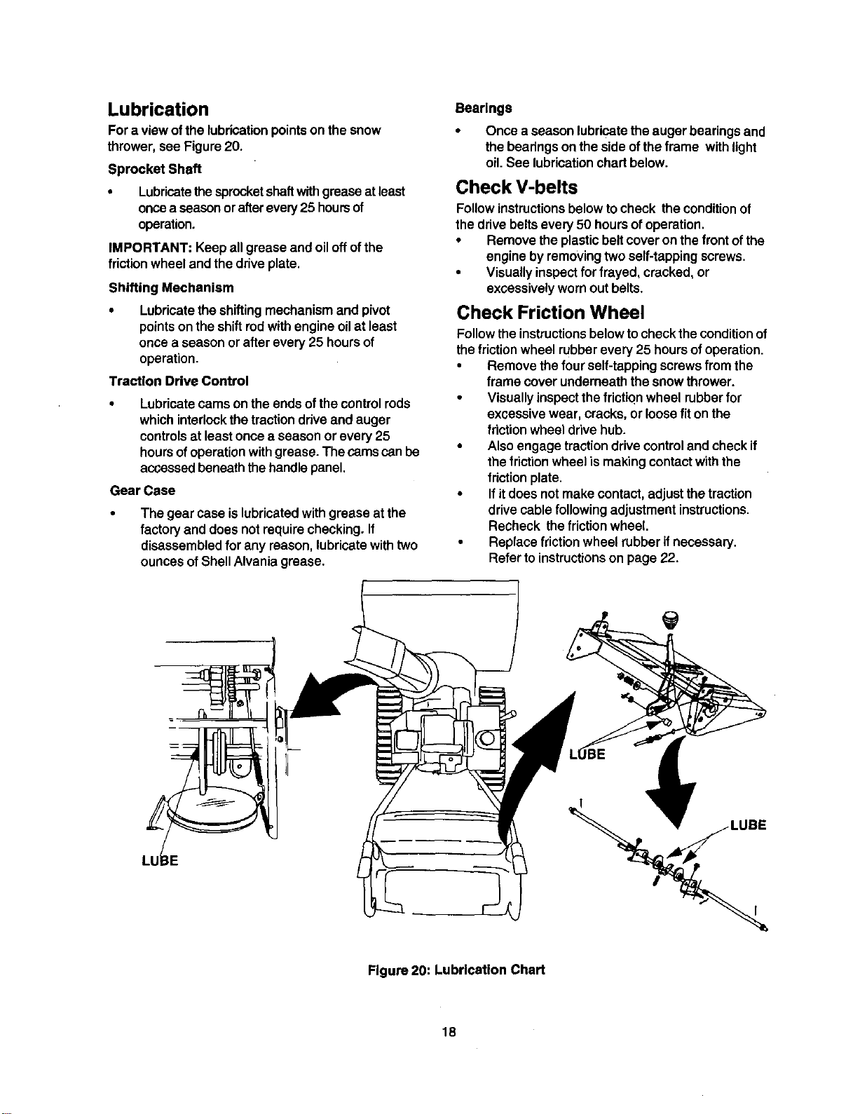
Lubrication
Fora view ofthe lubricationpointson thesnow
thrower,see Figure20.
Sprocket Shaft
• Lubricatethesprocketshaftwithgreaseat least
oncea seasonorafterevery25 hoursof
operation.
IMPORTANT: Keepall grease and oiloffofthe
friction wheel andthe driveplate.
Shifting Mechanism
• Lubricatetheshiftingmechanismand pivot
pointsonthe shiftrodwith engine oilat least
once a season or afterevery 25 hoursof
operation,
Traction Drive Control
• Lubricate cams onthe ends ofthe controlrods
whichinterlockthe tractiondriveand auger
controlsat leastoncea season or every 25
hoursofoperationwithgrease. The camscanbe
accessedbeneaththehandlepanel,
Gear Case
The gear case islubricatedwithgrease at the
factory and does notrequirechecking.If
disassembledfor any reason, lubricatewithtwo
ouncesofShellAlvania grease.
Bearings
Once a season lubricatetheauger bearingsand
the bearingson the sideof theframe withlight
oil.See lubricationchart below.
Check V-belts
Followinstructionsbelow tocheck the conditionof
thedrivebeltsevery 50 hoursofoperation.
• Remove the plasticbelt coveron the front ofthe
engine byremovingtwoself-tappingscrews.
• Visuallyinspectfor frayed, cracked,or
excessivelywornout belts.
Check Friction Wheel
Follow the instructionsbelow to checktheconditionof
the friction wheel rubber every 25 hours of operation.
• Remove the four self-tapping screws from the
frame cover underneath thesnow thrower.
• Visually inspect the friction wheel rubberfor
excessive wear, cracks, or loose fit on the
friction wheel drive hub.
• Also engage traction drive control and check if
the friction wheel is making contact with the
friction plate.
• If itdoes not make contact, adjust the traction
drive cable following adjustment instructions.
Recheck the friction wheel
• Replacefriction wheel rubber ifnecessary.
Refer toinstructionson page 22.
LUBE
Figure 20: Lubrication Chart
18
Engine Maintenance
Engine Oil
Only use high quality detergent oilrated withAPI
serviceclassification SF, SG or SH. Select the oil's
SAE viscositygrade according to the expected
operating temperature.
colder.,_---32 ° warmer
|
5W30 '9[ I _'-_ SAE30
I
Viscosity Chart
NOTE: Although multi-viscosity oils(5W30, 10W30
etc.) improve startingin coldweather, thesemulti-
viscosityoilswillresultinincreased oilconsumption
when used above 32°F. Checkyoursnow thrower's
engine oillevel more frequentlytoavoidpossible
engine damage fromrunninglow on oil.
Refer to the viscosity chart forproper selectionof
engine oil.
Checking Oil Level
IMPORTANT: Before operatingthesnow thrower,
check the oillevel
• With engine on level ground, the oil must be to
FULL mark on dipstick.
• Stop engine and wait several minutes before
checking oil level. Remove oil fill cap and
dipstick.
• Wipe dipstick clean, insert it into oil fill hole and
tighten securely.
• Remove dipstick and check. Ifoil is not up to the
FULL mark on dipstick, add 5W30 oil.
Changing Oil
Change engine oilafter the firsttwohoursof
operationand every 25 hours thereafter.
Inorder todo thatyou willhave tofirst drain the spent
engineoilfrom theengine and then refillwithfresh oil.
• Drainoilwhileengine is warm. Remove oil drain
cap locatedat the bottomof therecoilstarterof
theengine. Catch oilina suitablecontainer.
• When engine isdrainedofall oil, replacedrain
plugsecurely.
Remove the dipstick from theoiltill tube. For
locationofthe oilfill tube,see Figure 17 inset.
Pourfresh oilslowlythroughthe tube. Replace
dipstick.
• Check and make sure thatthe oillevelisup to
the FULL markon thedipstick.
WARNING: Temperature of muffler and
nearby areas may exceed 150° F (65°C).
Avoid these areas.
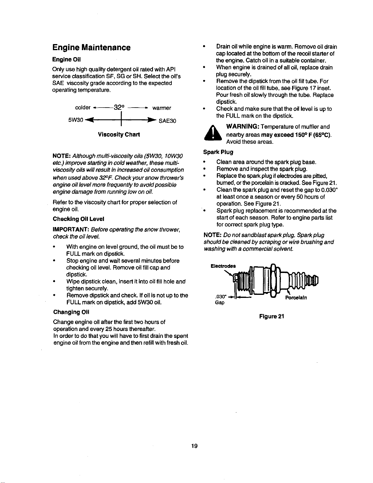
Spark Plug
• Clean area aroundthe sparkplug base.
• Remove and inspect the sparkplug.
• Replace the spark plug ifelectrodes are pitted,
burned, orthe porcelainiscracked. See Figure21.
• Clean the spark plug and reset the gap to 0.030"
at least once a season or every 50 hours of
operation. See Figure 21.
• Spark plug replacement is recommended at the
start of each season. Refer to engine parts list
for correct spark plug type.
NOTE: Do not sandblastspark plug. Spark plug
shouldbe cleaned by scrapingor wire brushing and
washing with a commercialsolvent.
Figure 21
19
A
WARNING: Always stop the engine,dis-
connectsparkplug wireand move itaway
fromthe spark plug beforeperformingany
adjustmentsor repairs,
Never attempt to clean thechute or make
any adjustmentswhilethe engine is running.
Adjustments
Traction Drive Control
Refer to the Final Adjustmentsectionofthe Set-Up
Instructionsto adjustthetraction drivecontrol.If you
are not sure ofproperadjustment,checkas follows.
• Drain thegasolineor place plasticfilm underthe
gascap ifthesnow throwerhasalready been
operated.
• Tipthe snowthrowerforward and remove the
four self-tappingscrewsthat holdtheframe
cover underneaththe snowthrower.
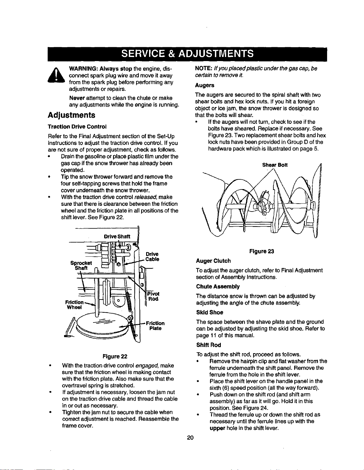
Withthe tractiondrivecontrolreleased, make
sure thatthere isclearance between thefriction
wheel and the friction plate in all positionsofthe
shiftlever. See Figure22.
"_l_ I I Drive
Sproc.e,
• IILIIIi._,i-II
,r,ct,on--...lli-tlLltL° Jill I
°,' Lon
Figure 22
With the tractiondrive controlengaged, make
surethat thefrictionwheel ismakingcontact
withthe friction plate,Alsomake sure that the
overtravelspringisstretched.
Ifadjustmentisnecessary,loosen thejam nut
on thetractiondrivecable and thread thecable
in or outas necessary.
Tightenthejam nutto securethe cable when
correctadjustmentisreached. Reassemble the
frame cover.
NOTE: ff you placed plasticunderthegas cap, be
certaintoremove it,
Augers
The augers are secured tothe spiral shaftwithtwo
shear boltsand hexlock nuts.Ifyou hit a foreign
objector ice jam, the snowthrower isdesigned so
that the boltswillshear.
• Iftheaugerswillnotturn, checktosee ifthe
boltshave sheared. Replace ifnecessary. See
Figure23. Two replacementshear boltsand hex
locknuts have been providedinGroup D ofthe
hardwarepackwhichisillustratedon page 5.
\
ShearBolt
20
Figure 23
Auger Clutch
To adjustthe augerclutch,refer toFinal Adjustment
sectionofAssemblyInstructions,
Chute Assembly
The distancesnow isthrowncan be adjusted by
adjustingthe angle of the chute assembly,
Skid Shoe
The space between the shave plate and the ground
can beadjusted byadjustingthe skid shoe. Refer to
page 11 of thismanual.
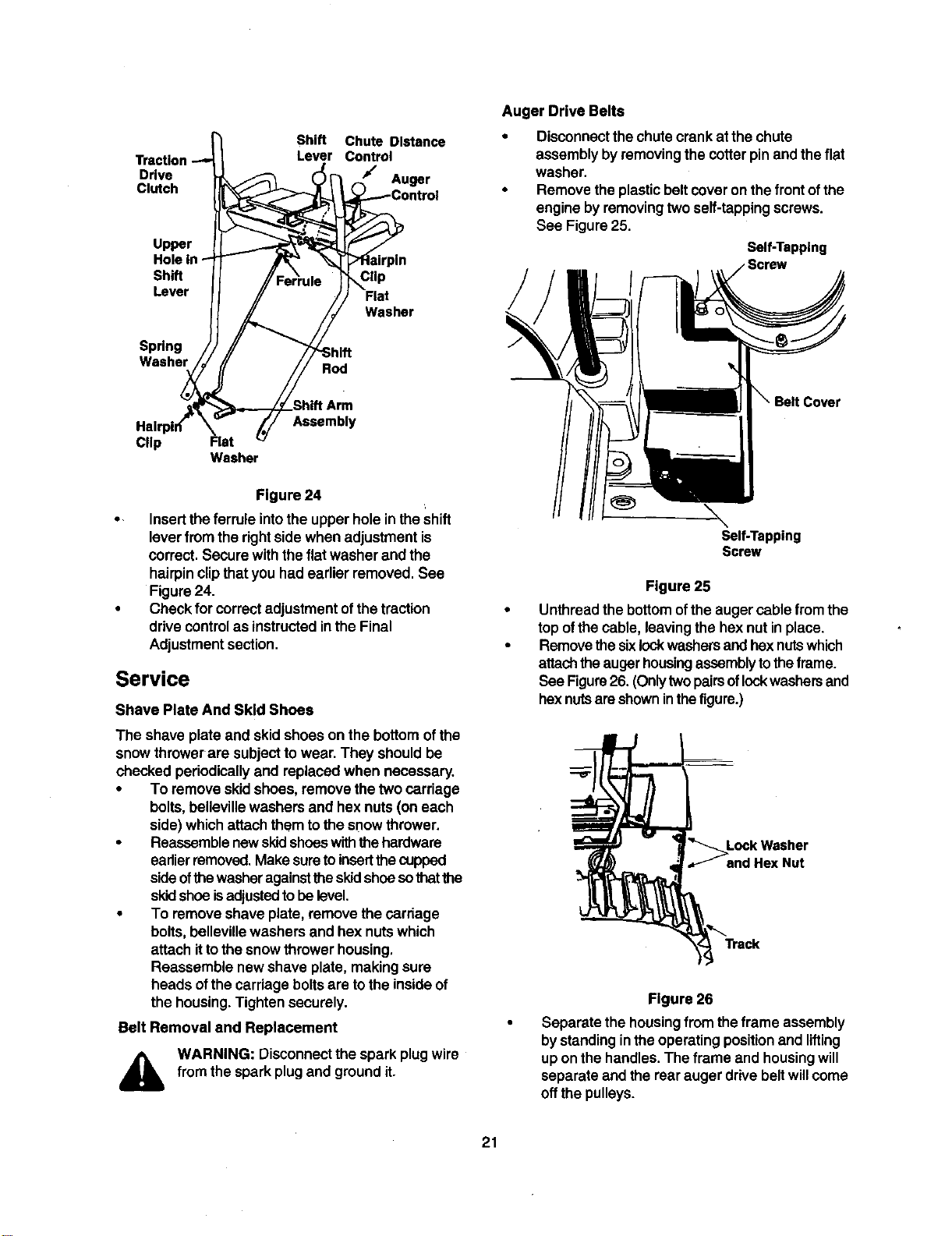
Shift Rod
Toadjust the shiftrod, proceed as follows.
• Remove thehairpin clipand flat washerfrom the
ferrule underneaththe shiftpanel. Remove the
ferrule from thehole inthe shiftlever.
• Place theshiftlever onthe handle panel inthe
sixth(6) speed position(all theway forward).
• Pushdown onthe shiftrod(and shift arm
assembly)as far as itwillgo. Holditin this
position.See Figure24.
• Thread the ferrule up or downthe shiftrodas
necessary untiltheferrule linesup withthe
upper holeinthe shiftlever.
Shift Chute Distance
Lever Control
Drive Auger
Clutch
Upper
Shift
Lever
Spring
Washer
Rod
Clip
Flat
Washer
Clip Flat
Washer
Assembly
Figure 24
• Inserttheferrule intothe upper holein theShift
lever fromthe rightsidewhen adjustmentis
correct.Secure with thefiatwasher and the
hairpinclipthatyou had earlier removed. See
Figure24.
• Check for correctadjustmentofthe traction
drivecontrolas instructedinthe Final
Adjustmentsection.
Service
Shave Plate And Skid Shoes
The shave plate and skidshoes on the bottomofthe
snow throwerare subjecttowear. They shouldbe
checked periodicallyand replaced when necessary.
• To remove skidshoes,remove the twocarriage
bolts,beUevillewashers and hex nuts(on each
side) whichattachthem tothe snowthrower.
• Reassemblenewskidshoeswiththe hardware
earlierremoved,Makesuretoinsertthecupped
sideofthewasheragainstthe skidshoesothatthe
skidshoe isadjusted tobelevel,
• To remove shave plate, removethe carriage
bolts, bellevillewashers and hex nutswhich
attach ittothesnow throwerhousing,
Reassemble newshave plate, makingsure
heads ofthe carriageboltsare tothe insideof
the housing.Tighten securely.
Belt Removal and Replacement
WARNING: Disconnect the spark plugwire
from thespark plugand groundit.
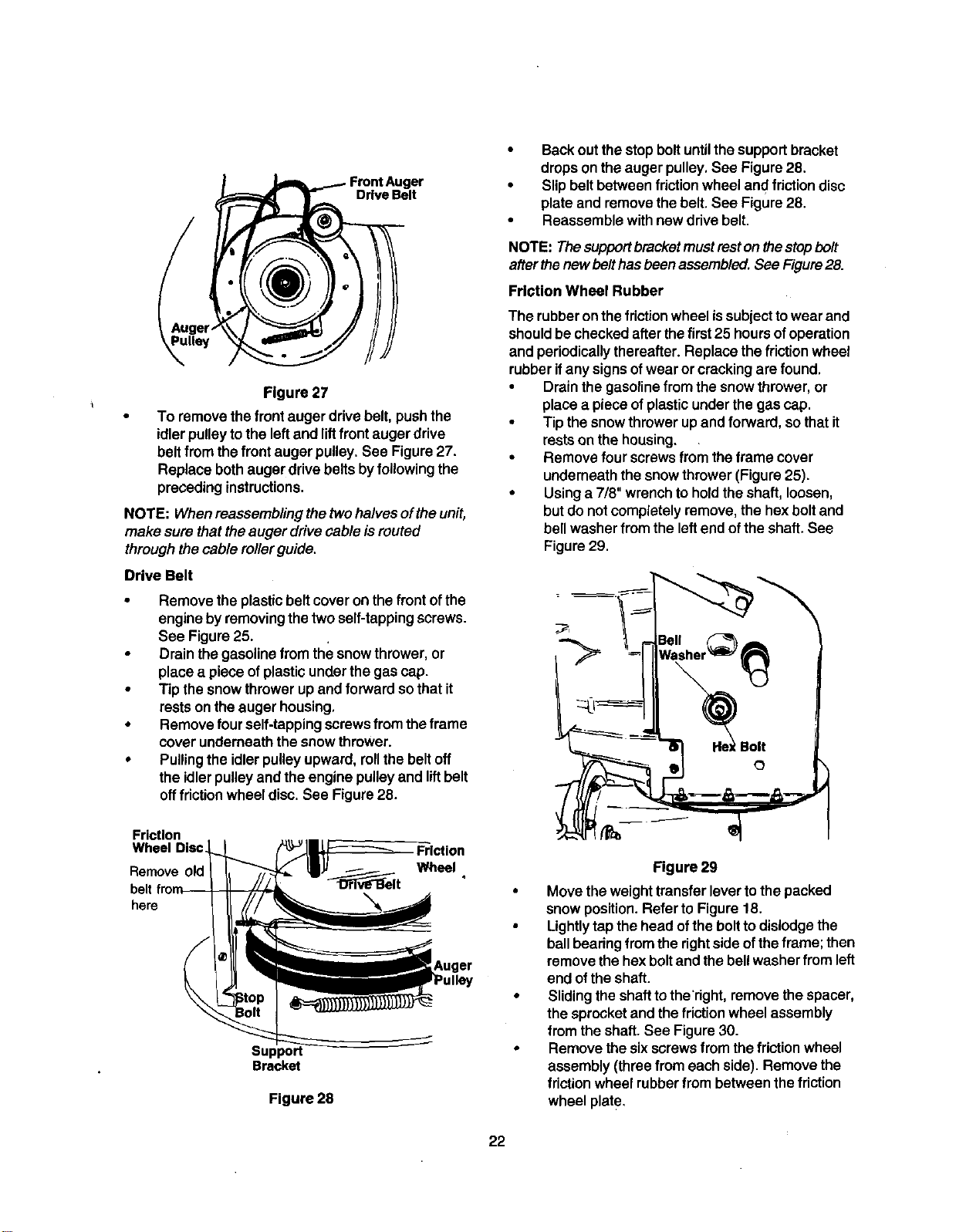
Auger Drive Belts
• Disconnectthechute crank at the chute
assembly byremoving the cotterpinandthe flat
washer.
• Remove the plasticbeltcover onthe frontofthe
engine byremovingtwoself-tappingscrews.
See Figure25,
Self-Tapping
Cover
\
Self-Tapping
Screw
Figure 25
Unthread the bottom ofthe augercable fromthe
top ofthe cable, leavingthe hex nut inplace.
Removethe sixlockwashersandhexnutswhich
attachtheaugerhousing assemblytotheframe.
See Figure26. (Onlytwopairsoflockwashersand
hexnutsareshowninthefigure.)
Lock Washer
and Hex Nut
Figure 26
Separate thehousingfrom theframe assembly
bystandinginthe operatingpositionand lifting
up onthe handles.The frame and housingwill
separate and the rearauger drivebeltwillcome
offthepulleys.
21
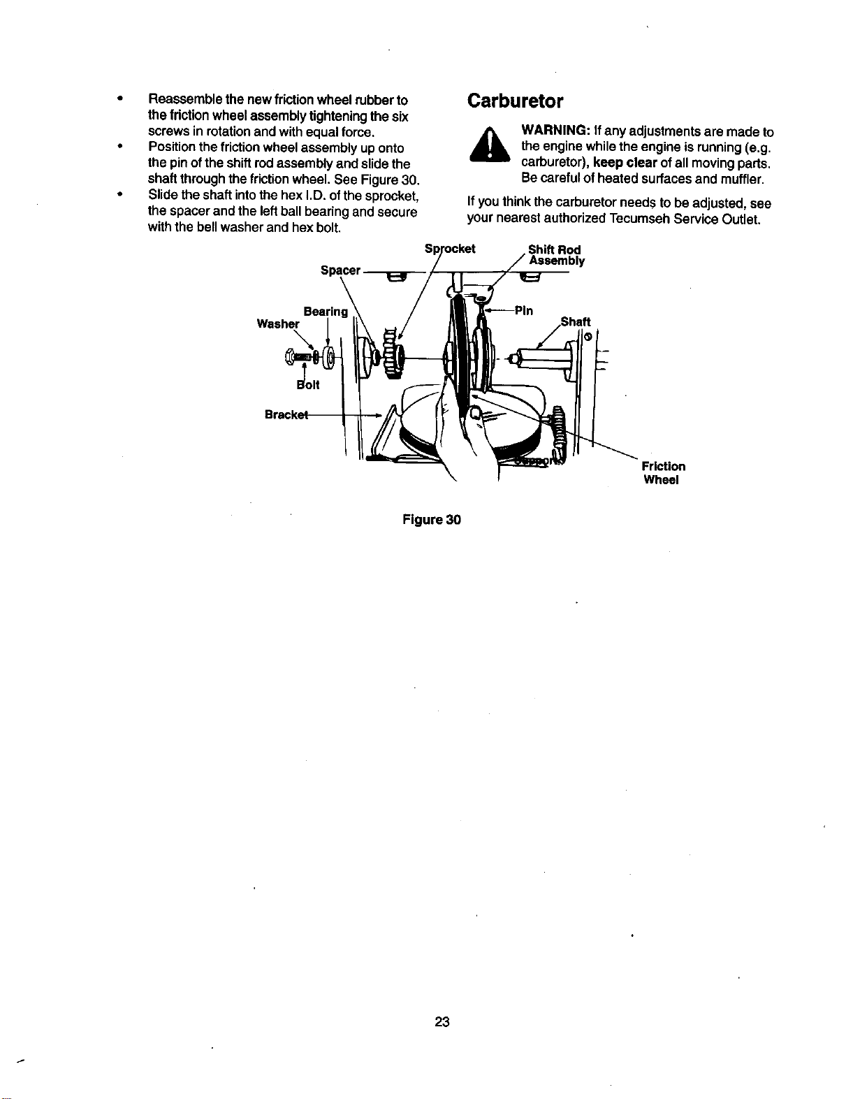
Drive Belt
Figure 27
To remove thefrontauger drivebelt,pushthe
idler pulleytothe leftand liftfront augerdrive
belt from the front auger pulley.See Figure27.
Replace bothaugerdrivebelts byfollowing the
precedinginstructions.
NOTE: When reassembling thetwohalvesoftheunit,
make sure thattheauger drivecable is routed
throughthe cable roller guide.
Drive Belt
• Remove the plasticbelt coveron the front ofthe
engine byremovingthetwo self-tappingscrews.
See Figure25.
• Drain thegasolinefrom the snowthrower,or
place a piece of plasticunderthe gascap.
• Tip the snowthrower upand forward sothat it
restsonthe auger housing,
• Remove four self-tappingscrewsfrom theframe
cover underneaththesnow thrower.
• Pullingthe idlerpulleyupward, rollthe beltoff
the idlerpulleyandthe engine pulleyand liftbelt
offfdction wheel disc. See Figure28.
Friction
Wheel Disc
Remove
belt
here
Friction
Wheel
Support
Bracket
Figure 28
• Backoutthe stopboltuntilthe supportbracket
dropson the augerpulley,See Figure28.
• Slipbelt betweenfriction wheel and friction disc
plate and removethe belt.See Figure28.
• Reassemble withnewdrive belt.
NOTE: Thesupportbracket must restonthestopbolt
afterthenew belthasbeen assembled. See Figure28.
Friction Wheel Rubber
The rubberonthe friction wheel issubjecttowear and
shouldbe checkedafterthefirst 25 hoursofoperation
and periodicallythereafter. Replace the friction wheel
rubberifany signsofwear or crackingare found.
• Drainthe gasolinefrom thesnow thrower,or
place a pieceof plasticunderthe gascap.
• Tip the snowthrowerupand forward, sothatit
restson the housing.
• Remove four screwsfrom the frame cover
underneaththesnow thrower(Figure25).
• Usinga 7/8" wrenchtoholdtheshaft, loosen,
butdo not completelyremove,the hexbolt and
bell washer from the leftend of theshaft. See
Figure29.
Figure 29
• Move the weighttransferlevertothe packed
snow position.Refer to Figure18.
• Lightlytapthe head ofthe boltto dislodgethe
ballbearingfrom the rightside oftheframe; then
remove thehexboltand the bellwasher from left
end ofthe shaft.
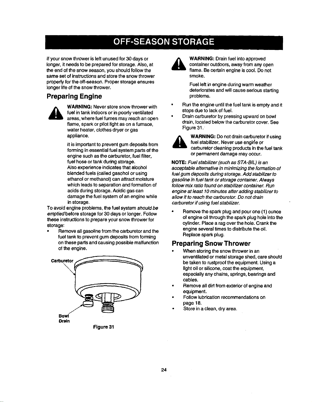
• Slidingthe shafttotheTight,remove thespacer,
the sprocketand the friction wheel assembly
from the shaft.See Figure30.
• Remove the sixscrewsfrom thefriction wheel
assembly (three from eachside). Remove the
friction wheel rubberfrom between thefriction
wheel plate.
22
• Reassemblethenewfrictionwheelrubberto
thefrictionwheelassemblytighteningthesix
screwsinrotationandwithequalforce.
• Positionthefrictionwheel assembly uponto
the pinofthe shiftrodassemblyand slidethe
shaftthroughthefriction wheel. See Figure30.
• Slidethe shaftintothe hexI.D. ofthe sprocket,
the spacer and the leftball bearingand secure
withthe bellwasher and hexbolt.
Carburetor
A
WARNING: Ifany adjustmentsare made to
the engine whilethe engine isrunning(e.g.
carburetor),keep clear ofall movingparts.
Becarefulofheated surfacesand muffler.
If youthinkthe carburetorneeds to be adjusted,see
yournearest authorizedTecumseh Service Outlet.
Shift Rod
ly
Washer
\
Friction
Wheel
Figure 30
23
If your snow thrower is leftunusedfor 30 days or
longer,it needsto be preparedfor storage. Also, at
the end of the snow season, you should follow the
same set of instructionsend store the snow thrower
properly for the off-season. Proper storageensures
longer life of the snow thrower.
Preparing Engine
A
WARNING: Never store snow thrower with
fuel intank indoors or in poorlyventilated
areas, where fuelfumes may reach an open
flame, spark or pilotlightas on a furnace,
water heater, clothesdryeror gas
appliance.
It isimportant to preventgum depositsfrom
forming inessential fuel systempartsofthe
engine suchas thecarburetor,fuel filter,
fuel hose ortank duringstorage.
Also experience indicatesthatalcohol
blendedfuels (called gasoholor using
ethanol or methanol)can attractmoisture
whichleads toseparationand formation of
acids duringstorage.Acidic gascan
damage the fuel system ofan engine while
instorage.
To avoidengine problems,the fuel system shouldbe
emptiedbefore storagefor 30 daysor longer.Follow
these instructionsto prepareyour snowthrowerfor
storage:
• Remove allgasolinefromthe carburetor and the
fueltank topreventgum depositsfrom forming
on thesepartsand causingpossiblemalfunction
of theengine.
Carburetor
\
Bowl
Drain
Figure 31
&
WARNING: Drain fuel intoapproved
containeroutdoors,away from any open
flame. Be certainengine iscool. Do not
smoke.
Fuel leftin engine duringwarm weather
deteriorates and willcauseseriousstarting
problems,
Run the engine untilthe fuel tankisempty and it
stopsdue to lack offuel.
Drain carburetor bypressingupwardon bowl
drain, located belowthecarburetorcover.See
Figure31.
&
WARNING: Do not drain carburetor ifusing
fuel stabilizer.Never use engirleor
carburetorcleaningproductsin thefuel tank
or permanent damage may occur.
NOTE: Fuel stabilizer(suchas STA-BIL) isan
acceptable alternativeinminimizing theformationof
fuelgum depositsduring storage.Add stabilizerto
gasoline in fuel tankor storage container.Always
followmix ratiofoundonstabilizer container.Run
engine at least 10minutesafter addingstabilizerto
allowittoreach thecarburetor.Do not drain
carburetorff usingfuelstabilizer.
Remove the spark plug and pour one (1) ounce
of engineoilthrough the spark plughole intothe
cylinder. Place a ragover the hole. Crank the
engine several times to distribute the oil.
Replace spark plug.
Preparing Snow Thrower
• When storingthe snowthrower inan
unventilatedor metalstorageshed,care should
betaken to rustprooftheequipment. Usinga
lightoilor silicone,coattheequipment,
especiallyanychains, springs,bearingsand
cables.
• Remove alldirtfrom exteriorofengine and
equipment.
Followlubricationrecommendationson
page 18.
Store ina clean,dry area.
24
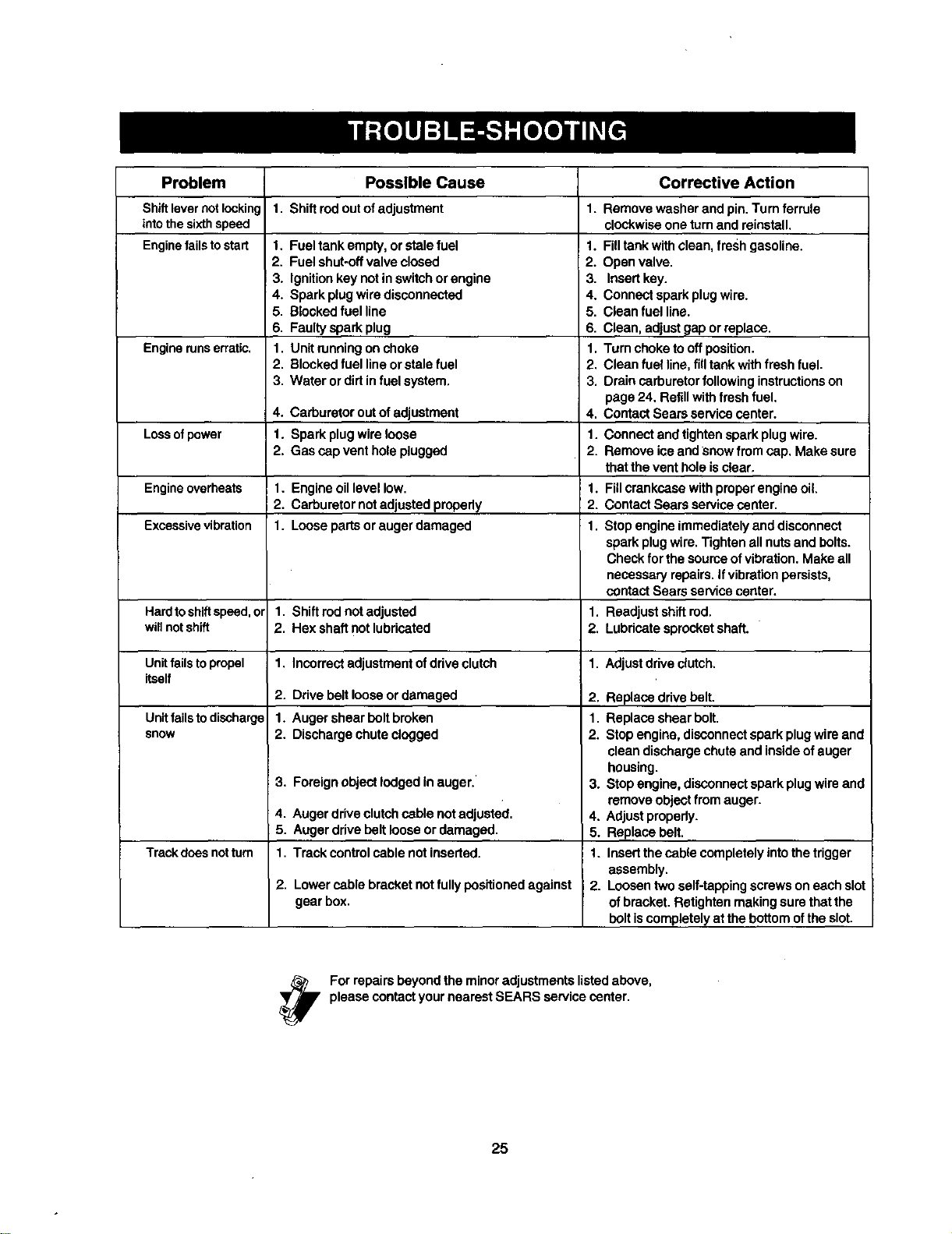
Problem
Shiftlevernotlocking
intothesixthspeed
Enginefailstostart
Engine runs erratic.
Lossofpower
Engineoverheats
Excessivevibration
Hardtoshiftspeed,or
willnotshift
Unitfails to propel 1.
itself
2.
Unitfails to discharge 1.
snow 2.
3,
4.
5.
Trackdoesnotturn 1.
2,
Possible Cause
1, Shiftrodoutofadjustment
1. Fueltank empty, or stale fuel
2. Fuelshut-oftvalve closed
3. Ignitionkey not inswitchor engine
4. Spark plugwire disconnected
5. Blockedfuel line
6. Faultyspark plug
1. Unitrunningonchoke
2. Blockedfuel lineorstale fuel
3. Water or dirtinfuel system.
4. Carburetor out of adjustment
1. Spark plugwireloose
2. Gas capvent hole plugged
1. Engineoil level low.
2. Carburetor notadjusted properly
1. Looseparts or augerdamaged
Corrective Action
1. Remove washer and pin. Turn ferrule
clockwiseone turnand reinstall,
1. Filltankwith clean, fresh gasoline.
2. Openvalve.
3. Insertkey.
4. Connect spark plugwire.
5. Clean fuel line.
6. Clean, adjustgap orreplace.
1. Turn choketo offposition.
2. Clean fuel line,fill tank withfresh fuel.
3. Drain carburetorfollowing instructionson
page 24, Refillwithfresh fuel.
4. Contact Sears servicecenter.
1. Connect and tightenspark plugwire.
2. Remove ice and snow fromcap, Make sure
thatthe vent hole isclear,
1. Fillcrankcase withproperengineoil
2. ContactSears service center.
1. Stopengine immediatelyand disconnect
spark plugwire. Tightenall nutsand bolts.
Check for the sourceofvibration. Make all
neceseePl repairs.If vibrationpersists,
contactSears servicecenter.
1. Shiftred notadjusted 1. Readjustshiftred.
2. Hex sha_lnot lubricated 2. Lubricatesprocket shaft.
Incorrectadjustmentof drive clutch 1. Adjustdriveclutch.
Ddve belt loose ordamaged 2. Replace drivebelt.
Auger shear boltbroken 1. Replace shear bolt.
Discharge chute clogged 2. Stopengine, disconnectspark plugwire and
Foreignobject lodgedin auger.'
Auger drive clutchcable not adjusted.
Auger drive beltloose ordamaged.
Track controlcable not inserted.
Lowercable bracket not fullypositionedagainst
gear box.
cleandischargechute and insideofauger
housing.
3. Stopengine, disconnectspark plugwire and
removeobjectfrom auger.
4. Adjustpropady.
5. Replace belt.
1. Insertthe cable completelyintothe trigger
assembly.
2. Loosentwo self-tappingscrews oneach slot
ofbracket. Retighten makingsure thatthe
bolt iscompletelyat the bottom ofthe slot.
Forrepairsbey°nd the min°r adjustmentslistedabove'
please contactyour nearestSEARS service center.
25
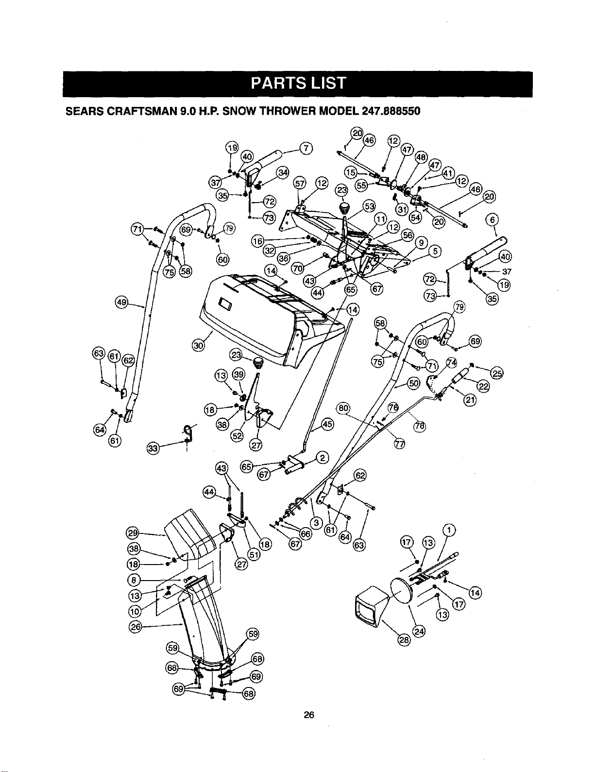
SEARS CRAFTSMAN 9.0 H.P. SNOW THROWER MODEL 247.888550
26
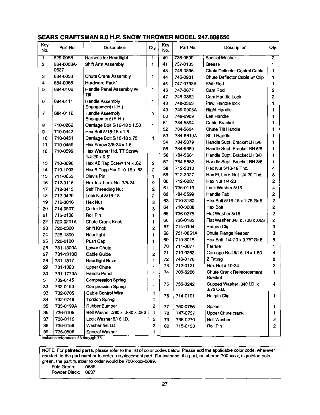
SEARS CRAFTSMAN 9.0 H.P. SNOW THROWER MODEL 247.888550
Key
No.
1
2
3
4
6
8
9
10
11
12
13
14
15
16
17
18
19
20
21
22
23
24
25
26
27
28
29
30
31
32
33
34
35
36
37
38
39
Part No.
629-0058
684-0008A-
0637
684-0053
684-0066
684-0102
684-0111
684-0112
710-0262
710-0442
710-0451
710-0459
710-0599
710-0896
710-1003
711-0653
712-0116
712-0415
712-0429
712-3010
714-0507
715-0138
720-0201A
Description
Harnessfor Headlight
ShiftArm Assembly
Chute Crank Assembly
Hardware Pack*
Handle Panel Assembly w/
Tilt
HandleAssembly
Engagement (L.H.)
Handle Assembly
Engagement (R.H.)
Carriage Bolt5/16-18 x 1.50
Hex Bolt5/16-18 x 1.5
Carriage Bolt5/16-18 x.75
Hex Screw 3/8-24 x 1.5
Hex Washer Hd. 3-1"Screw
1/4-20 x 0.5"
Hex AB Tap Screw 1/4 x .62
Hex B-TappScr # 10-16 x .62
Clevis Pin
Hex Ins.Look Nut3/8-24
Self Threading Nut
Lack Nut 5/16-18
Hex Nut
Cotter Pin
Roll Pin
Chute Crank Knob
Qty,
1
1
1
1
1
1
1
1
2
2
1
9
2
2
3
3
1
1
KeY Part No.
No,
40 736-0509
41 737-0133
43 746-0896
44 746-0901
45 747-0798A
46 747-0877
47 748-0362
48 748-0363
49 749-0908A
50 749-0909
51 784-5594
52 784-5604
53 784-5619A
54 784-5679
55 784-5680
56 784-5681
57 784-5682
58 712-3010
59 '12-3027
60 _12-0287
61 736-0119
62 784-5599
63 710-3180
64 710-3008
65 736-0275
66 736-0185
720-0300 ShiftKnob
725-1300 Headlight
726-0100 Push Cap
731-1300A Lower Chute
731-1313C Cable Guide
731-1317 HeadlightBezel
731-1320 Upper Chute
731-1773A Handle Panel
2 67 714-0104
1 68 731-0851A
1 69 710-3015
1 70 711-0677
2 71 710-0262
1 72 746-0778
1 73 712-0121
1 74 705-5266
732-0145
732-0193
732-0705
732-0746
735-0199A
736-0105
736-0119
736-0159
736-0506
CompressionSpring
CompressionSpring
Cable Control Wire
TorsionSpring
RubberBumper
BellWasher .380 x .880 x .062
LockWasher 5/16 I.D.
Washer 5/6 I.D.
SpecialWasher
1
75
1
1
76
1
2 77
t 78
2 79
2 80
736-0242
714-0101
750-0785
747-0737
736-0270
7t5-0138
Description
SpecialWasher
Grease
Chute DeflectorControlCable
Chute DeflectorCable w/Clip
Shift Rod
Cam Rod
Cam Handle Lock
Pawl Handle lock
RightHandle
LeftHandle
Cable Bracket
ChuteTilt Handle
ShiftHandle
Handle Supt. Bracket LH 5/8
Handle Supt. B_'acketRH5/8
Handle Supt. Bracket LH 3/8
Handle Supt. Bracket RH 3/8
Hex Nut 5/16-18 Thd.
Hex FI. LockNut 1/4-20 Thd.
Hex Nut 1/4-20
LockWasher 5/16
HandleTab
Hex Bolt5/16-18 x 1.75 Gr.5
Hex Bolt
Flat Washer 5/16
Flat Washer 3/6 x ,738 x .063
HairpinClip
Chute Flange Keeper
Hex Bolt 1/4-20 x 0.75" Gr.5
Ferrule
Cardage Bolt5/16-18 x 1.50
Z Fitting
Hex Nut # 10-24
Chute Crank Reinforcement
Bracket
CuppedWasher .340 I.D.x
.872O.D.
HairpinClip
Spacer
Upper Chutecrank
BellWasher
;Roll Pin
• Includes references 58 through 75
Qty.
2
1
1
1
1
2
2
1
1
1
1
1
1
1
1
1
1
4
8
2
4
2
2
2
2
2
3
3
8
1
4
2
2
1
4
1
1
2
2
NOTE: Forpainted parts, please referto the listofcolorcodes below. Please add the applicable colorcode, wherever
needed, to the part number to ordera replacement part. For instance, ifa part, numbered 700-xxxx, is paintedpolo
green, the part number to orderwould be 700-xxxx-0689.
PoloGreen: 0689
PowderBlack: 0637
27
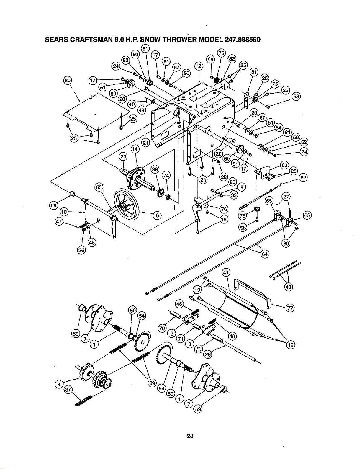
SEARS CRAFTSMAN 9.0 H.P. SNOW THROWER MODEL 247.888550
28
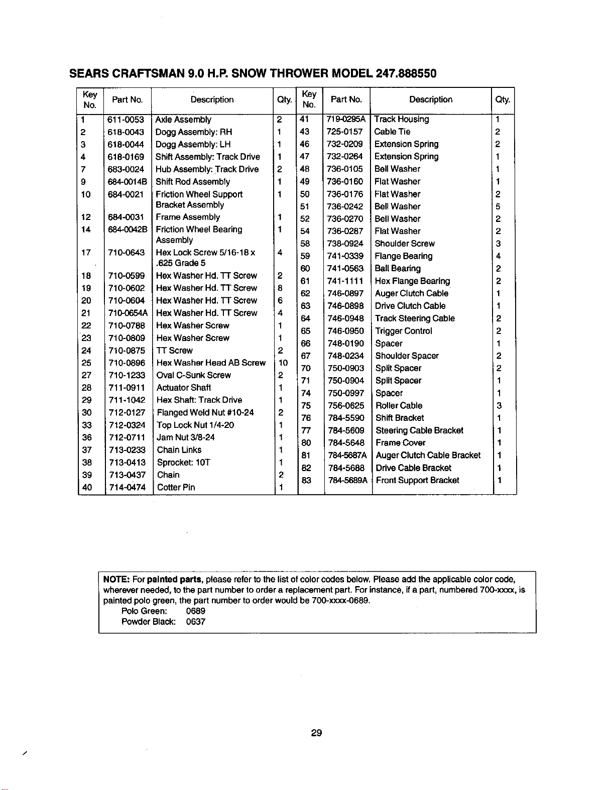
SEARS CRAFTSMAN 9.0 H.P. SNOW THROWER MODEL 247.888550
Key Part No.
No.
611-0053
2 618-0043
3 618-0044
4 618-0169
7 683-0024
9 684-0014B
10 684-0021
12
14
17
18
19
20
21
22
23
24
25
27
28
29
i 30
33
36
37
38
39
40
684-0031
r_4-0042B
710-0643
710-0599
710-0602
710-0604
710-0654A
710-0788
710-0809
710-0875
710-0898
710-1233
711-0911
711-1042
712-0127
712-0324
7!2-0711
713-0233
713-0413
713-0437
714-0474
Description
Key Part No.
No.
41 719-0295A
43 725-0157
46 732-0209
47 732-0264
48 736-0105
49 736-0160
50 738-0176
51 736-0242
52 736-0270
54 736-0287
58 738-0924
59 741-0339
60 741-0563
61 741-1111
62 746-0897
63 746-0898
64 746-0948
65 746-0950
66 748-0190
67 748-0234
70 750-0903
71 750-0904
74 750-0997
75 756-0625
76 784-5590
77 784-5609
80 784-5648
81 784-5687A
82 784-5688
83 784-5689A
Axle Assembly
Dogg Assembly:RH
DoggAssembly:LH
Qty.
2
ShiftAssembly:Track Dnve
HubAssembly: Track Drive 2
ShiftRodAssembly
FrictionWheel Support
Bracket Assembly
Frame Assembly
FrictionWheel Bearing
Assembly
Hex LockScrew 5/16-18 x 4
.625 Grade 5
Hax Washer Hd. "17"Screw 2
Hex Washer Hd. TT Screw 8
Hex Washer Hd, TT Screw 6
Hex Washer Hd. TT Screw 4
Hex Washer Screw 1
Hex Washer Screw 1
TT Screw 2
HexWasher Head AB Screw 10
Oval C-Sunk Screw 2
Actuator Shaft 1
Hex Shaft:Track Ddve 1
Flanged Weld Nut #10-24 2
Top LockNut 1/4-20 i 1
Jam Nut 3/8-24 1
Chain Links 1
Sprocket: 10T 1
Chain 2
Cotter Pin 1
Description
Qty.
Track Housing 1
Cable Tie 2
Extension Spring 2
Extension Spring 1
BellWasher t
Flat Washer I 1
Flat Washer 2
BellWasher 5
BellWasher 2
Flat Washer 2
ShoulderScrew 3
Flange Bearing 4
BallBeadng 2
Hex Flange Bearing 2
Auger ClutchCable 1
Drive ClutchCable 1
Track Steering Cable 2
TriggerControl 2
Spacer 1
ShoulderSpacer 2
Split Spacer 2
SplitSpacer 1
Spacer 1
RollerCable 3
ShiftBracket 1
SteeringCable Bracket 1
Frame Cover 1
AugerClutch Cable Bracket 1
Drive Cable Bracket 1
FrontSupportBracket 1
NOTE: Forpainted parts, please refer to the listofcolorcodes below.Please add the applicable colorcode,
wherever needed, to the part number to ordera replacement part. Forinstance, ifa part, numbered700-xxxx, is
painted polo green, the part number to orderwould be 700-xxxx-0689.
Polo Green: 0689
Powder Black: 0637
f
29
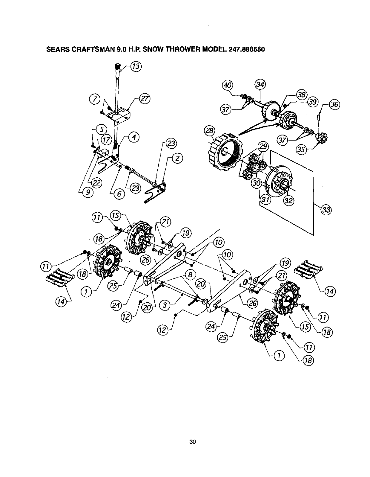
SEARS CRAFTSMAN 9.0 H.P. SNOW THROWER MODEL 247.888550
®
®
30
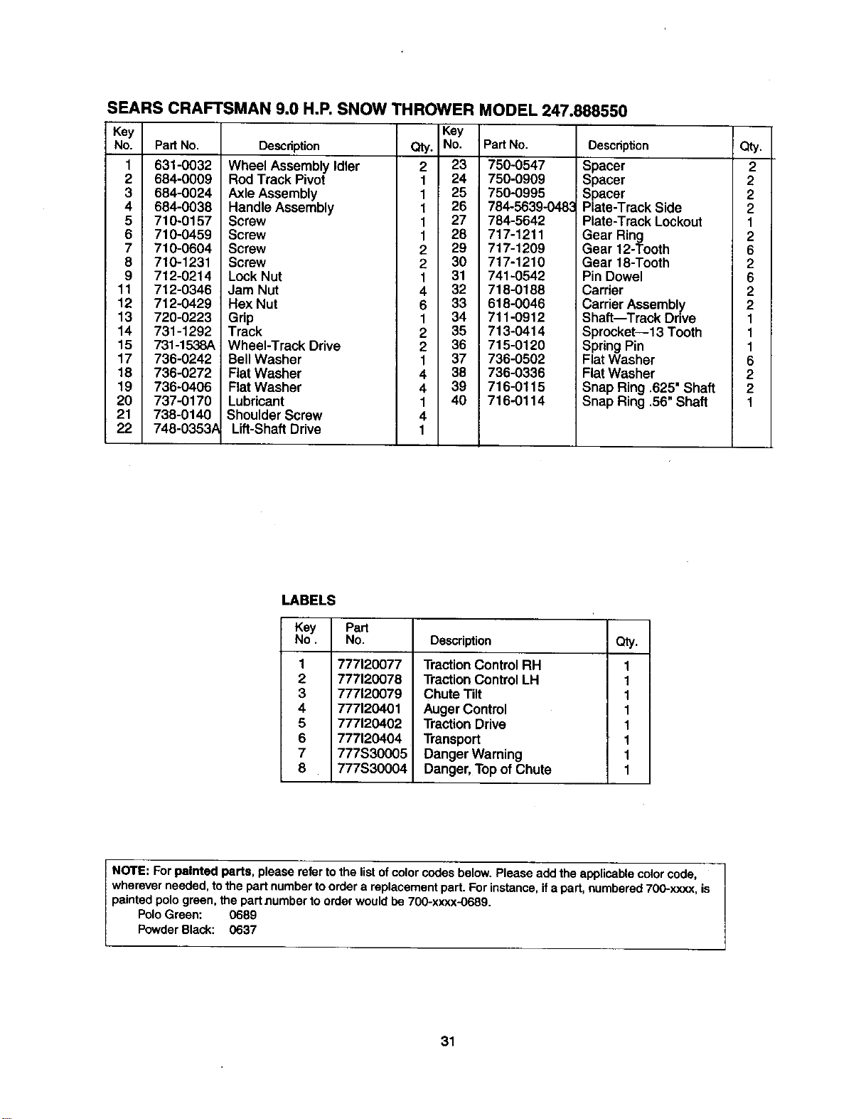
SEARS CRAFTSMAN 9.0 H.P. SNOW THROWER MODEL 247.888550
Key
No. PartNo.
1 631-0032
2 684-0009
3 684-0024
4 684-0038
5 710-0157
6 710-0459
7 710-0604
8 710-1231
9 712-0214
11 712-0346
12 712-0429
13 720-0223
14 731-1292
15 731-1538A
17 736-0242
18 736-0272
19 736-0406
20 737-0170
21 738-0140
22 748-0353,_
Key
Description Qty. No.
Wheel AssemblyIdler 2 23
Rod Track Pivot 1 24
Axle Assembly 1 25
Handle Assembly 1 26
Screw 1 27
Screw 1 28
Screw 2 29
Screw 2 30
Lock Nut 1 31
Jam Nut 4 32
Hex Nut 6 33
Grip 1 34
Track 2 35
Wheel-Track Drive 2 36
BellWasher 1 37
Flat Washer 4 38
Flat Washer 4 39
Lubricant 1 40
Shoulder Screw 4
Lift-ShaftDrive 1
PadNo.
750-0547
750-0909
750-0995
784-5639-048_
784-5642
717-1211
717-1209
717-1210
741-0542
718-0188
618-0046
711-0912
713-0414
715-0120
738-0502
736-0336
716-0115
716-0114
Description Qty.
Spacer 2
Spacer 2
Spacer 2
Plate-Track Side 2
Plate-Track Lockout 1
Gear Ring 2
Gear 12-Tooth 6
Gear 18-Tooth 2
Pin Dowel 6
Carrier 2
CarrierAssembly 2
Shaft--Track Drive 1
Sprocket--13 Tooth 1
SpringPin 1
Flat Washer 6
Flat Washer 2
Snap Ring .625' Shaft 2
Snap Ring .56" Shaft 1
LABELS
Key Part
No. No. Description Qty.
1
2
3
4
5
6
7
8
777120077
777120078
777120079
777120401
777120402
777120404
777S30005
777S30004
TractionControl RH
TractionControl LH
Chute Tilt
Auger Control
TractionDrive
Transport
Danger Warning
Danger,Topof Chute
1
1
1
1
1
1
1
1
NOTE: Forpainted parts, please referto the listof color codes below. Please add the applicable color code,
wherever needed, tothe part numbertoorder a replacement part. For instance,if apart, numbered700-x.xxx,is
painted polo green, the partnumber to order would be 700-xxxx-0689.
PoloGreen: 0689
PowderBlack: 0637
31
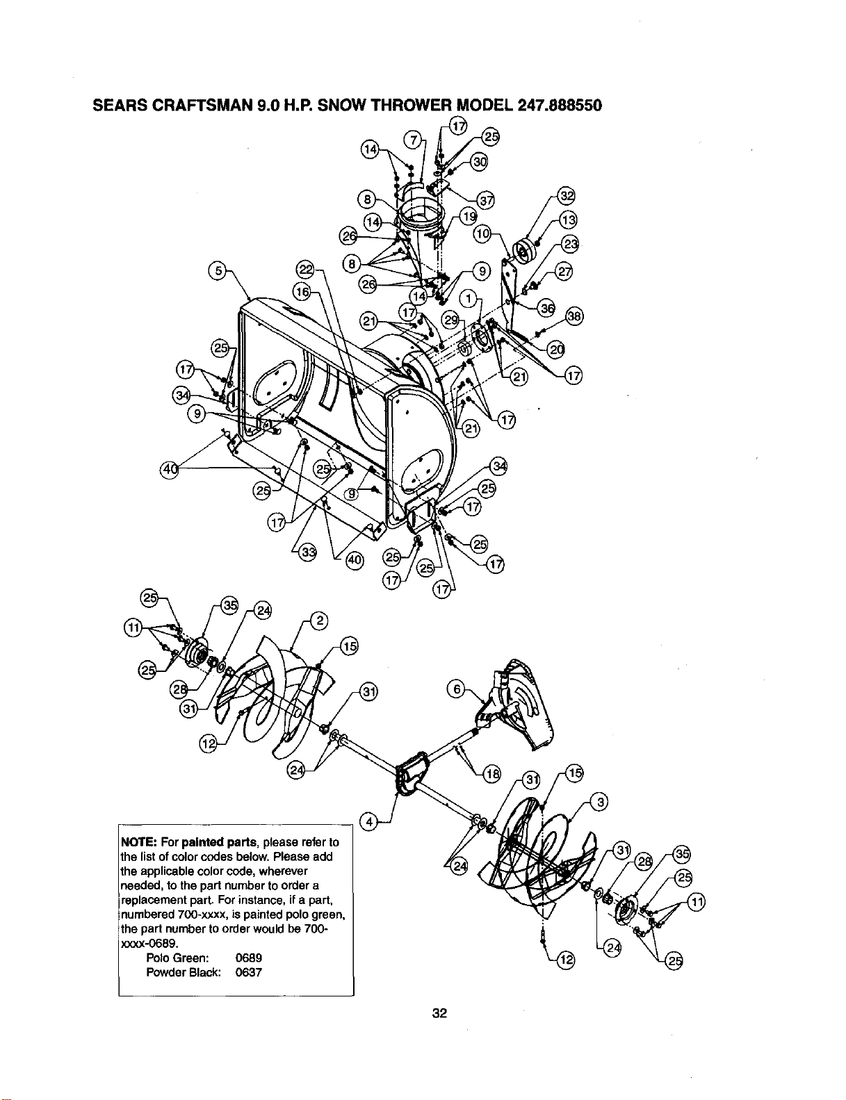
SEARS CRAFTSMAN 9.0 H.P. SNOW THROWER MODEL 247.888550
NOTE: For painted parts, please referto
the listof color codes below. Please add
the applicablecolorcode, wherever
needed, to the part numberto order a
replacement part. For instance, ifa part,
numbered700-xxxx, is painted pologreen,
the part number toorder would be 700-
xxxx-068g.
Polo Green: 0689
Powder Black: 0637
32
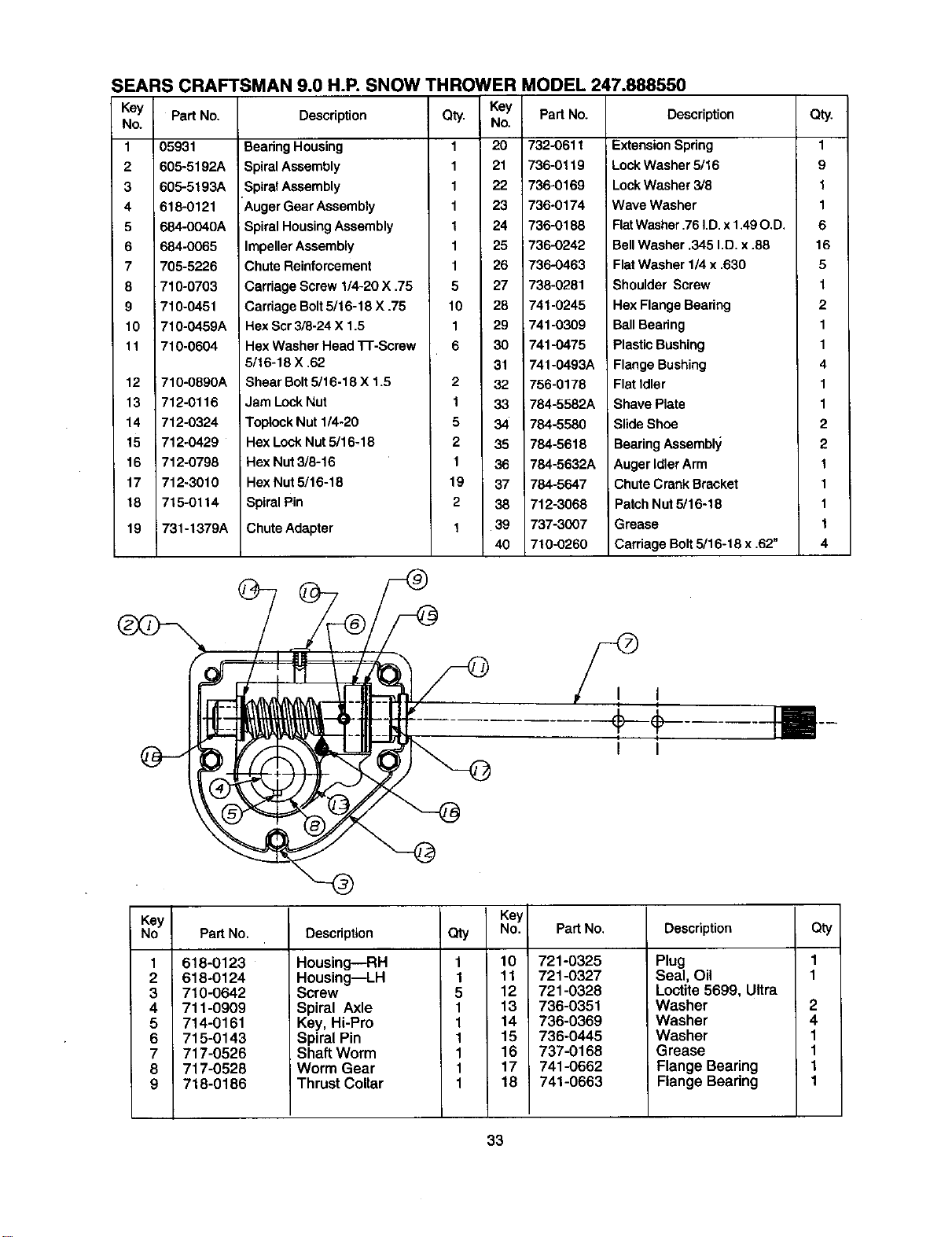
SEARS CRAFTSMAN 9.0 H.R SNOW THROWER MODEL 247.888550
Key Pad No.
No.
1 05931
2 605-5192A
3 605-5193A
4 618-0121
5 684-0040A
6 684-0065
7 705-5226
8 710-0703
9 710-0451
10 710-0459A
It 710-0604
12
13
14
15
16
17
18
19
710-0890A
712-0116
712-0324
712-0429
712-0798
712-3010
715-0114
731-1379A
Key Part No.
Description Qty. No.
Bearing Housing 1 20 732-0611
SpiralAssembly 1 21 736-0119
SpiralAssembly 1 22 736-0169
Auger Gear Assembly 1 23 736-0174
Spiral HousingAssembly t 24 736-0188
ImpellerAssembly 1 25 736-0242
Chute Reinforcement 1 26 736-0463
Carriage Screw I/4-20 X ,75 5 27 738-0281
Carriage Bolt5/16-18 X .75 10 28 741-0245
HexScr 3/8-24 X 1,5 1 29 741-0309
Hex Washer Head 1-r-Screw 6 30 741-0475
5/16-18 X .62 31 741-0493A
Shear Bolt5/16-18 X 1.5 2 32 756-0178
Jam LockNut 1 33 784-5582A
Toptock Nut 1/4-20 5 34 784-5580
Hex Lock Nut 5116-18 2 35 784-5618
Hex Nut 3/8-16 1 36 784-5632A
Hex Nut 5/16-18 19 37 784-5647
Spiral Pin 2 38 712-3068
Chute Adapter 1 39 737-3007
40 710-0260
Description Qty.
ExtensionSpdng 1
LockWasher 5/16 9
LookWasher 3/8 1
Wave Washer 1
FlatWasher.76 I.D.x 1,49O.D. 6
BellWasher .345 I.D. x .88 16
Flat Washer 1/4 x .630 5
Shoulder Screw f
Hex Flange Beadeg 2
Ball Bearing 1
:Plastic Bushing 1
Flange Bushing 4
Flat Idler 1
Shave Plate 1
Slide Shoe 2
BearingAssembl,/ 2
Auger IdlerArm 1
Chute Crank Bracket 1
Patch Nut 5/16-18 1
Grease 1
Carriage Bolt5/16-18 x .62" 4
I i
I I
Key
NO
1
2
3
4
5
6
7
8
9
Part No.
618-0123
618-0124
710-0642
711-0909
714-0161
715-0143
717-0526
717-0528
718-0186
Descdpfion
Housing---RH
Housing--LH
Screw
Spiral Axle
Key, Hi-Pro
Spiral Pin
ShaftWorm
IWorm Gear
Thrust Collar
aty
1
1
5
1
1
1
1
1
1
Key
No.
10
11
12
13
14
15
16
17
18
Part No,
721-0325
721-0327
721-0328
736-0351
736-0369
736-0445
737-0168
741-0662
741-0663
Descdption
Plug
Seal, Oil
Lo_ite 5699, Ultra
Washer
Washer
Washer
Grease
Flange Bearing
Flange Beadng
c_y
2
4
1
1
1
1
33
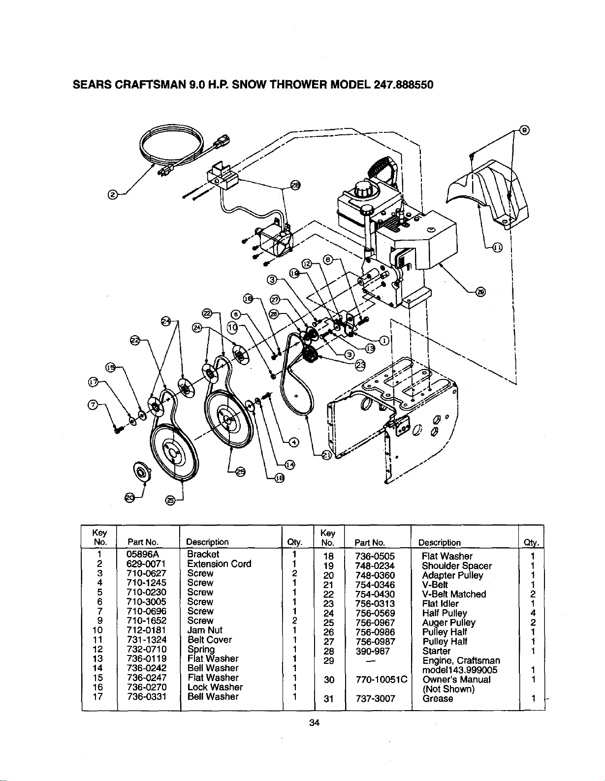
SEARS CRAFTSMAN 9.0 H.P. SNOW THROWER MODEL 247.888550
Key
No.
1
2
3
4
5
6
7
9
10
11
12
13
14
15
16
17
Pad No.
05896A
629-0071
710-0627
710-1245
710-0230
710-3005
710-0696
710-1652
712-0181
731-1324
732-0710
736-0119
736-0242
736-0247
736-0270
736-0331
Description
Bracket
ExtensionCord
Screw
Screw
Screw
Screw
Screw
Screw
Jam Nut
Belt Cover
Spring
Flat Washer
BellWasher
Flat Washer
Lock Washer
Bell Washer
Key
Qty. No.
1 18
1 19
2 20
1 21
1 22
1 23
1 24
2 25
1 26
1 27
1 28
1 29
1
1 30
1
1 31
PadNo.
736-0505
748-0234
748-0360
754-0346
754-0430
756-0313
756-0569
756-0967
756-0986
756-0987
390-987
770-10051C
737-3007
Description
Flat Washer
Shoulder Spacer
Adapter Pulley
V-Belt
V-Belt Matched
Flat Idler
Half Pulley
Auger Pulley
PulleyHalf
PulleyHalf
Starter
Engine, Craftsman
model143,999005
Owner's Manual
(Not Shown)
Grease
Qt_,
1
1
1
1
2
1
4
2
1
1
1
34
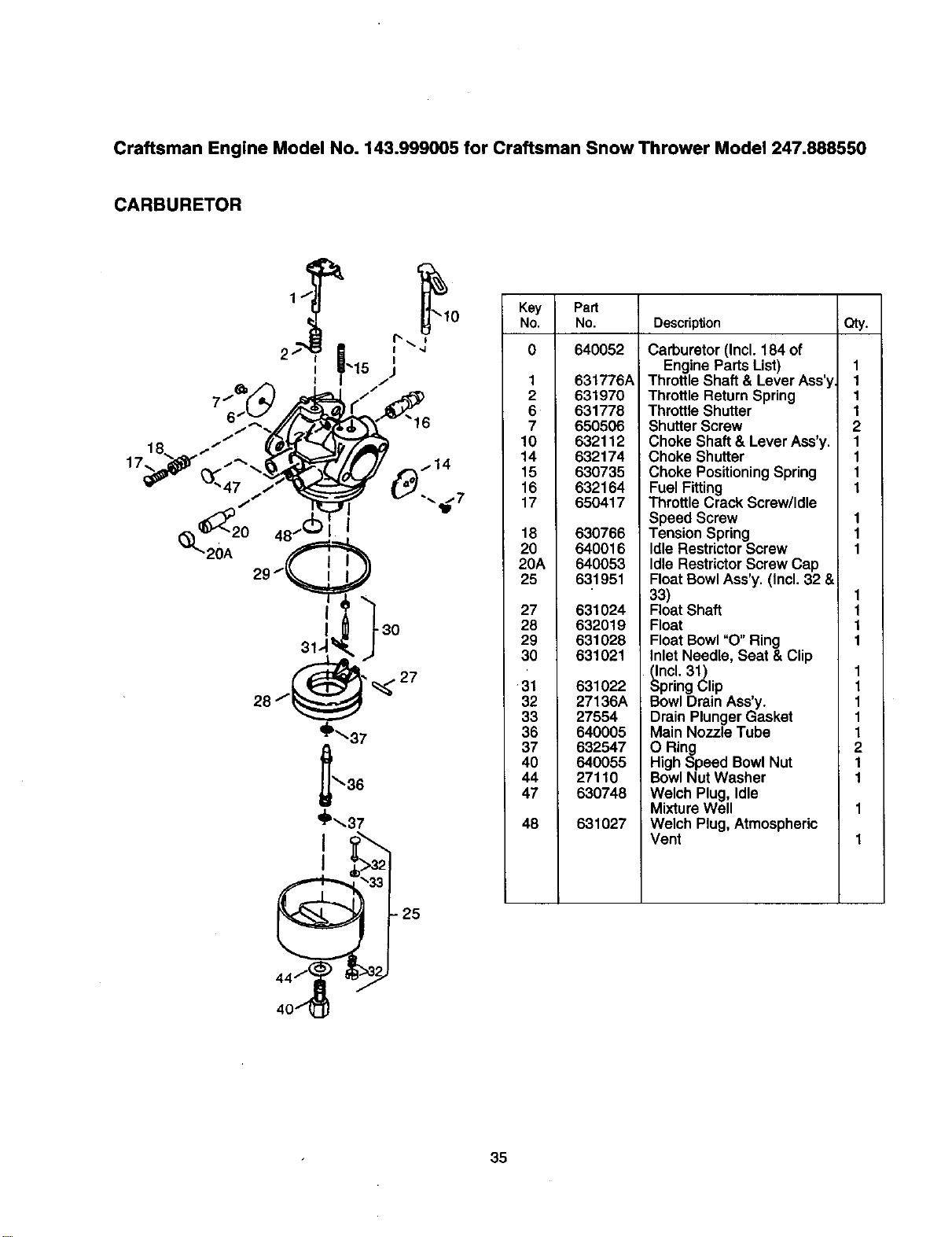
Craftsman Engine Model No. 143.999005 for Craftsman Snow Thrower Model 247.888550
CARBURETOR
20A
I
_P_37
"25
Key Part
No. No. Description Qty.
0 640052
1 631776A
2 631970
6 631778
7 650506
10 632112
14 632174
15 630735
16 632164
17 650417
18 630766
20 640016
20A 640053
25 631951
27 631024
28 632019
29 631028
30 631021
31
32
33
36
37
40
44
47
48
631022
27136A
27554
640005
632547
640055
27110
630748
631027
Carburetor (Incl. 184 of
Engine Parts List)
Throttle Shaft & Lever Ass'y
Throttle Return Spring
Throttle Shutter
Shutter Screw
Choke Shaft & Lever Ass'y.
Choke Shutter
Choke Positioning Spring
Fuel Fitting
ThrottleCrack Screw/Idle
Speed Screw
TensionSpring
IdleRestrictorScrew
Idle RestrictorScrew Cap
FloatBowlAss'y. (Incl. 32 &
33)
FloatShaft
Float
Float Bowl"O" Ring
InletNeedle, Seat & Clip
(Incl. 31)
SpringClip
BowlDrain Ass'y.
Drain Plunger Gasket
Main Nozzle Tube
O Ring
High Speed Bowl Nut
BowlNut Washer
Welch Plug, Idle
Mixture Well
Welch Plug, Atmospheric
Vent
1
1
1
1
2
1
1
1
1
I
I
I
1
1
1
1
1
1
1
1
1
2
1
1
35
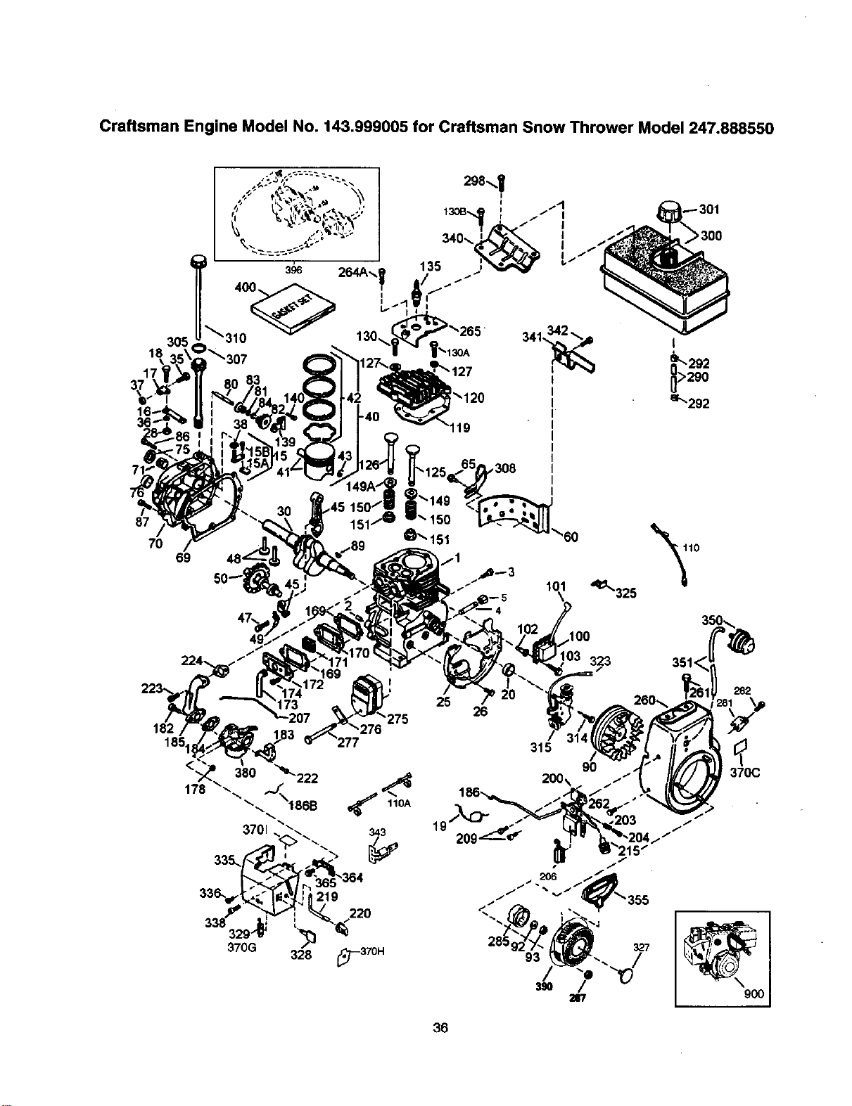
Craftsman Engine Model No. 143.999005 for Craftsman Snow Thrower Model 247.888550
305
18
87
70
69
224.
182
185.
!_120
,308
101
173 25
26
"275
315
200x
36
'q_325
323
9O
f
f
327
>300
282
370C
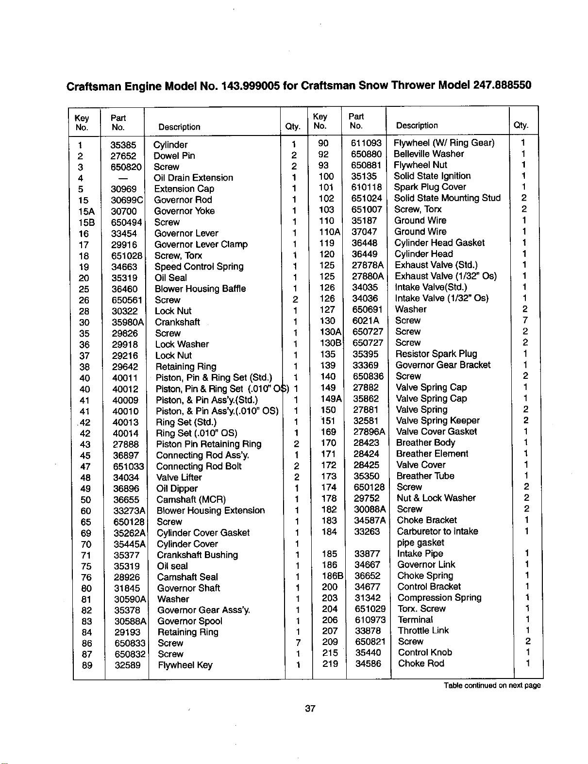
Craftsman Engine Model No. 143.999005 for Craftsman Snow Thrower Model 247.888550
Key
No.
1
2
3
4
5
15
15A
15B
16
17
18
19
20
25
26
28
30
35
36
37
38
40
40
41
41
42
42
43
45
47
48
49
50
60
65
69
70
71
75
76
80
81
82
83
84
86
87
89
Part
No.
35385
27652
650820
30969
30699C
30700
650494
33454
29916
651028
34663
35319
36460
650561
30322
35980A
29826
29918
29216
29642
40011
40012
40009
40010
40013
40014
27888
36897
651033
34034
36896
36655
33273A
650128
35262A
35445A
35377
35319
28926
31845
30590A
35378
30588A
29193
650833
650832_
32589
Description Qty.
Cylinder 1
Dowel Pin 2
Screw 2
Oil Drain Extension 1
Extension Cap 1
Governor Rod 1
GovernorYoke 1
Screw 1
Governor Lever 1
Governor Lever Clamp 1
Screw,Torx 1
Speed Control Spring 1
Oil Seal 1
Blower HousingBaffle 1
Screw 2
Lock Nut 1
Crankshaft 1
Screw 1
Lock Washer 1
Lock Nut 1
Retaining Ring 1
Piston, Pin & Ring Set (Std.) 1
Piston, Pin & RingSet (.010" O ;) 1
Piston, & Pin Ass'y.(Std.) 1
Piston, & Pin Ass'y.(.010" OS) 1
Ring Set (Std.) 1
Ring Set (.010" OS) 1
PistonPin Retaining Ring 2
Connecting RodAss'y. 1
Connecting Rod Bolt 2
Valve Lifter 2
Oil Dipper 1
Camshaft (MCR) 1
BlowerHousing Extension 1
Screw 1
Cylinder CoverGasket 1
Cylinder Cover 1
Crankshaft Bushing 1
Oil seal 1
Camshaft Seal 1
GovernorShaft 1
Washer 1
GovernorGear Asss'y. 1
GovernorSpool 1
Retaining Ring 1
Screw 7
Screw 1
Flywheel Key 1
Key Part
No. No.
90 611093
92 650880
93 650881
100 35135
101 610118
102 651024
103 651007
110 35187
110A 37047
119 36448
120 36449
125 27878A
125 27880A
126 34035
126 34036
127 650691
130 6021A
130A 650727
130B 650727
135 35395
139 33369
140 650836
149 27882
149A 35862
150 27881
151 32581
169 27896A
170 28423
171 28424
172 28425
173 35350
174 6501281
178 29752
182 30088A
183 34587A
184 33263
185 33877
186 34667
186B 36652
200 34677
203 31342
204 651029
206 610973
207 33878
209 650821
215 35440
219 34586
Description Qty.
Flywheel (W/Ring Gear) 1
BellevilleWasher 1
Flywheel Nut 1
Solid State Ignition 1
Spark PlugCover 1
Solid State MountingStud 2
Screw,Torx 2
Ground Wire 1
Ground Wire 1
Cylinder Head Gasket 1
Cylinder Head 1
Exhaust Valve (Std.) 1
Exhaust Valve (1/32" Os) 1
Intake Valve(Std.) 1
Intake Valve (1/32" Os) 1
Washer 2
Screw 7
Screw 2
Screw 2
Resistor Spark Plug 1
Governor Gear Bracket 1
Screw 2
Valve Spring Cap 1
Valve SpringCap 1
Valve Spring 2
Valve Spring Keeper 2
Valve Cover Gasket 1
Breather Body 1
Breather Element 1
Valve Cover 1
Breather Tube 1
Screw 2
Nut & Lock Washer 2
Screw 2
Choke Bracket 1
Carburetor to intake 1
pipe gasket
Intake Pipe 1
Governor Link 1
Choke Spring 1
Control Bracket 1
Compression Spring 1
Torx. Screw 1
Terminal 1
ThrottleLink 1
Screw 2
ControlKnob 1
Choke Rod 1
Table continued on next page
37
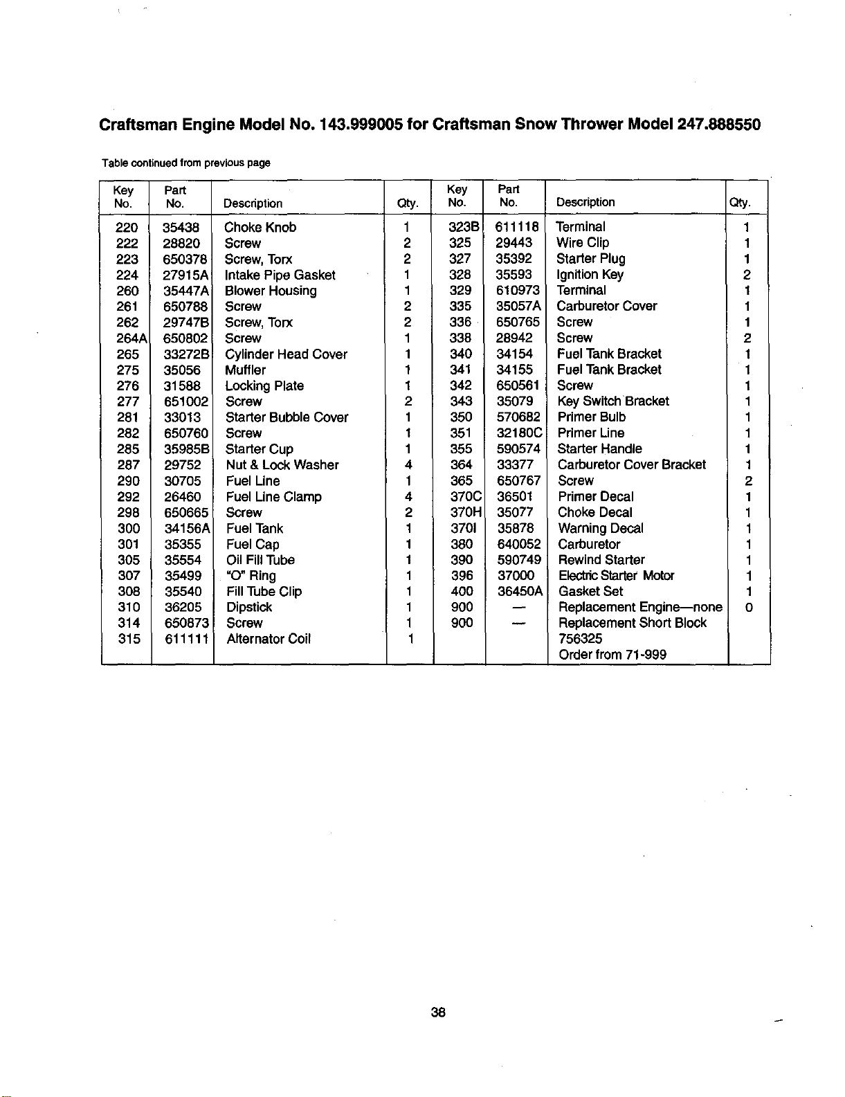
Craftsman Engine Model No. 143.999005 for Craftsman Snow Thrower Model 247.888550
Table continued from previous page
Key Part
No. No.
220 35438
222 28820
223 650378
224 27915A_
260 35447A
261 650788
262 29747B
264A 650802
265 33272B
275 35056
276 31588
277 651002
281 33013
282 650760
285 35985B
287 29752
290 30705
292 26460
298 650665
3OO 34156A
301 35355
305 35554
307 35499
308 35540
310 36205
314 650873
315 611111
Key
Description Qty. No.
Choke Knob 1 323B
Screw 2 325
Screw, Torx 2 327
Intake Pipe Gasket 1 328
BlowerHousing 1 329
Screw 2 335
Screw,Torx 2 336
Screw 1 338
CylinderHead Cover 1 340
Muffler 1 341
LockingPlate 1 342
Screw 2 343
Starter BubbleCover 1 350
Screw 1 351
Starter Cup 1 355
Nut & LockWasher 4 364
Fuel Line 1 365
Fuel LineClamp 4 370C
Screw 2 370H
FuelTank 1 3701
Fuel Cap 1 360
Oil Fill Tube 1 390
=O"Ring 1 396
FillTubeClip 1 400
Dipstick 1 900
Screw 1 900
Alternator Coil 1
Part
No.
611118
29443
35392
35593
610973
35057A
650765
28942
34154
34155
650561
35079
570682
32180C
590574
33377
650767
36501
35077
35878
640052
590749
37000
36450A
Description
Terminal
Wire Clip
Starter Plug
Ignition Key
Terminal
Carburetor Cover
Screw
Screw
Fuel Tank Bracket
Fuel Tank Bracket
Screw
Key Switch Bracket
Primer Bulb
Primer Line
Starter Handle
Carburetor Cover Bracket
Screw
Primer Decal
Choke Decal
Warning Decal
Carburetor
Rewind Starter
ElectricStarter Motor
Gasket Set
Replacement Engine--none
Replacement Short Block
756325
Order from 71-999
Qty,
1
1
1
2
1
1
1
2
1
1
1
1
1
1
1
1
2
1
1
1
1
1
1
1
0
38
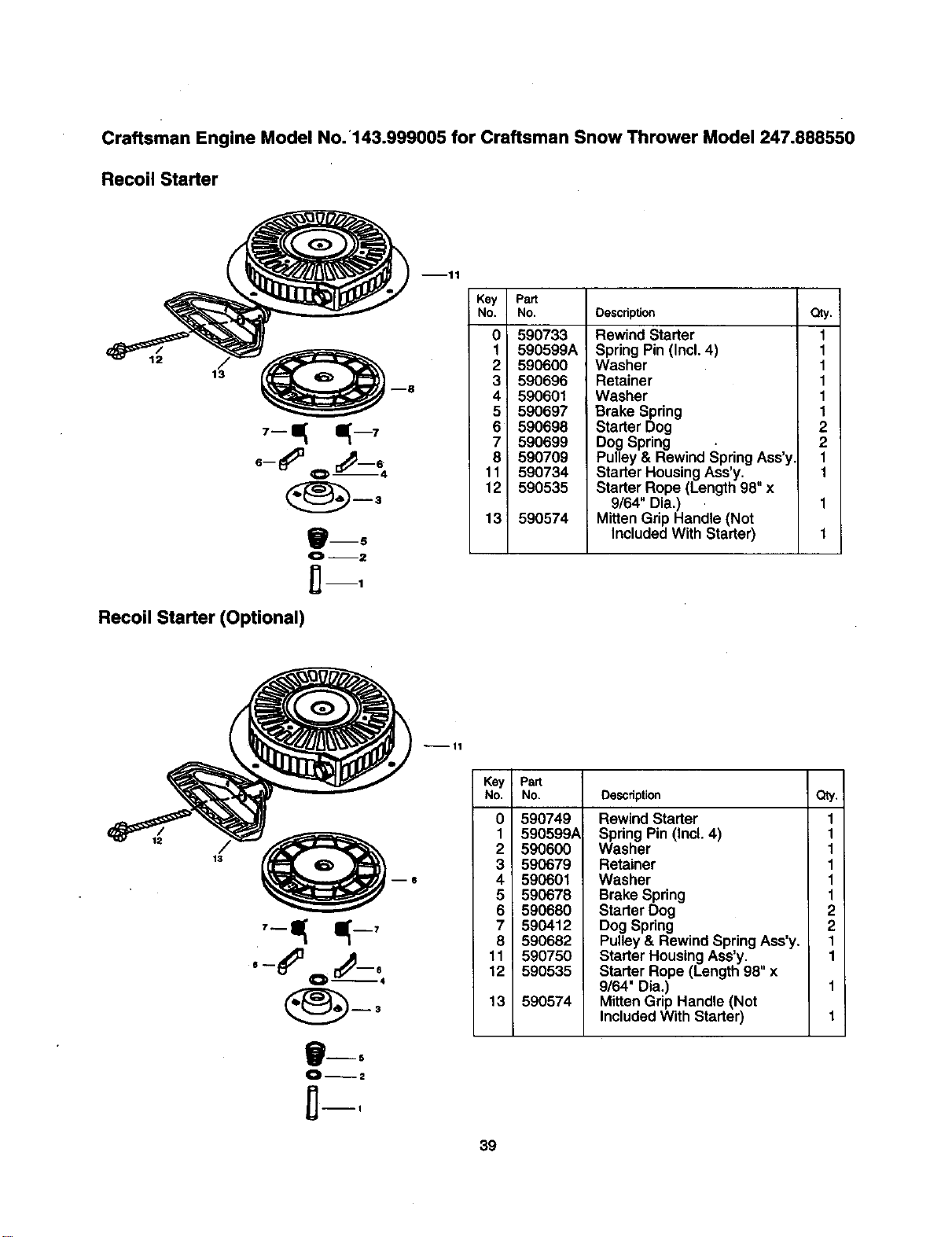
Craftsman Engine Model No. '143.999005 for Craftsman Snow Thrower Model 247.888550
Recoil Starter
12
13
_mS
Recoil Starter (Optional)
mll
Key Pa_
No. No.
0 590733
1 590599A
2 590600
3 590696
4 590601
5 590697
6 590698
7 590699
8 590709
11 590734
12 590535
13 590574
Description
Rewind Starter
SpringPin (Incl. 4)
Washer
Retainer
Washer
Brake Spring
Starter Dog
DogSpring
Pulley& Rewind SpringAss'y
Starter HousingAss'y.
Starter Rope (Length 98" x
9/64" Dia.)
MittenGrip Handle (Not
IncludedWith Starter)
a_.
1
1
1
1
1
1
2
2
1
1
12
°,#-,
B--5
--11
Key , Part
No. No. Description
0
1
2
3
4
5
6
7
8
11
12 _
13
590749
590599A
590600
590679
590601
590678
590680
590412
590682
590750
590535
590574
Qty.
Rewind Starter 1
Spring Pin (Incl. 4) 1
Washer 1
Retainer 1
Washer 1
Brake Spring 1
Starter Dog 2
Dog Spring 2
Pulley& Rewind SpringAss'y. 1
Starter Housing Ass'y. 1
Starter Rope (Length 98" x
9/64" Dia,) 1
MittenGrip Handle (Not
IncludedWith Starter) 1
39

Comments
Date
62
In U.S.A. or Canada
for in-home major brand repair service:
Call 24 hours a day, 7 days a week
1-800-4-MY-HOME sM(1-800-469-4663)
Para pedir servicio de reparaci6n a domiciliio m 1-800-676-5811
Au Canada pour tout le service ou les pi_ces -- 1-800-469-4663
For the repair or replacement parts you need:
Call 6 a.m. -- 11 p.m. CST, 7 days a week
PartsDirect sM
1-800-366-PART (1-800-366-7278)
Para ordenar piezas con entrega a domicillio m 1-800-659-7084
For the location of a Sears Service Center in your area:
Call 24 hours a day, 7 days a week
1-800-488-1222
To purchase or inquire about a Sears Maintenance Agreement:
Call 7 a.m. -- 5 p.m. CST, Monday -- Saturday
1-800-827-6855
p,-
SEARS
HomeCentral""


