ER'S
MANUAL
MODELNO.
247.884410
Caution:
Readand Follow
all Safety Rules
and Instructions
BeforeOperating
This Equipment
CRI:I
MRN
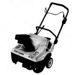
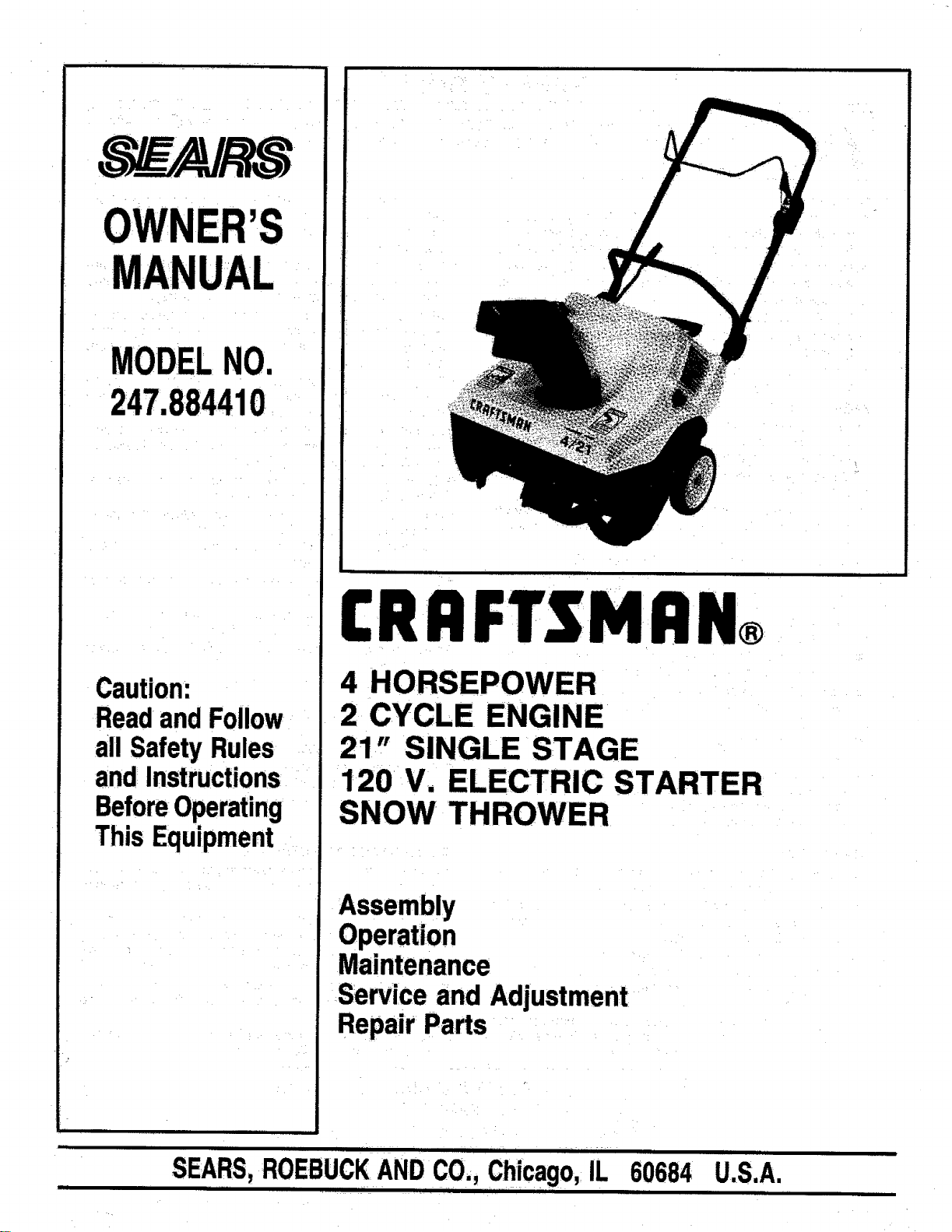
4 HORSEPOWER
2 CYCLE ENGINE
21" SINGLE STAGE
120 V. ELECTRIC STARTER
SNOW THROWER
Assembly
Operation
Maintenance
Service and Adjustment
RepairParts
fr
|.l 11 III I
BUCK hi, IL 60684 U.S.A.SEARS,ROE ANDC0., C cag
O_ .
IIII 1 111 I .... I I111 1 [[I I[ I[[[ [
i
i i ii ii ilul i| iii
SAFETY RULES
, , , I II II III I II I
WARNING: TO REDUCE THE POTENTIAL FOR ANY INJURY, COMPLY WITH THE FOLLOWING
i. FAILURE TO COMPLY WITH THE INSTRUCTIONS MAY RESULT IN
INJURY,
TRAINING
• Readthis owner'sguidecarefully,Beth•roughly familiar
withthe controlsand proper use oftheequipment.Know
howto stopthe unitand disengagethecontrolsquickly.
• Never allow childrento operateequipment.Never allow
adultstooperateequipmentwithoutproperinstructions.
• No oneshouldoperatethisunitwhileintoxicatedorwhile
taking medication that impairsthe sensesor reactions.
• Keeptheareaofoperationclearofall persons;especial-
ly smallchildrenand pets.
• Exercise cautionto avoid slippingor falling, especially
when operatingin reverse,
PREPARATION
• Thoroughlyinspecttheareawherethe equipmentistobe
usedandremovealldoormats,sleds,boards,wires and
otherforeignobjects.
• Disengageall clutchesand shiftintoneutral beforestart-
ing engine.
• Do not operate equipment without wearing adequate
winteroutergarments.Wear footWearwhichwill improve
footing on slipperysurfaces.
• Checkthe fuelbeforestartingtheengine.GaSolineisan
extremelyflammablefuel.Do notfillthefueltankindoors,
whiletheengineisrunning,orwhiletheengineisstillhot:
Replace gasolinecap Securelyand wipe off any spilled
gasolinebeforestartingtheengine as itmay causea fire
or explosion.
• Use a groundedthreewire plug-infor all unitswith elec-
tric drive motorsor electricstartingmotors.
• Never attempttomake any adjustmentswhileengine is
running (except where specifically recommended by
manufacturer).
• Let engine and machineadjustto outdoortemperature
beforestartingto clear snow.
• Alwayswearsafetyglassesor eye shieldsduringopera-
tionor whileperformingan adjustmentor repair,to pro-
tect eyes from foreign objectsthat may be thrownfrom
the machinein any direction.
eStop engine whenever you leave the operating position,
before unclogging the collectodimpeller housing or
discharge guide, and making any repairs, adjustments, or
inspections.
eTake all possible precautions when leaving the unit un-
attended. Disengage the collector/impeller, shift: into
neutral, stop the engine, and remove the key.
• When cleaning, repairing, or inspecting, make certain cot-
lector/impeller and all moving parts have stopped. Discon-
nect spark plug wire and keep away from plug to prevent
accidental starting.
• Do not run engine indoors, except when starting engine
and transporting snow thrower in or out of building. Open
doors. Exhaust fumes are dangerous.
• Do not clear snow across the face of slopes. Exercise
extreme caution when changing direction on slopes. Do
not attempt to clear steep slopes.
• Never operate snow thrower without guards, plates, or
other safety protection devices in place.
• Never operate snow thrower near glass enclosure,
automobiles, window wells, drop off, etc., without proper
adjustments of snow thrower discharge angle. Keep
children and pets away.
• Do not overload machine capacity by attempting to clear
snow at too fast a rate.
• Never operate the machine at high transport speeds on
slippery surfaces. Look behind and use care when backing.
• Never direct discharge at bystanders or allow anyone in
front of unit.
• Disengage power to collectodimpeller when transporting
or not in use.
• Use only attachments and accessories approved by the
manufacturer of snow thrower (such as wheel weights,
counter weights, cabs, etc.).
• Never operate the snow thrower without good visibility or
light; Always be sure of your footing and keep a firm hold
on the handles. Walk, never run.
OPERATION
• Do not puthands or feet near rotatingparts.Keep clear
of dischargeopeningat all times.
• Exerciseextremecautionwhen operatingonor crossing
graveldrives,walks,or roads.Stayalertforhiddenhazards
or traffic.Do notcarry passengers.
• Afterstrikinga foreignobject,stoptheengine,removewire
from sparkplug,andthoroughlyinspectthesnowthrower
for anydamage.Repairthedamagebefore restartingand
operatingthe snowthrower.
• Ifthesnowthrowershouldstarttovibrateabnormally,stop
the engine andcheck immediatelyfor the cause. Vibra-
tion is generaUya warningof trouble,
MAINTENANCE AND STORAGE
• Check shearbolts,enginemounting bolts,etc., atfrequent
intervalsfor propertightnessto be sure equipmentis in
SafewQrkingcondition.
• Never store the machineWithfuel in the fuel tank inside
a buildingwhereignitionsourcesarepresent,suchas hot
waterandspaceheaters,c!Othesdryers, andthelike.Allow
engine to cool beforestoringin anyenclosure.
• Always refer to owner's guide instructionsfor important
details if snow thrower isto be storedfor an extended
periOd.
• Run machine a few:minutesafter throwingsnowto pre-
Ventfreeze up of collect•r/impeller,
LOOK FOR THIS SYMBOL TO POINT OUT
IMPORTANT SAFETY PRECAUTIONS, IT
MEANS--ATTENTION!t!BECOMEALERT.q!
YOUR SAFETY IS INVOLVED=.
CONGRATULATIONS onyourpurchaseofa Sears
CraftsmanSnowThrower.ithasbeendesigned,engineered
andmanufacturedtogiveyouthebestpossibledependability
and performance.
Should you experience any problem you cannot easily
remedy, please contact your nearest Sears Service
Center/Department. We have competent,well-trainedtech-
nicians and the propertools to service or repair this unit.
Plese readand retainthis manual. The instructionswillenable
you to assembleand maintain your snowthrower properly.
Always observe the "SAFETY RULES."
MODEL
NUMBER 247.884410
SERIAL
NUMBER
DATE OF
PURCHASE
THE MODEL AND SERIAL NUMBERS WILL BE FOUND
ON A LABEL ATTACHED TO THE REAR OF THE SNOW
THROWER HOUSING.
YOU SHOULD RECORD BOTH SERIAL NUMBER AND
DATE OF PURCHASE AND KEEP IN A SAFE PLACE
FOR FUTURE REFERENCE.
PRODUCT sPEcIFICATIONS
IIIIIII II I I III I
Horsepower: 4.0
Displacement: 8.46 cu. in.
Fuel Capacity: 2 Quarts
GasotinetOil Mix Ratio: 32:1
(4 oz. of oil per
1 gal. of gas)
Spark Plug (Gap .030 in.): Champion
CJ-8Y or
Equivalent
Solid State Ignition Air Gap: .0125 in,
i iiiiii ii i
MAINTENANCE AGREEMENT
IIII II I I I IIIII I III
A Sears Maintenance Agreement is available on this
product. Contact your nearest Sears store for details.
iii i iiiii i iiiiiiiiiiiiiiii • ii iii iii ii ii iii
CUSTOMER RESPONSIBILITIES
II 11 II1111 IIIII1IIIII11 I1 I ]
• Read and observe the safety rules.
• Follow a regular schedule in maintaining, caring for and using your snow thrower.
: • Follow the instructions under "Maintenance" and "Storage" sections of this Owner's Manual.
ii ii i
iiirrlri i
IIIIIII111111III IIIIIIIIIIIIIIIIIIIIII IIIIIIIIII I
WARRANTY
III IIIIIIIIIIIIIIIIIIIIIIIII1II I II IIII I I Ilrr
ONEYEARLIMITEDWARRANTYONCRAFTSMANSNOWTHROWER
For one year from the date of purchase, when this Craftsman Snow Thrower is maintained, lubricated and tuned-
up according to the instructions in the owner's manual, Sears will repair, free of charge, any defect in material
and workmanship.
If this Craftsman Snow Thrower is used for commercial or rental purposes, this warranty applies for only 30
days fromthe date of purchase. ..... _ . _
This warranty does not cover:
. Expendable:items which become worn during normal, use, such as scraper bars, belts and spark plugs.
,e Repairs necessary because of operator abuse or negligence, including bent crankshafts and the failure to
maintain the equipment according to the instructions contained in the owner's manual.
WARRANTY SERVICE iS.AVAILABLE BY RETURNING THE CRAFTSMAN SNOW THROWER TO THE
NEAREST SEARS SERVtCE CENTERIDEPARTMENT IN THE UNITED STATES:THIS WARRANTY APPLIES
ONLY WHILE THIS PRODUCT IS IN USE IN THE UNITED STATES.
This warranty gives you specific legal rights, and you may also have other rights which may vary from state
to state.
SEARS, ROEBUCK AND CO. Department 731CR-W Sears Tower, Chicago, IL 60684
3
it i LI ittl t
TABLE OF CONTENTS
ii ii i tt t lit ttttt L ..i
SAFETY RULES .............................. 2 _
PRODUCT SPECIFICATIONS .................. 3
CUSTOMER RESPONSIBILITIES ............... 3
WARRANTY ................................. 3
INDEX ..................................... 4
SNOW THROWER ACCESSORIES ...... _....... 4
ASSEMBLY ........... ........................ 5
OPERATION ............................... 6
MAINTENANCE ................................ 9
STORAGE ...................................... 10
SERVICE AND ADJUSTMENT .................. 11
SERVICE RECOMMENDATIONS .............. 12
TROUBLE SHOOTING. ..................... _.... 13
REPAIR PARTS--SNOW THROWER .......... 14
REPAIR: PARTS--ENGINE, ....... ............ 16
PARTS ORDERING/SERVICE ........ Back Cover-
tt i i
INDEX
t t it t
A
Adjustments:
Carburetor ................................ -11
Discharge Chute .............................. 7
Engine Speed .............................. 11:
Assembly Instructions:
Chute Crank ................................ 5
Control Cable .............................. 5
Accessories .................................... ..... 4
B
Belts:
RemovaltReplacement ...................... 11
Tension Adjustment .................. •.......... 9
C:
Controls: .................................... 6
Customer Responsibilities .................... 3
E
Electric Starter ............................ 6, 8
Engine:
Maintenance ............................... 9
Starting ..................................... 8
Stopping ................................. 8
Storage ..................... r.............. 10
F
Fuel Mixture .................................. 7
M
Maintenance:
Agreement ................................. 3
Engine ..................................... 9
Snow Thrower .......... "................... 9
O
Operating Tips ................................. 9
P
Primer ...................................... 6, 8
R
RepairlReplacement Parts ..................... 16
Responsibilities, Customer. ......................... 3
S
Safety Rules ................................ 2
Shave Plate ................................ 11
Service Recommendations .................... 12
.Spark P!ug ...................................... ,9
Specifications .................................. 3
Storage . ................................... 10
T
Table of Contents ............................ 4
Trouble Shooting ............................ 13
W
Warranty ............................. ....... 3
L
Lubrication ................................. 9
i qllUllli r] ii i]1111H] III r
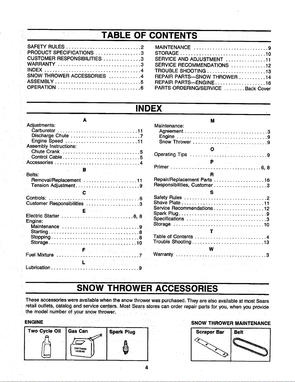
SNOW THROWER ACCESSORIES
These accessories were available when the snow thrower was purchased. They are also available atmost Sears
retail outlets, catalog and service centers. Most Sears stores can order repair parts for you, when you provide
the model number of your snow thrower.
ENGINE
Two Cycle Oil I Gas Can ! Spark Plug
I
!
Gi$01k_{
SNOW THROWER MAINTENANCE
4
._ iiiiii HLI III IIII I
iii i i iiii iJl ..... IL,,,,,,,,,,IIIIIII,IIIIIIi
FIGURE 1.
mllll ,vl I I IIII .... Ill
ASSEMBLY
I IIIIII II I II I IIIIIIII III
Knob
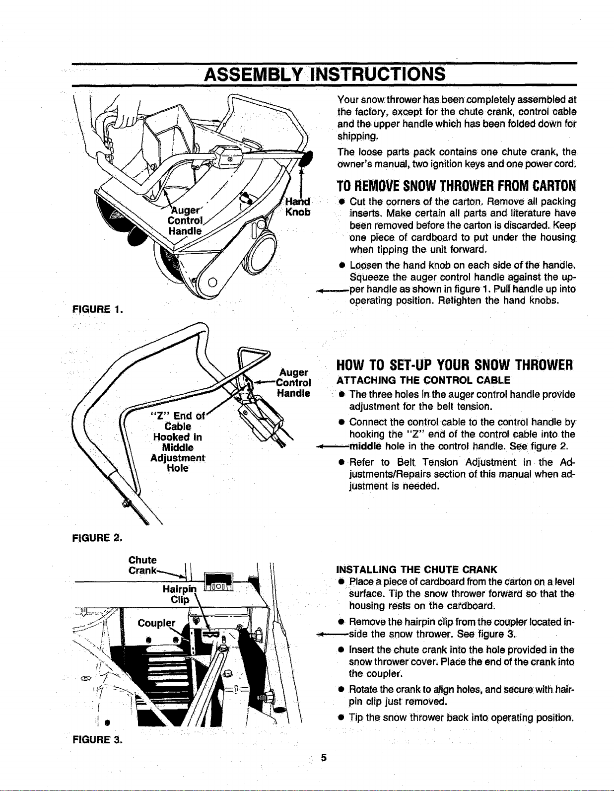
Your snow thrower has been completely assembled at
the factory, except for the chute crank, control cable
and the;upper handle which has been folded down for
shipping,
The loose parts pack contains one chute crank, the
Owner's manual,_two ignition keys and one power cord:
TOREMOVESNOWTHROWERFROMCARTON
• Cut the corners of the carton, Remove all packing
inserts. Make certain all parts and literature have
been removed before the carton is discarded, Keep
one piece of cardboard to put under the housing
when tipping the unit forward,
• Loosen the hand knob on each side of the handle_
Squeeze the auger control handle against the up-
-_--.--per handle as shown in figure 1. Pull handle up into
operating position. Retighten the hand knobs.
__'__ Auger
HOWTOSET-UPYOURSNOWTHROWER
ATTACHING THE CONTROL CABLE
e. The three holes inthe auger control handle provide
adjustment for the belt tension.
• Connect the control cable to the control handle by
hooking the "Z" end of the control cable into the
-*---.-middle hole in the control handle. See figure 2.
• Refer to Belt Tension Adjustment in the Ad-
justments/Repai rs section of this manual when ad-
justment is needed.
FIGURE 2.
, !
FIGURE 3.
Chute
Crank_ 1
Hairpin _
/
INSTALLING THE CHUTE CRANK
• Place a piece ofcardboard from the carton on a level
surface. Tip the snow thrower forward so that the
housing rests on the cardboard;
o Remove the hairpin clipfrom the coupler located in-
-._-_--side the snow thrower. See figure 3.
• Insert the chute crank into the hole provided in the
snow thrower cover. PlaCe the end ofthe crank into
the coupler.
• Rotatethe crank toalign holes, and secure with hair-
pin c!ip just removed,
• Tip the snow thrower back into operating position.
5
i i t i ,la t t t t t t
OPERATION
IIII II II II II I I I
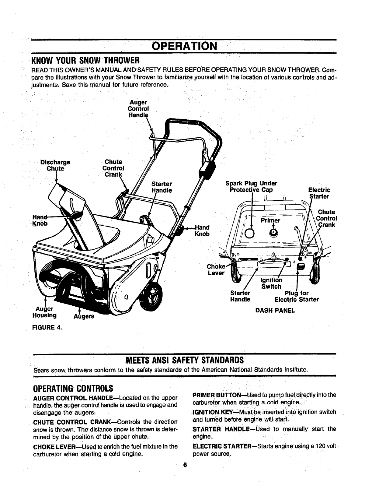
KNOWYOURSNOWTHROWER
READ THiS OWNER'S MANUAL AND SAFETY RULES BEFORE OPERATING YOUR SNOW THROWER, Com-
pare the illustrations with your Snow Thrower to familiarize yourself with the location of various controls and ad-:
justments. Save this manual for future reference.
Auger
Control
Handle
Discharge Chute
Chute Control
Cran
: !Knob '
Auger
Housing
FIGURE 4.,
ers
Starter
Handle
111111 11111 iiii 111111111
MEETSANSISAFETYSTANDARDS:
Sears Snow throwers conform to:the safety:standards of:the :American National Standards Institute:
I III IIIIIIIIIIIIIIIIIII IIIIIIIII I I....... I
OPERATINGCONTROLS :
AUGER CONTROL HANDLE--Located on the upper PRIMER BUTTON--USed to pump fuel directly,intothe
handle, the auger controlhandle is used to engage and carburetor :when starting a:coid engine. :
disengage the: augers. IGNITION KEY_iusti:be inserted into:ignition switch
CHUTE CONTROL CRANK--Controls; the direction
snow is thrOWn,The distance snow is thrown isdeter-
mined by the position of the upper chute;
CHOKE,LEVER--Used toenrichthe fuel mixtureinthe
carburetor' when starting a cold engine_
and turned before engine wilJ start;:
:STARTER: HANDLE--USed to manually sta:rt the
engine. ;
ELECTRIC STARTER--Starts engine' using a 120 volt,
power source,
OPERATION
III III II II I III I IIIIIIIII I I IIIIIIII II I I I IIIlllllll IIIII I I
BEFORE USING YOUR SNOW THROWER, AGAIN REFER TO THE "SAFETY RULES" AS SHOWN ON PAGE
2 OF THIS MANUAL, ALWAYS BE CAREFUL.
The operation of any snow thrower can result in foreign objects being thrown intothe
eyes, which can result in severe eye damage. Always wear safety glasses or eye shields
before starting power toot operation or while performing any adjustments or repairs.
We recommend Wide Vision Safety Mask for over spectacles or standard glasses
available at Sears Retail or Catalog Stores.
HOWTO USEYOURSNOWTHROWER
AUGER CONTROL HANDLE
The snow thrower is propelled by the rotation of the
augers.
• Pull the control handle back against the upper han-
dle to engage the augers and drive the unit forward.
• Push downward on the handle to raise the augers
off the ground and stop the forward motion.
• Release the control handle to stop the augers. To
stop the engine, turn ignition key to OFF position.
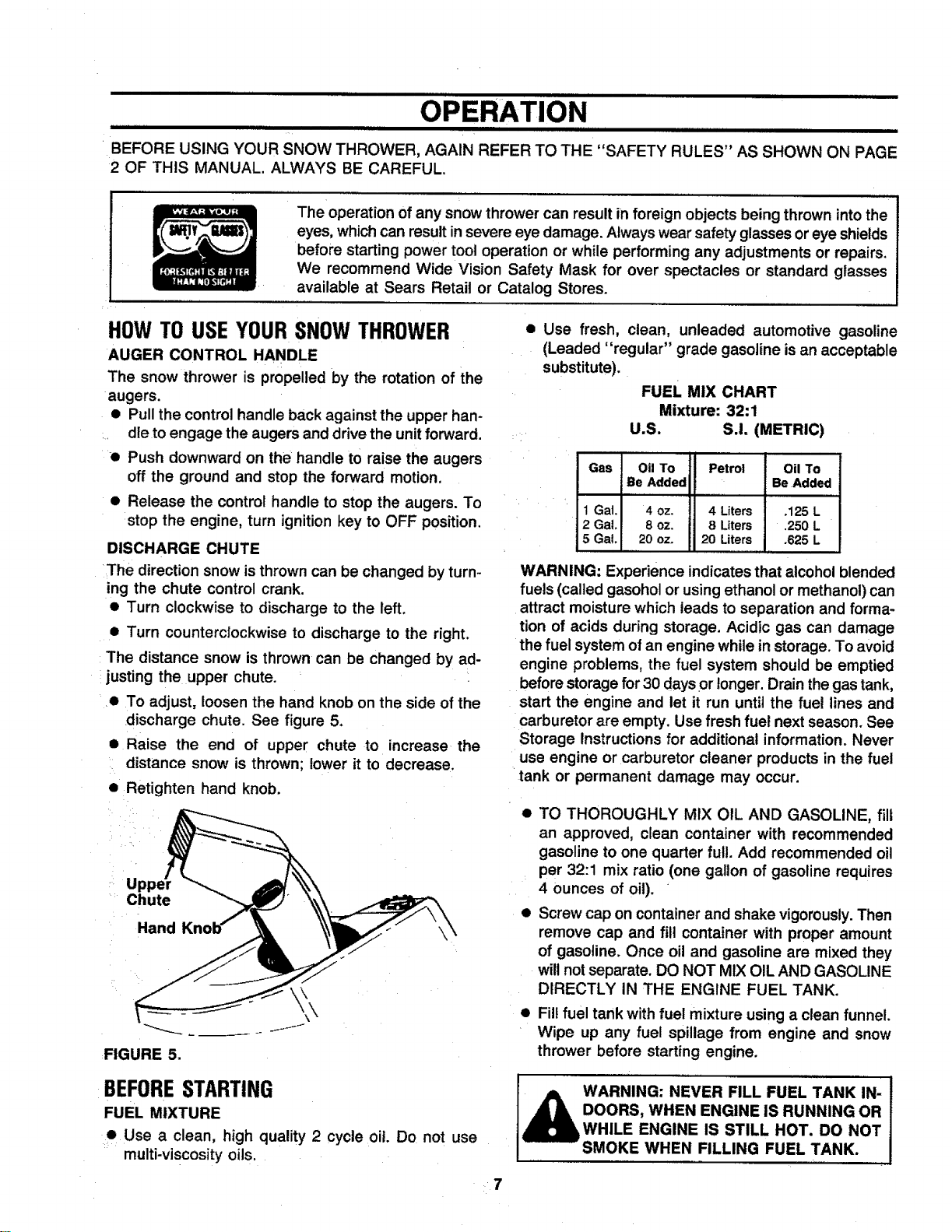
DISCHARGE CHUTE
The direction snow is thrown can be changed by turn-
ing the chute control crank.
• Turn clockwise to discharge to the left.
• Turn counterclockwise to discharge to the right.
The distance snow is thrown can be changed by ad-
justing the upper chute.
• To adjust, loosen the hand knob on the side of the
discharge chute. See figure 5+
• Raise the end of upper chute to increase the
distance snow is thrown; lower it to decrease.
• Retighten hand knob.
+ U
Chute
Hand
FIGURE 5.
BEFORESTARTING
FUEL MIXTURE
Use a clean, high quality 2 cycle oil Do not use
multi-viscosity oils.
•7
• Use fresh, clean, unleaded automotive gasoline
(Leaded "regular" grade gasoline isan acceptable
substitute).
FUEL MIX CHART
Mixture: 32:1
U.S. S.I. (METRIC)
Gas Oil To Petrol Oil To
Be Added Be Added
t Gal. 4 oz. 4 Liters .125L
2 Gal. 8 oz. 8 Liters .250L
5 Gal+ 20oz+ 20 Liters .625L
WARNING: Experience indicates that alcohol blended
fuels (called gasohol or using ethanol or methanol) can
attract moisture which leads to separation and forma-
tion of acids during storage. Acidic gas can damage
the fuel system of an engine while in storage. To avoid
engine problems, the fuel system should be emptied
beforestorage for30 daysor longer. Drain the gas tank,
start the engine and let it run until the fuel lines and
carburetor are empty. Use fresh fuel next season. See
Storage Instructions for additional information. Never
use engine or carburetor cleaner products in the fuel
tank or permanent damage may occur.
• TO THOROUGHLY MIX OIL AND GASOLINE, fill
an approved, clean container with recommended
gasoline to one quarter full. Add recommended oil
per 32:1 mix ratio (one gallon of gasoline requires
4 ounces of oil).
• Screw cap on container and shake vigorously. Then
remove cap and fill container with proper amount
of gasoline. Once oil and gasoline are mixed they
will not separate. DO NOT MIX OIL AND GASOLINE
DIRECTLY IN THE ENGINE FUEL TANK.
Fill fuel tank with fuel mixture using a clean funnel.
Wipe up any fuel spillage from engine and snow
thrower before starting engine.
WARNING: NEVER FILL FUEL TANK IN- J
DOORS, WHEN ENGINE IS RUNNING OR
WHILE ENGINE IS STILL HOT. DO NOT
SMOKE WHEN FILLING FUEL TANK.
i i . ill i i i.= . .i , ,
OPERATION
i i i i
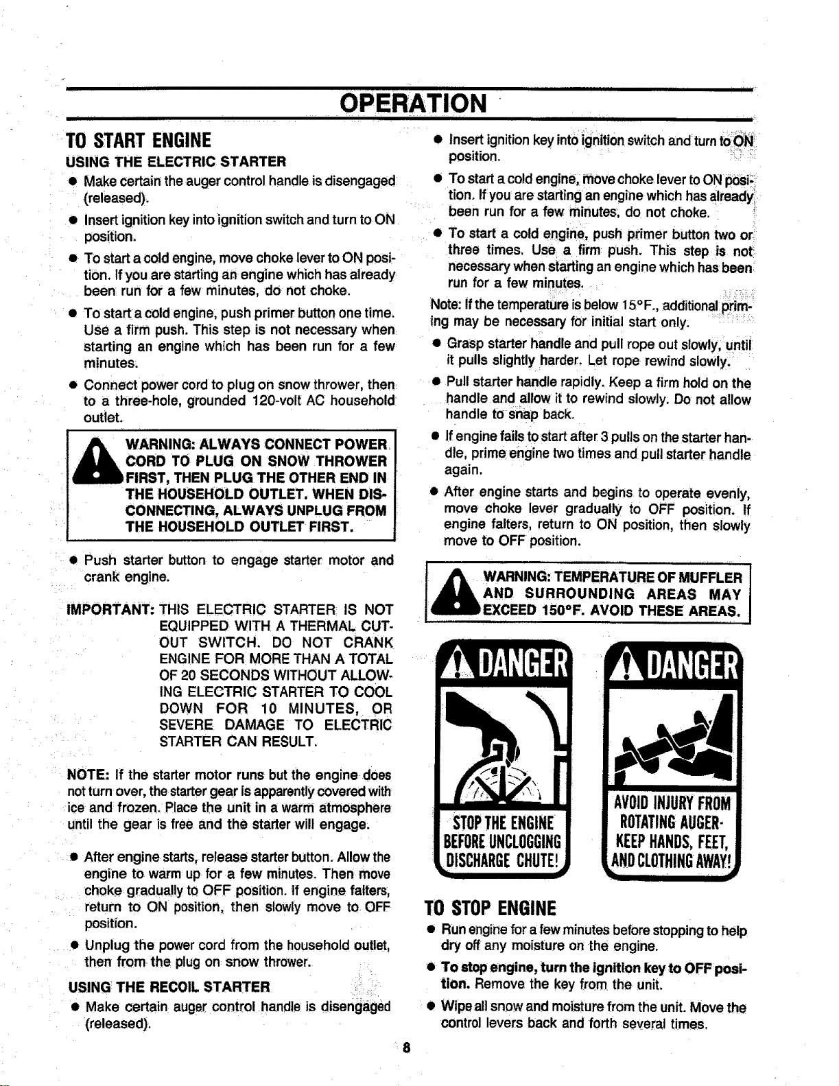
TOSTARTENGINE
USING THE ELECTRIC STARTER
• Make certain the auger control handle is disengaged
(released).
• Insert ignition key into ignition switch and turn to ON
position.
• To start a cold engine, move choke lever to ON posi-
tion. If you are starting an engine which has already
been run for a few minutes, do not choke.
• To starta cold engine, push primer button one time.
Use a firm push. This step is not necessary when
starting an engine which has been run for a few
minutes:
• Connect power cord to plug on snow thrower, then
to a three-hole, grounded 120-volt AC household
outlet.
ALWAYS CONNECT POWER
TO PLUG ON SNOW THROWER
THEN PLUG THE OTHER END IN
THE HOUSEHOLD OUTLET, WHEN DIS-
CONNECTING, ALWAYS UNPLUG FROM
THE HOUSEHOLD OUTLET FIRST.
• Push starter button to engage starter motor and
crank eng] he.
IMPORTANT: THIS ELECTRIC STARTER IS NOT
EQUIPPED WITH A THERMAL CUT-
OUT SWITCH. DO NOT CRANK
ENGINE FOR MORE THAN A TOTAL
OF 20 SECONDS WITHOUT ALLOW-
ING ELECTRIC STARTER TO COOL
DOWN FOR 10 MINUTES, OR
SEVERE DAMAGE TO ELECTRIC
STARTER CAN RESULT.
NOTE: If the starter motor runs butthe engine does
notturn over, the startergear is apparentlycovered with
ice and frozen. Place the unit in a warm atmosphere
until the gear is free and the starter will engage.
• After engine starts, release starter button. Allow the
engine to warm up for a few minutes. Then move
choke gr;adua!lytOOFF position.If engine falters,
return to QN position, then slowly move to OFF
position.
• Unplug the power cord from the household outlet,
then from the plug on snow thrower.
USING THE RECOIL STARTER :
• Make certain auger control handle is disengaged
(released).
• Insert ignitionkey intoignitionswitchandturn to0N I
position.
• To start a coldengine, move choke lever to ON poSi:i_
tion. Ifyou are starting an engine which has already
been run for a few minutes; do not choke.
• To start a cold engine, push primer button two or
three times, Use a firm push. This step is not
necessary when starting an engine which hasbeen
run for a few minutes.
Note: Ifthe temperature isbelow 15° F., additionalp_im-
ing may be necessary for initial start only:
• Grasp starter handle and pull rope out slowly, until
it pulls slightlyharder. Let rope rewind slowly.
• Pull starter handle rapidly. Keep a firm hold on the
handle and allow it to rewind slowly. Do not allow
handle to snap back.
• If engine fails tostart after 31pulls on thestarter han-
dle, prim•engine two times and pull starter handle
again.
After engine starts and begins to operate evenly,
move choke lever gradually to OFF position, tf
engine falters, return to ON position, then slowly
move to OFF position.
_ ARNING: TEMPERATURE OF MUFFLER 1
AND SURROUNDING AREAS MAY
_EXCEED 150=F. AVOID THESE AREAS.
AVOIDINJURYFROM
ROTATINGAUGER-
KEEPHANDS,FEET,
ANDCLOTHINGAWAY
lu.
TOSTOPENGINE
• Run engine for a fewminutes before stoppingto help
dry off any moisture on the engine.
• To stop engine, turn the ignition key to OFF posi-
tion. Remove the key from the unit.
• Wipe all snow and moisture from the unit. Move the
control levers back and forth several times.
8
||Ill [ I L L
OPERATINGTIPS
• Use your snow thrower to remove fresh snow before
it is packed down by footprints or tire tracks.
• Discharge snow in the direction the wind is blowing
whenever possible.
• Slightly overlap each previous swath.
• Snow up to about an 8 inch depth can be removed
easily by walking at a moderate rate. Slow your pace
for wet or deep snow.
• Run engine for a few minutes before stopping tohelp
dry off any moisture on the engine.
MAINTENANCE ..........
I i I I I III I
GENERALRECOMMENDATIONS
• Periodically check all fasteners and be sure they are
tight.
• Follow the Service Recommendation Schedule on
page 12.
SNOWTHROWER
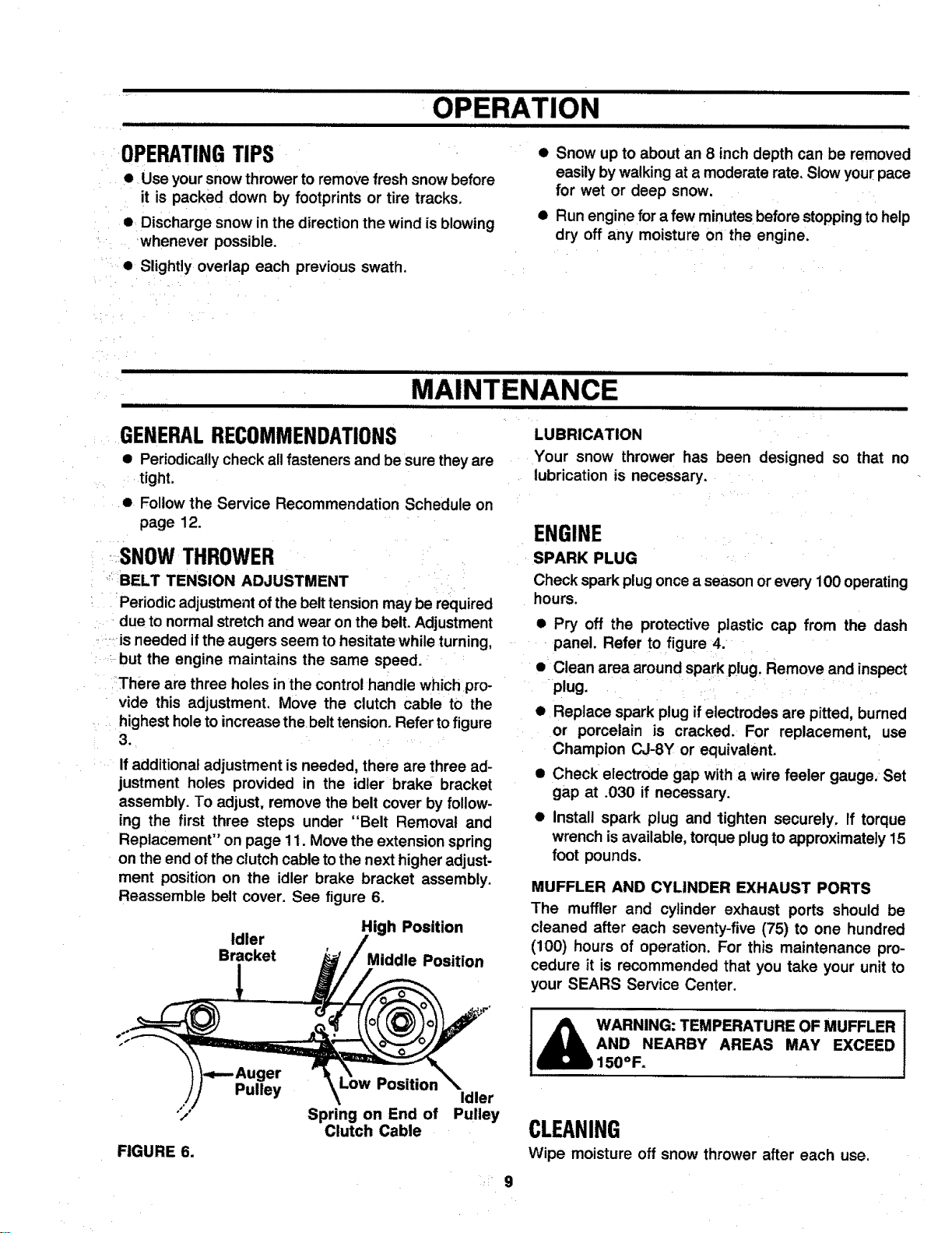
BELT TENSION ADJUSTMENT
Periodicadjustment of the belt tension may be required
due tonormal stretch and wear on the belt. Adjustment
is needed ifthe augers seem to hesitate white turning,
but the engine maintains the same speed.
There are three holes in the controlhandle which pro-
vide this adjustment. Move the clutch cable to the
highest holeto increase the belt tension. Refer tofigure
3.
Ifadditional adjustment is needed, there are three ad-
justment holes provided in the idler brake bracket
assembly. To adjust, remove the belt cover by follow-
ing the first three steps under "Belt Removal and
Replacement" on page 11. Move the extension spring
on the end of the clutch cable tothe next higher adjust-
ment position on the idler brake bracket assembly.
Reassemble belt cover. See figure 6.
High Position
Idler
Bracket Middle Position
LUBRICATION
Your snow thrower has been designed so that no
lubrication is necessary.
ENGINE
SPARK PLUG
Check spark plug once a season or every 100 operating
hours.
• Pry off the protective plastic cap from the dash
panel. Refer to figure 4.
• Clean area around spark plug. Remove and inspect
plug,
• Replace spark plug ifelectrodes are pitted, burned
or porcelain is cracked. For replacement, use
Champion CJ-SY or equivalent.
• Check electrode gap with a wire feeler gauge. Set
gap at .030 if necessary.
Install spark plug and lighten securely, If torque
wrench is available, torque plug to approximately 15
foot pounds.
MUFFLER AND CYLINDER EXHAUST PORTS
The muffler and cylinder exhaust ports should be
cleaned after each seventy-five (75) to one hundred
(100) hours of operation. For this maintenance pro-
cedure it is recommended that you take your unit to
your SEARS Service Center.
/
FIGURE 6.
Pulley
Position
Idler
Spring on End of Pulley
Clutch Cable
WARNING: TEMPERATURE OF MUFFLER J
AND NEARBY AREAS MAY EXCEED
,1500F.
CLEANING
Wipe moisture off snow thrower after each use.
9
ii ...................
STORAGE
II I I iii IIIIIIIIII I I I I I II
Your snow thrower and engine should be prepared for
off-season storage as follows.
SNOWTHROWER
• Thoroughly clean the snow thrower.
• If storing in an unventilated or metal storage shed,
coat any metal parts with a lightoil or siliconeto pre-
vent rust.
• Block the unit up so that it is not resting on the
rubber augers.
• Store in a clean, dry area.
HANDLE
The upper handle on your snow thrower may be folded
down for storage.
• Place the upper chute in the positionshown in figure
1. Loosen the handknob and pivotthe chute upward
to its highest position. Use the chute crank to turn
it tothe side.
• Loosen the hand knobs on the side of the handle.
Push the upper handle forward and down, Be careful
not to bend or kink the cable.
ENGINE
WARNING: NEVER STORE ENGINE WITH
FUEL IN TANK INDOORS OR ENCLOSED,
IN POORLY VENTILATED AREAS WHERE
FUMES MAY REACH AN OPEN FLAME,
SPARK OR PILOT LIGHT SUCH AS ON A
FURNACE, WATER HEATER, CLOTHES
DRYER OR OTHER GAS APPLIANCE.
IMPORTANT: IT IS IMPORTANT TO:PREVENT GUM
DEPOSITS FROM FORMING IN
ESSENTIAL FUEL SYSTEM PARTS
SUCH AS THECARBURETOR, FUEL
HOSE OR FUEL TANK DURING
STORAGE. ALSO, EXPERIENCE IN,
DICATES THAT ALCOHOL BLENDED
FUELS (CALLED GASOHOL OR
USING ETHANOL OR METHANOL)
CAN ATTRACT MOISTURE WHICH
LEADS TO SEPARATION AND
FORMATION OF ACIDS DURING
STORAGE. ACIDIC GAS ! CAN
DAMAGE THE FUEL SYSTEM OF AN
ENGINE WHILE IN STORAGE.
• Run engine until fuel tank is empty andengine stops
due to lack of fuel.
• Disconnect fuet line at carburetor or fuel tank. Be
careful not to damage fuel line, fittings or fuel tank.
Drain any remaining fuel from the system.
_b ARNING: DRAIN FUEL INTO APPROVED
CONTAINER OUTDOORS, AWAY FROM
OPEN FLAME.
NOTE: If gasohol has been used, complete the
preceding instructions. Then put a small amount, one
pint or less, of unleaded (or regular) grade gasoline
properly mixed with oil per Fuel Mix Chart on page 7.
Repeat the two above steps.
• Pull starter handle out slowly until it pulls slightly
harder. Let rope rewind slowly. This procedure will
close both the intakeand exhaust ports, to prevent
corrosion of the piston and cylinder bore.
10
.......................................................SERVICE &ADJUSTME"'''"""..... .........
ii I iiiiiiiiiiiiiiiiiiiiiii ill III iiiiiiiiiiiiiiiiiiiiiiII III I I iiiiiiiuiiiiiiiiiiiiii I II I
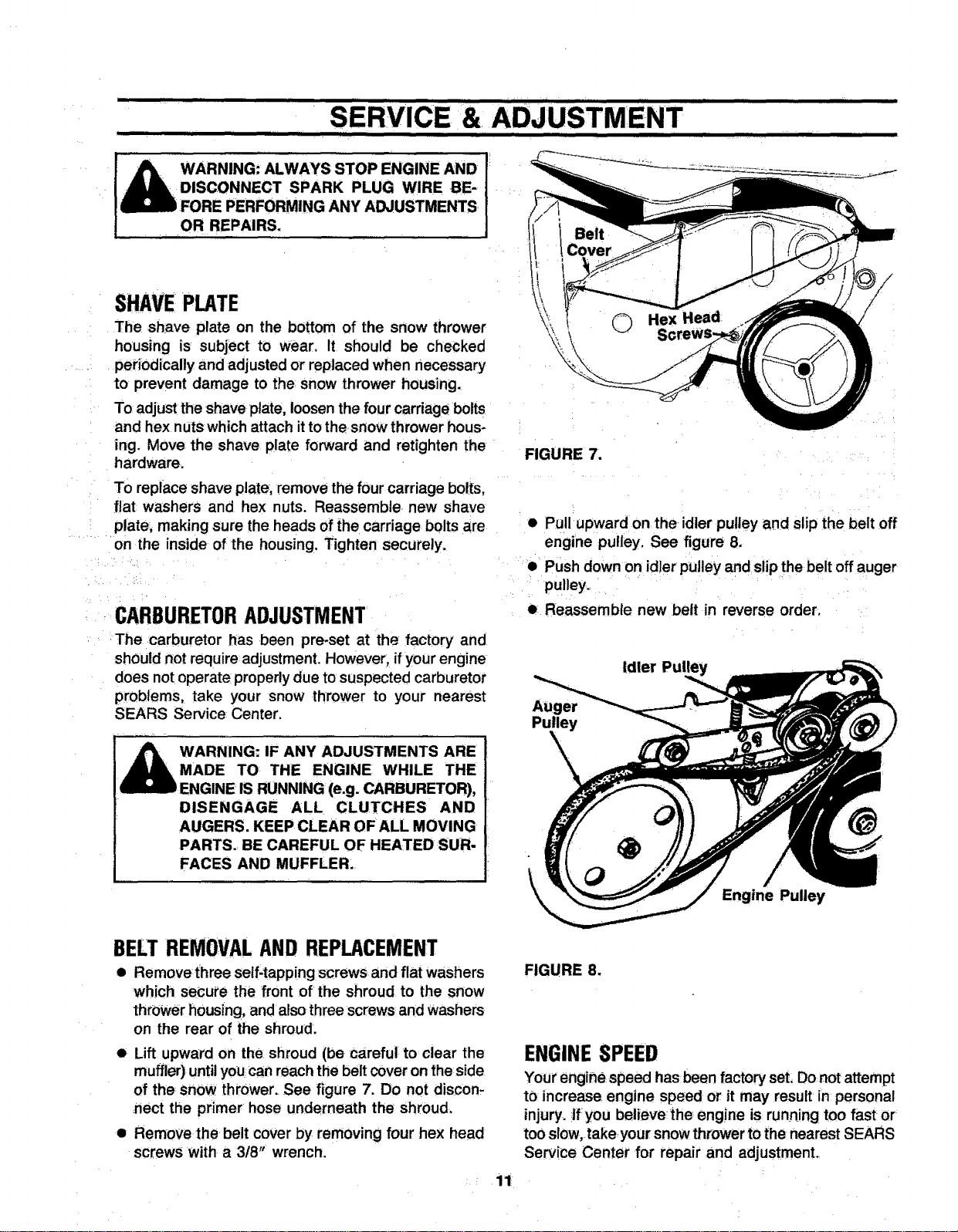
[ _1_ WARNING: ALWAYS STOP ENGINE AND [:
_:DISCONNECT SPARK PLUG WIRE eE-
gmzmlD FORE PERFORMING ANY ADJUSTMENTS
OR REPAIRS.
SHAVEPLATE
The shave plate on the bottom of the snow thrower
housing is subject to wear. It should be checked
periodically and adjusted or replaced when necessary
to prevent damage to the snow thrower housing.
To adjust the shave plate, loosen the four carriage bolts
and hex nuts which attach it to the snow thrower hous-
ing. Move the shave plate forward and retighten the
hardware.
To replace shave plate; remove the four carriage bolts,
flat washers and hex nuts. Reassemble new shave
plate; making sure the heads of the carriage bolts are
on the inside of the housing. Tighten securely.
CARBURETORADJUSTMENT
The carburetor has been pre-set at the factory and
should not require adjustment. However, if your engine
does not operate properly due to suspected carburetor
problems, take your snow thrower to your nearest
SEARS Service Center.
A WARNING: IF ANY ADJUSTMENTS ARE
A MADE TO THE ENGINE WHILE THE
ENGINE IS RUNNING (e.g. CARBURETOR),
DISENGAGE ALL CLUTCHES AND
AUGERS. KEEP CLEAR OFALL MOVING
PARTS. BE CAREFUL OF HEATED SUR-
FACES AND MUFFLER.
FIGURE 7,
• PuU upward on the idler pulley and slip the belt off
engine pulley. See figure 8.
• Push down on id]er pulley and slip the belt off auger
pulley.
• Reassemble new belt in reverse order.
Idler
Auger
Pulley
Engine Pulley
BELTREMOVALANDREPLACEMENT
• Removethree self-tapping screws and flat washers
which secure the front of the shroud to the snow
thrower housing, and also three screws and washers
on the rear of the shroud.
• Lift upward on the shroud (be careful to clear the
muffler)until you can reach the belt cover on the side
of the snow thrower. See figure 7. Do not discon-
nect the primer hose underneath the shroud.
• Remove the belt cover by removing four hex head
screws with a 3/8": wrench.
FIGURE 8.
ENGINE SPEED
Your engine, speed has been factory seL Do not attempt
to increase engine speed or it may result in personal
injury, ffyou believe;the engine is, running too fast Or
too slow, take,your snow thrower to the nearest SEARS
Service Center for repair and adjustment.
, 11
iiii N iiim.... RECOMMENDATIO S
iii i1|1 i i I I IIII I lU II I
SERVICERECORD
Fill in dates as you ......
complete regular service
Check: Fuel
Drain Fuel
Tighten All Bolts and Nuts
Adjust Belt Tension
Check Spark Plug
Clean Muffler & Cylinder
Exhaust Ports
SCHEDULE
First Fre- Every
2 quently 25
Hours Use Hours
....,, • • , ....
Every Begin;
75 to 100 ning Each
Hours Season
| , • ,,
Before
iStorage
SERVICEDATES
J
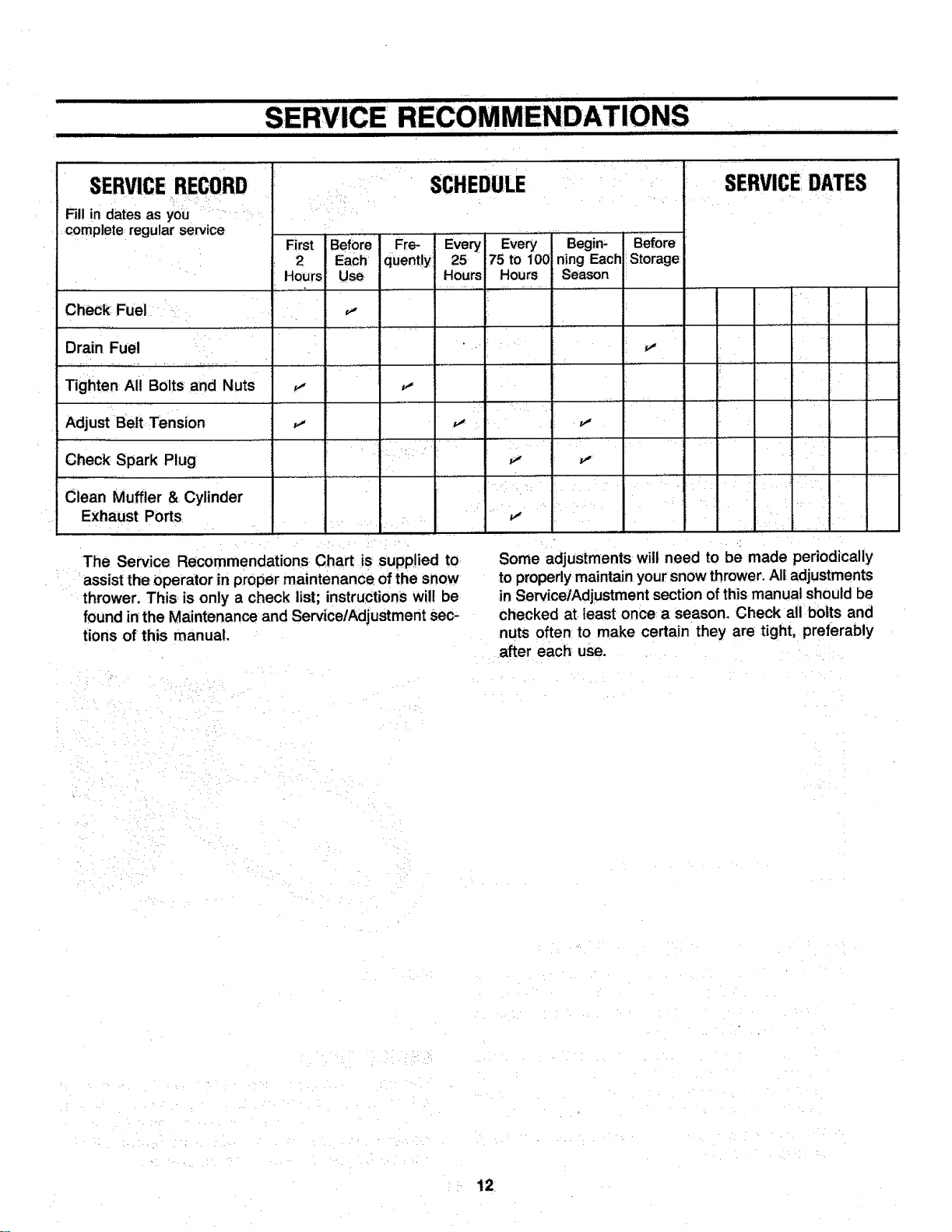
The Service Recommendations Chart is supplied to
assist the operator in proper maintenance of the snow
thrower. This is only a check list; instructions will be
found in the Maintenance and ServicelAdjustment sec-
tions of this manual.
i
Some adjustments will need to be made periodically
to properly maintain your snow thrower. All adjustments
in ServicelAdjustment section of this manual should be
checked at least once a season. Check all bolts and
nuts often to make certain they are tight, preferably
after each use.
12
TROUBLE SHOOTING
. llll i i i i . i
POSSIBLE CAUSE(S)
PROBLEM
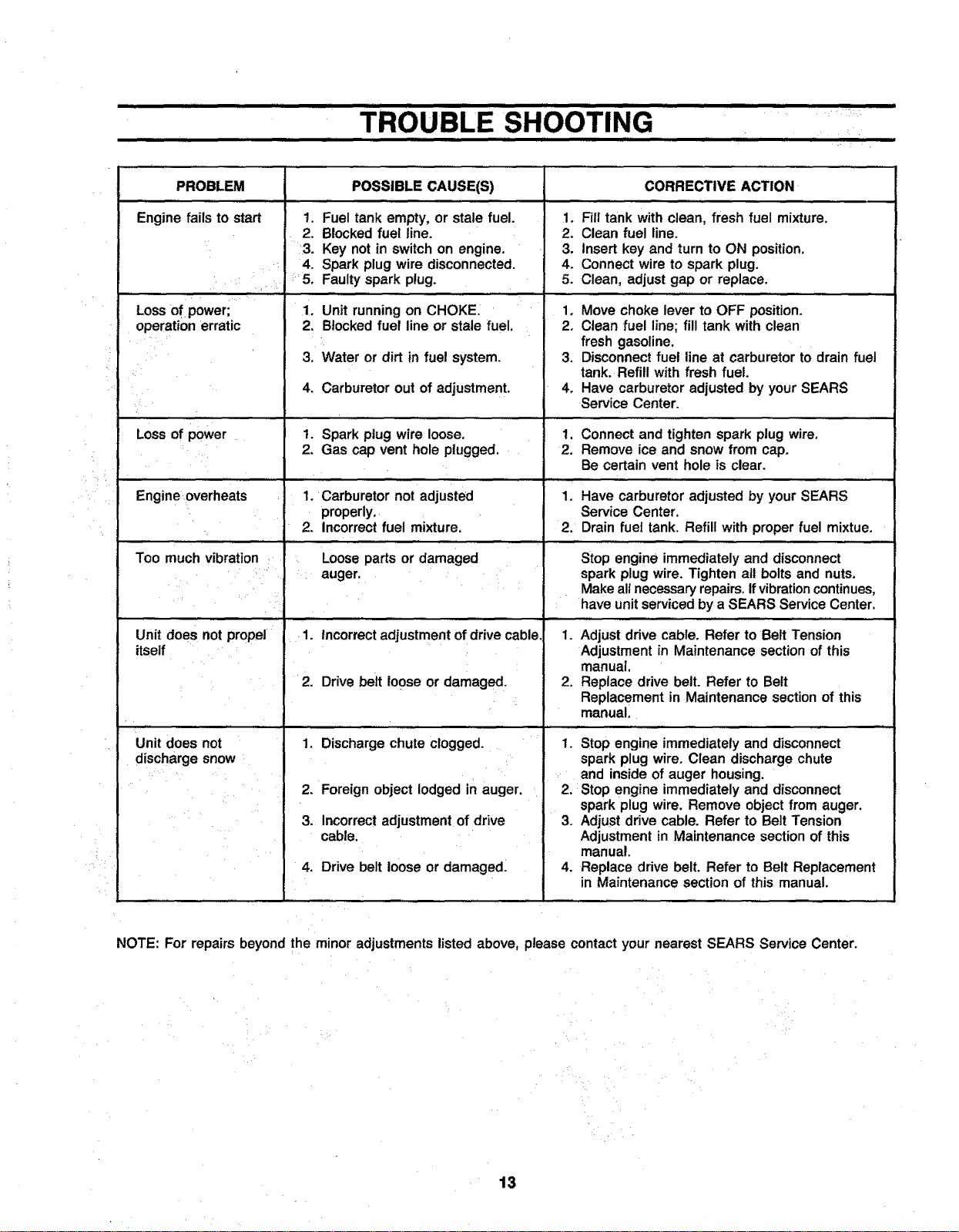
Enginefails to start
Lossof power;
operation erratic
LOSSof power
Engine overheats
, , L .....
Too muchvibration
1.
2.
• ••1 •4.
•1•.
2.
3.
4,
Fuel tank empty, or stale fuel.
Blocked fuel line.
Key not in switchon engine.
Spark plug wire disconnected.
Faultyspark plug.
Unitrunning on CHOKE.
Blockedfuel line or stale fuel,
Water or dirt in fuel system.
Carburetor out of adjustment.
1. Spark plug wire loose.
2. Gas cap vent hole plugged.
1. Carburetor not adjusted
properly,
2. Incorrectfuel mixture,
.... j,,,
Looseparts or damaged
" auger.
Unit does not propel
itself
Unit does not
discharge snow
1. incorrect adjustment of drivecable,
2. Drive belt loose or damaged.
1. Discharge chute clogged.
2. Foreign object lodged in auger.
3. Incorrectadjustmentof drive
cable.
4. Drive belt loose or damaged.
CORRECTIVE ACTION
1. Fill tank with clean, fresh fuel mixture,
2. Clean fuel line.
3. Insert key and turn to ON position.
4. Connectwire to spark plug.
5. Clean, adjustgap or replace.
,, , J , ,,,
1, Move choke lever to OFF position.
2. Clean fuel line; fill tank with clean
fresh gasoline.
3, Disconnectfuel line at carburetorto drain fuel
tank. Refill with fresh fuel.
4. Have carburetoradjustedby yourSEARS
ServiceCenter.
1, Connectand tighten spark plug wire,
2. Remove ice and snow from cap.
Be certainvent hole is clear.
, , ,,,
1, Have carburetoradjustedby your SEARS
Service Center,
2. Drain fuel tank. Refill with proper fuel mixtue.
i J.......
Stop engine immediately and disconnect
spark plug wire. Tighten all bolts and nuts.
Makeall necessaryrepairs, if vibrationcontinues,
have unit serviced by a SEARS ServiceCenter.
1. Adjust drive cable. Refer to Belt Tension
Adjustmentin Maintenance sectionof this
manual,
2. Replacedrive belt. Refer to Belt
Replacementin Maintenancesectionof this
manual.
1. Stop engine immediately and disconnect
spark plug wire. Clean discharge chute
and inside of auger housing.
2. Stop engine immediately and disconnect
spark plug wire. Remove object from auger.
3. Adjust drive cable. Refer to Belt Tension
Adjustment in Maintenance section of this
manual.
4. Replace drive belt. Refer to Belt Replacement
in Maintenance section of this manual.
NOTE: For repairsbeyond the minor adjustmentslisted above, please contactyour nearest SEARS Service Center.
13
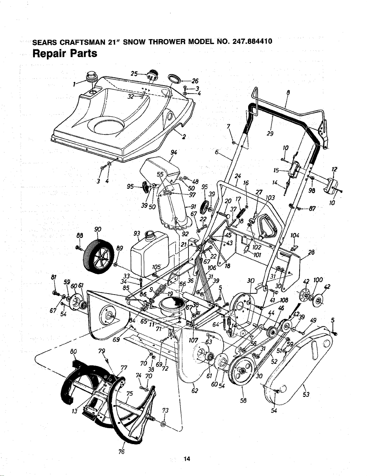
'_SEARS CRAFTSMAN 21" SNOW THROWER MODEL NO. 247.884410
Repair Parts
29
I0
88
9O
93
85
67
5_
70
70
?3
62
58
54
53
/
14
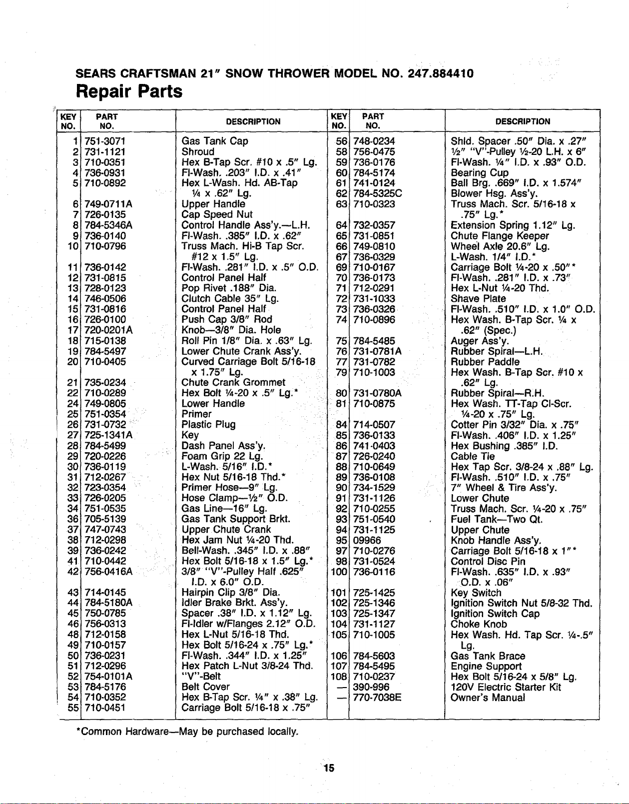
SEARS CRAFTSMAN 21" SNOW THROWER MODEL NO. 247.884410
Repair Parts
PART
NO,
751-3071
731-1121
710-0351
736-0931
710-0892
749-0711A
726-0135
784-5346A
736-0140
710-0796
736-0142
731-0815
728-0123
746-0506
731-0816
726-0100
720-0201A
715-0138
784-5497
7! 0-0405
735-0234
710-0289
749-0805
751-0354
731-0732 _'_
725-1341A
784-5499
720-0226
736-0119
712-0267
723-0354
726-0205
751-0535
705-5139
747-0743 :
712-0298
736-0242
710-0442
756-0416A
714-0t45
784-5180A
750-0785
756-0313
712-0158
710-0157
736-0231
712-0296
754-0101A
784-5176
710-0352
710-0451
KEY
DESCRIPTION NO.
Gas Tank Cap
Shroud
Hex B-Tap Scr. #10 x .5" Lg.
Fl-Wash..203" I.D. x .41"
Hex L-Wash. Hal. AB-Tap
1_ x .62" Lg.
Upper Handle
Cap Speed Nut
Control Handle Ass'y.--L.H.
FI-Wash..385" I.D. x .62"
Truss Mach. Hi-B Tap Scr,
#12 x 1.5" Lg.
FI-Wash..281" I.D. x .5" O.D.
Control Panel Half
Pop Rivet .188" Dia.
Clutch Cable 35" Lg.
Control Panel Half
Push Cap 3t8" Rod
Knob--3t8" Dia. Hole
Roll Pin 118" Dia. x ,63" Lg. 75
Lower Chute Crank Ass'y. 76
Curved Carriage Bolt 5116-18 77
x 1.75" Lg. 79
Chute Crank Grommet
Hex Bolt V4-20 x .5" Lg:* _ _ 80
Lower Handle _ 81
Primer _J
PART
NO.
56 748-0234
58 756-0475
59 736-0176
60 784-5174
61 741-0124
62 784-5325C
63 710.0323
64 732-0357
65 731-0851
66 749-0810
67 736-0329
69 710-0167
70 736-0173
71 712-0291
72 731-1033
73 736-0326
74 710-0896
784-5485
731-0781A
731-0782
710-1003
731-0780A
710-0875
Plastic Plug
Key
Dash Panel Ass'y.
Foam Grip 22 Lg.
L-Wash. 5116, I.D.*
Hex Nut 5116-18 Thd.*
Primer Hose--9" :Lg.
Hose Clamp--I/2" O.D.
Gas Line--16" Lg.
Gas Tank Support Brkt.
Upper Chute Crank
Hex Jam Nut 1/_-20Thd.
Bell-Wash..345" I.D. x ,88"
Hex Bolt 5116-18 x 1.5" Lg.*
3t8" "V"-Pulley Half .625"
I.D. x 6.0" O.D.
Hairpin Clip 3t8" Dia.
Idler Brake Brkt. Ass'y.
Spacer .38" I.D. x 1.12" Lg.
Fl-ldler w/Flanges 2.12" O.D.
Hex L-Nut 5/16-18 Thd.
Hex Bolt 5/16-24 x .75" Lg.*
FI-Wash..344" I.D. x 1.25"
Hex Patch L-Nut 3/8-24 Thd.
"V"-Belt
Belt Cover
Hex B-Tap Scr. 1/4" x .38" Lg.
Carriage Bolt 5!16-t8 x .75"
_84 714-0507
85 736-0133
86 741-0403
87 726-0240
88 710-0649
89 736-0108
90 734-1529
91'731-1126
92 710-0255
93 751-0540
94 731-1125
95 09966
97 710-0276
98 731-0524
100 736-0116
101 726-1425
102 725-1346
103 725-1347
104 731-1127
_105 710.1005
106 784-5603
107 784-5495
108 710-0237
390-996
-- 770-7038E
J DESCRIPTION ........................
Shld. Spacer .50" Dia. x .27"
1/2" "V"-Pulley 1/2-20L,H. x 6"
FI-Wash. 1/4" I.D. x .93" O.D.
Bearing Cup
Ball Brg..669" i.D. x 1.574"
Blower Hsg. Ass'y,
Truss Mach. Scr. 5/16-18 x
.75" Lg.*
Extension Spring 1.12" Lg.
Chute Flange Keeper
Wheel Axle 20.6" Lg.
L-Wash. 1/4" I,D.*
Carriage Bolt 1/4-20x .50" *
FI-Wash..281" I.D. x .73"
Hex L-Nut 1/4-20Thd.
I Shave Plate
FI-Wash..510" I.D. x 1.0" O.D.
Hex Wash. B-Tap Scr. 1/_x
.62" (Spec.)
Auger Ass'y.
Rubber SpiraI--L.H.
Rubber Paddle
Hex Wash. B-Tap Scr. #10 x
.62" Lg.
Rubber SpiraI--R.H.
Hex Wash. TT-Tap Cl-Scr.
1/4-20x .75" Lg:
Cotter Pin 3/32" Dia. x .75"
FI-Wash..406" IoD. x !.25"
Hex Bushing .385" I.D.
Cable Tie
Hex Tap Scr. 318-24 x .88" Lg.
FI-Wash..510" I.D. x .75"
• 7, Wheel & Tire Ass'y.
Lower Chute
Truss Mach. Scr. 1/4-20x .75"
Fuel Tank--Two Qt.
Upper Chute
Knob Handle Ass'y.
Carriage Bolt 5116-18 x 1"*
Control Disc Pin
FI-Wash..635" i.D. x .93"
O.D. x ,06"
Key Switch
Ignition Switch Nut 518-32 Thd.
Ignition Switch Cap
Choke Knob
Hex Wash. Hd. Tap Scr. 1/4-.5"
Lg.
Gas Tank Brace
Engine Support
Hex Bolt 5/16-24 x 5t8" Lg.
120V Electric Starter Kit
Owner's Manual
*Common Hardware--May be purchased locally.
15
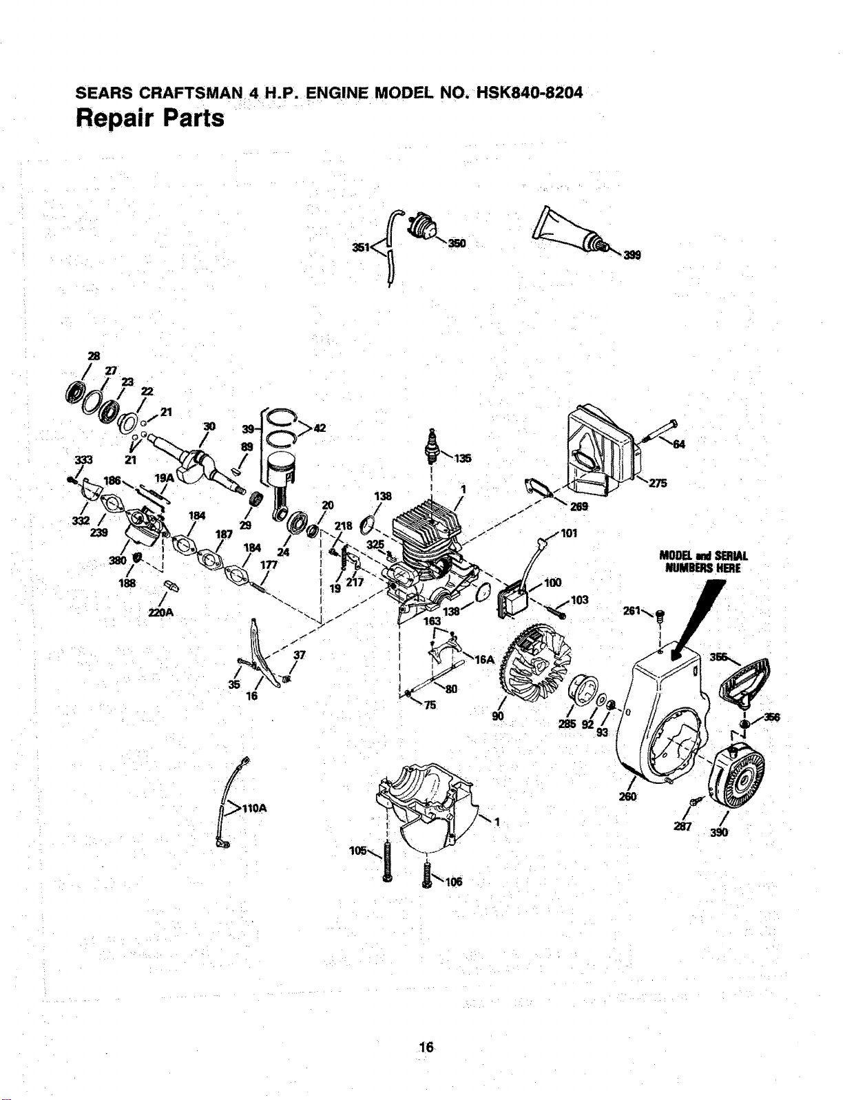
SEARS CRAFTSMAN 4 H.P. ENGINE MODEL NO. HSK840-8204
Repair Parts
35O
28
/
27 ¸
333 21
/
332
239 18
MODELandSERIAL
NUMBERSHERE
9O
/
285
F
287
/
390¸
16
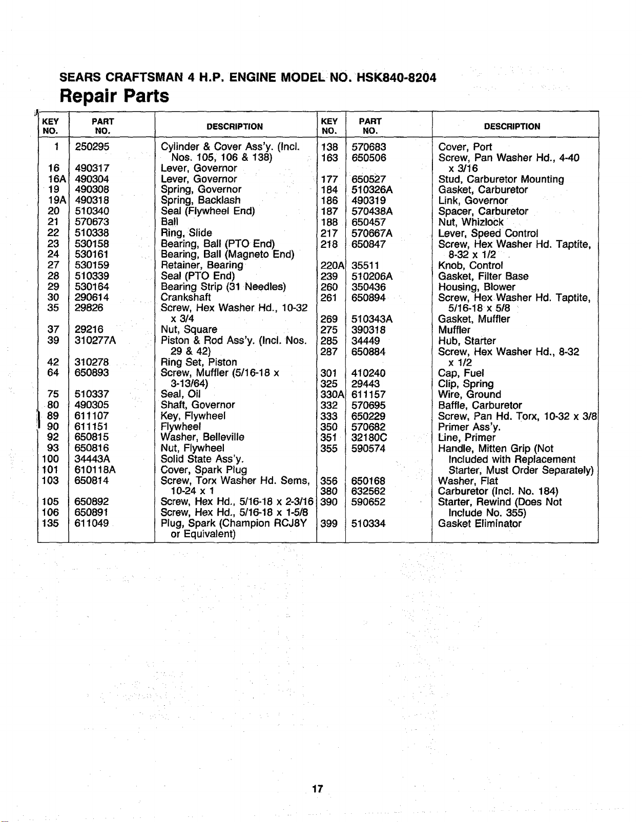
SEARS CRAFTSMAN 4 H.P. ENGINE MODEL NO. HSK840.8204
Repair Parts
KEY PART
NO. NO.
1 250295
16 490317
16AI 490304
19 490308
19AI 490318
20 510340
21 570673
22 510338
23 530158
24 530161
27 530159
28 510339
29 530164
30 290614
35 29826
DESCRIPTION
Cylinder & Cover Ass'y. (inc!.
Nos. 105, 106 & 138)
Lever, Governor
Lever, Governor
Spring, Governor
Spring, Backlash
Seat (Flywheel End)
Ball
Ring, Slide
Bearing, Ball (PTO End)
Bearing, Ball (Magneto End)
Retainer, Bearing
Seal (PTO End)
Bearing Strip (31 Needles)
Crankshaft
Screw, Hex Washer Hd., 10-32
x 3/4
Nut, Square
Piston & Rod Ass'y. (Incl. Nos.
29 & 42)
Ring Set, Piston
Screw, Muffler (5/16,18 x
3-13t64)
Seal, Oil
Shaft, Governor
Key, Flywheel
Flywheel
Washer, Bellevilte
Nut, Flywheel
Solid State Ass'y.
Cover, Spark Plug
Screw, Torx Washer Hd. Sems,
10-24 x 1
Screw, Hex Hd., 5/16-18 x 2-3116
Screw, Hex Hd., 5116-18 x 1-5/8
Plug, Spark (Champion RCJ8Y
or Equivalent)
37 29216
39 310277A
42 310278
64 650893
75
80
89
90
92
93
100
101
103
510337
490305
611107
611151
650815
650816
34443A
610118A
650814
105 650892
106 650891
135 611049
KEY
NO.
138
163
_i177
184
186
187
188
217
218
220A
239
260
261
269
275
285
287
301
325
330,_
332
333
35O
351
355
356
380
1390
1399
PART
NO.
570683
650506
650527
510326A
490319
570438A
650457
570667A
650847
35511
5!0206A
350436
650894
510343A
390318
34449
650884
DESCRIPTION
Cover, Port
Screw, Pan Washer Hd., 4-40
x 3116
Stud, Carburetor Mounting
Gasket, Carburetor
Link, Governor
Spacer, Carburetor
Nut, Whizlock
Lever, Speed Control
Screw, Hex Washer Hd. Taptite,
8-32 x 1/2
Knob, Control
Gasket, Filter Base
Housing, Blower
Screw, Hex Washer Hd. Taptite,
5/16-18 x 5/8
Gasket, Muffler
410240
29443
611157
570695
650229
570682
32180C
590574
650168
632562
590652
510334
Muffler
Hub, Starter
Screw, Hex Washer Hd., 8-32
x 1/2
Cap, Fuel
Clip, Spring
Wire, Ground
Baffle, Carburetor
Screw, Pan Hd. Torx, 10-32 x 318
Primer Ass'y.
Line, Primer
Handle, Mitten Grip (Not
Included with Replacement
Starter, Must Order Separately)
Washer, Flat
Carburetor (Incl. No. 184)
Starter, Rewind (Does Not
Include No. 355)
Gasket Eliminator
17
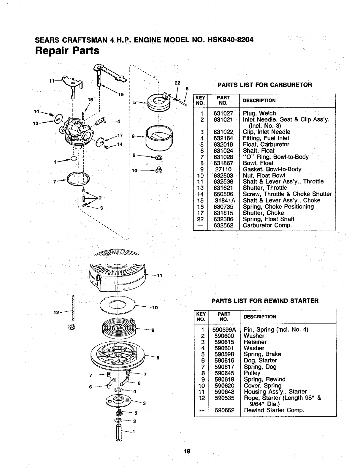
SEARS CRAFTSMAN 4 H.P. ENGINE MODEL NO. HSK840-8204
Repair Parts
i ¸ ,
I I
i .>2
22
_ 6
_'_'1_/ KEY PART
NO, NO.
1 631027
2 631021
PARTS LIST FOR CARBURETOR
3 631022
4 632164
5 632019
6 631024
7 631028
8 631867
9 27110
10 632503
11 632538
13 631621
14 650506
t5 3184tA
16 630735
17 631815
22 632386
632562
DESCRIPTION
Plug, Welch
Inlet Needle, Seat & Clip Ass'y.
(incl. No. 3)
Clip, Inlet Needle
Fitting, Fuel Inlet
Float, Carburetor
Shaft, Float
"O" Ring, Bowl-to-Body
Bowl, Float
Gasket, Bowl-to-Body
Nut, Float Bowl
Shaft & Lever Ass'y. Throttle
Shutter, Throttle
Screw, Throttle & Choke Shutter
Shaft & Lever Ass'y., Choke
Spring, Choke Positioning
Shutter, Choke
Spring, Float Shaft
Carburetor Comp.
11
i
PARTS LIST FOR REWIND STARTER
KEY PART
NO. NO, DESCRIPTION
1 590599A
2 590600
3 590615
4 590601
5 590598
6 590616
7 590617
8 590645
9 5906t9
10 590620
11 590643
12 590535
590652
Pin, Spring (Incl. No. 4)
Washer
Retainer
Washer
Spring, Brake
Dog, Starter
Spring, Dog
Pulley
Spring, Rewind
Cover, Spring
Housing Ass'y., Starter
Rope, Starter (Length 98" &
9164" Dia.)
Rewind Starter Comp.
18
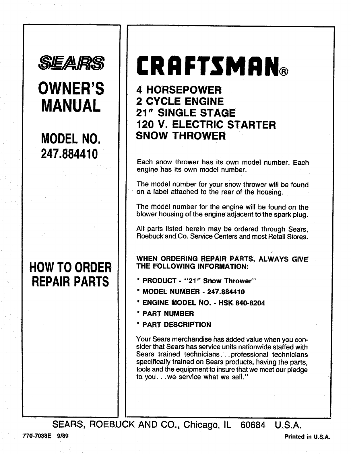
OWNER'S
MANUAL
MODELNO.
247.884410
HOWTOORDER
REPAIRPARTS
CRRFTSMRN®
4 HORSEPOWER
2 CYCLE ENGINE
21" SINGLE STAGE
1120V. ELECTRIC STARTER
SNOW THROWER
Each .snow thrower ihas its own model number. Each
engine has its own model number.
The model number for your snow thrower will be found
on a label attached to the rear of the housing,
The model number for the engine will be found on the
blower'housing of the engine adjacent to,the spark plug.
All parts listed herein may be ordered through Sears,
Roebuck and Co. ServiceCenters and mostRetail Stores.
/
WHEN ORDERING REPAIR PARTS, ALWAYS GIVE
THE FOLLOWING INFORMATION:
* PRODUCT - "21" Snow Thrower"
* MODEL NUMBER - 247.884410
* ENGINE MODEL NO. - HSK 840-8204
* PART NUMBER
* PART DESCRIPTION
Your Sears merchandise has added value •whenyou con-
siderthat Sears has service units nationwidestaffed with
Sears trained technicians...professional technicians
specifically trained on Sears products,,having the parts,
toolsand the equipment to insurethatwe meet our pledge
to you.,, we service what we sell."
'lllh ...... 1ill= ,,....
SEARS, ROEBUCK AND CO., Chicago, IL
770,7038E 9/89
60684 U.S.A.
Printed in U.S_A,


