Questions, problems or missing parts? Before returning this item to your retailer, call our customer service department
at 1-877-706-3267, Monday - Thursday, 8am - 6pm, Friday, 8am - 5pm EST.
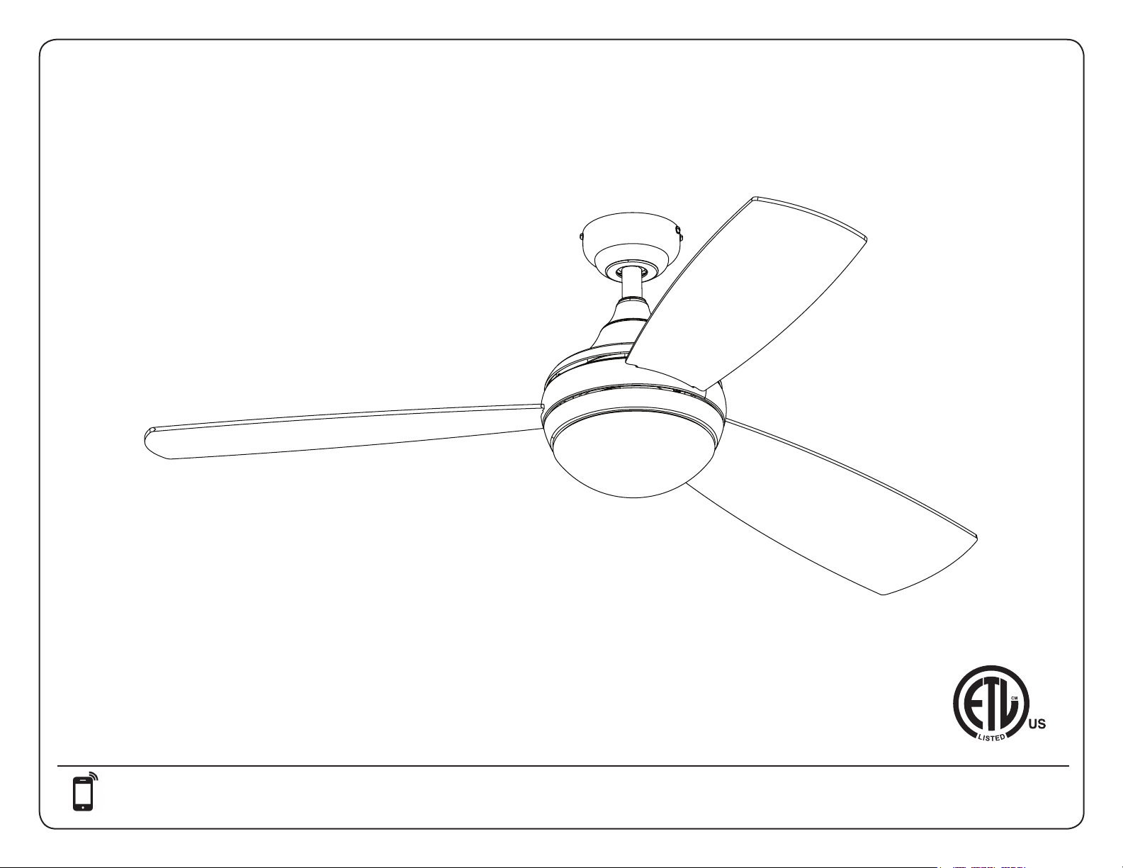
Models #080034, 080035, 080036
52 INCH CEILING FAN
2
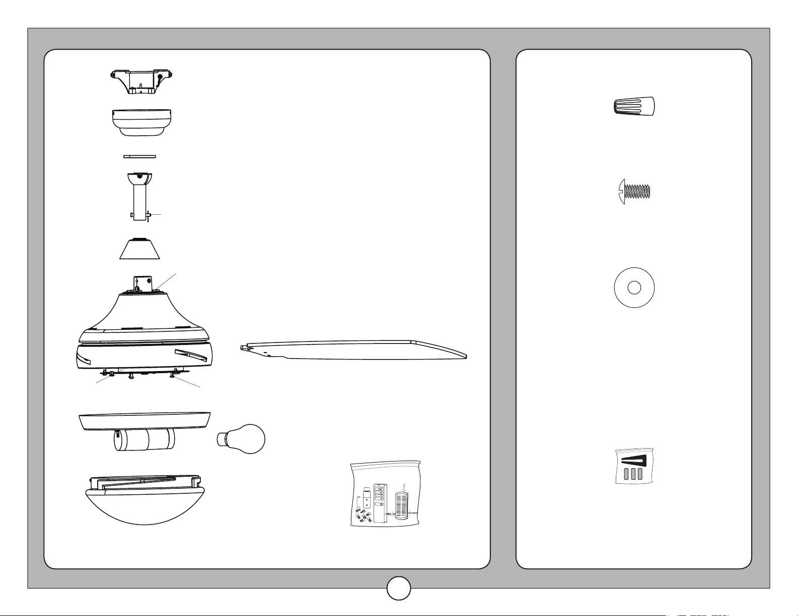
PACKAGE CONTENTS HARDWARE CONTENTS
(not drawn to scale)
Note: Some extra fasteners are included for your
convenience.
Blade Balancing Kit
Blade Washer (x 9)
Blade Screw (x 9)
Wire Connector (x 6)
Fitter Plate
Screw (x 3)
Bulb (x 2)
Mounting Bracket
Canopy
Canopy Cover
Downrod
ClipPin
Blade (x 3)
Yoke Cover
Yoke
Closemount
Screw (x 3)
Motor Assembly
Fitter Plate
Light Kit
Glass Bowl
Remote Pack
3
TABLE OF CONTENTS
PREPARATION
Before beginning the assembly of this product, ensure all parts are present. Compare all parts with the package contents list and hardware contents
list. If any part is missing or damaged, do not attempt to assemble the product.
Estimated Assembly Time: 120 minutes
Tools required for assembly (not included): Electrical tape, Phillips Screwdriver, Pliers, Safety Glasses, Step Ladder, and Wire Strippers
Helpful Tools (not included): AC Tester Light, Tape Measure, Wiring Handbook and Wire Cutters
Package Contents .....................................................................................................2
Preparation ..........................................................................................................3
Initial Installation ......................................................................................................5
Downrod or Angle Mounting .............................................................................................6
Closemount Instructions ................................................................................................8
Final Installation. . . . . . . . . . . . . . . . . . . . . . . . . . . . . . . . . . . . . . . . . . . . . . . . . . . . . . . . . . . . . . . . . . . . . . . . . . . . . . . . . . . . . . . . . . . . . . . . . . . . . . . 9
Operating Instructions .................................................................................................12
Safety Information ....................................................................................................13
Care and Maintenance ................................................................................................13
Troubleshooting ......................................................................................................14
Warranty ...........................................................................................................15
4
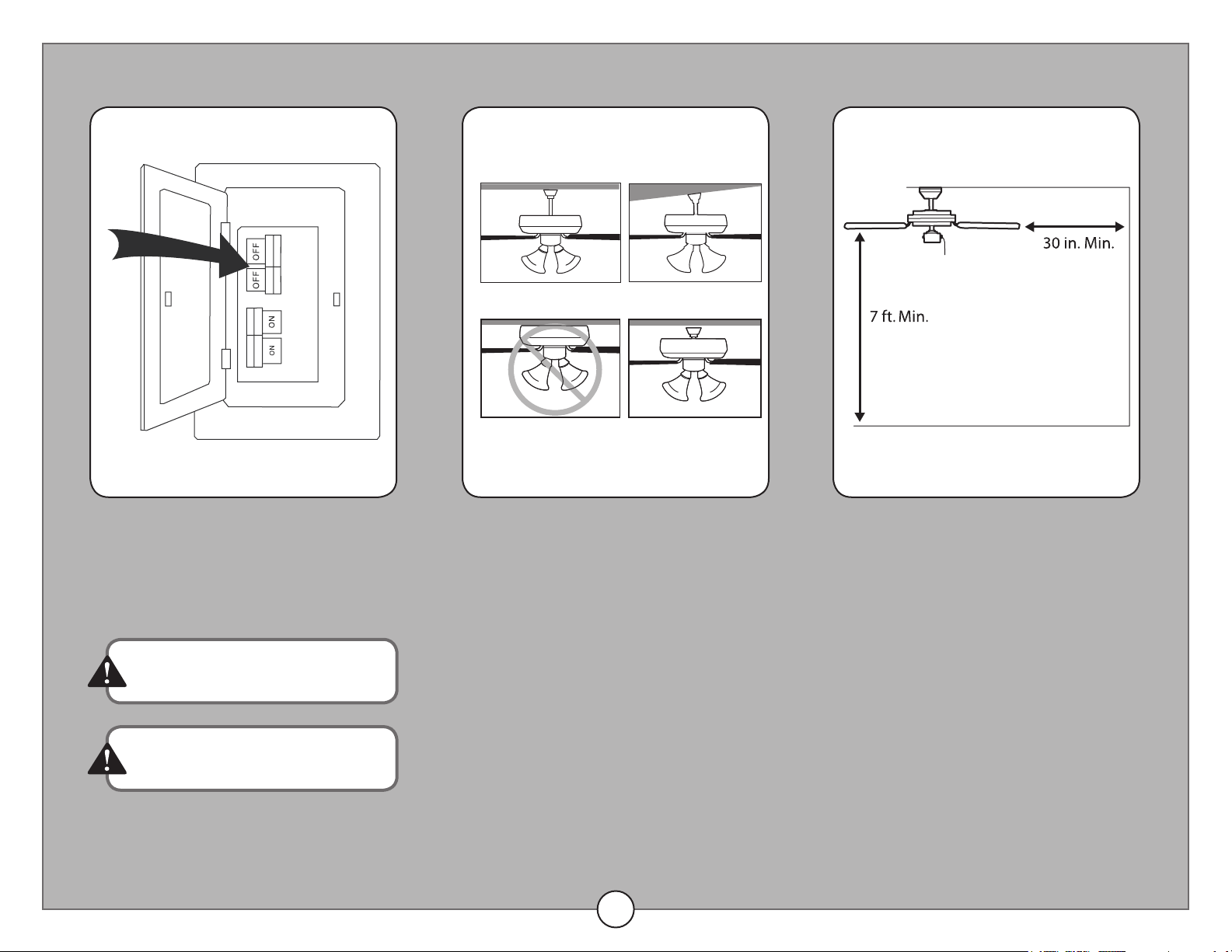
PREPARATION
1. Turn o power.
Turn o the power to the fan at the breaker
box and the wall switch.
2. Choose mounting option.
Standard Mounting is best suited for
ceilings 8 ft. or higher. For very high ceilings,
use a longer downrod (not included).
Angle Mounting is best suited for angled
or vaulted ceilings. A longer downrod is
sometimes necessary to ensure proper
blade clearance. Ensure the ceiling angle is
not steeper than 10 degrees.
Flushmount installation is not available for
this item.
Closemount installation is best suited for
ceilings 8 ft. or lower.
3. Choose suitable location.
Ensure the blades will be at least 30 inch-
es from any obstructions. Also check the
downrod length to ensure the blades will be
at least 7 feet above the oor.
Failure to disconnect the power supply
prior to installation may result in serious
injury or death.
See page 13 for complete description of
cautions and warnings.
Downrod Mounting
Flushmount Closemount
Angle Mounting
5
INITIAL INSTALLATION
Standard and
Closemount
Mounting
Angle
Mounting
D
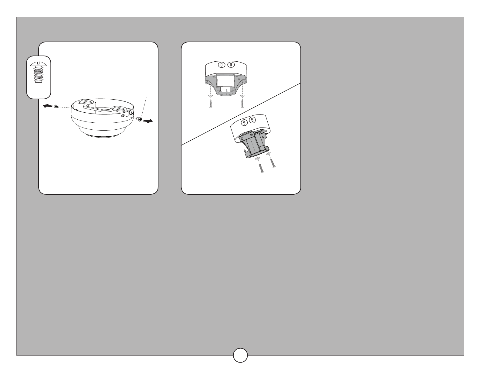
2. Install the mounting bracket.
Install the mounting bracket to the outlet
box (sold separately) using the screws and
washers provided with the outlet box.
For Closemount Installation, skip to Page 8.
1. Remove the mounting bracket.
Loosen all four mounting bracket screws
and completely remove the two screws from
the round holes in the canopy. Then, remove
the mounting bracket from the canopy.
Note: Save the mounting bracket screws for
later use.
x 4
Mounting
Bracket
Screw
6
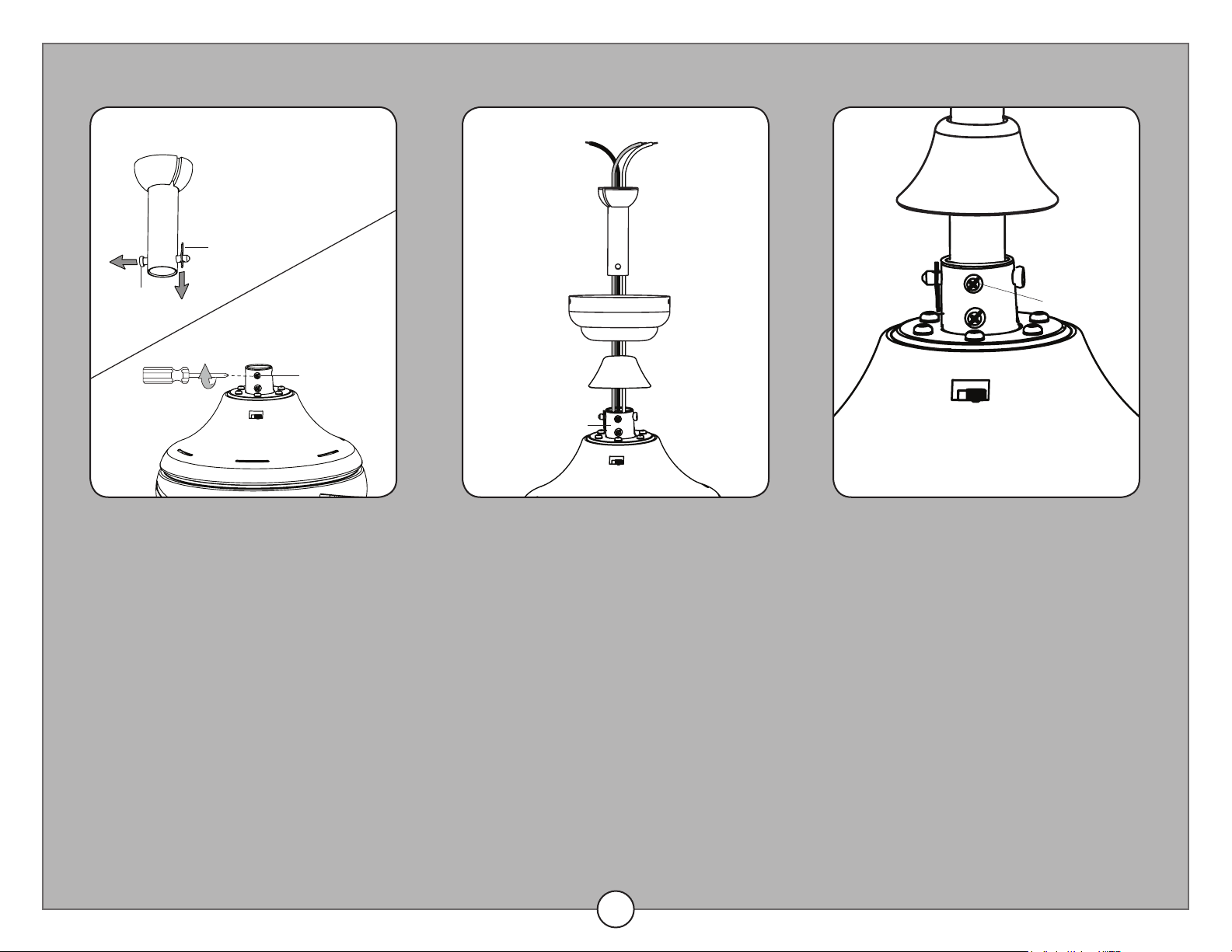
1. Loosen set screws and remove
pin and clip.
Remove the clip and pin from the downrod.
Then partially loosen the two set screws in
the yoke at the top of the motor assembly.
2. Feed the wires through the yoke
cover, canopy, and downrod.
3. Install the downrod into the
yoke.
Slide the downrod into the yoke at the top
of the motor assembly. Align the holes, and
reinstall the pin and clip. Then securely
tighten both set screws.
DOWNROD OR ANGLE MOUNTING
Clip
Clip
Pin
Pin
Set Screw
Set Screw
Downrod
Downrod
Canopy
Yoke Cover
Yoke
7
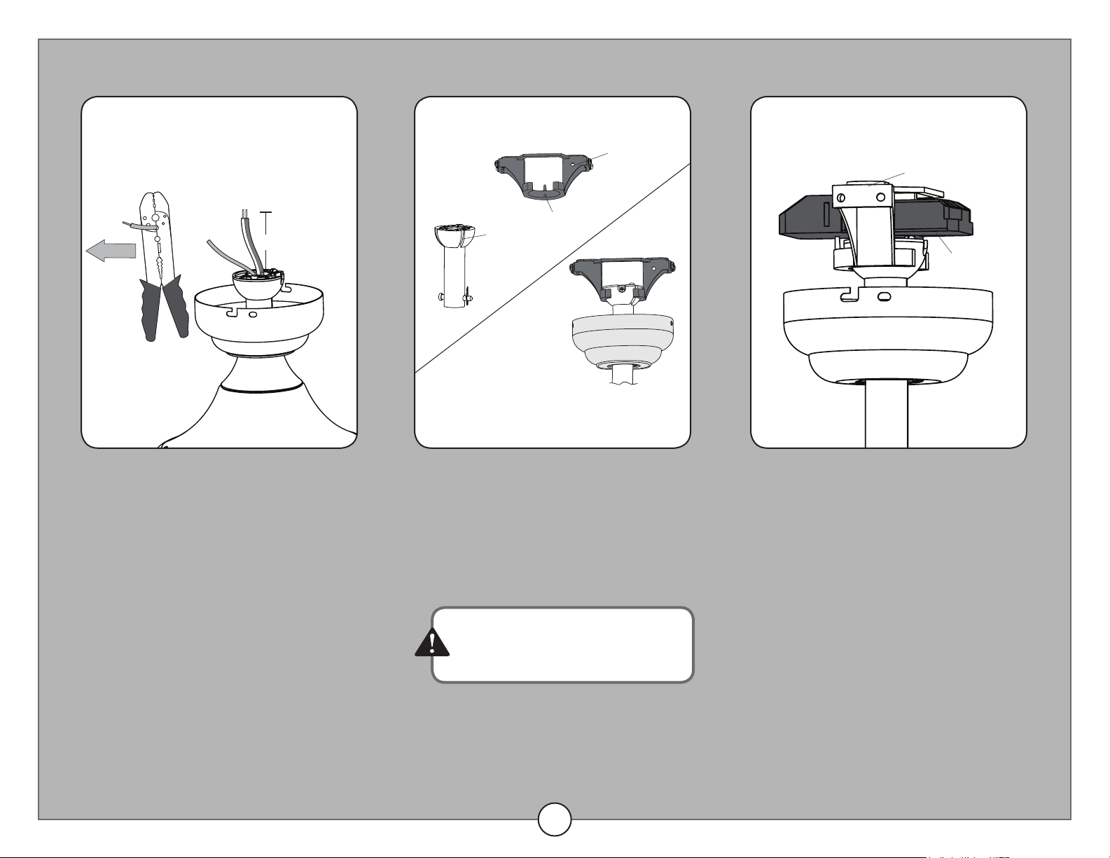
4. Trim fan wires.
Depending on the length of downrod you
use, you may want to cut the fan wires to
simplify wiring. After pulling the wires all the
way through the downrod, measure 8 inches
of wire. Cut o the excess wire using wire
cutters (not included).
Strip 1/2 inch of insulation from the end of
each wire. Twist the stripped ends of each
wire strand. Note: If you didn’t trim the wires
in the previous step, this step is not neces-
sary.
6. Place receiver in mounting
bracket.
5. Hang downrod in mounting
bracket.
Install the ball end of the downrod into the
opening of the mounting bracket. Align the
slot in the ball with the tab on the mounting
bracket.
Proceed to FINAL INSTALLATION, page 9.
DOWNROD OR ANGLE MOUNTING
Failure to align the slot in the ball with the
tab on the mounting bracket may cause
the fan to fall, which could result in injury
or death.
8 in.
Mounting Bracket
Mounting Bracket
Receiver
Downrod
Slot
Tab
8
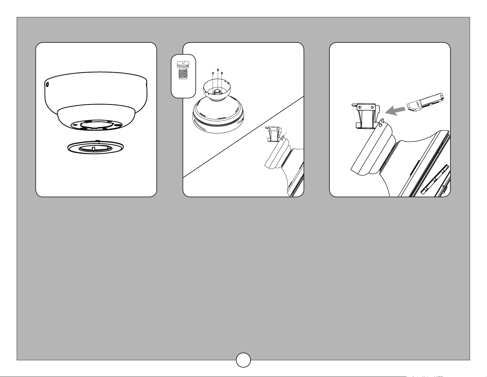
1. Remove canopy cover from
bottom of canopy.
The canopy cover snaps out of the hole in
the bottom of the canopy.
2. Install canopy to top of motor
assembly.
Remove the three Phillips-head closemount
screws from the top of the motor assembly.
Then, align the canopy with the holes in the
top of the motor assembly. The larger holes
in the canopy will encompass the remaining
screws. Secure the canopy to the top of
the motor assembly with the closemount
screws.
Then, raise the motor assembly and place
the canopy on the mounting bracket hook
to temporarily hold the fan during the wiring
process.
3. Insert the receiver into the
mounting bracket.
Insert the receiver into the opening of the
mounting bracket to prepare for the wiring
process.
Note: The receiver rests in the opening of
the mounting bracket. It will be held in place
when the canopy is secured to the mounting
bracket.
CLOSEMOUNT INSTALLATION (optional)
x 3
Canopy Cover
Canopy
Closemount Screw
Mounting Bracket
Hook
Canopy
Receiver
9
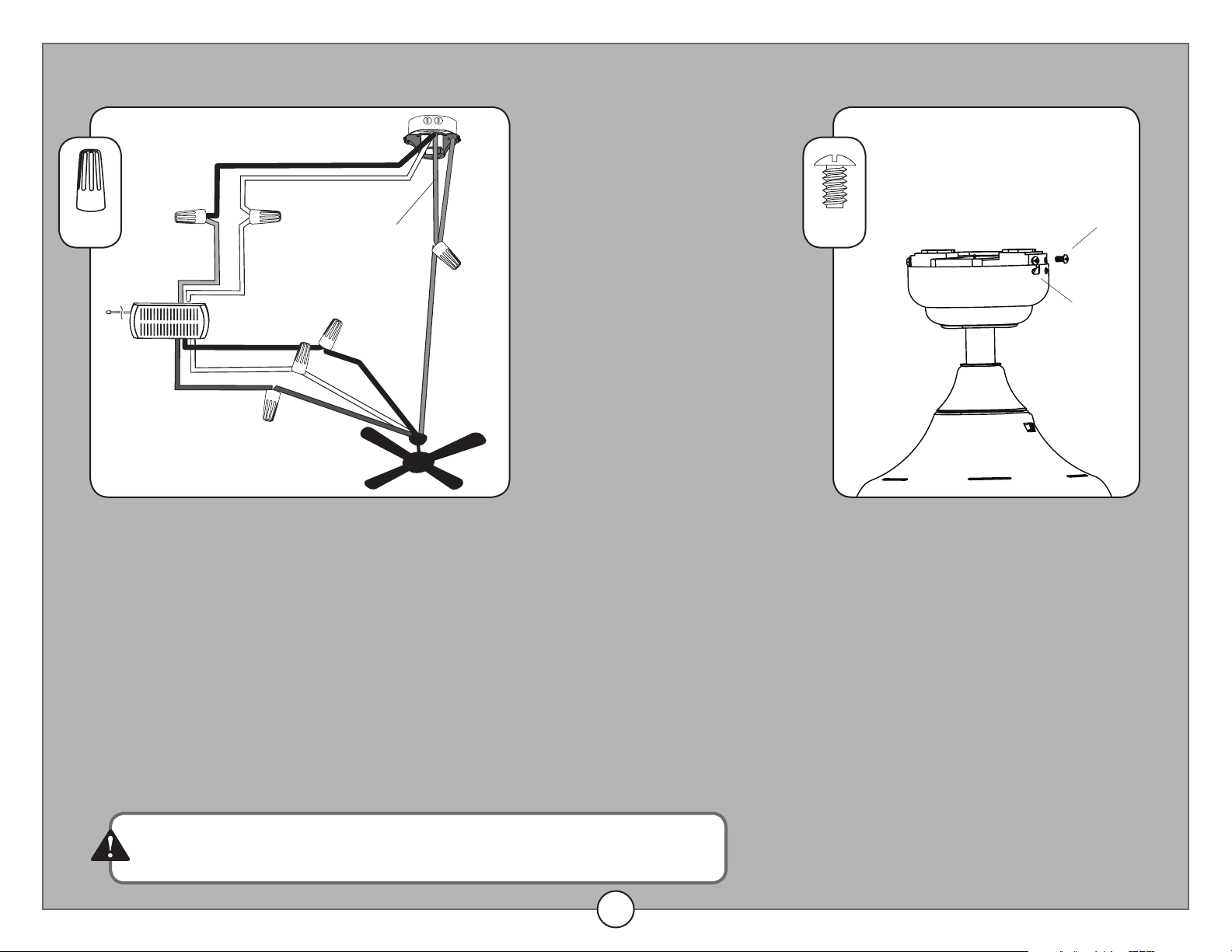
Black (hot/power)
White (neutral)
Bare/Green
(ground)
Red
White
White
White
Black
Blue
Blue
Black
Green
Green
Receiver
1. Wire the fan.
Connect household supply and fan wires according to the diagram and these steps:
• Connect the white wire with the red label from the receiver to the white (neutral/common)
supply wire.
• Connect the red wire with the red label from the receiver to the black (hot/power) supply wire.
• Connect the green wire from the fan and the mounting bracket to the bare/green (ground)
supply wire.
• Connect the black wire from the receiver to the black fan wire.
• Connect the white wire from the receiver to the white fan wire.
• Connect the blue wire from the receiver to the blue fan wire.
Important: After the connections have been made, the wires should be turned upward and
pushed carefully up into the outlet box. Place the black and white wire connections on opposite
sides of the outlet box.
2. Attach the canopy to the
mounting bracket.
Align the canopy over the loosened
mounting bracket scews preassembled to
the mounting bracket. Place the J-slot of the
canopy onto the mounting bracket screws
and rotate clockwise.
Re-install the two previously removed
mounting bracket screws into the round
holes of the canopy and tighten all four
mounting bracket screws.
FINAL INSTALLATION
x 6 x 4
Mounting
Bracket
Screw
If the household supply wires are dierent colors than those referred to
above, a professional electrician should determine proper wiring.
Canopy
J-slot
10
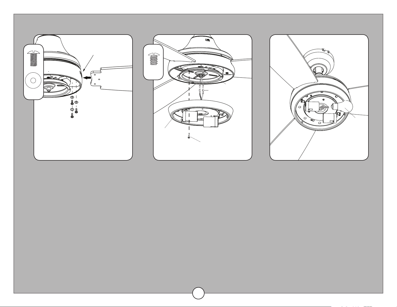
3. Attach blades to motor.
Insert blade through slot in the side of
the motor assembly. Align the holes of
one blade with three blade screw holes in
underside of the motor assembly. Secure
with three blade screws and blade washers.
Repeat this step for the remaining blades.
4. Connect light kit wires.
Remove one of the three tter plate screws
preassembled to the tter plate and loosen
the other two but do not remove.
Connect the single-pin connector from the
tter plate to the single-pin connector from
the light kit -- blue to black and white to
white. Align the slotted holes in the light
kit with the loosened screws in the tter
plate. Turn light kit clockwise and replace
the previously removed tter plate screw.
Tighten all screws.
FINAL INSTALLATION
x 9
x 3
Slot
Blade Screw
Blade Washer
Fitter Plate
Screw
Light Kit
Single-pin
Connector
Fitter Plate
5. Install the two E26-base LED
bulbs.
Replacement Bulbs - Use E26-base LED,
CFL, or incandescent bulbs (60 watts max.).
Halogen bulbs are not recommended for this
item.
Bulb
11
FINAL INSTALLATION
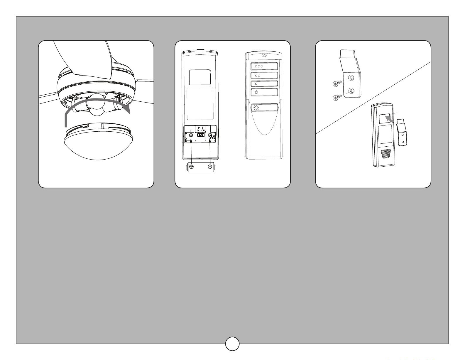
7. Install battery.
Remove the battery cover from the back of
the remote found in remote pack. Insert the
battery from remote pack into the remote;
ensure polarity of battery matches the po-
larity indicated in the battery compartment --
positive (+) to positive (+) and negative (-) to
negative (-). Replace the battery cover and
press the fan power button on the remote to
ensure the LED indicator illuminates and the
remote turns on the fan.
Note: If remote doesn’t turn on the fan, see
TROUBLESHOOTING.
6. Install glass bowl.
Lift the glass bowl into the light kit and twist
in a clockwise direction until it is secure.
8. Install wall bracket.
If you wish to install the wall bracket from
the remote pack, choose desired location
and insert screws from remote pack into
holes of wall bracket and into installation
site. Store the remote on the wall bracket by
placing the slot on the back of the remote
onto the wall bracket.
Battery
Wall Bracket
Slot
12
1
2
3
4
5
6
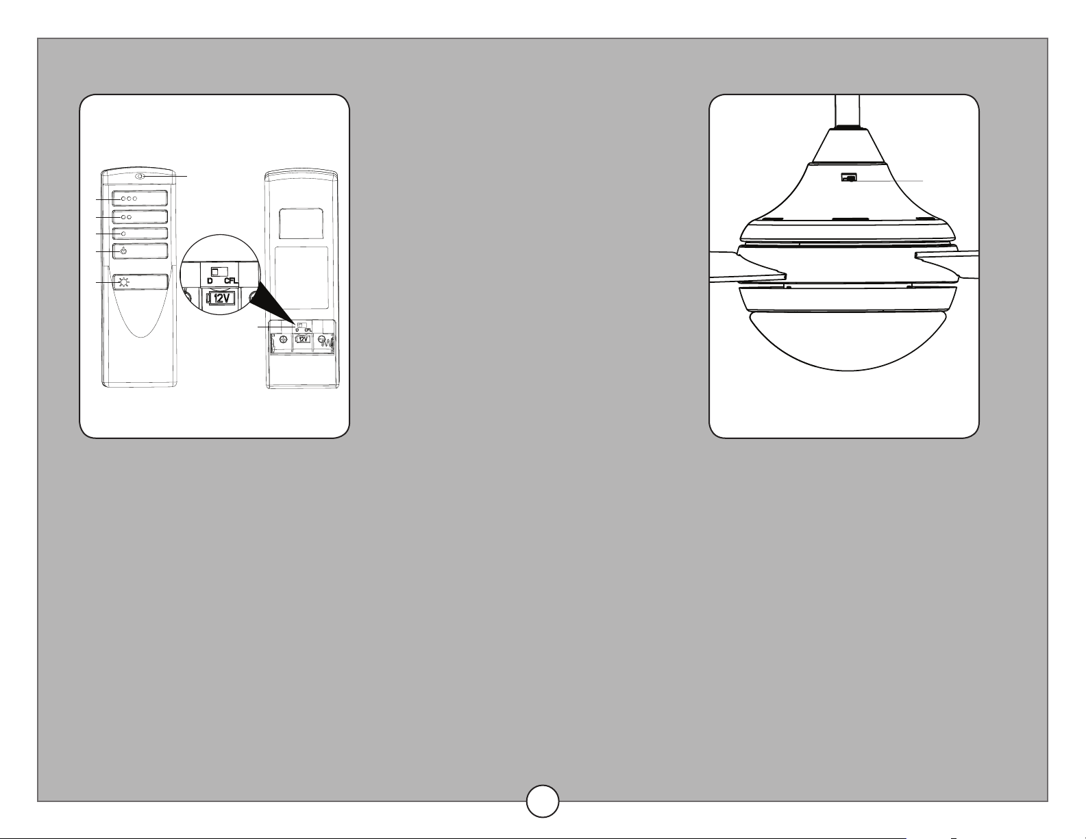
1. Remote operation.
To operate the fan using the remote, press and release the following buttons:
1 - High fan speed
2 - Medium fan speed
3 - Low fan speed
4 - Fan Power - Turns the fan o.
Light Delay O mode - Press and hold the fan power button (4) for ve seconds,
which will turn o light after one minute. The LED indicator on the remote will ash four
times to conrm mode setting.
5 - Light Control:
Dimmable Bulbs - Press light control to turn lights o and on. Press and hold light
control to dim or brighten the lights.
Nondimmable Bulbs -Turns the lights on and o. Note: The dimmer function does
not work with nondimmable bulbs.
6 - D/CFL Switch: Switch should be set to “D” to correspond with the included
dimmable bulbs. Flip to “CFL” if you change to non-dimmable bulbs.
2. Reverse switch operation.
Use the fan reverse switch, located on the
switch housing to optimize your fan for
seasonal performance.
Using a ceiling fan will allow you to raise
your thermostat setting in summer and lower
your thermostat setting in winter without
feeling a dierence in your comfort.
Note: Wait for the fan to stop before moving
the reverse switch.
In warmer weather, push the reverse
switch left which will result in downward
airow creating a wind chill eect.
In cooler weather, push the reverse switch
right which will result in upward airow that
can help move stagnant, hot air o the
ceiling area.
OPERATING INSTRUCTIONS
LED Indicator
Reverse
Switch

13
SAFETY INFORMATION
CARE AND MAINTENANCE
Please read and understand this entire manual before attempting to assemble, operate or install the product.
• Before you begin installing the fan, disconnect the power by removing fuses or turning o the circuit breakers.
• Make sure all electrical connections comply with local codes, ordinances, the National Electrical Code and ANSI/NFPA 70-199. Hire a qualied electrician or consult a
do-it-yourself wiring handbook if you are unfamiliar with installing electrical wiring.
• Make sure the installation site you choose allows a minimum clearance of 7 ft. from the blades to the oor and at least 30 in. from the end of the blades to any
obstruction.
• The net weight of this fan is: 15.14 lbs.
DANGER: When using an existing outlet box, make sure the outlet box is securely attached to the building structure and can support the full weight of the fan.
Failure to do this can result in serious injury or death. The stability of the outlet box is essential in minimizing wobble and noise in the fan after installation is complete.
WARNING: To avoid personal injury, the use of gloves may be necessary while handling fan parts with sharp edges.
WARNING: Using a full-range dimmer switch to control fan speed will cause a loud humming noise from the fan. To reduce the risk of re or electric shock, do NOT
use a full-range dimmer switch to control the fan speed.
WARNING: To reduce the risk of re, electric shock or personal injury, mount the fan to an outlet box marked “ACCEPTABLE FOR FAN SUPPORT” and use the
mounting screws provided with the outlet box. Most outlet boxes commonly used for the support of lighting xtures are not acceptable for fan support and may need to
be replaced. Consult a qualied electrician if in doubt. Secure the outlet box directly to the building structure. The outlet box and its support must be able to support the
moving weight of the fan (at least 35 lbs.).
WARNING: To reduce the risk of re, electric shock or personal injury, wire connectors provided with this fan are designed to accept only one 12-gauge house wire
and two lead wires from the fan. If your house wire is larger than 12-gauge and/or there is more than one house wire to connect to the two fan lead wires, consult an
electrician for the proper size wire connectors to use.
WARNING: To reduce the risk of re, electric shock or personal injury, do not bend the blade arms when installing them, balancing the blades or cleaning the fan.
Do not insert objects between the rotating fan blades.
WARNING: To reduce the risk of personal injury, use only parts provided with this fan. The use of parts OTHER than those provided with this fan will void the warranty.
CAUTION: Be sure the outlet box is properly grounded or a ground (green or bare) wire is present.
CAUTION: Carefully check all screws, bolts, and nuts on the fan assembly ensure they are secured.
At least twice each year, lower the canopy to check the downrod assembly and tighten all screws on the fan. Clean the motor housing with only a soft brush or lint-free cloth
to avoid scratching the nish. Clean the blades with a lint-free cloth.
Important: Shut o the main power supply before you begin any maintenance task. Do NOT use water or a damp cloth to clean the fan.
14
TROUBLESHOOTING
The fan does not move.
The fan is noisy.
The fan wobbles
excessively.
The fan operates correctly
but the lights are not
working.
Remote control does not
work.
1. Firmly push the reverse switch completely left or right.
2. Make sure the wall switch is turned on.
3. Ensure power is on at wall switch and breaker box
4. Turn the power o and check all wire connections at the ceiling outlet box.
1. Check and tighten all screws that hold the fan blades to the blade arms and motor.
2. Replace any blade that is cracked or damaged.
3. Do not use a variable-speed wall control to control the fan speed.
4. Ensure the outlet box is securely mounted to the building structure.
5. Ensure the mounting bracket is securely mounted to the outlet box.
1. Tighten all screws that hold the fan blades to the blade arms and blade arms to motor.
2. Switch one blade with a blade from the opposite side. Or balance the fan using the blade balancing kit.
3. Turn o power. Loosen the canopy and verify that the mounting bracket is secure to the electrical outlet box. The
mounting bracket must be ush without movement against the outlet box.
4. Use a longer downrod or move the fan to another location if the fan is too close to the ceiling.
5. Ensure the mounting bracket is securely mounted to the outlet box.
6. Tighten the set screws in the yoke.
1. Install new bulbs.
2. Ensure the single-pin connectors from the switch housing to the light kit are connected properly.
3. Turn the power o and check all wire connections between the fan and outlet box.
1. Turn o the main power, then turn it back on. Within 30 seconds, press and hold the high and low speed buttons
on the remote at the same time for 5 seconds. The LED indicator will ash 3 times, signaling a successful
synchronization. Once complete, the fan will start on the low speed with the light (if applicable) o.
2. Insert new 12V battery in battery compartment of the remote control (see page 11).
3. If there are several fans in close proximity, turn power o to other fans and resync the remote to the receiver (see
corrective action 1 above).
PROBLEM CORRECTIVE ACTION
15
LIFETIME LIMITED WARRANTY
The manufacturer warrants this fan to be free from defects in workmanship and materials present at time of shipment from the factory for a lifetime
from the date of purchase by the original purchaser. The retailer also warrants that all other fan parts, excluding any glass or acrylic blades, to be
free from defects in workmanship and material at the time of shipment from the factory for a period of one year after the date of purchase by the
original purchaser. The manufacturer agrees to correct such defects without charge or at its option replace the ceiling fan with a comparable or
superior model.
To obtain warranty service, present a copy of the receipt as proof of purchase. All costs of removing and reinstalling the product are your
responsibility. Any damage to any part such as by accident or misuse or improper installation or by axing any accessories, is not covered by this
warranty. The manufacturer assumes no responsibility whatsoever for fan installation during the limited lifetime warranty. Any service performed by
an unauthorized person will render the warranty invalid.
Due to varying climate conditions, this warranty does not cover any changes in brass nish, including rusting, pitting, corroding, tarnishing or peeling.
Brass nishes of this type give their longest useful life when protected from varying weather conditions. Any glass provided with this fan is not
covered by the warranty.
Any replacement of defective parts from the ceiling fan must be reported within the rst year from the date of purchase. For the balance of the
warranty, call our customer service department for return authorization and shipping instructions so that we may repair or replace the ceiling fan.
Any fan or parts returned improperly is the sole responsibility of the purchaser. There is no other expressed warranty. The manufacturer disclaims
any and all warranties. The duration of any implied warranty which cannot be disclaimed is limited to the time period as specied in the expressed
warranty. The manufacturer shall not be liable for incidental, consequential, or special damages arising out of or in connection with product use or
performance except as may otherwise be accorded by law. This warranty gives specic legal rights, and you may also have other rights which vary
from state to state.
This warranty supersedes all prior warranties.
Note: A small amount of “wobble” is normal and should not be considered a defect.
9243 • 061317