www.klarstein.com
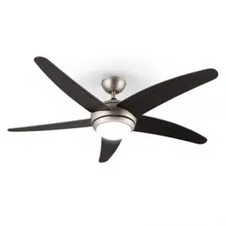
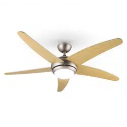
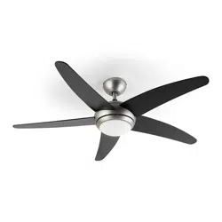
BOLERO
Deckenventilator
Ceiling Fan
Ventilateur de plafond
Ventilador de techo
Ventilatore a sotto
www.klarstein.com
10048081 10048082 10048083 10048084


3
DE
TECHNISCHE DATEN
Artikelnummer 10048081, 10048082, 10048083, 10048084
Stromversorgung 220-240 V~ 50/60 Hz
Ventilatorleistung 40 W
Maximaler Luftstrom 171 m
3
/min
Lampentyp E27 Lampenhalter, Max: 60 W
Technische Daten 3
Sicherheitshinweise 4
Lieferumfang 5
Installation 6
Inbetriebnahme 12
Spezielle Entsorgungshinweise für Verbraucher in Deutschland 14
Hinweise zur Entsorgung 16
Hersteller 16
Sehr geehrte Kundin, sehr geehrter Kunde,
wir gratulieren Ihnen zum Erwerb Ihres Gerätes.
Lesen Sie die folgenden Hinweise sorgfältig durch und
befolgen Sie diese, um möglichen Schäden vorzubeugen.
Für Schäden, die durch Missachtung der Hinweise und
unsachgemäßen Gebrauch entstehen, übernehmen wir
keine Haftung. Scannen Sie den QR-Code, um Zugriff
auf die aktuellste Bedienungsanleitung und weitere
Informationen rund um das Produkt zu erhalten.
INHALT

4
DE
SICHERHEITSHINWEISE
• Befestigen Sie den Ventilator niemals an einer Steckdose, sondern direkt an
der Decke.
• Der Mindestabstand zwischen den Flügeln des Ventilators und dem Boden
muss mehr als 2,3 m betragen. Die Tragfähigkeit des Hakens, an dem der
Ventilator aufgehängt wird, muss mindestens 100 kg betragen.
• Achten Sie darauf, dass Sie in der Zuleitung zum Deckenventilator einen
allpoligen Trennschalter mit einem Kontaktabstand von mindestens 3 mm
zwischen den Polen installieren.
• Das Modell oder die Typenbezeichnung von Leuchtmitteln, die in Ventilatoren
eingebaut werden können, die für diesen Zweck vorgesehen sind.
• Schalten Sie das Gerät vor dem Anschließen aus.
• Die elektrische Verkabelung muss den örtlichen Vorschriften entsprechen.
• Der Ventilator muss ordnungsgemäß geerdet sein, um das Risiko eines
Stromschlags zu vermeiden.
• Montieren Sie den Ventilator niemals in einem feuchten oder nassen Raum.
• Seien Sie vorsichtig, wenn Sie in der Nähe der rotierenden Flügel arbeiten.
• Dieses Gerät kann von Kindern ab 8 Jahren sowie von Personen mit
verringerten körperlichen, sensorischen oder mentalen Fähigkeiten oder
Mangel an Erfahrung und Wissen benutzt werden, wenn sie beaufsichtigt
oder bezüglich des sicheren Gebrauchs des Geräts angeleitet wurden und die
damit verbundenen Gefahren verstehen.
• Kinder dürfen nicht mit dem Gerät spielen.
• Die Reinigung und Wartung darf von Kindern nicht unbeaufsichtigt
durchgeführt werden.
• Vergewissern Sie sich, dass der Ventilator vom Stromnetz getrennt ist, bevor
Sie die Schutzvorrichtung entfernen.
• Treffen Sie Vorsichtsmaßnahmen, um zu verhindern, dass Gase aus dem
offenen Abzug von Geräten, die mit Gas oder anderen Brennstoffen betrieben
werden, in den Raum zurückströmen (bei Kanal- und Trennventilatoren).
Hinweis: Lassen Sie den Ventilator immer von jemandem installieren, der sich
mit elektrischer Verkabelung auskennt.
5
DE
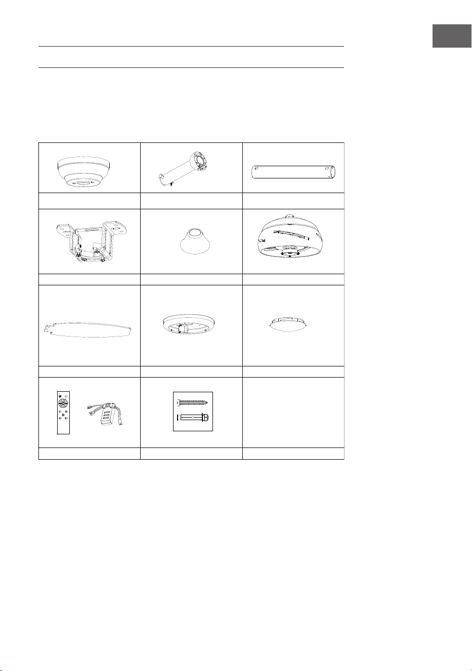
LIEFERUMFANG
Öffnen Sie die Verpackung vorsichtig. Entfernen Sie die Gegenstände aus den
Styroporeinsätzen.
Entfernen Sie das Motorgehäuse und legen Sie es auf einen Teppich oder Styropor,
um Schäden zu vermeiden
zu beenden. Überprüfen Sie anhand der Zubehörliste, ob alle Teile enthalten sind.
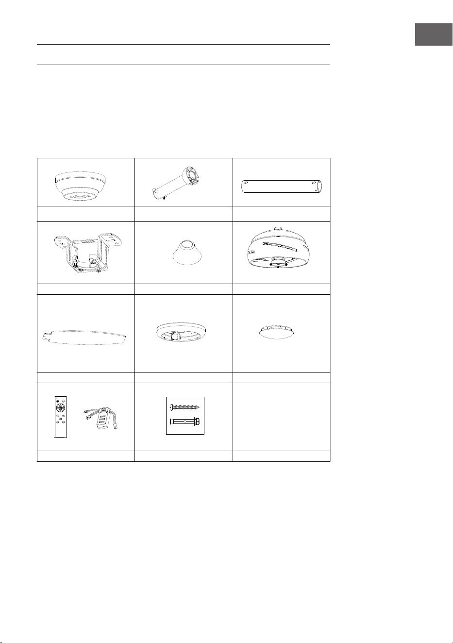
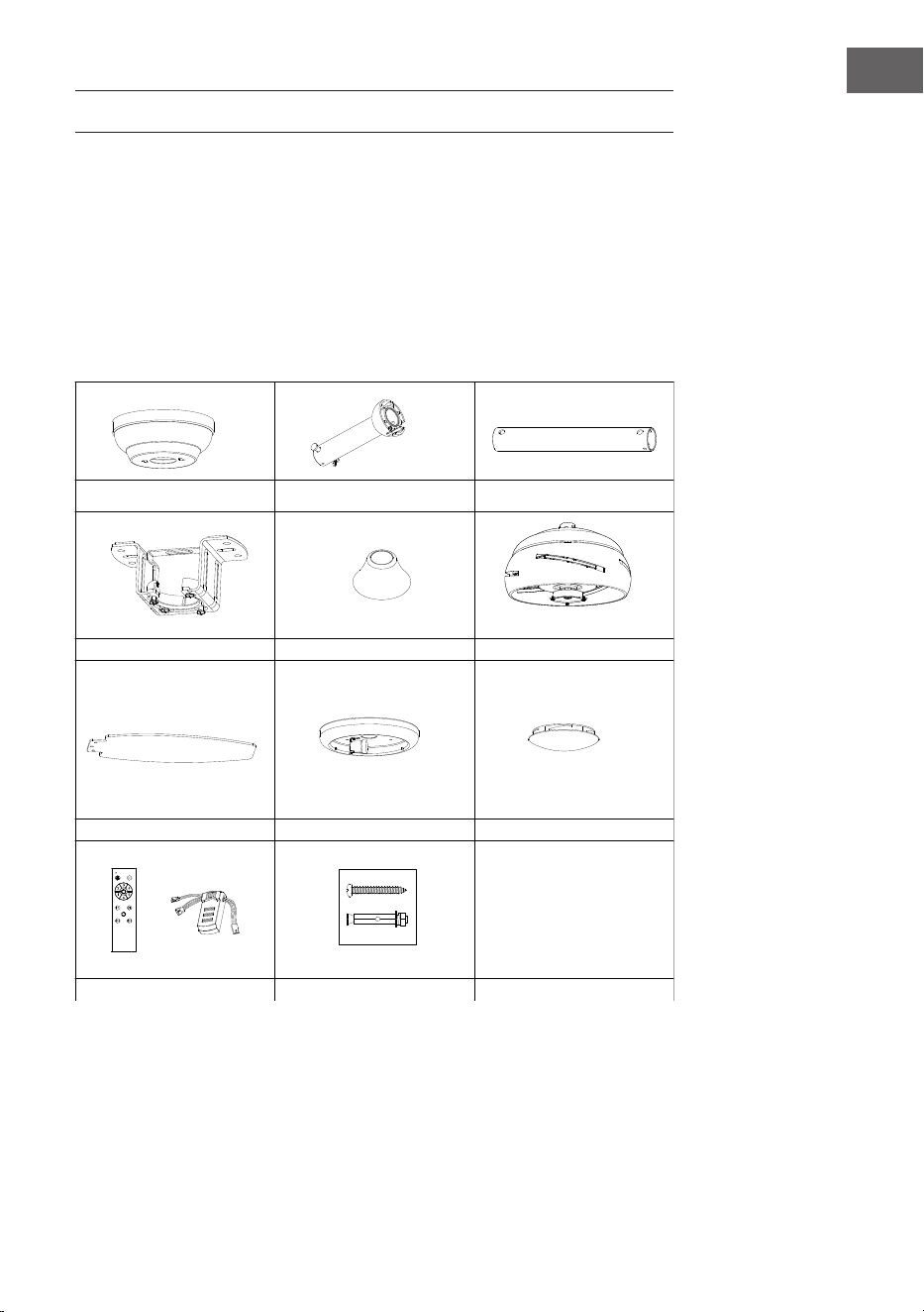
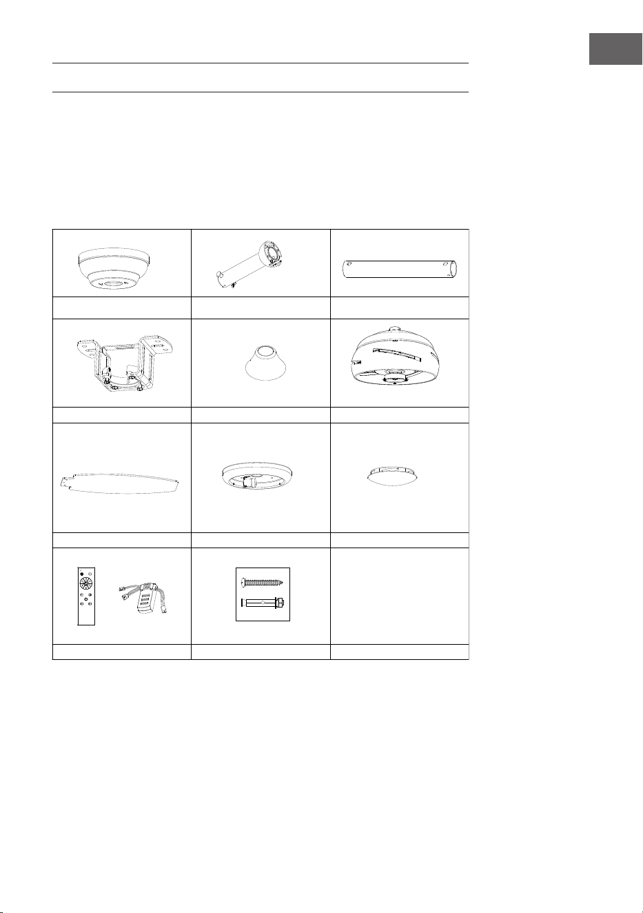
Abdeckung
Befestigungsklammer
Flügel
Fernbedienung
Deckenstange und Hängekugel
Dekorative Abdeckungen
Schrauben und Dübel
Schraubenpackung
Glasschirm
Deckenstange
Motor
6
DE
INSTALLATION
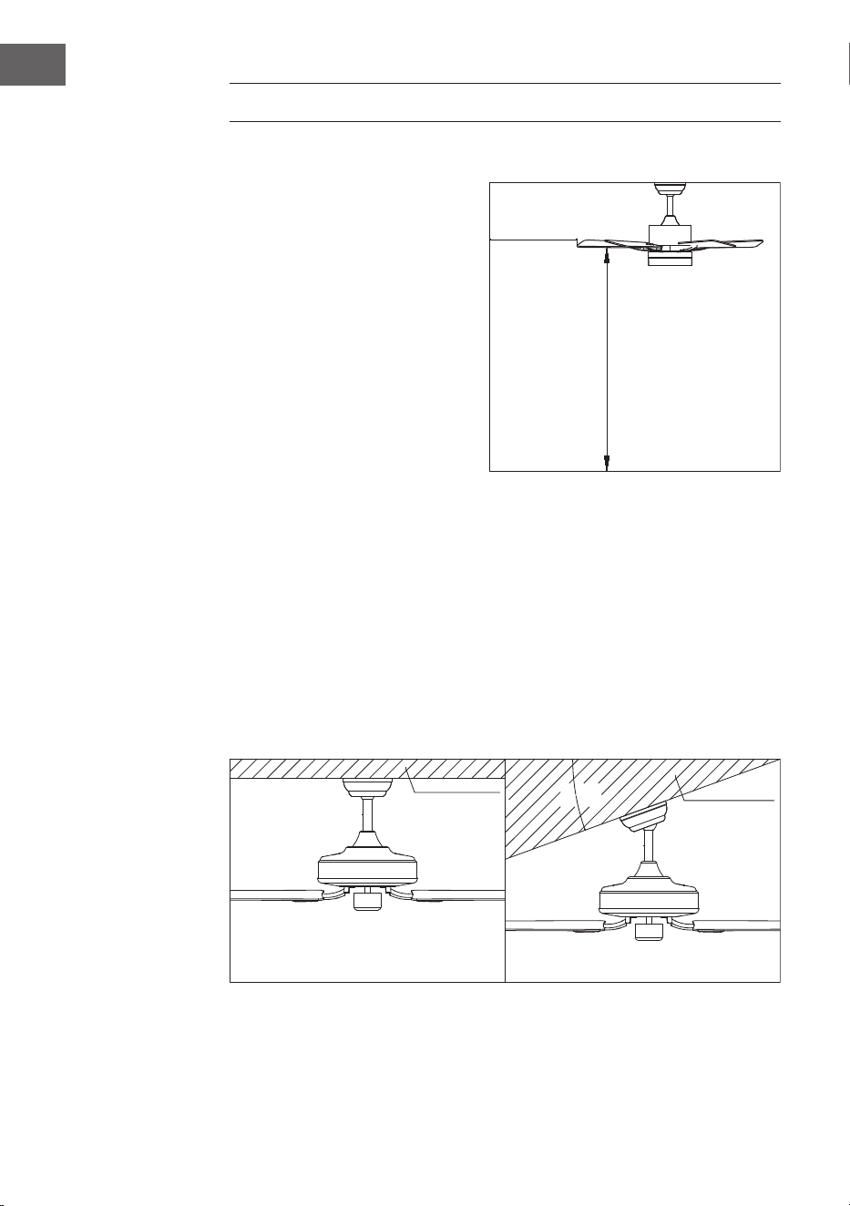
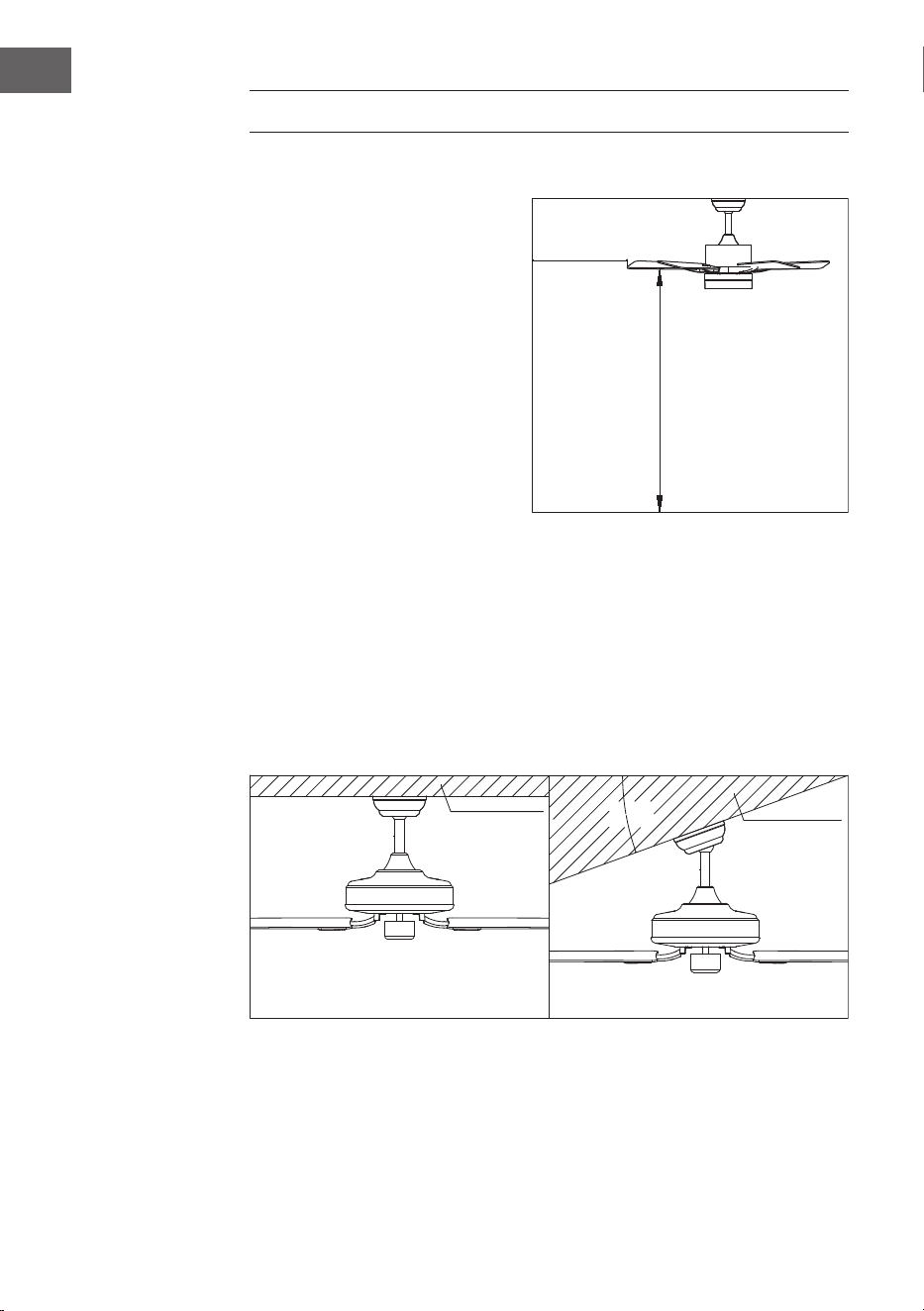
Vorbereitung der Installation
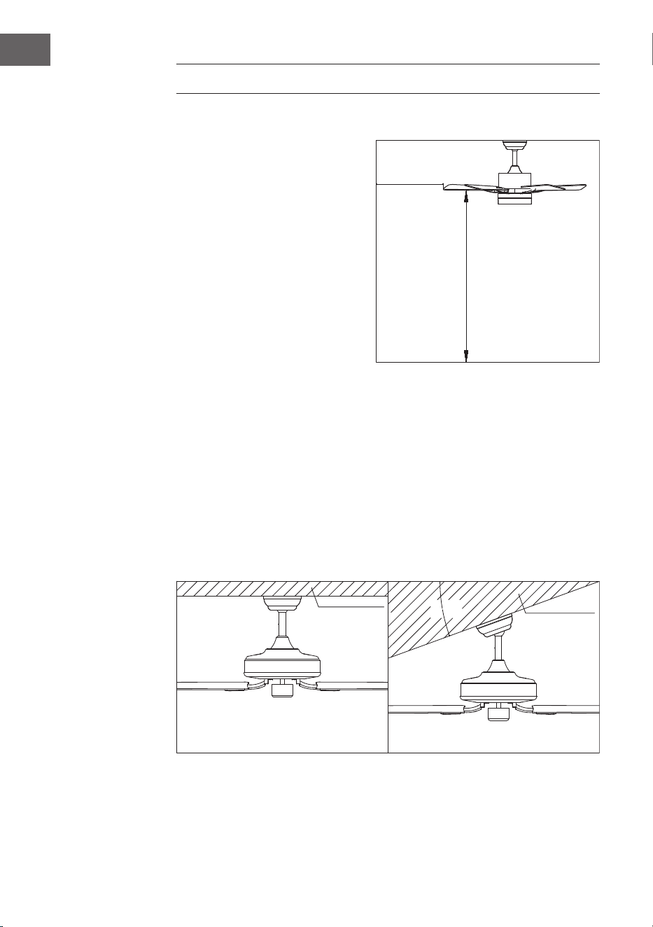
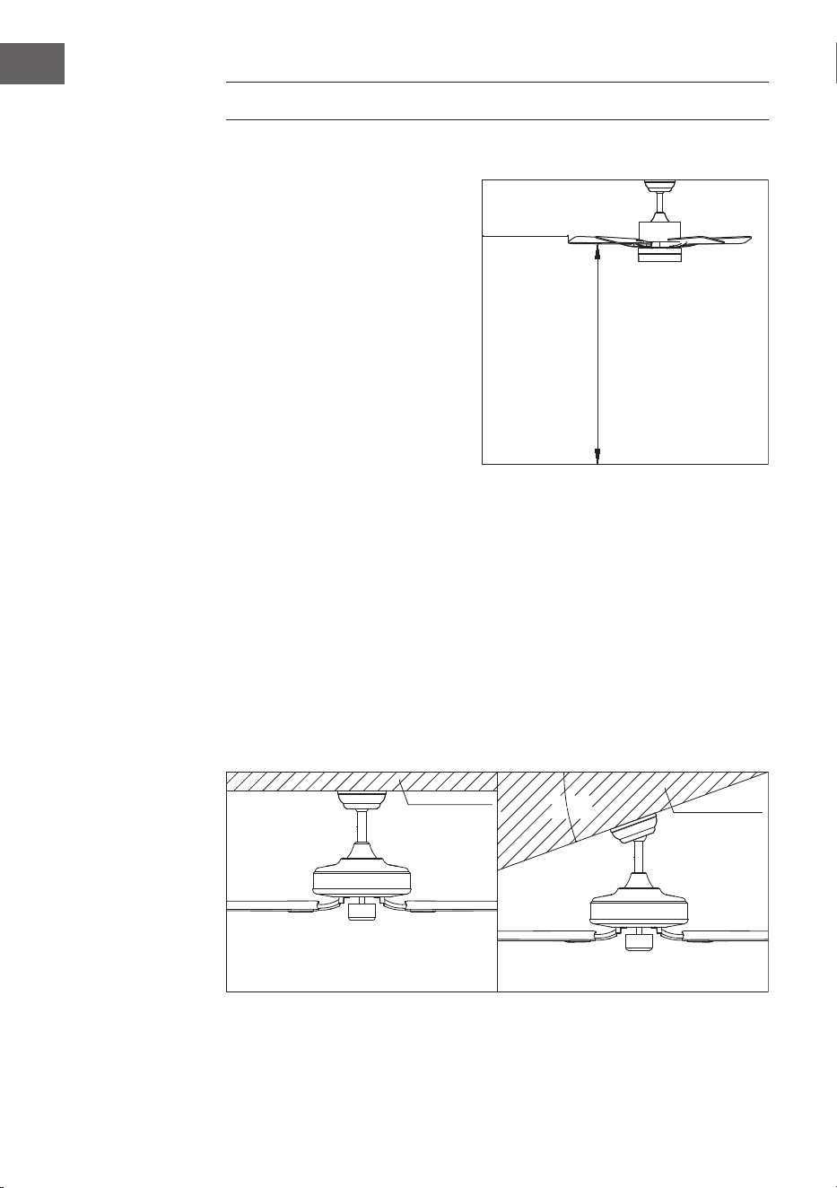
Um Verletzungen und Schäden
zu vermeiden, stellen Sie sicher,
dass die Flügel in einem Abstand
von 2,3 m vom Boden und 76 cm
von Wänden oder Hindernissen
aufgehängt werden können.
Vergewissern Sie sich, dass der
Anschlusskasten sicher an der
Gebäudestruktur befestigt ist und
das volle Gewicht des Ventilators
tragen kann.
Den Installationsort des Ventilators vorbereiten
Installation der Fallstange
Dieser Ventilator kann mit einer Deckenstange an einer normalen oder gewölbten
Decke montiert werden.
Die Aufhängelänge kann durch Verwendung einer längeren Deckenstange
vergrößert werden.
Zur Installation benötigt: Schraubenzieher, Schlitzschraubendreher, verstellbare
Zange oder Schraubenschlüssel, Trittleiter, Drahtschneider und Isolierband.
20°
76 cm von der
Wand oder
dem nächst-
gelegenen
Hindernis
2,3 m
Flügel zum Boden
Standard-
Montage
Die Standardmontage hängt mit
einer Deckenstange von der Decke
Bei einer gewölbten oder schrägen
Decken wird eine schräge Montage
empfohlen.
Stützstrebe
Stützstrebe

7
DE
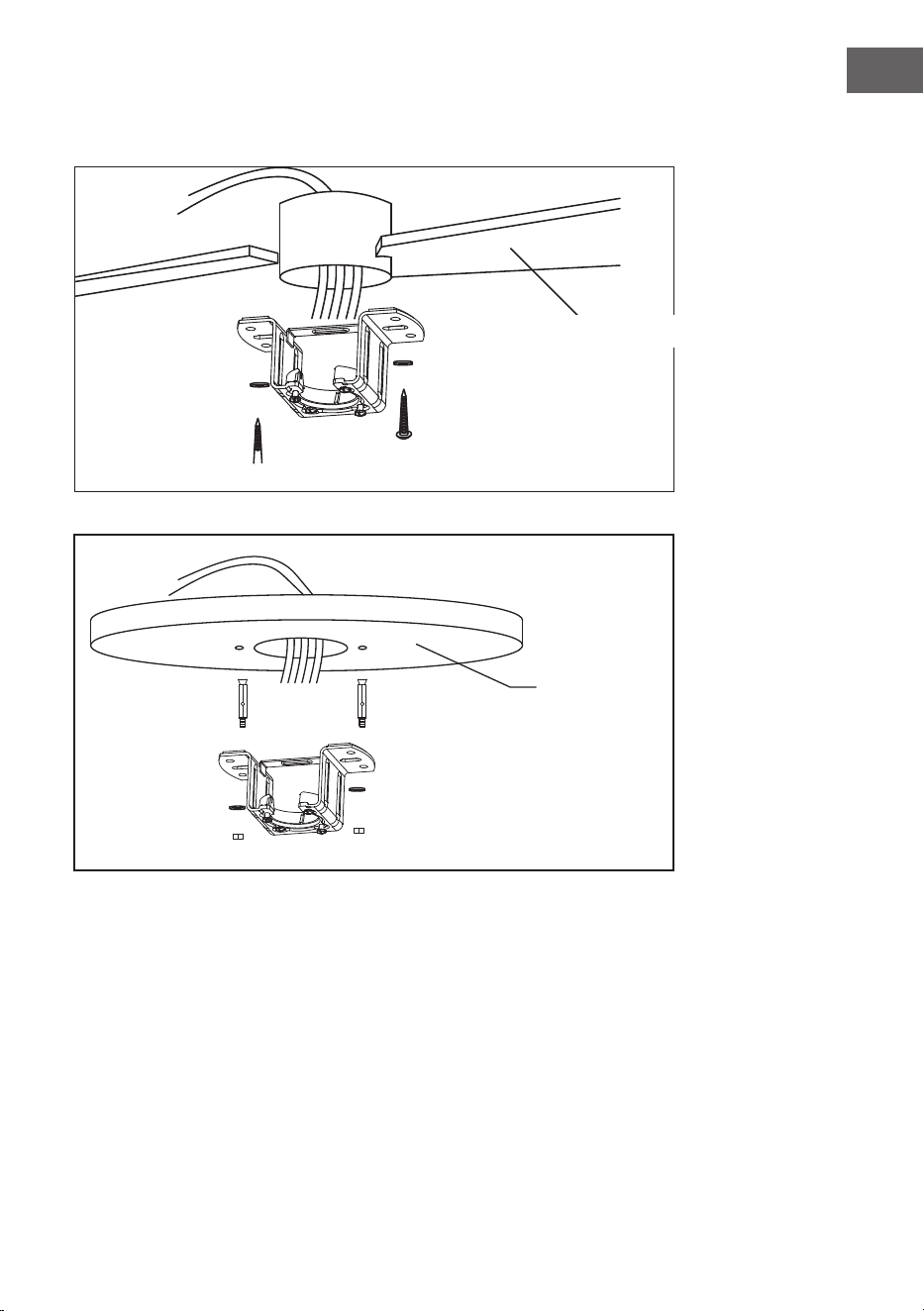
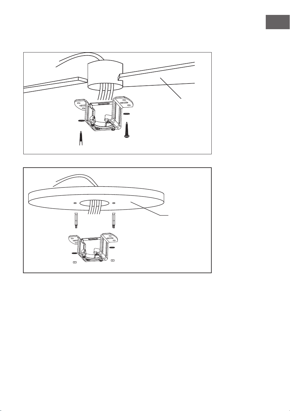
Anbringen der Befestigungsklammer
Bohren Sie ein ⌀8-mm-Loch in die Betondecke und setzen Sie die Dübel und
Schrauben ein.
Richten Sie die Halterung an der Bohrung aus und ziehen Sie die Mutter fest.
Holzdecke
Betondecke
8
DE
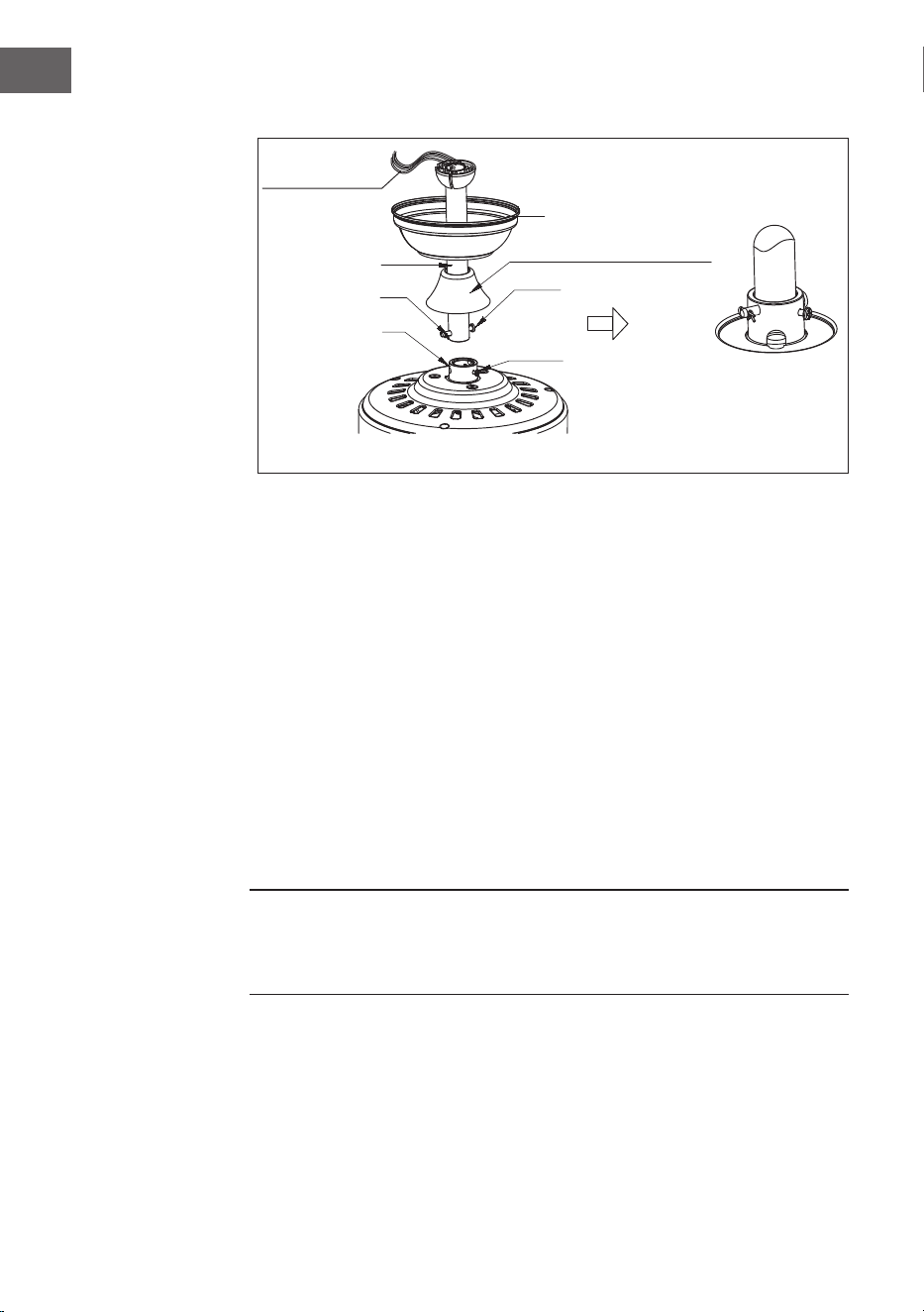
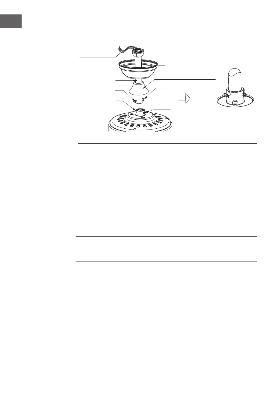
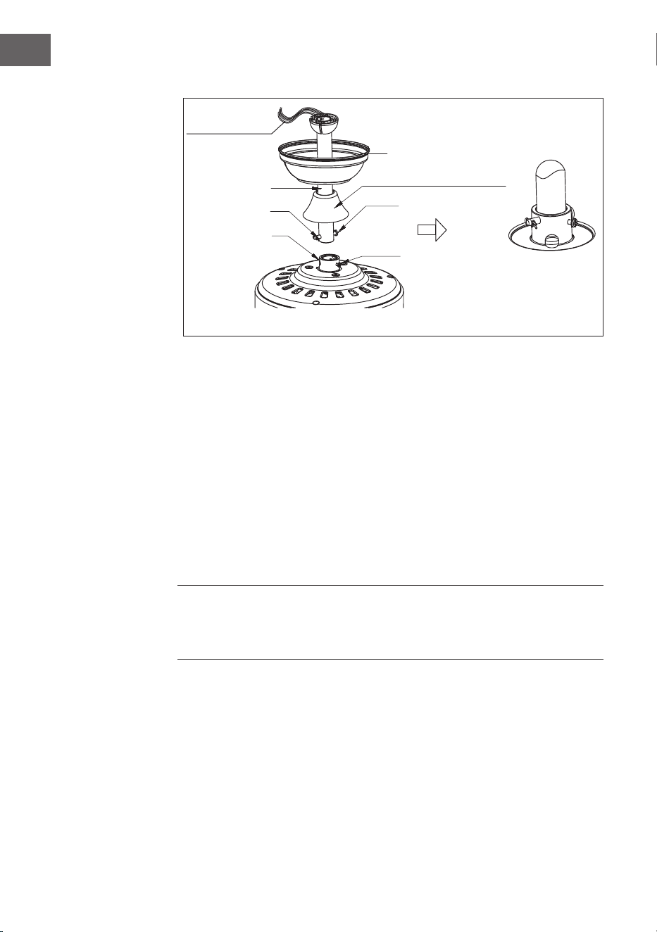
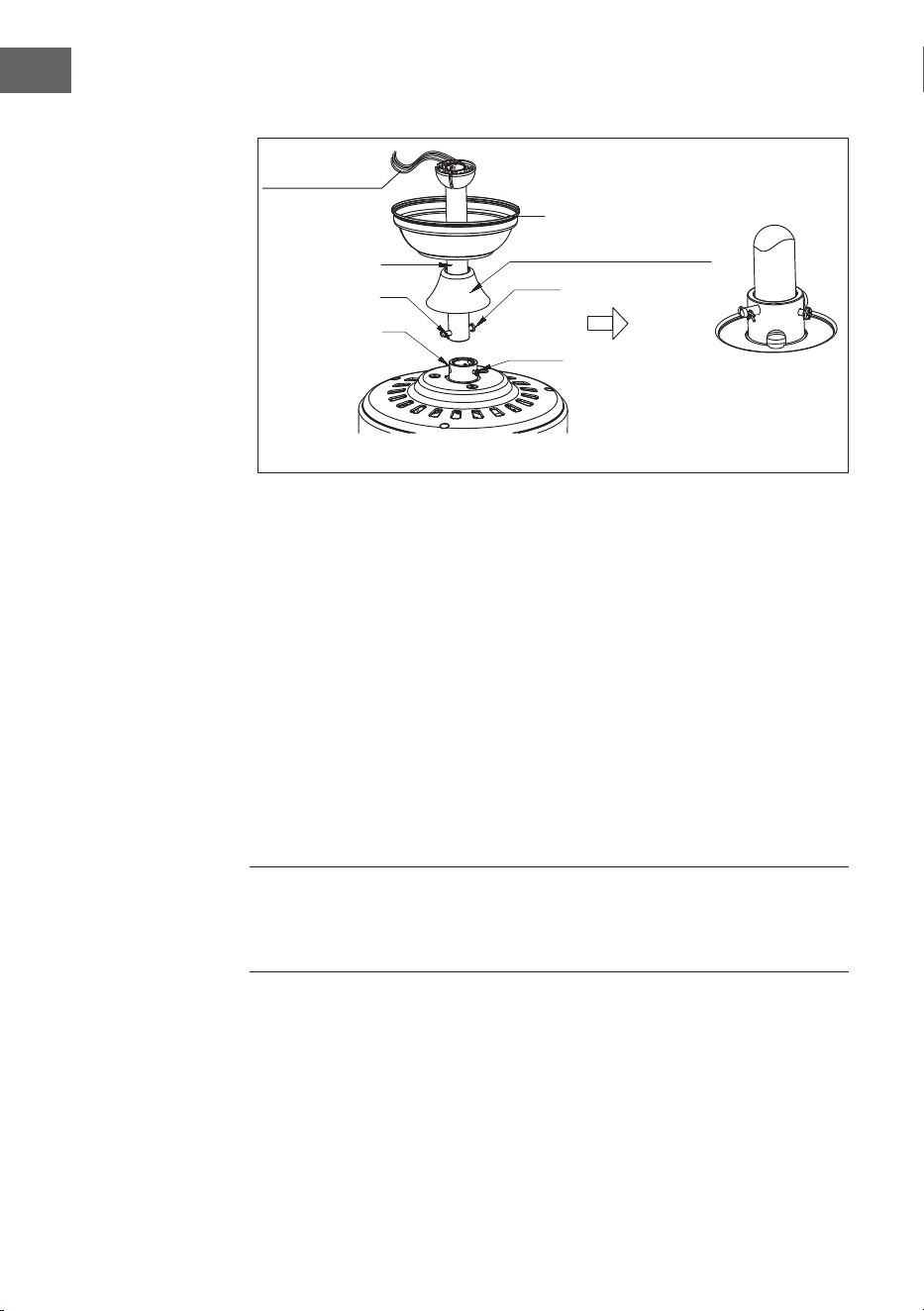
Zusammenbau und Aufhängung des Ventilators
Elektrische
Verkabelung
Abdeckung
Anschlagstift
Dekorative
Abdeckungen
Bügel-
Stellschraube
Adapter
R-Clip
Schlitz für
Aufhängkugel
• Wenn Sie die Aufhängelänge Ihres Ventilators verlängern möchten, müssen
Sie die Aufhängekugel von der mitgelieferten 6-Zoll-Stange entfernen, um
sie mit einer längeren Stange (im Lieferumfang enthalten) zu verwenden.
(Wenn Sie die 6-Zoll-Stange verwenden möchten, fahren Sie bitte mit den
Anweisungen unten fort)
• Um die Aufhängekugel zu entfernen, lösen Sie die Stellschraube an der
Aufhängekugel und entfernen Sie den Stift und den Clip. Schieben Sie die
Aufhängekugel nach unten und entfernen Sie den Anschlagstift.
• Schieben Sie die Aufhängekugel von der ursprünglichen Stange A und
schieben Sie sie an der längeren Stange B hinunter (beachten Sie, dass die
Stange oben ein Loch für die Stellschraube hat; verwenden Sie dieses Loch,
wenn Sie die Stellschraube einstellen).
• Stecken Sie den Anschlagstift in das obere Ende der längeren Deckenstange
und schieben Sie die Aufhängekugel nach oben.
• Vergewissern Sie sich, dass der Anschlagstift mit den Schlitzen an
der Innenseite der Aufhängekugel übereinstimmt, und ziehen Sie die
Stellschraube fest an.
Tipp: Um das Durchführen der elektrischen Drähte durch die Deckenstange
vorzubereiten, kleben Sie ein kleines Stück Isolierband an die Enden der
elektrischen Drähte - so werden die Drähte zusammengehalten, wenn sie durch
die Stange geführt werden.
• Lösen Sie die Bügel-Stellschraube und die Mutter oben am Motorgehäuse.
Entfernen Sie den Stift und die Klammer von der Deckenstange (falls noch
nicht geschehen). Schieben Sie die Deckenstange durch die Abdeckung.
• Führen Sie die elektrischen Drähte durch die Deckenstange und ziehen Sie die
überschüssige Kabellänge vom oberen Ende der Deckenstange.
• Setzen Sie die Deckenstange in das Motorgehäuse ein. Setzen Sie den
zuvor entfernten Anschlagstift und den Clip wieder ein. Ziehen Sie die
Bügelschrauben und die Mutter fest an. Schieben Sie die Abdeckung auf das
Motorgehäuse herunter.

9
DE
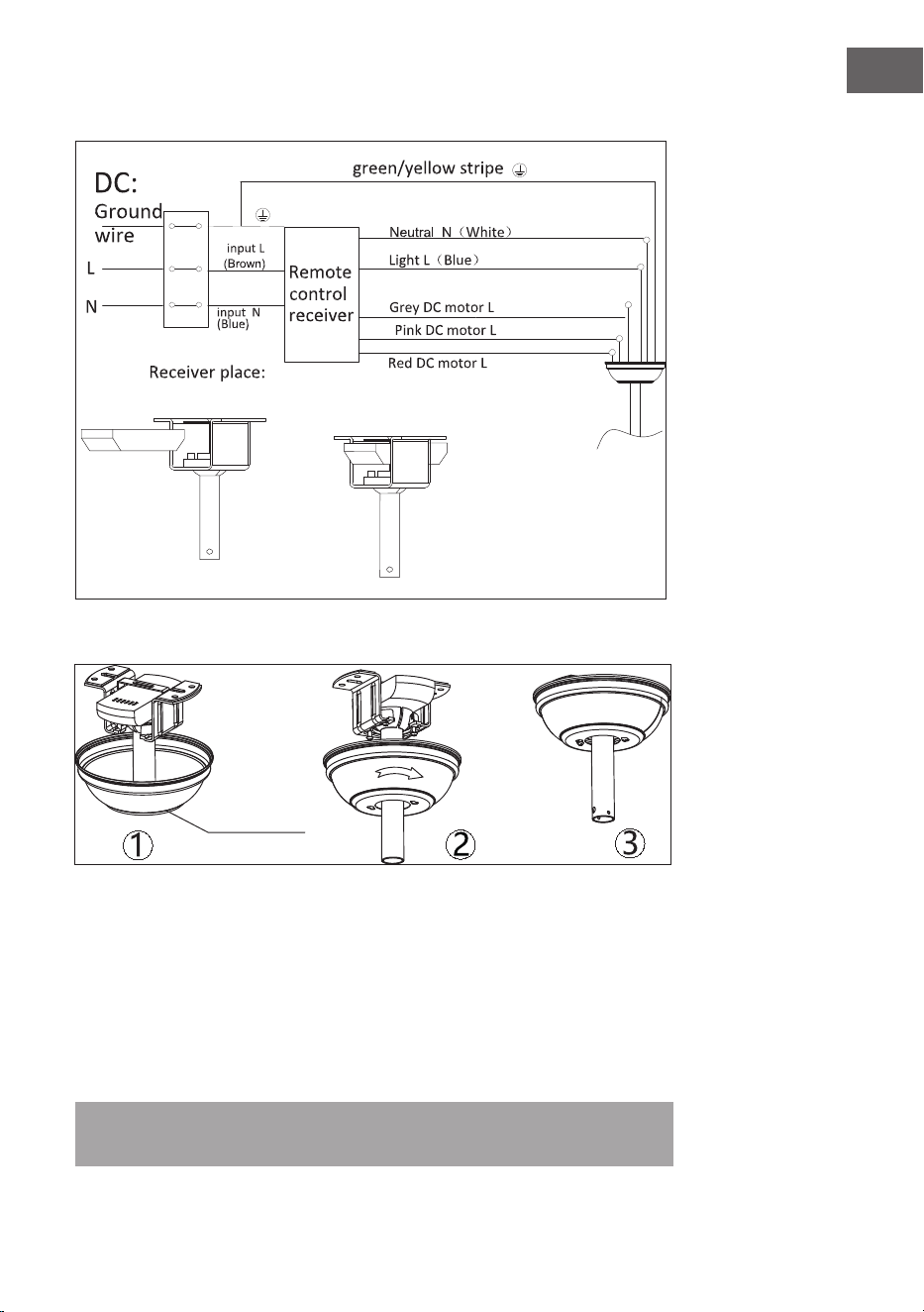
Abdeckung
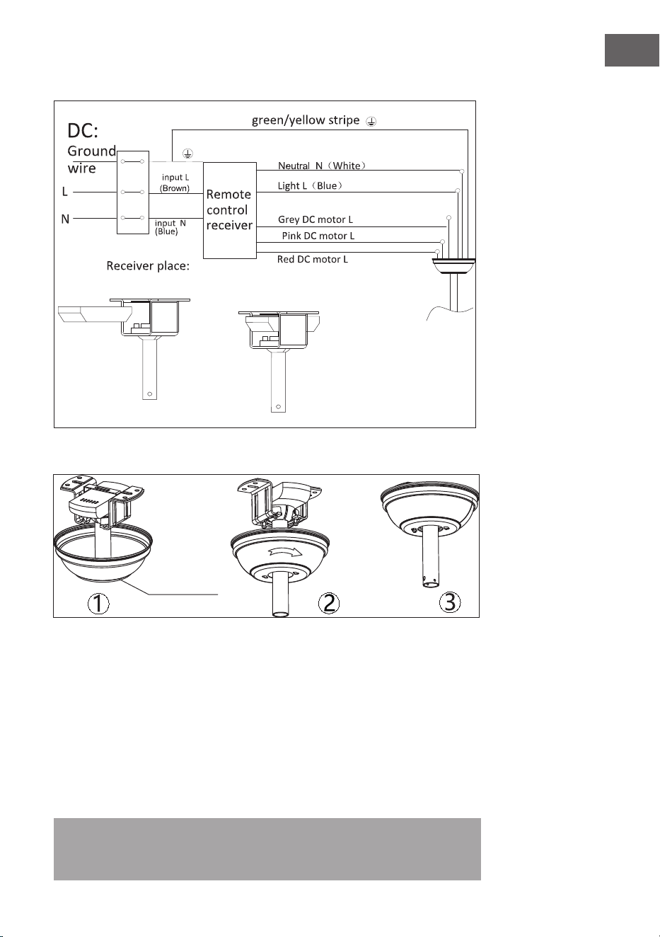
Verkabelung
Montage der Abdeckung
ok
Heben Sie die Abdeckung zur Aufhängung und richten Sie die gelösten Schrauben
in der Halterung an den Schlitzen der Abdeckung aus. Drehen Sie die Abdeckung
zum Fixieren. Setzen Sie die Schrauben wieder ein und ziehen Sie alle Schrauben
mit einem Schraubendreher fest.
Wenn die Befestigungsklammer an der Steckdose befestigt ist und den Ventilator
tragen kann, können Sie den Ventilator nun aufhängen. Halten Sie den Ventilator
mit beiden Händen fest. Schieben Sie die Deckenstange durch die Öffnung in der
Aufhängevorrichtung und platzieren Sie die Aufhängekugel auf der Halterung.
Drehen Sie die Aufhängekugel, bis die Schlitze mit der Halterung übereinstimmen.
Hinweis: Lassen Sie sich von einer weiteren Person helfen, die die Leiter
festhält und Ihnen den Ventilator reicht, wenn Sie auf der Leiter stehen.
10
DE
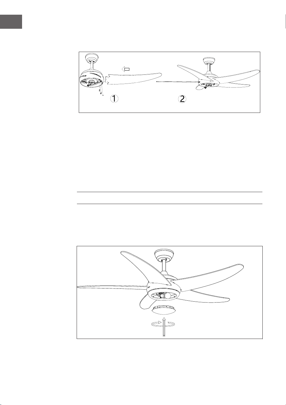
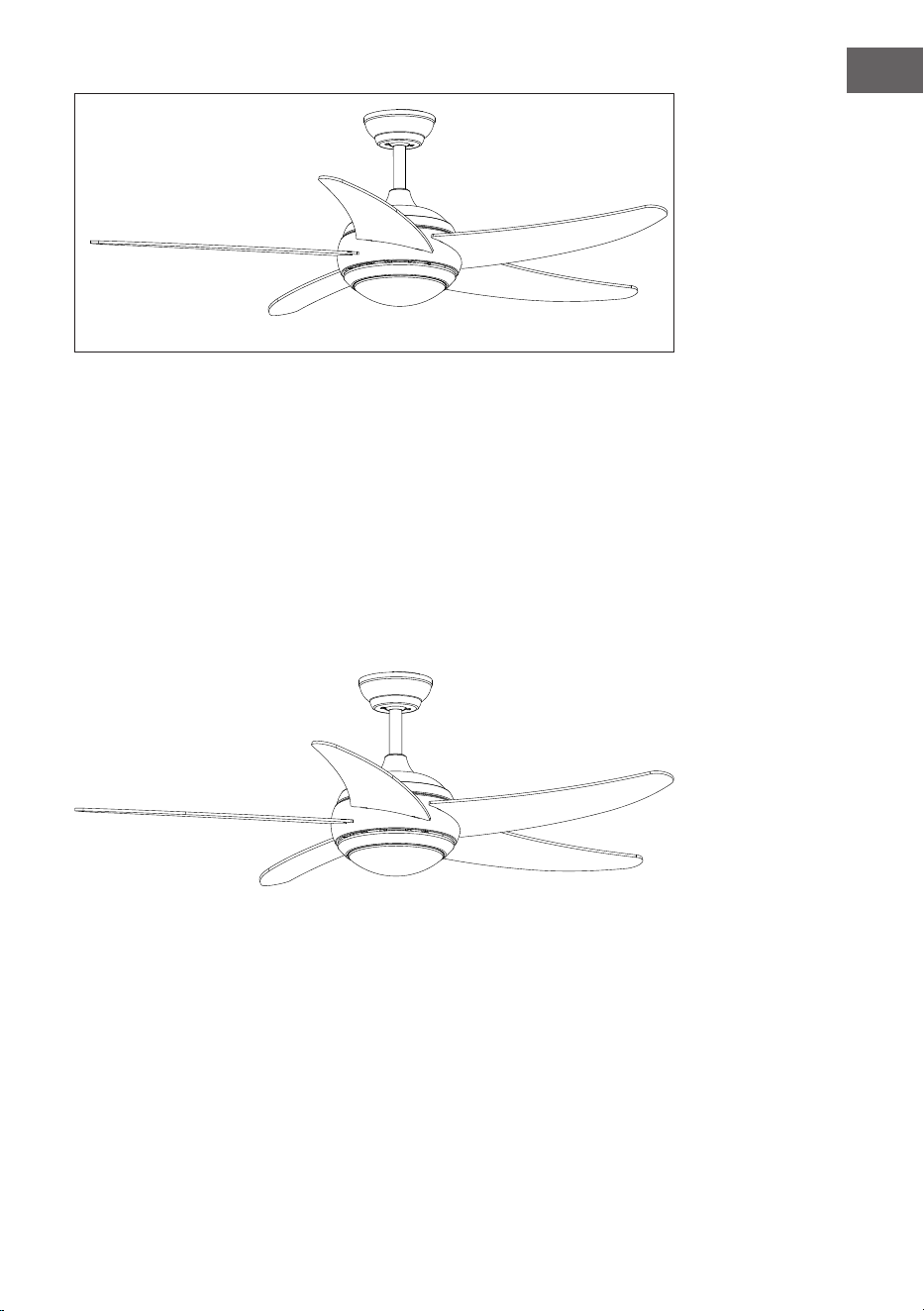
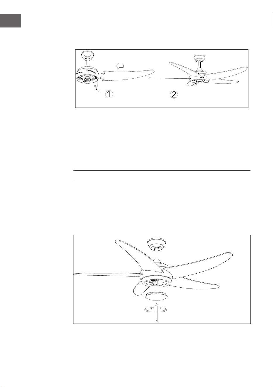
Montage der Flügel
Montage des Lampenschirms
Zeitersparnis: Die Unterlegscheiben für die Flügelschrauben können vor der
Montage der Flügel auf jede Flügelschraube gelegt werden.
Richten Sie die Löcher für die Klingen an den Löchern für die Motorschrauben
aus und ziehen Sie alle Schrauben fest, sobald alle Flügel angebracht sind.
Wiederholen Sie diesen Vorgang mit den übrigen Flügeln, bevor Sie die Schrauben
endgültig befestigen.
Hinweis: Ziehen Sie die Flügelschrauben zweimal an.
Schrauben
der Flügel

11
DE
Montage beendet
Bringen Sie die Abdeckung und den Lampenschirm wieder am LED-Rahmen an
und befestigen Sie sie mit Zierklammern und Schraubenmuttern.

12
DE
INBETRIEBNAHME
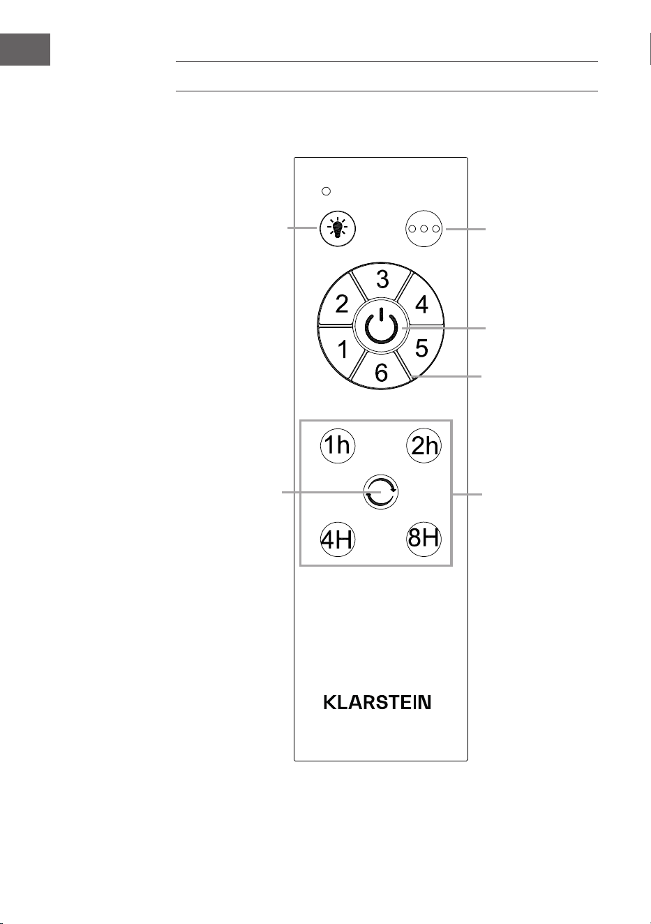
Fernbedienung
Lampenschalter
Drehrichtung
Ventilatorgeschwindigkeit
einstellen
Timer
1 Stunde
2 Stunden
4 Stunden
8 Stunden
Beleuchtungs-
anpassung
Ein/Aus

13
DE
A: Zwischen Sender und Empfänger wird ein Lerncode-Anpassungsmodus
verwendet. Schalten Sie die Stromversorgung innerhalb von 30 Sekunden auf
"ON" und drücken Sie die Taste "FAN ON/OFF" des Senders 5 Sekunden lang.
Nachdem ein langer Piepton ertönt, kann dieser normal geladen werden, das
bedeutet, dass das Lernen erfolgreich war und er normal funktioniert.
Hinweise
• Der Lernmodus wird nicht akzeptiert, nachdem die Stromversorgung länger
als 30 Sekunden eingeschaltet ist.
• Wenn der Sender den Empfänger nicht steuern kann, überprüfen Sie, ob die
Batterie richtig eingesetzt ist oder ob der Batteriestand zu niedrig ist. Prüfen
Sie auf Störungen durch ähnliche elektronische Produkte.
14
DE
SPEZIELLE ENTSORGUNGSHINWEISE FÜR
VERBRAUCHER IN DEUTSCHLAND
Entsorgen Sie Ihre Altgeräte fachgerecht. Dadurch wird gewährleistet, dass die
Altgeräte umweltgerecht verwertet und negative Auswirkungen auf die Umwelt
und menschliche Gesundheit vermieden werden. Bei der Entsorgung sind
folgende Regeln zu beachten:
• Jeder Verbraucher ist gesetzlich verpichtet, Elektro- und
Elektronikaltgeräte (Altgeräte) sowie Batterien und Akkus
getrennt vom Hausmüll zu entsorgen. Sie erkennen die
entsprechenden Altgeräte durch folgendes Symbol der
durchgestrichenen Mülltonne (WEEE-Symbol).
• Sie haben Altbatterien und Altakkumulatoren, die nicht vom Altgerät
umschlossen sind, sowie Lampen, die zerstörungsfrei aus dem Altgerät
entnommen werden können, vor der Abgabe an einer Entsorgungsstelle vom
Altgerät zerstörungsfrei zu trennen.
• Bestimmte Lampen und Leuchtmittel fallen ebenso unter das Elektro- und
Elektronikgesetz und sind dementsprechend wie Altgeräte zu behandeln.
Ausgenommen sind Glühbirnen und Halogenlampen. Entsorgen Sie
Glühbirnen und Halogenlampen bitte über den Hausmüll, sofern sie nicht das
WEEE-Symbol tragen.
• Jeder Verbraucher ist für das Löschen von personenbezogenen Daten auf dem
Elektro- bzw. Elektronikgerät selbst verantwortlich.
Rücknahmepicht der Vertreiber
Vertreiber mit einer Verkaufsäche für Elektro- und Elektronikgeräte von
mindestens 400 Quadratmetern sowie Vertreiber von Lebensmitteln mit einer
Gesamtverkaufsäche von mindestens 800 Quadratmetern, die mehrmals im
Kalenderjahr oder dauerhaft Elektro- und Elektronikgeräte anbieten und auf dem
Markt bereitstellen, sind verpichtet,
1 bei der Abgabe eines neuen Elektro- oder Elektronikgerätes an einen Endnutzer
ein Altgerät des Endnutzers der gleichen Geräteart, das im Wesentlichen die
gleichen Funktionen wie das neue Gerät erfüllt, am Ort der Abgabe oder in
unmittelbarer Nähe hierzu unentgeltlich zurückzunehmen und
2 auf Verlangen des Endnutzers Altgeräte, die in keiner äußeren Abmessung
größer als 25 Zentimeter sind, im Einzelhandelsgeschäft oder in unmittelbarer
Nähe hierzu unentgeltlich zurückzunehmen; die Rücknahme darf nicht an den
Kauf eines Elektro- oder Elektronikgerätes geknüpft werden und ist auf drei
Altgeräte pro Geräteart beschränkt.

15
DE
• Bei einem Vertrieb unter Verwendung von Fernkommunikationsmitteln
ist die unentgeltliche Abholung am Ort der Abgabe auf Elektro- und
Elektronikgeräte der Kategorien 1, 2 und 4 gemäß § 2 Abs. 1 ElektroG, nämlich
„Wärmeüberträger“, „Bildschirmgeräte“ (Oberäche von mehr als 100 cm²)
oder „Großgeräte“ (letztere mit mindestens einer äußeren Abmessung
über 50 Zentimeter) beschränkt. Für andere Elektro- und Elektronikgeräte
(Kategorien 3, 5, 6) ist eine Rückgabemöglichkeit in zumutbarer Entfernung
zum jeweiligen Endnutzer zu gewährleisten.
• Altgeräte dürfen kostenlos auf dem lokalen Wertstoffhof oder in folgenden
Sammelstellen in Ihrer Nähe abgegeben werden: www.take-e-back.de
• Für Elektro- und Elektronikgeräte der Kategorien 1, 2 und 4 bieten wir auch die
Möglichkeit einer unentgeltlichen Abholung am Ort der Abgabe. Beim Kauf
eines Neugeräts haben Sie die Möglichkeit, eine Altgerätabholung über die
Webseite auszuwählen.
• Batterien können überall dort kostenfrei zurückgegeben werden, wo sie
verkauft werden (z. B. Super-, Bau-, Drogeriemarkt). Auch Wertstoff- und
Recyclinghöfe nehmen Batterien zurück. Sie können Batterien auch per Post
an uns zurücksenden. Altbatterien in haushaltsüblichen Mengen können Sie
direkt bei uns von Montag bis Freitag zwischen 08:00 und 16:00 Uhr unter der
folgenden Adresse unentgeltlich zurückgeben:
Chal-Tec Fulllment GmbH
Norddeutschlandstr. 3
47475 Kamp-Lintfort
• Wichtig zu beachten ist, dass Lithiumbatterien aus Sicherheitsgründen vor der
Rückgabe gegen Kurzschluss gesichert werden müssen (z. B. durch Abkleben
der Pole).
• Finden sich unter der durchgestrichenen Mülltonne auf der Batterie zusätzlich
die Zeichen Cd, Hg oder Pb ist das ein Hinweis darauf, dass die Batterie
gefährliche Schadstoffe enthält (»Cd« steht für Cadmium, »Pb« für Blei und
»Hg« für Quecksilber).
Hinweis zur Abfallvermeidung
Indem Sie die Lebensdauer Ihrer Altgeräte verlängern, tragen Sie dazu bei,
Ressourcen ezient zu nutzen und zusätzlichen Müll zu vermeiden. Die
Lebensdauer Ihrer Altgeräte können Sie verlängern, indem Sie defekte Altgeräte
reparieren lassen. Wenn sich Ihr Altgerät in gutem Zustand bendet, könnten Sie
es spenden, verschenken oder verkaufen.
16
DE
HINWEISE ZUR ENTSORGUNG
Wenn es in Ihrem Land eine gesetzliche Regelung
zur Entsorgung von elektrischen und elektronischen
Geräten gibt, weist dieses Symbol auf dem Produkt oder
auf der Verpackung darauf hin, dass dieses Produkt
nicht im Hausmüll entsorgt werden darf. Stattdessen
muss es zu einer Sammelstelle für das Recycling von
elektrischen und elektronischen Geräten gebracht
werden. Durch regelkonforme Entsorgung schützen
Sie die Umwelt und die Gesundheit Ihrer Mitmenschen
vor negativen Konsequenzen. Informationen zum
Recycling und zur Entsorgung dieses Produkts,
erhalten Sie von Ihrer örtlichen Verwaltung oder Ihrem
Hausmüllentsorgungsdienst.
Dieses Produkt enthält Batterien. Wenn es in Ihrem
Land eine gesetzliche Regelung zur Entsorgung von
Batterien gibt, dürfen die Batterien nicht im Hausmüll
entsorgt werden. Informieren Sie sich über die örtlichen
Bestimmungen zur Entsorgung von Batterien. Durch
regelkonforme Entsorgung schützen Sie die Umwelt
und die Gesundheit Ihrer Mitmenschen vor negativen
Konsequenzen.
HERSTELLER
Chal-Tec GmbH, Mühlenstraße 25, 10243 Berlin, Deutschland.
Kontakt: [email protected]
17
DE
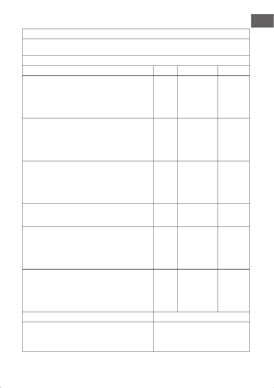
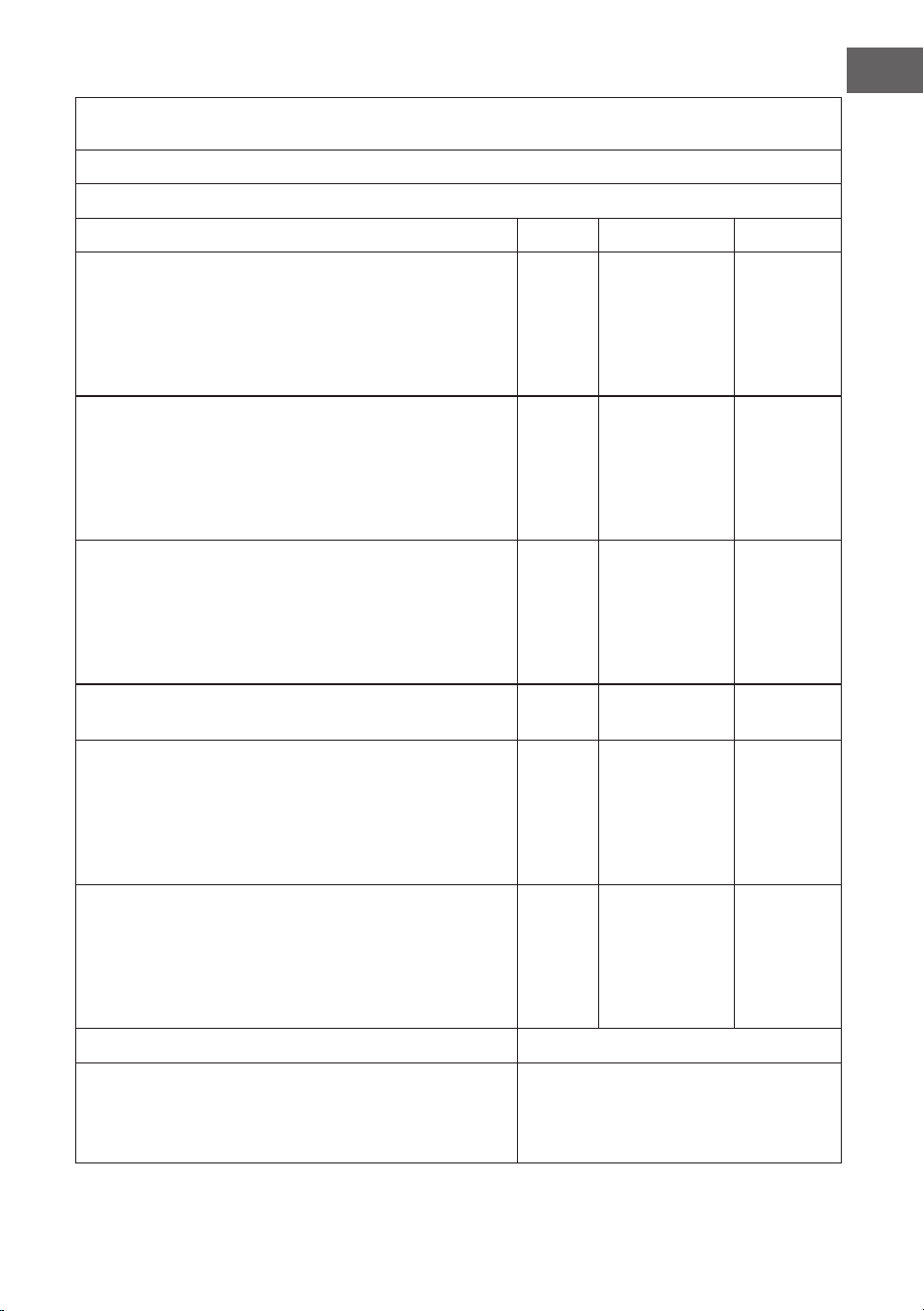
Produktinformationspichten gemäß VERORDNUNG (EU) Nr. 206/2012
Informationen zur Identizierung des Modells/der Modelle, auf das/die sich die Informationen
beziehen
10048081, 10048082, 10048083, 10048084 - Klarstein Bolero Deckenventilator
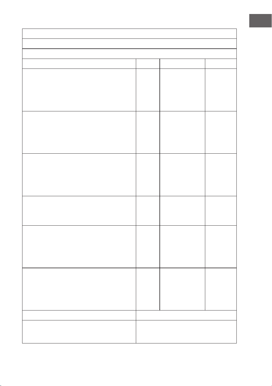
Beschreibung Symbol Wert Einheit
Maximaler Ventilatordurchsatz F Stufe 1: 56,8
Stufe 2: 85,2
Stufe 3: 116,4
Stufe 4: 139,8
Stufe 5: 156,3
Stufe 6: 170,6
m3/min
Eingangsleistung Ventilator P Stufe 1: 4,5
Stufe 2: 7,6
Stufe 3: 12,5
Stufe 4: 18,5
Stufe 5: 25,1
Stufe 6: 35,0
W
Servicewert SV Stufe 1: 12,7
Stufe 2: 11,3
Stufe 3: 9,3
Stufe 4: 7,5
Stufe 5: 6,2
Stufe 6: 4,9
(m3/min)/W
Stromverbrauch im Standby-Modus mit LED-Lampe Typ
DC
Stromverbrauch im Standby-Modus mit LED-Lampe Typ AC
PSB 0,5
0,34
W
Geräuschpegel Ventilator LWA Stufe 1: 33,6
Stufe 2: 34,1
Stufe 3: 36,6
Stufe 4: 39,7
Stufe 5: 43,2
Stufe 6: 47,0
dB(A)
Maximale Luftgeschwindigkeit c Stufe 1: 1,0
Stufe 2: 1,5
Stufe 3: 1,8
Stufe 4: 2,2
Stufe 5: 2,4
Stufe 6: 2,8
m/s
Messstandard für den Servicewert IEC 60879:2019
Kontaktangaben für weitere Informationen Chal-Tec GmbH
Mühlenstraße 25
10243 Berlin
Deutschland

19
EN
TECHNICAL DATA
Article number 10048081, 10048082, 10048083, 10048084
Power supply 220-240 V~ 50/60 Hz
Fan power 40 W
Maximum volume ow 171 m
3
/min
Lamp type E27 lamp holder, Max: 60 W
Technical Data 19
Safety Instructions 20
Scope of Supply 21
Installation 22
Use and Operation 28
Disposal Considerations 30
Manufacturer & Importer (UK) 30
Dear Customer,
Congratulations on purchasing this equipment. Please
read this manual carefully and take care of the following
hints on installation and use to avoid technical damages.
Any failure caused by ignoring the items and cautions
mentioned in the operation and installation instructions
are not covered by our warranty and any liability. Scan
the QR code to get access to the latest user manual and
more product information.
CONTENTS

20
EN
SAFETY INSTRUCTIONS
• Never attach the fan to a power point,but to the ceiling itself.
• The minimum distance between the blades of the fan and the oor must be
more than 2.3 m. The minimum carrying capacity of the hook from which the
fan is hung must be 100 kg.
• Make sure to install all poles disconnection switch having a contact separation
of at least 3 mm between poles in the supply wiring to the ceiling fan.
• The model or type reference of luminaries which may be installed in fans
which are constructed for his purpose.
• Switch off the power before connecting.
• The electrical wiring must be in accordance with the local regulation.
• The fan must be properly earthed to avoid the risk of electric shocks.
• Never mount the fan in a moist or wet room.
• Be careful when working near the rotor blades.
• This device may be only used by children 8 years old or older and persons with
limited physical, sensory and mental capabilities and / or lack of experience
and knowledge, provided that they have been instructed in use of the device
by a responsible person who understands the associated risks.
• Children shall not be permitted to play with the appliance.
• Cleaning and maintenance shall not be carried out by children without
supervision.
• Ensure that the fan is switched off from the supply mains before removing the
guard.
• Take precautions to avoid the back-ow of gases into the room from the open
ue of gas or other fuel-burning appliances (for duct and partition fans).
Note: Always have your fan installed by someone who is knowledgeable about
electrical wiring.
21
EN
SCOPE OF SUPPLY
Carefully open the packaging. Remove items from Styrofoam inserts.
Remove motor housing and place on carpet or Styrofoam to avoid damage
to nish. Check against parts inventory that all parts have been included.
canopy
hanger bracket
blade
remote control
downrod and hanging ball
decorative covers
screws and dowls
spiral package
glass shade
downrod
motor
22
EN
INSTALLATION
Installation prepraton
To prevent personal injury and
damage, ensure that the hanging
location allows the blades a
clearance of 2.3m from the
oor and 76cm from any wall or
obstruction.
Be sure the outlet box is securely
attached to the building structure
and can support the full weight of
the fan.
Preparing the Fan Site
Downrod Installation
This fan can be mounted with a downdrod on a normal or vaulted ceiling.
The hanging length can be extended by a longer downdrod.
Installation requires these tools: Screwdriver, at-head screwdriver, adjustable
pliers or wrench, stepladder, wire cutters, and rated electrical tape.
20°
76 cm
from wall
or nearest
obstructions
2.3 m
blades to oor
standard
mounting
style
Standard Mounting hangs from the
ceiling by a downrod
Angled Mounting recommended for
a vaulted or angled ceiling.
support brace
support brace
23
EN
Installing the Hanger Bracket
Please drill ⌀8-mm hole on the concrete ceiling, and insert the the dowels and the
bolts.
Align bracket with the hole, then tighten with nut.
wood ceiling
concrete ceiling
24
EN
Assembling and Hanging the Fan
electical wiring
canopy
stop pin
decorative covers
yoke set screw
adapter
R clip
hanging ball
slot
• If you wish to extend the hanging length of your fan, you must remove the
hanging ball from the 6 inch downrod provided to use with an extended
downrod (included) . (If you wish to use the 6 inch downrod, please proceed
to instructions below.)
• To remove hanging ball, loose set screw on hanging ball and remove pin
and clip. Lower hanging ball and remove stop pin. Slide hanging ball off the
original downrod A, and slide it down the longer downrod B (the top of the
downrod should be noted as having a set screw hole; use this hole when
setting the set screw).
• Insert stop pin into top of extended downrod and raise hanging ball.
• Be sure stop pin aligns with slots on the inside of the hanging ball, tighten set
screw securely.
Tip: To prepare for threading electrical wires through downrod, apply small piece
of electrical tape to the ends of electrical wires-this will keep the wires together
when threading them through the downrod.
• Loosen yoke set screws and nut at top of motor housing. Remove pin and
clip from downrod (if you have not already done so). Slide downrod through
canopy.
• Tread electrical wires through downrod and pull extra wire slack from the
upper end of the downrod.
• Place downrod into the motor housing yoke. Insert the stop pin and clip that
were previously removed. Tighten yoke set screws and nut securely. Lower
the canopy to motor housing.
25
EN
canopy
Wiring
Canopy assembly
ok
Raise canopy to hanging bracket, aligning loosened screws in hanging bracket
with slotted holes in canopy. Twist canopy to lock. Re-insert screws and secured all
screws with screwdriver.
With the hanging bracket secured to the outlet box and able to support to fan,
you are now ready to hang your fan. Grab the fan rmly with two hands. Slide
downrod through opening in hanging bracket and let hanging ball rest on the
hanging bracket. Turn the hanging ball slot until it lines up with the hanging
bracket tab.
Note: Seek the help of another person to hold the stepladder in place and to lift
the fan up to you once you are set on the ladder.

26
EN
Blade assembly
Lamp shade assembly
Time Saver: Washers for blade screws can be set on each blade screw prior to
installing blades.
Align blade holes with motor screw holes, Securing tighten all the screws once
all the blades are attached. Before securing screws permanently, repeat with
remaining blade arms.
Note: Tighten blade arm screws twice.
blade arm
screws
27
EN
Assembly nished
Restore the cover and the lamp shade back to the LED pan, and secure them with
decorative clips and bolt nuts.

28
EN
USE AND OPERATION
Remote control
lamp switch
spinning direction
fan speed
regulation
timer
1 hour
2 hours
4 hours
8 hours
lamp conversion
On/Off

29
EN
A: Learning code matching mode is used between emitter and receiver. Turn the
power supply "ON" within 30 seconds and press the emitter "FAN ON/OFF" button
for 5 seconds. It can load normally after hearing a long "bee" sound, which means
the learning is successful and it works normally.
Notes
• The learning mode is not accepted after turning on the power supply for 30
seconds.
• If the transmitter cannot control the receiver, check that the battery is
installed correctly, or that the battery level too low. Check for interference
from similar electronic products.

30
EN
DISPOSAL CONSIDERATIONS
If there is a legal regulation for the disposal of electrical
and electronic devices in your country, this symbol on the
product or on the packaging indicates that this product
must not be disposed of with household waste. Instead,
it must be taken to a collection point for the recycling
of electrical and electronic equipment. By disposing of
it in accordance with the rules, you are protecting the
environment and the health of your fellow human beings
from negative consequences. For information about the
recycling and disposal of this product, please contact your
local authority or your household waste disposal service.
This product contains batteries. If there is a legal
regulation for the disposal of batteries in your country,
the batteries must not be disposed of with household
waste. Find out about local regulations for disposing
of batteries. By disposing of them in accordance with
the rules, you are protecting the environment and the
health of your fellow human beings from negative
consequences.
MANUFACTURER & IMPORTER (UK)
Chal-Tec GmbH, Mühlenstraße 25, 10243 Berlin, Germany.
Contact: [email protected]

31
EN
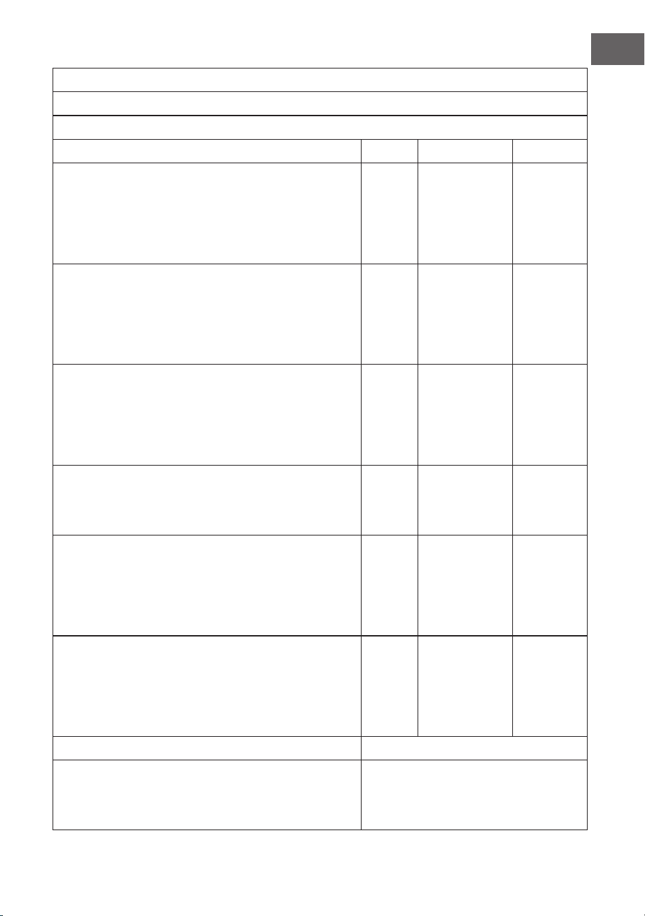
Product information requirements according to REGULATION (EU) No 206/2012
Information to identify the model(s) to which the information relates to
10048081, 10048082, 10048083, 10048084 - Klarstein Bolero Ceiling Fan
Description Symbol Value Unit
Maximum fan ow rate F Speed 1: 56.8
Speed 2: 85.2
Speed 3: 116.4
Speed 4: 139.8
Speed 5: 156.3
Speed 6: 170.6
m3/min
Fan power input P Speed 1: 4.5
Speed 2: 7.6
Speed 3: 12.5
Speed 4: 18.5
Speed 5: 25.1
Speed 6: 35.0
W
Service value SV Speed 1: 12.7
Speed 2: 11.3
Speed 3: 9.3
Speed 4: 7.5
Speed 5: 6.2
Speed 6: 4.9
(m3/min)/W
Standby power consumption with DC type LED lamp
Standby power consumption with AC type LED lamp
PSB 0.5
0.34
W
Fan sound power level LWA Speed 1: 33.6
Speed 2: 34.1
Speed 3: 36.6
Speed 4: 39.7
Speed 5: 43.2
Speed 6: 47.0
dB(A)
Maximum air velocity c Speed 1: 1.0
Speed 2: 1.5
Speed 3: 1.8
Speed 4: 2.2
Speed 5: 2.4
Speed 6: 2.8
m/s
Measurement standard for service value IEC 60879:2019
Contact details for obtaining more information Chal-Tec GmbH
Mühlenstraße 25
10243 Berlin
Deutschland


33
ES
DATOS TÉCNICOS
Número de artículo 10048081, 10048082, 10048083, 10048084
Alimentación 220-240 V~ 50/60 Hz
Potencia del ventilador 40 W
Caudal máximo 171 m
3
/min
Tipo de lámpara Portalámparas E27, máx.: 60 W
Datos técnicos 33
Indicaciones de seguridad 34
Partes suministradas 35
Instalación 36
Uso y funcionamiento 42
Indicaciones sobre la retirada del aparato 44
Fabricante 44
Estimado cliente:
Le felicitamos por la adquisición de este producto. Lea
atentamente el siguiente manual y siga cuidadosamente
las instrucciones de uso con el n de evitar posibles
daños. La empresa no se responsabiliza de los daños
ocasionados por un uso indebido del producto o por
haber desatendido las indicaciones de seguridad.
Escanee el código QR para acceder al manual de usuario
más reciente y a más información sobre el producto.
ÍNDICE

34
ES
INDICACIONES DE SEGURIDAD
• No je nunca el ventilador a una toma de corriente, sino al propio techo.
• La distancia mínima entre las aspas del ventilador y el suelo debe ser superior
a 2,3 m. La capacidad de carga mínima del gancho del que cuelga el ventilador
debe ser de 100 kg.
• Asegúrese de instalar un interruptor de desconexión de todos los polos con
una separación de contactos de al menos 3 mm entre polos en el cableado de
alimentación del ventilador de techo.
• El modelo o tipo de referencia de las luminarias que pueden instalarse en los
ventiladores construidos a tal efecto.
• Desconecte la alimentación antes de conectar.
• El cableado eléctrico debe ser conforme a la normativa local.
• El ventilador debe estar correctamente conectado a tierra para evitar el riesgo
de descargas eléctricas.
• Nunca monte el ventilador en una habitación húmeda o mojada.
• Tenga cuidado al trabajar cerca de las aspas giratorias.
• Los niños mayores de 8 años y las personas con discapacidad física, sensorial
o psíquica, o con falta de experiencia y conocimientos pueden utilizar el
aparato si han sido previamente instruidos por su tutor o supervisor sobre
el funcionamiento del mismo y conocen las funciones, las indicaciones de
seguridad y los riesgos asociados.
• Los niños no deben jugar con el aparato.
• Los niños no deben realizar tareas de limpieza y mantenimiento sin
supervisión.
• Asegúrese de que el ventilador esté desconectado de la red eléctrica antes de
retirar la protección.
• Tome precauciones para evitar el reujo de gases a la habitación desde la
chimenea abierta de aparatos de gas u otros combustibles (para ventiladores
de conductos y tabiques).
Nota: Encargue siempre la instalación de su ventilador a una persona con
conocimientos de cableado eléctrico.
35
ES
PARTES SUMINISTRADAS
Abra el embalaje con cuidado. Retire los artículos de los insertos de espuma de
poliestireno.
Retire la carcasa del motor y colóquela sobre una alfombra o espuma de
poliestireno para evitar daños en el acabado. Compruebe en el inventario de
piezas que se incluyen todas las piezas.
Marquesina
Soporte de techo
Cuchilla
mando a distancia
Varilla y bola de techo
Cubiertas decorativas
tornillos y tacos
Kit en espiral
pantalla de cristal
Barra de techo
Motor
36
ES
INSTALACIÓN
Preparación de la nstalación
Para evitar lesiones personales y
daños, asegúrese de que el lugar
de instalación permita que las
aspas tengan una distancia libre
de 2,3 m del suelo y de 76 cm de
cualquier pared u obstáculo.
Asegúrese de que la caja de
conexiones esté bien sujeta
a la estructura del edicio y
pueda soportar todo el peso del
ventilador.
Preparación del lugar de instalación del ventilador
Tubo de instalación
Este ventilador puede montarse en un techo normal o abovedado con una barra
de techo.
La longitud de suspensión puede aumentarse con una barra de techo más larga.
Para la instalación se necesitan las siguientes herramientas: destornillador,
destornillador de cabeza plana, alicates o llave inglesa ajustables, escalera de
mano, alicates cortacables y cinta aislante homologada.
20°
76 cm de la
pared o del
obstáculo
más cercano
2.3 m
cuchillas al suelo
Estilo de
montaje
estándar
El montaje estándar cuelga del techo
mediante una barra de techo
El montaje en ángulo está recomendado
para techos abovedados o en ángulo
Soporte de
apoyo
Soporte de
apoyo

37
ES
Instalación del soporte de techo
Taladre unoricio de ⌀8 mm en el techo de hormigón e inserte los tacos y los
pernos.
Alinee el soporte con el oricio y apriete la tuerca.
Techo de madera
Techo de hormigón
38
ES
Montar y colgar el ventilador
Cableado
eléctrico
Marquesina
pasador de tope
Cubiertas decorativas
Tornillo de jación del
yugo
adaptador
R clip
Ranura para
bola de techo
• Si desea ampliar la longitud de colgado de su ventilador, debe retirar la bola
de colgado de la varilla de bajada de 15 cm suministrada para utilizarla con
una varilla de bajada ampliada (incluida) . (Si desea utilizar la varilla de bajada
de 6 pulgadas, proceda con las instrucciones a continuación)
• Para retirar la bola de techo, aoje el tornillo de jación de la bola de techo y
retire el pasador y la abrazadera. Baje la bola de techo y retire el pasador de
tope. Deslice la bola de techo fuera de la varilla de techo original A y deslícela
por la varilla de techo más larga B (tenga en cuenta que la parte superior de
la varilla de techo tiene un oricio para el tornillo de ajuste; utilice este oricio
cuando ajuste el tornillo de ajuste).
• Inserte el pasador de bloqueo en la parte superior de la barra extensible y
levante la bola colgante.
• Asegúrese de que el pasador de tope se alinee con las ranuras del interior de
la bola de techo y apriete bien el tornillo de jación.
Consejo: Para preparar el paso de los cables eléctricos a través de la barra de
techo, aplique un pequeño trozo de cinta aislante a los extremos de los cables
eléctricos; esto mantendrá unidos los cables cuando se pasen a través de la barra
de techo.
• Aoje los tornillos de jación y la tuerca de la parte superior de la carcasa del
motor. Retire el pasador y el clip de la varilla (si aún no lo ha hecho). Deslice la
varilla a través de la cubierta.
• Tread electrical wires through downrod and pull extra wire slack from the
upper end of the downrod.
• Coloque la varilla de extensión en la horquilla de la carcasa del motor. Inserte
el pasador de tope y el clip que se retiraron anteriormente. Apriete los
tornillos de jación de la horquilla y la tuerca de forma segura. Baje la cubierta
hasta la carcasa del motor.

39
ES
Cubierta
Cableado
Montaje de la cubierta
ok
Levante la cubierta hasta el soporte para colgar, alineando los tornillos aojados
del soporte con los oricios ranurados de la cubierta. Gire la cubierta para
bloquearla. Vuelva a insertar los tornillos y fíjelos con un destornillador.
Con el soporte de suspensión jado a la caja de salida y capaz de soportar el
ventilador, ya está listo para colgar el ventilador. Sujete el ventilador rmemente
con las dos manos. Deslice la varilla de suspensión a través de la abertura del
soporte de suspensión y deje que la bola de suspensión descanse sobre el soporte
de suspensión. Gire la ranura de la bola de suspensión hasta que quede alineada
con la lengüeta del soporte de suspensión.
Nota: Pida ayuda a otra persona para que sujete la escalera y le levante el
ventilador una vez que se haya subido a ella.

40
ES
Conjunto de cuchillas
Montaje de la pantalla de lámpara
Ahorrar de tiempo: Las arandelas para los tornillos del aspa pueden colocarse en
cada tornillo antes de instalar las aspas.
Alinee los oricios de las cuchillas con los oricios de los tornillos del motor,
Apriete bien todos los tornillos una vez que todas las cuchillas estén jadas.
Repita la operación con el resto de los brazos de las cuchillas antes de jar
denitivamente los tornillos.
Nota: Apriete los tornillos de las aspas dos veces.
Tornillos
de las
aspas

41
ES
Montaje nalizado
Vuelva a colocar la cubierta y la pantalla de lámpara en el panel LED y fíjelas con
abrazaderas decorativas y tuercas para tornillos.

42
ES
USO Y FUNCIONAMIENTO
Mando a distancia
interruptor de la
lámpara
Sentido de giro
regulación de
la velocidad del
ventilador
temporizador
1 hora
2 horas
4 horas
8 horas
conversión de
lámparas
conversión de
lámparas

43
ES
R: Se utiliza el modo de correspondencia de códigos de aprendizaje entre el
emisor y el receptor. Encienda la fuente de alimentación en 30 segundos y pulse el
botón "FAN ON/OFF" del emisor durante 5 segundos. Puede cargar normalmente
después de escuchar un sonido largo de "abeja", lo que signica que el
aprendizaje ha tenido éxito y funciona normalmente.
Notas
• El modo de aprendizaje no se acepta después de conectar la alimentación
durante 30 segundos.
• Si el transmisor no puede controlar el receptor, compruebe que la pila
esté instalada correctamente o que el nivel de la pila sea demasiado bajo.
Compruebe si hay interferencias de productos electrónicos similares.

44
ES
INDICACIONES SOBRE LA RETIRADA DEL APARATO
Si en su país existe una disposición legal relativa a la
eliminación de aparatos eléctricos y electrónicos, este
símbolo estampado en el producto o en el embalaje
advierte que no debe eliminarse como residuo doméstico.
En lugar de ello, debe depositarse en un punto de
recogida de reciclaje de aparatos eléctricos y electrónicos.
Una gestión adecuada de estos residuos previene
consecuencias potencialmente negativas para el medio
ambiente y la salud de las personas. Puede consultar más
información sobre el reciclaje y la eliminación de este
producto contactando con su administración local o con
su servicio de recogida de residuos.
Este producto contiene baterías. Si en su país existe una
disposición legal relativa a la eliminación de baterías,
estas no deben eliminarse como residuo doméstico.
Infórmese sobre la normativa vigente relacionada con
la eliminación de baterías. Una gestión adecuada de
estos residuos previene consecuencias potencialmente
negativas para el medio ambiente y la salud de las
personas.
FABRICANTE
Chal-Tec GmbH, Mühlenstraße 25, 10243 Berlín, Alemania.
Contacto: [email protected]
45
ES
Requisitos de información del producto según REGLAMENTO (UE) nº 206/2012
Información para identicar el modelo o modelos a los que se reere la información
10048081, 10048082, 10048083, 10048084 - Ventilador de techo Bolero de Klarstein
Descripción Símbolo Valor Unidad
Caudal máximo del ventilador F Velocidad 1: 56,8
Velocidad 2: 85,2
Velocidad 3: 116,4
Velocidad 4: 139,8
Velocidad 5: 156,3
Velocidad 6: 170,6
m3/min
Entrada de alimentación para el ventilador P Velocidad 1: 4,5
Velocidad 2: 7,6
Velocidad 3: 12,5
Velocidad 4: 18,5
Velocidad 5: 25,1
Velocidad 6: 35,0
W
Valor del servicio SV Velocidad 1: 12,7
Velocidad 2: 11,3
Velocidad 3: 9,3
Velocidad 4: 7,5
Velocidad 5: 6,2
Velocidad 6: 4,9
(m3/min)/W
Consumo de energía en modo de espera con
lámpara LED de tipo CC
Consumo de energía en modo de espera con
lámpara LED de tipo CC
RSP 0,5
0.34
W
Nivel de potencia acústica del ventilador LWA Velocidad 1: 33,6
Velocidad 2: 34,1
Velocidad 3: 36,6
Velocidad 4: 39,7
Velocidad 5: 43,2
Velocidad 6: 47,0
dB(A)
Velocidad máxima del aire c Velocidad 1: 1,0
Velocidad 2: 1,5
Velocidad 3: 1,8
Velocidad 4: 2,2
Velocidad 5: 2,4
Velocidad 6: 2,8
m/s
Norma de medición del valor del servicio IEC 60879:2019
Datos de contacto para obtener más información Chal-Tec GmbH,
Mühlenstrasse 25,
10243 Berlín, Alemania.


47
FR
FICHE TECHNIQUE
Numéro d'article 10048081, 10048082, 10048083, 10048084
Alimentation électrique 220-240 V~ 50/60 Hz
Puissance du ventilateur 40 W
Débit maximal 171 m
3
/min
Type de lampe Douille E27, max. : 60 W
Fiche technique 47
Consignes de sécurité 48
Contenu de la livraison 49
Installation 50
Fonctionnement et utilisation 56
Informations sur le recyclage 58
Fabricant 58
Chère cliente, cher client,
Félicitation pour acquisition de ce nouvel appareil.
Veuillez lire attentivement ce manuel et tenir compte des
conseils suivants concernant l'installation et l'utilisation
an d'éviter tout dommage technique. Nous déclinons
toute responsabilité pour les dommages causés par
le non-respect des instructions et une utilisation
inappropriée. Scannez le code QR pour accéder au
dernier manuel d'utilisation et à d'autres informations
sur le produit.
SOMMAIRE

48
FR
CONSIGNES DE SÉCURITÉ
• Ne jamais xer le ventilateur à une prise de courant, mais au plafond lui-
même.
• La distance minimale entre les pales du ventilateur et le sol doit être
supérieure à 2,3 m. La capacité de charge minimale du crochet auquel le
ventilateur est suspendu doit être de 100 kg.
• Veillez à installer un interrupteur de déconnexion à tous les pôles avec une
séparation de contact d'au moins 3 mm entre les pôles dans le câblage
d'alimentation du ventilateur de plafond.
• La référence du modèle ou du type de luminaires qui peuvent être installés
dans les ventilateurs construits à cet effet.
• Couper l'alimentation avant de procéder à la connexion.
• Le câblage électrique doit être conforme à la réglementation locale.
• Le ventilateur doit être correctement mis à la terre pour éviter tout risque de
choc électrique.
• Ne jamais installer le ventilateur dans une pièce humide ou mouillée.
• Soyez prudent lorsque vous travaillez à proximité des pales du rotor.
• Cet appareil ne peut être utilisé que par des enfants âgés de 8 ans ou plus
et des personnes dont les capacités physiques, sensorielles et mentales sont
limitées et/ou dénuées d'expérience et de connaissances, à condition qu'elles
aient été initiées à l'utilisation de l'appareil par une personne responsable qui
comprend les risques associés.
• Les enfants ne doivent pas jouer avec l’appareil.
• Le nettoyage et l’entretien ne doivent pas être effectués par des enfants sans
surveillance.
• Assurez-vous que le ventilateur est hors tension avant de retirer la protection.
• Prendre des précautions pour éviter le reux de gaz dans la pièce à partir du
conduit ouvert d'un appareil à gaz ou d'un autre appareil à combustible (pour
les ventilateurs de gaine et de cloison).
Remarque : Faites toujours installer votre ventilateur par quelqu'un qui s'y
connaît en matière de câblage électrique.
49
FR
CONTENU DE LA LIVRAISON
Ouvrez soigneusement l'emballage. Retirer les articles des inserts en polystyrène.
Retirer le boîtier du moteur et le placer sur un tapis ou de la mousse de
polystyrène pour éviter de l'endommager. Retirez le boîtier du moteur et placez-le
sur un tapis ou du polystyrène pour éviter d'endommager la nition. Vérier dans
l'inventaire des pièces que toutes les pièces sont bien présentes.
Abat-jour
Support de suspension
Pale
Télécommande
Tige et boule de suspension
Caches décoratifs
vis et chevilles
Paquet en spirale
abat-jour en verre
Tige de suspension
Moteur
50
FR
INSTALLATION
Préparation de l'installation
Pour éviter les blessures et les
dommages, veillez à ce que
l'emplacement de suspension
permette aux pales d'être à 2,3 m
du sol et à 76 cm d'un mur ou d'un
obstacle.
Assurez-vous que le boîtier de
sortie est solidement xé à la
structure du bâtiment et peut
supporter le poids total du
ventilateur.
Préparation de l'emplacement du ventilateur
Installation des tiges de suspension
Ce ventilateur peut être monté sur un plafond normal ou voûté à l'aide d'une tige
de suspension.
La longueur de suspension peut être augmentée en utilisant une tige plus longue.
Tournevis, tournevis plat, pince ou clé à molette, escabeau, pince coupante et
ruban adhésif.
20°
76 cm du
mur ou de
l'obstacle le
plus proche
2,3 m
des pales au sol
Montage
type
standard
Le montage standard est xé au
plafond par une tige de suspension
Montage en angle recommandé pour
un plafond voûté ou en angle
Support de
soutien
Support de
soutien
51
FR
Installation du support de suspension
Percez un trou de ⌀8 mm sur le plafond en béton et insérez les chevilles et les
boulons.
Alignez le support avec le trou et serrez l'écrou.
Plafond en bois
Plafond en béton
52
FR
Assemblage et suspension du ventilateur
câblage électrique
Abat-jour
goupille d'arrêt
Caches décoratifs
vis de réglage de
support
adaptateur
R clip
fente d'accrochage
de la boule
Si vous souhaitez allonger la longueur de suspension de votre ventilateur, vous
devez retirer la boule de suspension de la tige de descente de 6 pouces fournie
pour l'utiliser avec une tige de descente rallongée (incluse). (Si vous souhaitez
utiliser la tige de suspension de 6 pouces, veuillez suivre les instructions ci-
dessous)
Pour retirer la boule de suspension, desserrez la vis de réglage de la boule et
retirez la goupille et le clip. Abaissez la boule de suspension et retirez la goupille
d'arrêt. Faites glisser la boule hors de la tige de suspension d'origine A et faites-
la glisser le long de la tige de suspension plus longue B (notez que la partie
supérieure de la tige de suspension comporte un trou de vis de réglage ; utilisez ce
trou pour régler la vis de réglage).
Insérer la goupille d'arrêt dans la partie supérieure de la tige de suspension
rallongée et soulever la boule de suspension.
Veillez à ce que la goupille d'arrêt s'aligne sur les fentes situées à l'intérieur de la
boule de suspension et serrez fermement la vis de réglage.
Remarque : Pour préparer l'enlage des ls électriques à travers la tige de
suspension, appliquez un petit morceau de ruban électrique aux extrémités des
ls électriques - cela maintiendra les ls ensemble lors de leur enlage à travers la
tige de suspension.
Desserrez les vis de réglage et l'écrou de la culasse en haut du boîtier du moteur.
Retirer la goupille et le clip de la tige de suspension (si ce n'est pas déjà fait). Faites
glisser la tige à travers l'abat-jour.
Faites passer les ls électriques à travers la tige de suspension et tirez le l
supplémentaire de l'extrémité supérieure de la tige de suspension.
Placer la tige de suspension dans l'étrier du carter du moteur. Insérer la goupille
d'arrêt et le clip retirés précédemment. Serrez fermement les vis de réglage et
l’écrou de l’étrier. Abaisser l'abat-jour sur le boîtier du moteur.
53
FR
Abat-jour
câblage
Assemblage de l'abat-jour
ok
Soulever l'abat-jour jusqu'au support de suspension, en alignant les vis desserrées
dans le support de suspension avec des trous oblongs dans l'abat-jour. Tourner
l'abat-jour pour le verrouiller. Remettez les vis et serrez-les toutes à l'aide d'un
tournevis.
Une fois le support de suspension xé à la boîte de sortie et capable de supporter
le ventilateur, vous êtes maintenant prêt à accrocher votre ventilateur. Saisir
fermement le ventilateur à deux mains. Faites glisser la tige de suspension par
l'ouverture du support et faites reposer la boule sur le support de suspension.
Tournez la fente de la boule de suspension jusqu'à ce qu'elle s'aligne avec la
languette du support de suspension.
Conseil: demandez l'aide d'une autre personne pour tenir l'escabeau en place
et pour soulever le ventilateur à votre hauteur une fois que vous êtes installé
sur l'échelle.
54
FR
Assemblage des pales
Assemblage de l'abat-jour
Gain de temps : Placez les rondelles sur chaque vis de pale avant d'installer la pale.
Alignez les trous des pales avec les trous des vis du moteur, et serrez toutes les vis
une fois que toutes les pales sont xées. Répétez l'opération avec les autres bras
de pale avant de serrer dénitivement les vis.
Remarque : serrer les vis de la pale deux fois.
Vis du bras
de pale

55
FR
Assemblage terminé
Remettez le couvercle et l'abat-jour en place sur le panneau LED et xez-les à
l'aide de clips décoratifs et de boulons.
56
FR
FONCTIONNEMENT ET UTILISATION
Contrôle à distance
interrupteur de lampe
sens de rotation
régulation de la
vitesse du ventilateur
Minuterie
1 heure
2 heures
4 heures
8 heures
conversion des
lampes
conversion des
lampes

57
FR
A : Le mode de correspondance des codes d'apprentissage est utilisé entre
l'émetteur et le récepteur. Mettez l'alimentation électrique sous tension dans
les 30 secondes et appuyez sur le bouton FAN ON/OFF de l'émetteur pendant 5
secondes. Il se charge normalement après avoir émis un long son bip qui signie
que l'apprentissage est terminé et qu'il fonctionne normalement.
Remarques
• Le mode d'apprentissage n'est pas accepté après une mise sous tension de 30
secondes.
• Si l'émetteur ne peut pas contrôler le récepteur, vériez que la pile est
correctement installée et qu'elle n'est pas trop faible. Vérier qu'il n'y a pas
d'interférences avec des produits électroniques similaires.

58
FR
INFORMATIONS SUR LE RECYCLAGE
S‘il existe une réglementation pour l‘élimination ou le
recyclage des appareils électriques et électroniques dans
votre pays, ce symbole sur le produit ou sur l‘emballage
indique que cet appareil ne doit pas être jeté avec les
ordures ménagères. Vous devez le déposer dans un point
de collecte pour le recyclage des équipements électriques
et électroniques. La mise au rebut conforme aux règles
protège l‘environnement et la santé de vos semblables
des conséquences négatives. Pour plus d‘informations
sur le recyclage et l‘élimination de ce produit, veuillez
contacter votre autorité locale ou votre service de
recyclage des déchets ménagers.
Ce produit contient des piles. S‘il existe une
réglementation pour l‘élimination ou le recyclage des
piles dans votre pays, vous ne devez pas les jeter avec les
ordures ménagères. Renseignez-vous sur les dispositions
locales relatives à la collecte des piles usagées. La mise au
rebut conforme aux règles protège l‘environnement et la
santé de vos semblables des conséquences négatives.
FABRICANT
Chal-Tec GmbH, Mühlenstraße 25, 10243 Berlin, Allemagne.
Contact : [email protected]
59
FR
Exigences en matière d'informations sur les produits conformément à RÈGLEMENT (UE) No
206/2012
Informations permettant d'identier le(s) modèle(s) auquel (auxquels) les informations se rapportent
10048081, 10048082, 10048083, 10048084 - Ventilateur de plafond Klarstein Bolero
Description Symbole Valeur Appareil
Débit maximal du ventilateur F Vitesse 1 : 56,8
Vitesse 2 : 85,2
Vitesse 3 : 116,4
Vitesse 4 : 139,8
Vitesse 5 : 156,3
Vitesse 6 : 170,6
m3/min
alimentation du ventilateur P Vitesse 1 : 4,5
Vitesse 2 : 7,6
Vitesse 3 : 12,5
Vitesse 4 : 18,5
Vitesse 5 : 25,1
Vitesse 6 : 35,0
W
Valeur correspondante SV Vitesse 1 : 12,7
Vitesse 2 : 11,3
Vitesse 3 : 9,3
Vitesse 4 : 7,5
Vitesse 5 : 6,2
Vitesse 6 : 4,9
(m3/min)/W
Consommation en veille avec une lampe LED de type CC
Consommation en veille avec une lampe LED de type CA
PSB 0,5
0,34
W
Niveau de puissance acoustique du ventilateur LWA Vitesse 1 : 33,6
Vitesse 2 : 34,1
Vitesse 3 : 36,6
Vitesse 4 : 39,7
Vitesse 5 : 43,2
Vitesse 6 : 47,0
dB(A)
Vitesse maximale de l'air c Vitesse 1 : 1,0
Vitesse 2 : 1,5
Vitesse 3 : 1,8
Vitesse 4 : 2,2
Vitesse 5 : 2,4
Vitesse 6 : 2,8
m/s
Norme de mesure de la valeur des services IEC 60879:2019
Coordonnées pour obtenir plus d'informations Chal-Tec GmbH,
Mühlenstrasse 25,
10243 Berlin,
Allemagne.


61
IT
DATI TECNICI
Numero articolo 10048081, 10048082, 10048083, 10048084
Alimentazione 220-240 V~ 50/60 Hz
Potenza del ventilatore 40 W
Flusso massimo 171 m
3
/min
Tipo di lampadina Portalampada E27, max: 60 W
Dati tecnici 61
Avvertenze di sicurezza 62
Volume di consegna 63
Installazione 64
Utilizzo 70
Avviso di smaltimento 72
Produttore 72
Gentile cliente,
grazie per aver acquistato questo dispositivo. Leggere
attentamente il presente manuale e rispettare le
indicazioni seguenti relative a installazione e utilizzo per
evitare danni tecnici. Malfunzionamenti causati dalla
mancata osservanza delle indicazioni e delle avvertenze
su installazione e utilizzo contenute nel manuale non
sono coperti dalla garanzia. Scansionare il codice QR
per accedere al manuale d'uso più recente e a maggiori
informazioni sul prodotto.
INDICE

62
IT
AVVERTENZE DI SICUREZZA
• Non ssare mai il ventilatore a una presa di corrente, ma al sotto stesso.
• La distanza minima tra le pale del ventilatore e il pavimento deve essere
superiore a 2,3 metri. La portata minima del gancio a cui è appeso il
ventilatore deve essere di 100 kg.
• Assicurarsi di installare nel cablaggio di alimentazione del ventilatore a sotto
un sezionatore onnipolare con una separazione dei contatti di almeno 3 mm
tra i poli.
• Il modello o la tipologia di riferimento delle lampade che possono essere
installate nei ventilatori costruiti per questo scopo.
• Spegnere l'alimentazione prima di effettuare il collegamento.
• Il cablaggio elettrico deve essere conforme alla normativa locale.
• Il ventilatore deve essere adeguatamente messo a terra per evitare il rischio di
scosse elettriche.
• Non montare mai il ventilatore in un ambiente umido o bagnato.
• Prestare attenzione quando si lavora vicino alle pale.
• Questo dispositivo può essere utilizzato solo da bambini di età pari o
superiore a 8 anni e da persone con capacità siche, sensoriali e mentali
limitate e/o prive di esperienza e conoscenza, a condizione che siano stati
istruiti all'uso del dispositivo da una persona responsabile che comprenda i
rischi associati.
• I bambini non devono giocare con l’apparecchio.
• La pulizia e la manutenzione non devono essere effettuate dai bambini senza
supervisione.
• Prima di rimuovere la protezione, assicurarsi che il ventilatore sia scollegato
dalla rete di alimentazione.
• Prendere le precauzioni necessarie per evitare il riusso di gas nel locale dalla
canna fumaria aperta di dispositivi a gas o di altri combustibili (per i ventilatori
a condotto e divisori).
Nota: il ventilatore deve essere installato da una persona esperta di cablaggio
elettrico.

63
IT
VOLUME DI CONSEGNA
Aprire con attenzione la confezione. Rimuovere gli articoli dagli inserti di
polistirolo.
Rimuovere l'alloggiamento del motore e posizionarlo su un tappeto o sul
polistirolo per evitare di danneggiare la nitura. Vericare con la lista dei
componenti che tutti i pezzi siano inclusi.
copertura
staffa di sospensione
pala
telecomando
asta e sfera di sospensione
coperture decorative
viti e tasselli
pacchetto a spirale
paralume in vetro
asta
motore

64
IT
INSTALLAZIONE
Preparazione all'installazione
Per evitare lesioni e danni alle
persone, assicurarsi che la
posizione di ssaggio consenta
alle pale di trovarsi a 2,3 m dal
pavimento e a 76 cm da qualsiasi
parete o ostacolo.
Assicurarsi che la scatola di
montaggio sia ssata saldamente
alla struttura dell'edicio e
possa sostenere l'intero peso del
ventilatore.
Preparazione del luogo di posizionamento per il ventilatore
Installazione dell'asta di sostegno
Questo ventilatore può essere montato su un sotto normale o a volta utilizzando
un'asta di sostegno.
La distanza dal sotto può essere incrementata utilizzando un'asta più lunga.
Per l'installazione sono necessari questi attrezzi: cacciavite, cacciavite a testa
piatta, pinze o chiavi regolabili, scaletta, tronchesi e nastro isolante conforme alle
speciche.
76 cm dalla
parete
o dagli
ostacoli più
vicini
2,3 m
dalle pale al
pavimento
20°
stile di
montaggio
standard
Il montaggio standard prevede la
sospensione dal sotto tramite
un'asta
Il montaggio inclinato è consigliato
per sotti a volta o a spiovente.
sostegno
sostegno

65
IT
Installazione della staffa di sospensione
Praticare un foro di ⌀8 mm sul sotto in calcestruzzo e inserire i tasselli e le viti.
Allineare la staffa al foro e serrare con il dado.
sotto in legno
sotto in
calcestruzzo

66
IT
Montaggio e ssaggio del ventilatore
cablaggio elettrico
copertura
perno di arresto
coperture decorative
Vite di ssaggio
della staffa a U
Adattatore
clip R
fessura per la sfera
di sospensione
Se si desidera estendere la lunghezza di sospensione del ventilatore, è necessario
rimuovere la sfera di sospensione dall'asta da 6 pollici in dotazione per utilizzarla
con un'asta più lunga (inclusa). (Se si desidera utilizzare l'asta da 6 pollici,
procedere con le istruzioni riportate di seguito).
Per rimuovere la sfera di sospensione, allentare la vite di fermo sulla sfera e
rimuovere il perno e la clip. Abbassare la sfera di sospensione e rimuovere il perno
di arresto. Far scorrere la sfera di sospensione dall'asta originale A sull'asta più
lunga B (notare che la parte superiore dell'asta è dotata di un foro per la vite di
fermo; utilizzare questo foro per regolare la vite di fermo).
Inserire il perno di arresto nella parte superiore dell'asta più lunga e sollevare la
sfera di sospensione.
Assicurarsi che il perno di arresto sia allineato con le fessure all'interno della sfera
di sospensione e serrare saldamente la vite di fermo.
Consiglio: per prepararsi a far passare i li elettrici nell'asta, applicare un piccolo
pezzo di nastro isolante alle estremità dei li elettrici, in modo da tenerli uniti
quando vengono inlati nell'asta.
Allentare le viti di fermo e il dado nella parte superiore dell'alloggiamento del
motore. Rimuovere il perno e la clip dall'asta (se non lo si è già fatto). Far passare
l'asta attraverso la copertura.
Far passare i cavi elettrici attraverso l'asta e tirare il lo in eccesso
dall'estremità superiore dell'asta.
Inserire l'asta nella staffa a U dell'alloggiamento del motore. Inserire il perno di
arresto e la clip precedentemente rimossi. Serrare saldamente le viti di fermo della
staffa a U e il dado. Abbassare la copertura sull'alloggiamento del motore.

67
IT
copertura
Cablaggio
Montaggio della copertura
ok
Sollevare la copertura sulla staffa di sospensione, allineando le viti allentate nella
staffa di sospensione con i fori nella copertura. Ruotare la copertura per ssarla.
Reinserire le viti e stringerle tutte con un cacciavite.
Con la staffa di sospensione ssata alla scatola di montaggio e in grado di
sostenere il ventilatore, ora è possibile agganciare il ventilatore. Afferrare
saldamente il ventilatore con due mani. Far passare l'asta attraverso l'apertura
della staffa di sospensione e lasciare che la sfera di sospensione poggi sulla
staffa di sospensione. Ruotare la fessura della sfera di sospensione no a farla
coincidere con la linguetta della staffa di sospensione.
Consiglio: chiedere l'aiuto di un'altra persona per tenere la scaletta in posizione
e per sollevare il ventilatore una volta che ci si trova sulla scala.

68
IT
Montaggio delle pale
Montaggio del paralume
Risparmio di tempo: le rondelle per le viti della pala possono essere posizionate su
ogni vite della pala prima dell'installazione della stessa.
Allineare i fori delle pale con i fori delle viti del motore, stringere le viti una volta
ssate tutte le pale. Prima di ssare denitivamente le viti, ripetere l'operazione
con gli altri bracci delle pale.
Nota: serrare due volte le viti del braccio della pala.
viti dei
bracci delle
pale

69
IT
Montaggio concluso
Riposizionare la copertura e il paralume sul pannello LED e ssarli con le clip
decorative e i dadi.

70
IT
UTILIZZO
Telecomando
interruttore della
lampada
Direzione di
rotazione
regolazione della
velocità del ventilatore
timer
1 ora
2 ore
4 ore
8 ore
conversione della
lampada
conversione della
lampada

71
IT
A: la modalità di apprendimento per l’abbinamento dei codici viene utilizzata tra
il trasmettitore e il ricevitore. Attivare l'alimentazione entro 30 secondi e premere
il tasto "FAN ON/OFF" del trasmettitore per 5 secondi. Può caricarsi normalmente
dopo un lungo segnale acustico, a indicare che l'apprendimento è riuscito e che
funziona normalmente.
Note
• La modalità di apprendimento non viene accettata dopo aver attivato
l'alimentazione per 30 secondi.
• Se il trasmettitore non riesce a controllare il ricevitore, vericare che la
batteria sia installata correttamente o se il livello della batteria è troppo basso.
Vericare l'assenza di interferenze da parte di prodotti elettronici simili.
72
IT
AVVISO DI SMALTIMENTO
Se nel proprio paese si applicano le regolamentazioni
inerenti lo smaltimento di dispositivi elettrici ed
elettronici, questo simbolo sul prodotto o sulla confezione
segnala che questi prodotti non possono essere
smaltiti con i riuti normali e devono essere portati a
un punto di raccolta di dispositivi elettrici ed elettronici.
Grazie al corretto smaltimento dei vecchi dispositivi si
tutela il pianeta e la salute delle persone da possibili
conseguenze negative. Informazioni riguardanti il riciclo
e lo smaltimento di questi prodotti si ottengono presso
l’amministrazione locale oppure il servizio di gestione dei
riuti domestici.
Il prodotto contiene batterie. Se nel proprio paese si
applicano le regolamentazioni inerenti lo smaltimento
di batterie, non possono essere smaltite con i normali
riuti domestici. Preghiamo di informarvi sulle
regolamentazioni vigenti sullo smaltimento delle
batterie. Grazie al corretto smaltimento dei vecchi
dispositivi si tutela l’ambiente e la salute delle persone da
conseguenze negative.
PRODUTTORE
Chal-Tec GmbH, Mühlenstraße 25, 10243 Berlino, Germania.
Contatto: [email protected]
73
IT
Requisiti relativi alle informazioni sul prodotto secondo REGOLAMENTO (UE) N. 206/2012
Informazioni per identicare il modello o i modelli a cui si riferiscono le informazioni
10048081, 10048082, 10048083, 10048084 - Klarstein Bolero Ventilatore a sotto
Descrizione Simbolo Valore Unità
Flusso massimo del ventilatore F Velocità 1: 56,8
Velocità 2: 85,2
Velocità 3: 116,4
Velocità 4: 139,8
Velocità 5: 156,3
Velocità 6: 170,6
m3/min
Potenza in inngresso del ventilatore P Velocità 1: 4,5
Velocità 2: 7,6
Velocità 3: 12,5
Velocità 4: 18,5
Velocità 5: 25,1
Velocità 6: 35,0
W
Valore di servizio SV Velocità 1: 12,7
Velocità 2: 11,3
Velocità 3: 9,3
Velocità 4: 7,5
Velocità 5: 6,2
Velocità 6: 4,9
(m3/min)/W
Consumo di energia in standby con lampada LED di tipo
CC
Consumo di energia in standby con lampada LED di tipo
CA
PSB 0,5
0,34
W
Rumorosità operativa del ventilatore LWA Velocità 1: 33,6
Velocità 2: 34,1
Velocità 3: 36,6
Velocità 4: 39,7
Velocità 5: 43,2
Velocità 6: 47,0
dB(A)
Velocità massima dell'aria c Velocità 1: 1,0
Velocità 2: 1,5
Velocità 3: 1,8
Velocità 4: 2,2
Velocità 5: 2,4
Velocità 6: 2,8
m/s
Standard di misurazione del valore di servizio IEC 60879:2019
Contatti per ottenere maggiori informazioni Chal-Tec GmbH
Mühlenstraße 25
10243 Berlino
Germania


www.klarstein.com