Loading ...
Loading ...
Loading ...
Part number 550-100-260/0520
109
ECO
®
Tec
GAS-FIRED WATER BOILER – 80/110/150/199 BOILER MANUAL
Annual startup (continued)
Check ignition wiring
1. Check ignition cable electrical resistance. A good cable will
have resistance between 950 and 1050 ohms. Replace if not
acceptable.
2. Inspect boiler ground wire from heat exchanger access cover
to ground terminal screw.
3. Verify all wiring is in good condition and securely attached.
4. Check ground continuity of wiring using continuity meter.
5. Replace ground wires if results are not satisfactory.
Check all boiler wiring
1. Inspect all boiler wiring, making sure wires are in good
condition and securely attached.
2. Verify that all connectors are securely inserted.
Check control settings
1. Use the control display to navigate through all settings.
Adjust settings if necessary.
2. Check settings of external limit controls (if any) and adjust
if necessary. Adjust as needed to accommodate the system
design.
Perform startup and checks
1. Start boiler and perform checks and tests specified in this
manual, including combustion performance check starting
on page 100.
2. Verify cold fill pressure is correct and that operating pressure
does not go too high. Adjust water pressure and expansion
tank charge pressure as necessary.
3. Complete the check-out procedure on page 104.
Check low water cutoff
Check the Low Water Cutoff for proper operation. Refer to
manufacturer’s instructions for operation and service.
Check burner flame
The boiler contains ceramic fiber materials.
Use care when handling these materials per
instructions on page 106 of this manual. Failure
to comply could result in severe personal injury.
1. Inspect flame through observation window using the
procedure on page 100.
2. If flame is unsatisfactory at either high fire or low fire, check
combustion values. If combustion is properly adjusted,
turn off boiler and allow boiler to cool down. Then remove
burner and clean it thoroughly using a vacuum cleaner or
compressed air. Do not use compressed air to clean burner
if performed inside a building.
3. To access the burner, remove the heat exchanger cover plate
following the procedure beginning on page 128.
4. If replacing the burner, ensure the burner gasket is in good
condition and correctly positioned. Follow all instructions
on page 128 or 130 to reinstall all components.
5. Restart the boiler.
6. Inspect the flame at high and low fire. If flame is still not
acceptable, check combustion values. If combustion is
properly adjusted, obtain a replacement burner from
Weil-McLain.
Check flame signal
1. Navigate to Diagnostics/Inputs on the control display
(see Figure 80, page 87 for navigation instructions and
Figure 88, page 94 for the complete Diagnostics menus).
2. e ame signal value (in micro amps) must be at least the
boost value listed in Figure97. If the ame signal drops below
this level, the control will attempt to correct by increasing the
blower speed to increase ame signal. At ignition, the proof of
ame signal must be 0.8 or greater. Typical running ame signal
should be between 4 and 6. is value will vary depending on
blower modulation, gas type, combustion settings, altitude &
age of components.
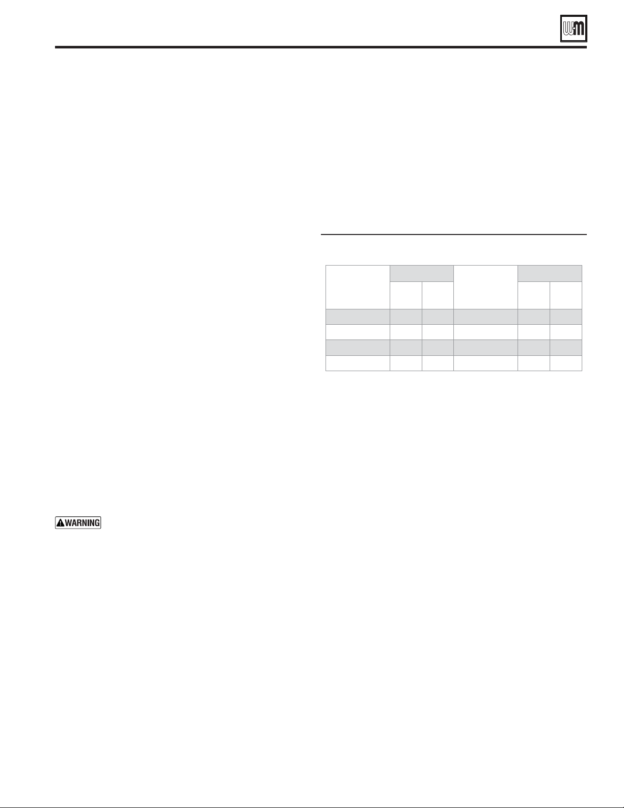
Running flame signal shutdown and boost
values
80 NG 1.5 2.0 150 NG 1.5 2.5
80 LP 1.5 2.5 150 LP 1.5 2.5
110 NG 1.5 2.0 199 NG 1.5 2.0
110 LP 1.5 2.5 199 LP 1.5 2.5
3. A low flame signal may indicate a fouled ignition electrode or
damaged ignition electrode insulation.
a. See Inspect ignition electrode, page 108 to remove and
inspect the ignition electrode .
b. If required, clean the ignition electrode as instructed.
c. If cleaning the ignition electrode does not improve, ground
wiring is in good condition, and ground continuity is
satisfactory, replace the ignition electrode .
4. If flame signal still remains low:
a. Inspect the vent and air piping.
b. Check combustion values.
c. Then inspect the heat exchanger, following the procedures
given in this manual for removal and reinstallation of the
heat exchanger cover plate and other boiler components
(see page 128).
d. Clean the exchanger as described in this manual if necessary.
Check blower speeds
1. For all installations make sure the correct altitude is set in the
boiler setup menu. The control automatically adjusts low fire,
ignition and high fire rates to compensate for high altitude
conditions.
2. Use the control display to navigate to DIAGNOSTICS/Manual
test mode (see Figure 80, page 87 for navigation instructions
and Figure 88, page 94 for the complete Diagnostics menus).
3. Set the firing rate to LOW (low fire).
4. Write down the blower RPM value, it should be within 50
of the value given in Figure 98, page 110 for Natural gas,
Figure 99, page 111 for LP propane gas, unless low fire speed
was increased based on priority need.
5. Set the firing rate to IGNITION (ignition rate).
6. Write down the blower RPM value. It should be within 50
RPM of the value listed in Figure 98, page 110 for Natural gas,
Figure 99, page 111 for LP propane gas,.
7. Set the firing rate to HIGH (high fire).
Loading ...
Loading ...
Loading ...