Loading ...
Loading ...
Loading ...
ADJUST PILOT BURNER
Pilot flame should surround 3/8' to 1/2" of the pilot sensor.
Refer to Fig. 19. If flame needs adjusting, do it as follows:
1. Remove screw cover over pilot adjusting screw.
2. Insert small screwdriver and adjust flame as needed. Turn
screw counterclockwise to increase flame, clockwise to
decrease.
3. Replace screw cover over pilot adjusting screw.
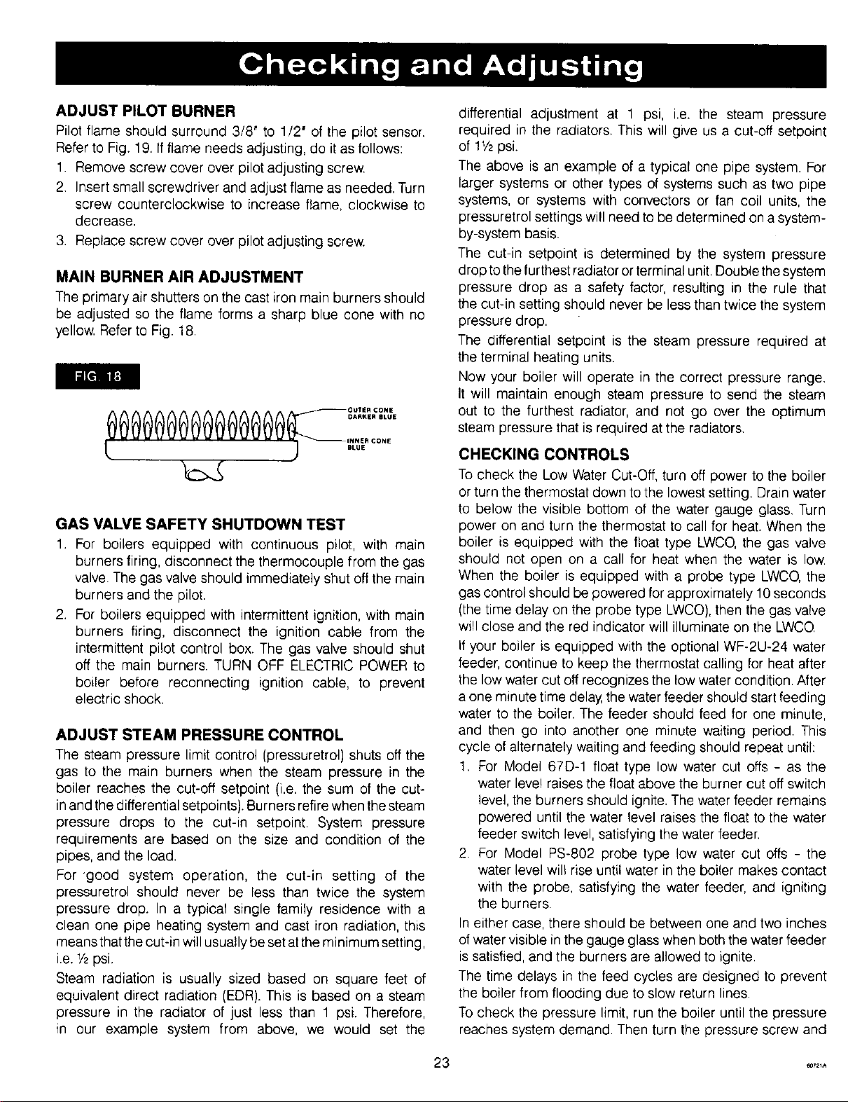
MAIN BURNER AIR ADJUSTMENT
The primary air shutters on the cast iron main burners should
be adjusted so the flame forms a sharp blue cone with no
yellow. Refer to Fig. 18.
li_[_ll i1I:]
0000@@0@0000 °°'''°°''
I_ARKIER BLUE
INNER CONE
t ) .Lo.
GAS VALVE SAFETY SHUTDOWN TEST
1. For boilers equipped with continuous pilot, with main
burners firing, disconnect the thermocouple from the gas
valve. The gas valve should immediately shut off the main
burners and the pilot.
2. For boilers equipped with intermittent ignition, with main
burners firing, disconnect the ignition cable from the
intermittent pilot control box. The gas valve should shut
off the main burners. TURN OFF ELECTRIC POWER to
boiler before reconnecting ignition cable, to prevent
electric shock.
ADJUST STEAM PRESSURE CONTROL
The steam pressure limit control (pressuretrol) shuts off the
gas to the main burners when the steam pressure in the
boiler reaches the cut-off setpoint (i.e. the sum of the cut-
in and the differential setpoints). Burners retire when the steam
pressure drops to the cut-in setpoint. System pressure
requirements are based on the size and condition of the
pipes, and the load.
For 'good system operation, the cut-in setting of the
pressuretrol should never be less than twice the system
pressure drop. In a typical single family residence with a
clean one pipe heating system and cast iron radiation, this
means that the cut-in will usually be set atthe minimum setting,
i.e. 1/2psi.
Steam radiation is usually sized based on square feet of
equivalent direct radiation (EDR). This is based on a steam
pressure in the radiator of just less than 1 psi. Therefore,
in our example system from above, we would set the
differential adjustment at 1 psi, i.e. the steam pressure
required in the radiators. This will give us a cut-off setpoint
of 11/2psi.
The above is an example of a typical one pipe system. For
larger systems or other types of systems such as two pipe
systems, or systems with convectors or fan coil units, the
pressuretrol settings will need to be determined on a system-
by-system basis.
The cut-in setpoint is determined by the system pressure
drop tothe furthest radiator or terminal unit. Double the system
pressure drop as a safety factor, resulting in the rule that
the cut-in setting should never be less than twice the system
pressure drop.
The differential setpoint is the steam pressure required at
the terminal heating units.
Now your boiler will operate in the correct pressure range.
It will maintain enough steam pressure to send the steam
out to the furthest radiator, and not go over the optimum
steam pressure that is required at the radiators.
CHECKING CONTROLS
To check the Low Water Cut-Off, turn off power to the boiler
or turn the thermostat down to the lowest setting. Drain water
to below the visible bottom of the water gauge glass. Turn
power on and turn the thermostat to call for heat. When the
boiler is equipped with the float type LWCO, the gas valve
should not open on a call for heat when the water is low.
When the boiler is equipped with a probe type LWCO, the
gas control should be powered for approximately 10 seconds
(the time delay on the probe type LWCO), then the gas valve
will close and the red indicator will illuminate on the LWCQ
If your boiler is equipped with the optional WF-2U-24 water
feeder, continue to keep the thermostat calling for heat after
the low water cut off recognizes the low water condition. After
a one minute time delay, the water feeder should start feeding
water to the boiler, The feeder should feed for one minute,
and then go into another one minute waiting period. This
cycle of alternately waiting and feeding should repeat until:
1. For Model 67D-1 float type low water cut offs - as the
water leve! raises the float above the burner cut off switch
level, the burners should ignite. The water feeder remains
powered until the water level raises the float to the water
feeder switch level, satisfying the water feeder,
2. For Model PS-802 probe type tow water cut offs - the
water level wil! rise until water in the boiler makes contact
with the probe, satisfying the water feeder, and igniting
the burners
In either case, there should be between one and two inches
of water visible in the gauge glass when both the water feeder
is satisfied, and the burners are allowed to ignite.
The time delays in the feed cycles are designed to prevent
the boiler from flooding due to slow return lines.
To check the pressure limit, run the boiler until the pressure
reaches system demand. Then turn the pressure screw and
3 _21A
Loading ...
Loading ...
Loading ...