Loading ...
Loading ...
Loading ...
probetypelowwatercutotis,thismayoccureachtimethe
lowwatercutoffdetectsa lowwaterconditionIfthisisthe
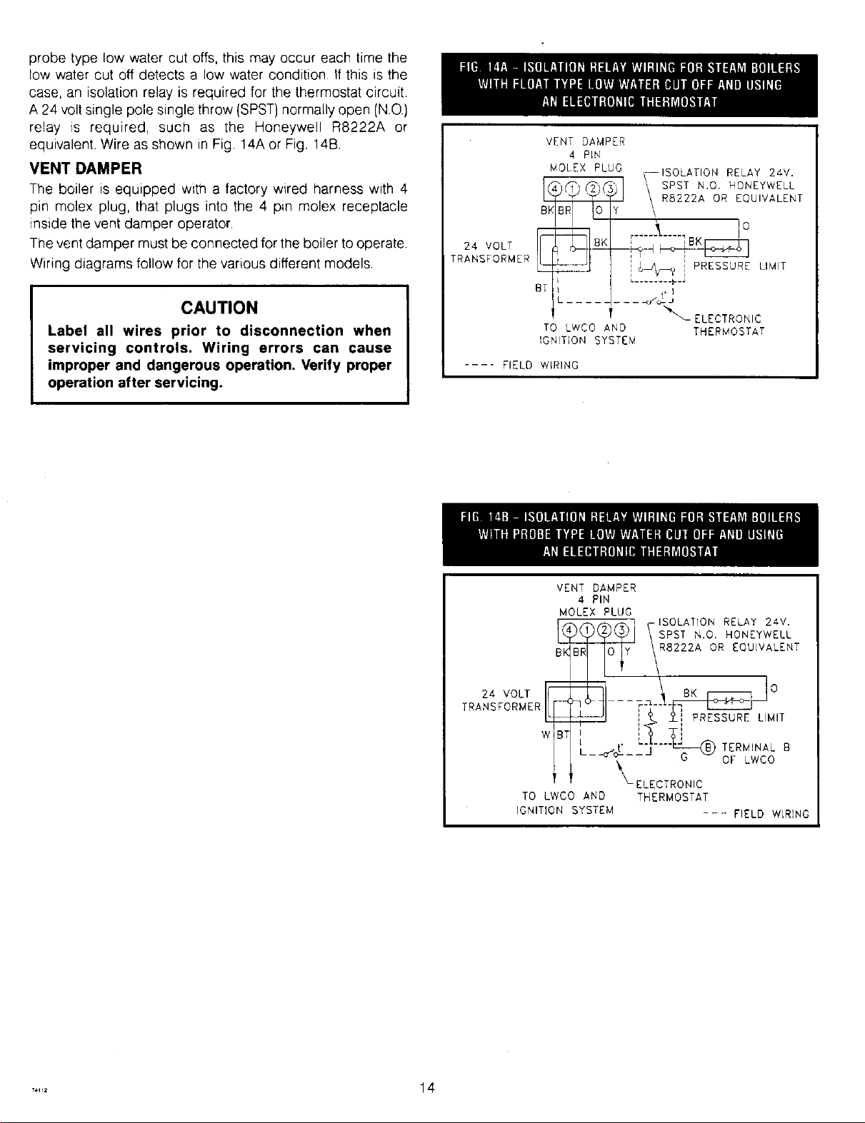
case,anisolationrelayisrequiredforthethermostatcircuit
A24voltsinglepolesinglethrow(SPST)normallyopen(N.O.)
relay _srequired,such as the HoneywellR8222Aor
equivalent.WireasshowninFig.14AorFig.14B.
VENT DAMPER
The boiler is equipped with a factory wired harness with 4
pin molex plug, that plugs into the 4 pin molex receptacle
inside the vent damper operator.
The vent damper must be connected for the boiler to operate.
Wiring diagrams follow for the various different models.
CAUTION
Label all wires prior to disconnection when
servicing controls. Wiring errors can cause
improper and dangerous operation, Verify proper
operation after servicing.
24 VOLT
TRANSFORMER
VENT DAMPER
4 PLN
MOLEX PLUG
TO LWCO AND
IGNITION SYSTEM
-ISOLATION RELAY 24V.
SPST N+O. HONEYWELL
Y I R8222A OR EQUIVALENT
' !O
,_-----t----IBK
]_,_? i PRESSURE LIMIT
L........ p.J
.... .+tJ
%\
ELECTRONIC
THERMOSTAT
.... FIELD WLRING
VENT DAMPER
4 PIN
MOLEX PLUG
BK
24 VOLT r_
TRANSFORMER L_
7
TO LWCO AND
IGNITION SYSTEM
_y _-ISpOs[TATI?o ' REoLNAYyW22EVL
R8222A OR EQUIVALENT
°
+ ++ __±,,",PRES_ LIMIT
L -," TERMINAL++
-o"o--- G OF LWCO
_- ELECTRONIC
THERMOSTAT
--- FIELD WLRING
..... 14
Loading ...
Loading ...
Loading ...