Loading ...
Loading ...
Loading ...
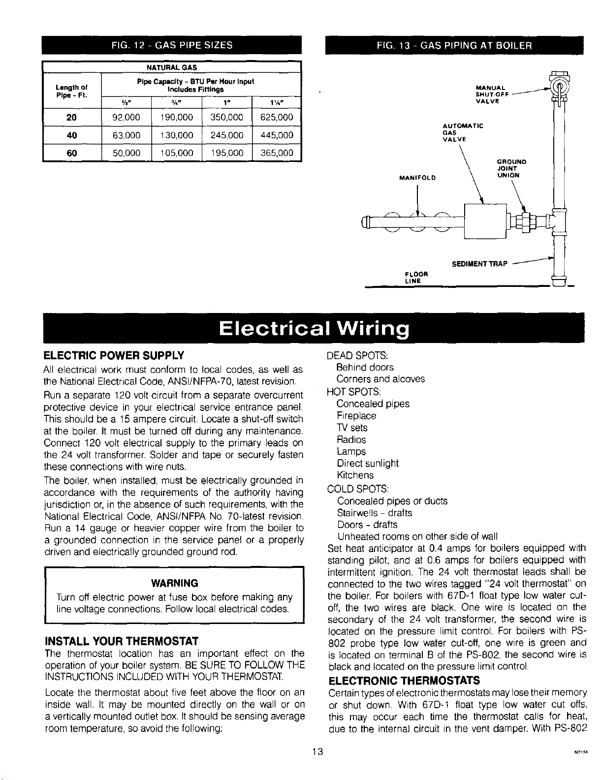
NATURAL GAS
Pipe Capactty- BTU Per Hourlnput
Length of Includes Fittings
Pipe - Ft.
½" ¾" 1" 1%"
20 92,000 190,000 350,000 625,000
40 63,000 130,000 245,000 445,000
60 50,000 ! 05,000 195,000 365,000
MANUAL
SHUT-OFF
VALVE
AUTOMATIC
VALVE
GROUND
JOINT
MANIFOLD UNION
S OI.ENTTRAP p l
FLOOR
LINE _u
ELECTRIC POWER SUPPLY
All electrical work must conform to local codes, as well as
the National Electrical Code, ANSI/NFPA-70, latest revision.
Run a separate 120 volt circuit from a separate overcurrent
protective device in your electrical service entrance panel.
This should be a 15 ampere circuit. Locate a shut-off switch
at the boiler. It must be turned off during any maintenance.
Connect 120 volt electrical supply to the primary leads on
the 24 volt transformer. Solder and tape or securely fasten
these connections with wire nuts.
The boiler, when installed, must be electrically grounded in
accordance with the requirements of the authority having
jurisdiction or, in the absence of such requirements, with the
National Electrical Code, ANSI/NFPA No. 70-latest revision.
Run a 14 gauge or heavier copper wire from the boiler to
a grounded connection in the service panel or a properly
driven and electrically grounded ground rod.
]
WARNING
Turn off electric power at fuse box before making any
line voltage connections. Follow local electrical codes.
I
INSTALL YOUR THERMOSTAT
The thermostat location has an important effect on the
operation of your boiler system. BE SURE TO FOLLOW THE
INSTRUCTIONS INCLUDED WITH YOUR THERMOSTAT.
Locate the thermostat about five feet above the floor on an
inside wall. It may be mounted directly on the wall or on
a vertically mounted outlet box. It should be sensing average
room temperature, so avoid the following:
DEAD SPOTS:
Behind doors
Corners and alcoves
HOT SPOTS:
Concealed pipes
Fireplace
TV sets
Radios
Lamps
Direct sunlight
Kitchens
COLD SPOTS:
Concealed pipes or ducts
Stairwells - drafts
Doors - drafts
Unheated rooms on other side of wall
Set heat anticipator at 0.4 amps for boilers equipped with
standing pilot, and at 0.6 amps for boilers equipped with
intermittent ignition. The 24 volt thermostat leads shall be
connected to the two wires tagged "24 volt thermostat" on
the boiler. For boilers with 67D-1 float type low water cut-
off, the two wires are black. One wire is located on the
secondary of the 24 volt transformer, the second wire is
located on the pressure limit control. For boilers with PS-
802 probe type low water cut-off, one wire is green and
is located on terminal B of the PS-802, the second wire is
black and located on the pressure limit control.
ELECTRONIC THERMOSTATS
Certain types ofelectronic therrnostats may lose their memory
or shut down. With 67D-! float type low water cut offs,
this may occur each time the thermostat calls for heat,
due to the internal circuit in the vent damper. With PS-802
Loading ...
Loading ...
Loading ...