Loading ...
Loading ...
Loading ...
For safe, efficient operation, the vent damper and all flue
product carrying areas of the appliance must be checked
annually by you, with particular attention given to deterioration
from corrosion or other sources. If you see corrosion or other
deterioration, contact your heating contractor for repairs.
Check vent damper operation as follows:
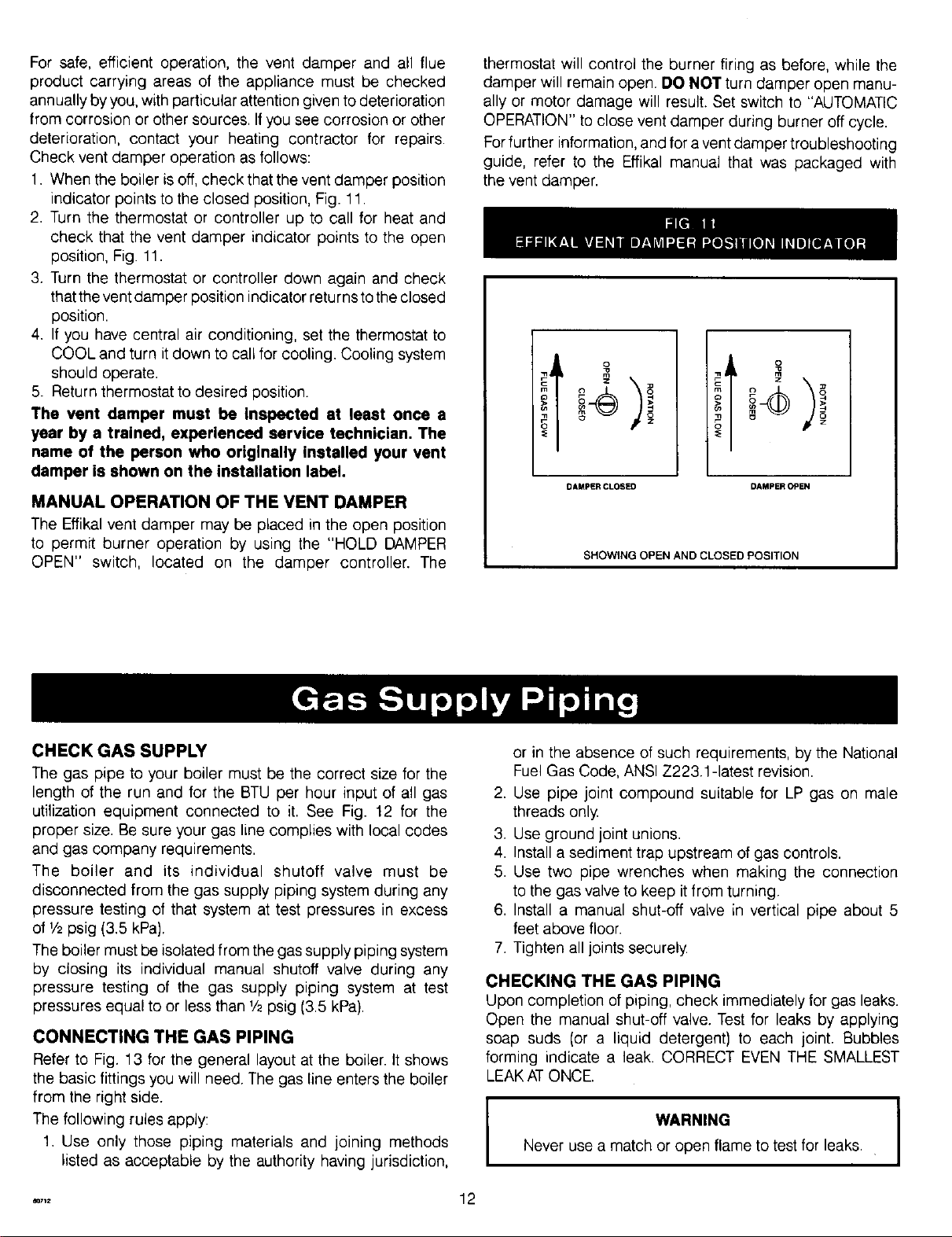
1. When the boiler is off, check that the vent damper position
indicator points to the closed position, Fig. 11.
2. Turn the thermostat or controller up to call for heat and
check that the vent damper indicator points to the open
position, Fig. 11.
3. Turn the thermostat or controller down again and check
that the vent damper position indicator returns to the closed
position.
4. If you have central air conditioning, set the thermostat to
COOL and turn it down to call for cooling. Cooling system
should operate.
5. Return thermostat to desired position.
The vent damper must be Inspected st least once a
year by a trained, experienced service technician, The
name of the person who originally installed your vent
damper is shown on the installation label.
MANUAL OPERATION OF THE VENT DAMPER
The Effikal vent damper may be placed in the open position
to permit burner operation by using the "HOLD DAMPER
OPEN" switch, located on the damper controller. The
thermostat will control the burner firing as before, while the
damper will remain open. DO NOT turn damper open manu-
ally or motor damage will result. Set switch to "AUTOMATIC
OPERATION" to close vent damper during burner off cycle.
For further information, and for a vent damper troubleshooting
guide, refer to the Effikal manual that was packaged with
the vent damper.
iI
DAMPER CLOSED DAMPER OPEN
SHOWING OPEN AND CLOSED POSITION
CHECK GAS SUPPLY
The gas pipe to your boiler must be the correct size for the
length of the run and for the BTU per hour input of all gas
utilization equipment connected to it. See Fig. 12 for the
proper size. Be sure your gas line complies with local codes
and gas company requirements.
The boiler and its individual shutoff valve must be
disconnected from the gas supply piping system during any
pressure testing of that system at test pressures in excess
of V2psig (3.5 kPa).
The boiler must be isolated from the gas supply piping system
by closing its individual manual shutoff valve during any
pressure testing of the gas supply piping system at test
pressures equal to or less than V2psig (3.5 kPa).
CONNECTING THE GAS PIPING
Refer to Fig. 13 for the general layout at the boiler. It shows
the basic fittings you will need. The gas line enters the boiler
from the right side.
The following rules apply:
1. Use only those piping materials and joining methods
listed as acceptable by the authority having jurisdiction,
or in the absence of such requirements, by the National
Fuel Gas Code, ANSI Z223.1-latest revision.
2. Use pipe joint compound suitable for LP gas on male
threads only.
3. Use ground joint unions.
4. Install a sediment trap upstream of gas controls.
5. Use two pipe wrenches when making the connection
to the gas valve to keep it from turning.
6. Install a manual shut-off valve in vertical pipe about 5
feet above floor.
7. Tighten all joints securely
CHECKING THE GAS PIPING
Upon completion of piping, check immediately for gas leaks.
Open the manual shut-off valve. Test for leaks by applying
soap suds (or a liquid detergent) to each joint. Bubbles
forming indicate a leak. CORRECT EVEN THE SMALLEST
LEAK ATONCE.
WARNING 1Never use a match or open flame to test for leaks.
.... 12
Loading ...
Loading ...
Loading ...