®
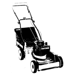
MODEL NUMBER 917.372852
OWNER'S MANUAL
oAssembly
Operation
Customer
Responsibilities
Service
oAdjustments
o Repair Parts
Caution:
Read and Follow
all Safety Rules
and Instructions
Before Operating
This Equipment
149788 REV, 2 05.23,95
ill......................................
[_#_,_..............................r_......................................._r.... " ...................
_ .... ....................................................................
Printed in USA
'1'III1'"11'
I
& SAFETY RULES
Safe Operation Practices for Walk-Behind Mowers
IMPORTANT; THIS CUTTING MACHINE lS CAPABLE OF AMPUTATING HANDS AND FEETAND THROWING OBJECTS
FAILURE TO OBSERVE THE FOLLOWING SAFETY INSTRUCTIONS COULD RESULT IN SERIOUS INJURY OR DEATH
SAFETY STANDARDS REQUIRE OPERATOR PRESENCE CONTROLS TO MINIMIZE THE RISK OF INJURY. YOUR UNtT IS
EQUIPPED WITH SUCH CONTROLS. DO NOT ATTEMPT TO DEFEAT THE FUNCTION OF THE OPERATOR PRESENCE
CONTROLS UNDER ANY CIRCUMSTANCES
TRAINING:
•' Read this operator's manual carefully Become familiar with
the controls and know how to operate your mower property.
Learn how to quickly stop mower
,, Do not allow children to use your mower Never allow adults
lo use mower without proper instructlons
• Keep the area of operation clear of all persons, especia!ly
small children and pets
• Use mower only as the manulaclurer intended and as de-
scribed in this manual.
o Do not operate mower if it has been dropped or damaged in
any manner. Always have damage repaired before using
your mower
• Do not use accessory attachments that are no? recornmended
by the manufaclurer Use of such attachments may be
hazardous..
• The blade turns when the engine is running
PREPARATION:
. Always thoroughly check the area to be mowed and clear it of
att stones, sticks, wires, bones, and other foreign obiects
These objects wi]] be thrown by the blade and can cause
severe injury
• Always wear safely glasses or eye shields when starting and
while using your mower
- Dress properly Do not operate mower when barefoot or
wearing open sandals. Wear only solid shoes with good
traction when mowing,
• Check fuel tank before starting engine. Do not filf gas lank
indoors, when the engine is running or when the engine is hot
Allow the engine 1o coot for several minutes before filling the
gas tank Clean off any spilled gasoline before starting the
engine
• Always make wheel height adjustments before starling your
mower Never attempt to do this while the engine is running
- Mow only in daylight or good adificial tight
OPERATION:
• Keep your eyes and mind on your mower and the area being
cut Do not let other interests distract you.
• Do not rnow wet or slippery grass Never run while operating
your mower. Atways be sure of your footing - keep a firm hold
on the handles and walk
• Do not put hands or feet near or under rotating pads Keep
clear of the discharge opening at al! times
• Always stop the engine whenever you leave or are not using
your mower, or before crossing driveways, walks, roads, and
any gravel-covered areas
• Never direct discharge of material toward bystanders nor
allow anyone near the mower while you are operating it
• Before cleaning, inspecting, or repa)dng your mower, stop the
engine and make absolutely sure the blade and all moving
parts have stopped Then disconnect the spark plug wire and
keep it away from the spark plug to prevent accidenta!
starting
• De not continue to run your mower if you hit a foreign obiect
Follow the procedure outlined above, lhen repair any dam-
age before restarting and operating you mower
• Do not change the gnvemor settings or overspeed the
engine Engine damage or personal injury may result.
• Do not operate your mower if it vibrates abnormally Exces-
sive vibration is an indication of damage; stop the engine,
safely check for the cause of vibration and repair as required
, Do not run the engine indoors Exhaust fumes are danger-
ous
• Never cut grass by pulling the mower towards you Mow
across the face of slopes, never up and down or you might
lose your footing. Do not mow excessively steep slopes. Use
caution when operating the mower on uneven terrain or when
changing directions - maintain good footing
• Never operate your mower without proper guards, plates,
grass catcher or olher safety devices in place
MAINTENANCE AND STORAGE:
• Check the blade and the engine mounting bolts often to be
sure they are tightened properly
• Check all bolts, nuts and screws at frequent intervals for
proper tightness to be sure mower is in safe working condi-
tion.
• Keep all safety devices in place and working.
• To reduce fire hazard, keep the engine free of grass, leaves
or excessive grease and oil
° Check grass catcher often for deterioration and wear and
replace worn bags Use only replacement bags that are
recommended by and comply with specifications of the
manufacturer of your mower
• Always keep a sharp blade on your mower
• Allow engine to coot before storing in any enclosure
• Never slore mower with fuel in the tank inside a building
where fumes may reach an open flame or an ignition source
such as a hot water heater, space heater, clothes dryer, etc
LJ L J ±LI'L' L L" "HJL'* J'l UUU I:' ,,U,,,
Look for this symbol to point out im-
portant safety precautions. It means
CAUTION!tt BECOME ALERT!t! YOUR
SAFETY IS INVOLVED.
CAUTION: Always disconnect spark
plug wire and place wire where it can-
not contact spark plug in order to pre_
vent accidental starting when setting
up, transporting, adjusting or making
repairs.
i i
WARNING
The engine exhaust from this product con-
tains chemicals known to the State of Califor-
nia to cause cancer, birth defects, or other
reproductive harm.
CONGRATULATIONSonyourpurchaseofaSearsLawn
Mowerithasbeendesigned,engineered and manufac-
tured to give you the best possible dependability and
pefformance_
Should you experience any problem you cannol easily
remedy, please contact your nearest Sears Authorized
Service Center/Department We have competent, well-
trained technicians and the proper tools to service or repair
this lawn mower.
Please read and retain this manual The instructions wilt
enable you lo assemble and maintain your lawn mower
properly. Always observe the "SAFETY RULES'L
MODEL
NUMBER 917.372852
SERIAL
NUMBER
DATE OF PURCHASE
THE MODELAND SERIAL NUMBERS WILL BE FOUND
ON A DECAL ATTACHED TO THE REAR OF THE
LAWN MOWER HOUStNG
YOU SHOULD RECORD BOTH SERIAL NUMBER AND
DATE OF PURCHASE AND KEEP IN A SAFE PLACE
FOR FUTURE REFERENCE,.
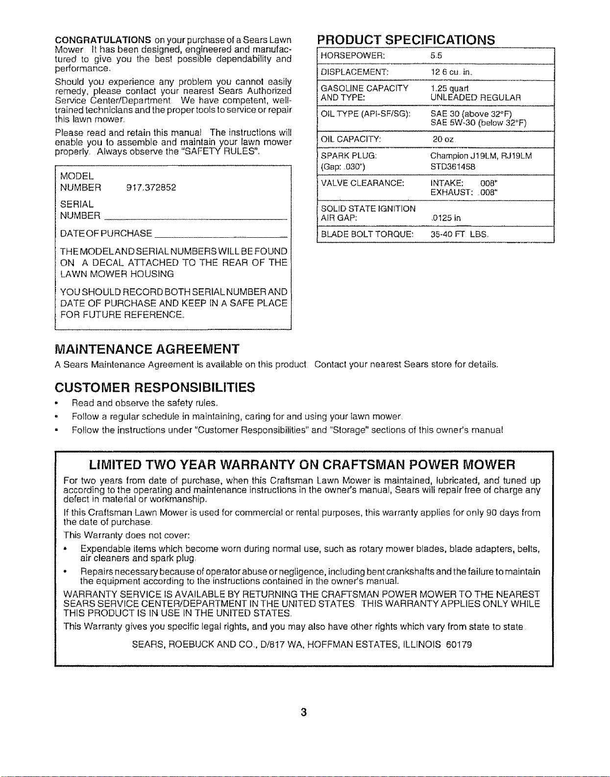
PRODUCT SPECIFICATIONS
HORSEPOWER: 5,5
DISPLACEMENT: 12 6 cu in..
GASOLINE CAPACITY 1.25 quart
AND TYPE: UNLEADED REGULAR
OiL TYPE (API-SF/SG): SAE 30 (above 32°F)
SAE 5W-30 (below 32"F)
OIL CAPACITY: 20 oz
SPARK PLUG: Champion J19LM, RJt9LM
(Gap: .030") STD361458
VALVE CLEARANCE: INTAKE: 008"
EXHAUST: .008"
SOLID STATE IGNITION
AIR GAP: 0125 in
BLADEBOLTTORQUE: 35-40 FT LBSo
MAINTENANCE AGREEMENT
A Sears Maintenance Agreement is available on this product Contact your nearest Sears store for details,
CUSTOMER RESPONSIBILITIES
. Read and observe the safety rules,
= Fotlow a regular schedule in maintaining, caring for and using your lawn mower.
• Fo!low the instructions under "Customer Responsibilities" and "Storage" sections of this owner's manual
LIMITED TWO YEAR WARRANTY ON CRAFTSMAN POWER MOWER
For two years from date of purchase, when this Craftsman Lawn Mower is maintained, lubricated, and tuned up
according to the operating and maintenance instructions in the owner's manual, Sears will repair free of charge any
defect in material or workmanship°
If this Craftsman Lawn Mower is used for commercial or rental purposes, this warranty applies for only 90 days from
the date of purchase
This Warranty does not cover:
• Expendable items which become worn during normal use, such as rotary mower blades, blade adapters, belts,
air cleaners and spark plug.
• Repairs necessary because of operator abuse or negligence, including bentcrankshafts and the failure to maintain
the equipment according to the instructions contained in the owner's manual.
WARRANTY SERVICE IS AVAILABLE BY RETURNING THE CRAFTSMAN POWER MOWER TO THE NEAREST
SEARS SERVICE CENTER/DEPARTMENT IN THE UNITED STATES THIS WARRANTY APPLIES ONLY WHILE
THIS PRODUCT IS tN USE IN THE UNITED STATES.
This Warranty gives you specific legal rights, and you may also have other rights which vary from state to state
SEARS, ROEBUCK AND CO., D/817 WA, HOFFMAN ESTATES, ILLINOIS 60179
TABLE OF CONTENTS
SAFETY RULES ................................................................ 2
PRODUCT SPECIFICATIONS ...................................... 3
CUSTOMER RESPONSIBILITIES ..................... 3, 12-14
WARRANTY ................................................................... 3
ASSEMBLY ..................................................................... 6
OPERATION ....................................................................... 8
MAINTENANCE SCHEDULE ...................................... 12
SERVICE AND ADJUSTMENTS .................................. 15
STORAGE ..................................................................... 17
TROUBLESHOOTING ................................................. 27
REPAIR PARTS - LAWN MOWER ........................ 18_22
REPAIR PARTS - ENGINE ...................................... 23-25
PARTS ORDERING/SERVICE ................................... 28
INDEX
A
Accessories ......................................... 5
Adjustments:
Carburetor ................................ 16
Engine Speed .............................. 16
Handle Height ........................... 16
Height ot Cut ........................... 9
Air Filter."
Replacement ............................ t4
Service ...................................... t4
AssembIy .................................................... 6
B
Blade:
Sharpening .............................. I3
Replacement ....................... 13
C
Controls:
Drive Control ................................... g
Engine Zone Control ..................... 9
Engine Speed Control .................... 9
Operator Presence Control Bar ......8
Customer Responsibilities ....... 3, 12-14
Air Fqlter ....................................... 14
Blade Care/Replacement ........... 13
Drive Wheels ............................... 13
Engine ....................................... 14
Lubrication .................................. 14
Spark Plug .............................. 14
Cutting Levels ........................................... 9
E
Engine:
Air Filter .................................... t4
Oil Change ................................ 14
Oil Level ........................................ 14
Oil Type ......................................... 14
Starting ..................................................10
Stopping ............................. 10
Storage ........................... t 7
F
Fuel:
Capacity ............................................. 3
Storage .......................................... 17
Type .............................. 10
L
Lubrication:
Engine ................................... 14
Lawn Mower ........................... 12
M
Maintenance Agreement .................. 3
Maintenance Schedule ...................... 12
Mowing Tips ..................................... t I
Oil:
O
Engine ........................................ 10
Storage ................................ 17
Operation:
Drive Control ..................................
Engine Control ........................................
Grass Catcher ............................. 10
Mower .......................................... 9
Operator Presence Control Bar 9
Options:
Accessories ...................................... 5
R
Repair Parts:
Engine ................................... 23-25
Lawn Mower ................................. 18-22
Responsibilities, Customer ........3, 12-I4
S
Safety Rules ...................................... 2
Service and Adjustments .................... 15
Carburetor ................................ 16
Engine Speed ........................... 16
Handle ........................................ 16
Spark Plug ...................................... 14
Specifications .................................. 3
Speed Control:
Engine ............................................ 10
Starting the Engine ......................... 10
Stopping the Engine ............................. 10
Storage ................................................ 17
T
Troubleshooting Chart ......................... 27
W
Warranty........................................... 3

___11 ;LlJJJ;II ,,,,,
LAWN MOWER ACCESSORIES
These accessories were available when this lawn mower was produced.. They are a!so available at most Sears retail outlets
and service centers.. Most Sears stores can also order repair parts for you, when you provide the model number of your lawn
mower_ Some of these accessories may not apply to your lawn mower
LAWN MOWER PERFORMANCE
,= ,,, ,= , ,, ,,,, , ,,,,,,,,, ,, = ,, ,,,H,, ,,, , ,= = =, ,, , , ,,,,,, ,,,,,,
CLIPPING DEFLECTOR
FOR REAR DISCHARGE LAWN MOWERS
,,,,,, , ll,,l,,, i, ,H,,, H
GRASS CATCHERS
FOR
REAR DISCHARGE
LAWN MOWERS
i
LAWN MOWER MAINTENANCE
MULCHER KITS
JLL
GRASS CATCHERS
FOR
SIDE DISCHARGE
LAWN MOWERS
,,,, ,,,, ,
MUFFLERS
BELTS
AIR RLTERS
,11 ii i ii
BLADES BLADE ADAPTERS WHEELS
STABILIZER
GAS CANS
SPARK PLUGS
ENGINE OIL
5
u_l[,iJJiJll ill i unl ,u- ii, i
ASSEMBLY
Read these instructions and this manual in its entirety
before you attempt to assemble or operate your new lawn
mower. Your new lawn mower has been assembled at the
factory with the exception of those parts teft unassembted
for shipping purposes. To ensure safe and proper opera-
tion of your lawn mower, atl paris and hardware you
assemble must be tightened securely. Use the correct
tools as necessary to ensure proper tightness. Aft parts
such as nuts, washers, bolts, etc., necessary to complete
the assembly have been placed in the parts bag
TO REMOVE LAWN MOWER FROM
CARTON
= Remove loose parts included with mower
, Cut down two end corners of cation and lay end panel
down fiat
• Remove all packing materials except padding between
upper and lower handle and padding holding operator
presence control bar to upper handle,
• Roll lawn mower out of carton and check carton thor-
oughly for additional loose pads°
HOW TO SET UP YOUR LAWN MOWER
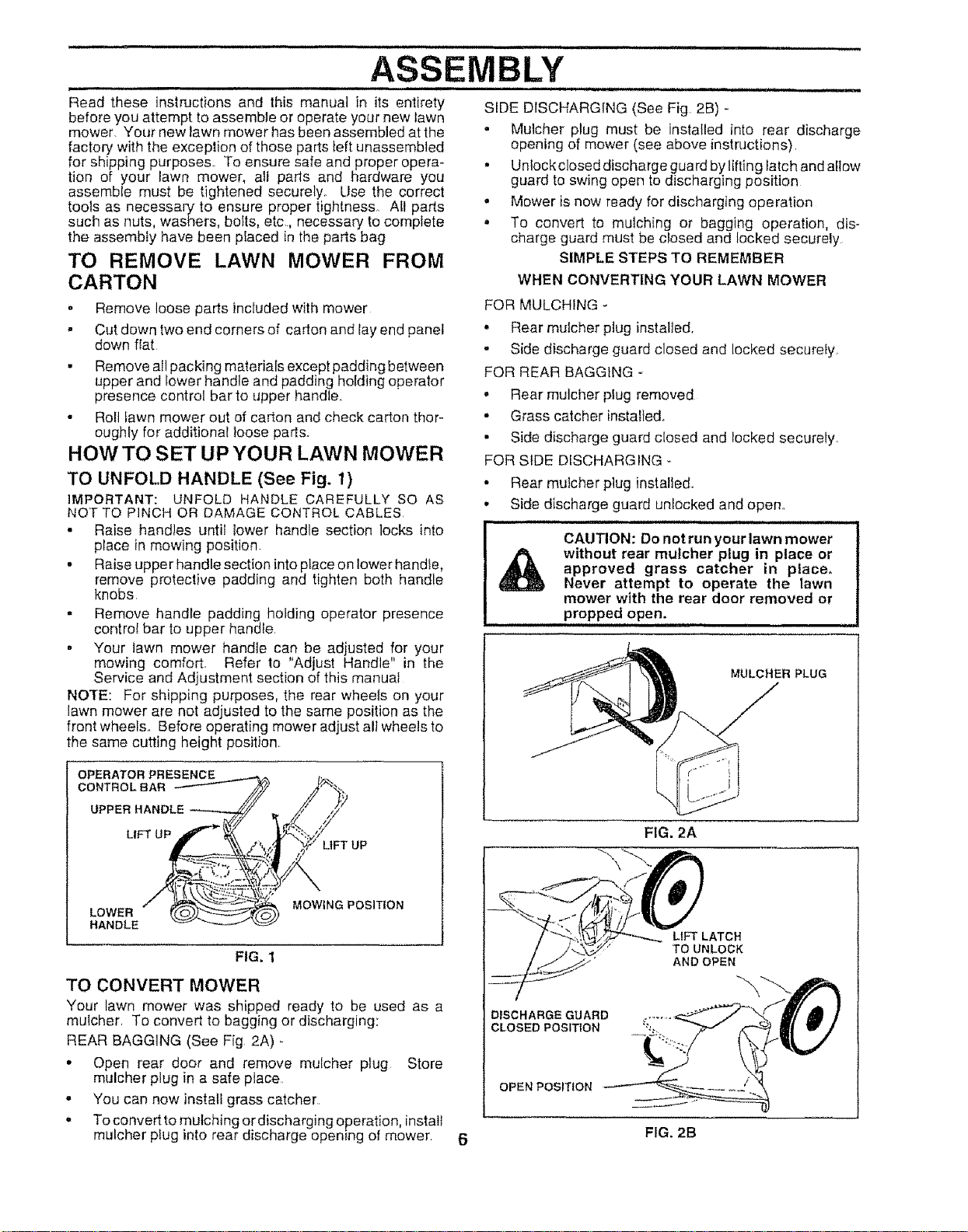
TO UNFOLD HANDLE (See Fig. 1)
iMPORTANT: UNFOLD HANDLE CAREFULLY SO AS
NOT TO PINCH OR DAMAGE CONTROL CABLES
• Raise handles until tower handle section locks into
place in mowing position
,, Raise upper handle section into placeon lower handle,
remove protective padding and tighten both handle
knobs
. Remove handle padding holding operator presence
control bar to upper handle
• Your lawn mower handle can be adjusted for your
mowing comfort Refer to "Adjust Handle" in the
Service and Adjustment section of this manual
NOXE: For shipping purposes, the rear wheels on your
lawn mower are not adjusted to the same position as the
front wheels. Before operating mower adjust eli wheels to
the same cutting height position
OPERATOR PRESENCE
CONTROLBAR
UPPER HANDLE
LIFT UP
LIFTUP
LOWER
HANDLE
MOWING POSITION
FIG. 1
TO CONVERT MOWER
Your lawn mower was shipped ready to be used as a
mulcher To convert to bagging or discharging:
REAR BAGGING (See Fig 2A)
• Open rear door and remove mulcher ptug Store
mulcher plug in a safe place
- You can now install grass catcher
,_ To convert to mulching ordischarging operation, install
mulcher pfug into rear discharge opening of mower
SIDE DISCHARGING (See Fig 2B) -
• Mulcher plug must be installed into rear discharge
opening of mower (see above instructions),
• Unlock closed discharge guard by lifting latch and allow
guard to swing open to discharging position
,, Mower is now ready for discharging operation
• To convert to mulching or bagging operation, dis-
charge guard must be closed and locked securely
SIMPLE STEPS TO REMEMBER
WHEN CONVERTING YOUR LAWN MOWER
FOR MULCHING -
• Rear mulcher plug installed
o Side discharge guard closed and locked securely
FOR REAR BAGGING -
, Rear mulcher plug removed
- Grass catcher installed°
• Side discharge guard closed and locked securely
FOR SIDE DISCHARGING -
o
o
Rear mutcher plug installed,
Side discharge guard unlocked and open°
Jlll, JJ ]/ i, in ,tl,, _!n,lt
CAUTION: Do not run your lawn mower
without rear mulcher plug in place or
approved grass catcher tn place°
Never attempt to operate the lawn
mower with the rear door removed or
propped open.
MULCHER PLUG
DISCHARGE GUARD
CLOSED POSITION
OPEN POSITION
LtFT LATCH
TO UNLOCK
AND OPEN
6 FIG. 2B
ASSEMBLY
i i i UlllU iiii iii u, i i iii 1,1, ,1, illU lU, i u ii ii i i i i
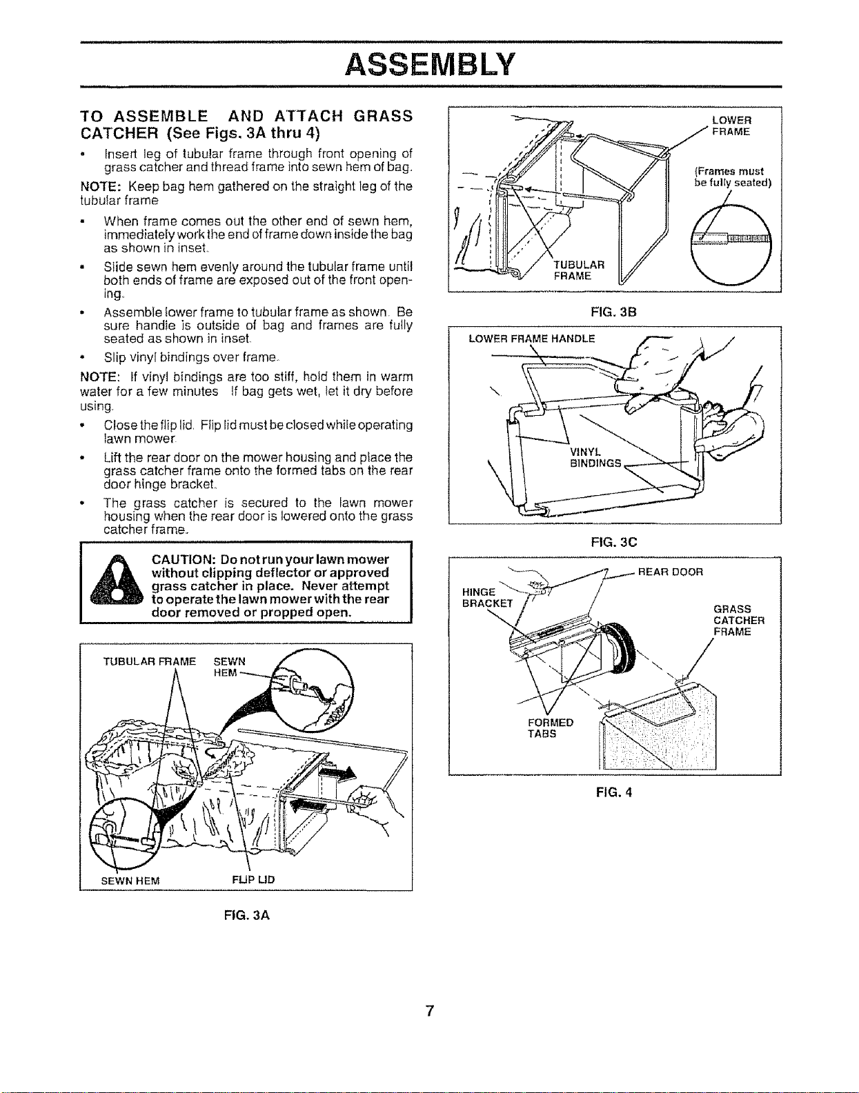
TO ASSEMBLE AND ATTACH GRASS
CAI'CHER (See Figs. 3A thru 4)
• Insert leg of tubular frame through front opening of
grass catcher andthread frame into sewn hem of bag,
NOTE: Keep bag hem gathered on the straight leg of the
tubutar frame
• When frame comes out the other end of sewn hem,
immediately work the end offrame down inside the bag
as shown in inset.
° Slide sewn hem evenly around the tubular frame until
both ends of frame are exposed out of the front open-
ing.
• Assemble iower frame to tubular frame as shown. Be
sure hand+e is outside of bag and frames are fully
seated as shown in inset
° Slip vinyl bindings over frame
NOTE: If vinyl bindings are too stiff, hold them in warm
water for a few minutes if bag gets wet, let it dry before
using.
• Close the flip lid. Ftip lid must be closed while operating
lawn mower
• Lift the rear door on the mower housing and place the
grass catcher frame onto the formed tabs on the rear
door hinge bracket..
• The grass catcher is secured to the lawn mower
housing when the rear door is lowered onto the grass
catcher frame..
CAUTION: Do not run your lawn mower
without clipping deflector or approved
grass catcher in place. Never attempt
to operate the lawn mower with the rear
door removed or propped open.
TUBULAR FRAME SEWN
SEWN HEM
FLIP LID
BRACKET
FIG. 3C
DOOR
GRASS
CATCHER
FRAME
\
FORMED
TABS
FIG. 4
FIG, 3A
7
OPERATION
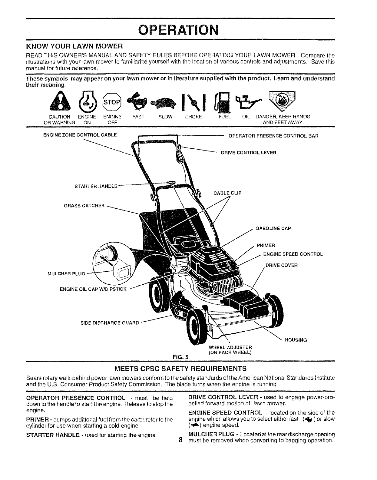
KNOW YOUR LAWN MOWER
READ THtS OWNER'S MANUAL AND SAFETY RULES BEFORE OPERATING YOUR LAWN MOWER. Compare the
illustrationswith your lawn mower to familiarize yourself with the location of various controls and adjustments. Save this
manual for future reference.
These symbols may appear on your lawn mower or in literature supplied with the product. Learn and understand
their meaning°
CAUTION ENGINE ENGINE FAST SLOW CHOKE
OR WARNING ON OFF
ii ,, ,i i, H ,i ,i i ill ,i,u .....................
ENG1NE ZONE CONTROL CABLE
FUEL OIL DANGER, KEEP HANDS
AND FEET AWAY
OPERATOR PRESENCE CONTROL BAR
DRIVE CONTROL LEVER
STARTER HANDLE
GRASS CATCHER
CABLE CLIP
GASOLINE CAP
MULCHER PLUG
PRIMER
• ENGINE SPEED CONTROL
DRIVE COVER
ENGINE OIL CAP W/DIPSTICK
SIDE DISCHARGE GUARD
WHEEL ADJUSTER
{ON EACH WHEEL}
FIG. 5
MEETS CPSC SAFETY REQUIREMENTS
HOUSING
Sears rotary walk-behind power lawn mowers conform to the safety standards of the American National Standards Institute
and the US Consumer Product Safety Commission° The blade turns when the engine is running
OPERATOR PRESENCE CONTROL - must be held
down to the handle to start the engine, Release to stop the
engine.
PRIMER - pumps additional fuel from the carburetor to the
cylinder for use when starting a cold engine
STARTER HANDLE - used for starting the engine.
DRIVE CONTROL LEVER - used to engage power-pro-
pelled forward motion of tawn mower_
ENGINE SPEED CONTROL - located on the side of the
engine which allows you to select either fast (,_J_)or slow
(.,a,,) engine speed..
MULCHER PLUG _Located atthe rear discharge opening
must be removed when converting to bagging operation
i i
OPERATION
ill i i i
ii i
The operation of any lawn mower can result in foreign objects thrown into the eyes, which can
result in severe eye damage. Always wear safety glasses or eye shields while operating your
lawn mower or performing any adjustments or repairs, We recommend a wide vision safety
mask over the spectacles or standard safety gtasses,
HOW TO USE YOUR LAWN MOWER
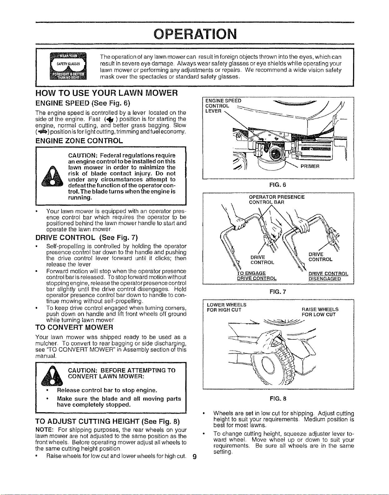
ENGINE SPEED (See Fig. 6)
The engine speed is controlled by a lever located on the
side of the engine,. Fast (_t') position is for starting the
engine, normal cutting, and better grass bagging. Slow
(,_t,) position isforlightcutting, trimming and fueleconomy.
ENGINE ZONE CONTROL
J , , ,LILLII II J,lJ
CAUTION: Federal regulations require
an engine control to beinstalled on this
_l_ lawn mower in order to minimize the
risk of blade contact injury. Do not
under any circumstances attempt to
defeatthe function of the operator con-
trol. The blade turns when the engine is
running.
i
, Your lawn mower is equipped with an operator pres-
ence control bar which requires the operator to be
positioned behind the fawn mower handle to start and
operate the lawn mower
DRIVE CONTROL (See Fig. 7)
• Self-propelling is controlled by holding the operator
presence control bar down to the handle and pushing
the drive control lever forward until it clicks; then
release the lever
• Forward motion will stop when the operator presence
control baris released.. To stop forward motion without
stopping engine, release the operator presence control
bar slightly until the drive control disengages.. Hold
operator presence control bar down to handte to con-
tinue mowing without self-propelling.
• To keep drive control engaged when turning corners,
push down on handle and lift front wheels off ground
while turning lawn mower
TO CONVERT MOWER
Your lawn mower was shipped ready to be used as a
mulcher. To convert to rear bagging or side discharging,
see 'TO CONVERT MOWER" in Assembly sect)on of this
manual.
CAUTION: BEFORE ATTEMPTING TO
CONVERT LAWN MOWER:
° Release control bar to stop engine.
• Make sure the blade and all moving parts
have completely stopped.
TO ADJUST CUTTING HEIGHT (See Fig. 8)
NOTE: For shipping purposes, the rear wheels on your
lawn mower are not adjusted to the same position as the
front wheels. Before operating mower adjust allwheels to
the same cutting height position
= Raise wheels for low cut and lower wheels for high cut 9
ENG;NESPEED
CONTROL
LEVER
PRIMER
\
FIG. 6
OPERATOR PRESENCE
CONTROL BAR
DRIVE
CONTROL
TO ENGAGE
DRIVE CONTROL
DRIVE
CONTROL
DISENGAGED
FIG. 7
LOWER WHEELS
FOR HIGH CUT RAISE WHEELS
FOR LOW CUT
FIG. 8
• Wheels are set in low cut for shipping. Adjust cutting
height to suit your requirements. Medium position is
best for most lawns.
• To change cutting height, squeeze adjuster lever to-
ward wheel., Move wheel up or down to suit your
requirements. Be sure all wheels are in the same
setting.
OPERATION
i , i ii i i,p
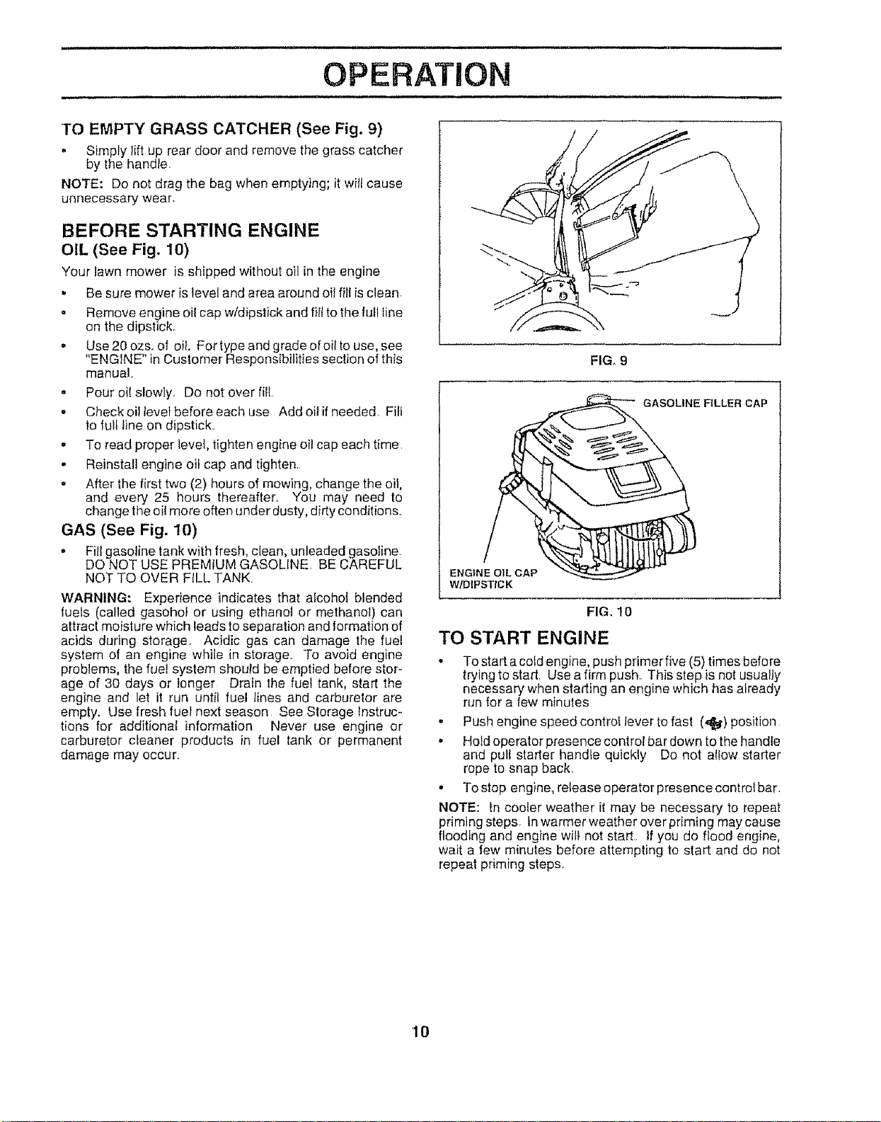
TO EMPTY GRASS CATCHER (See Fig, 9)
. Simply lift up rear door and remove the grass catcher
by the handle,
NOTE: Do not drag the bag when emptying; it will cause
unnecessary wear
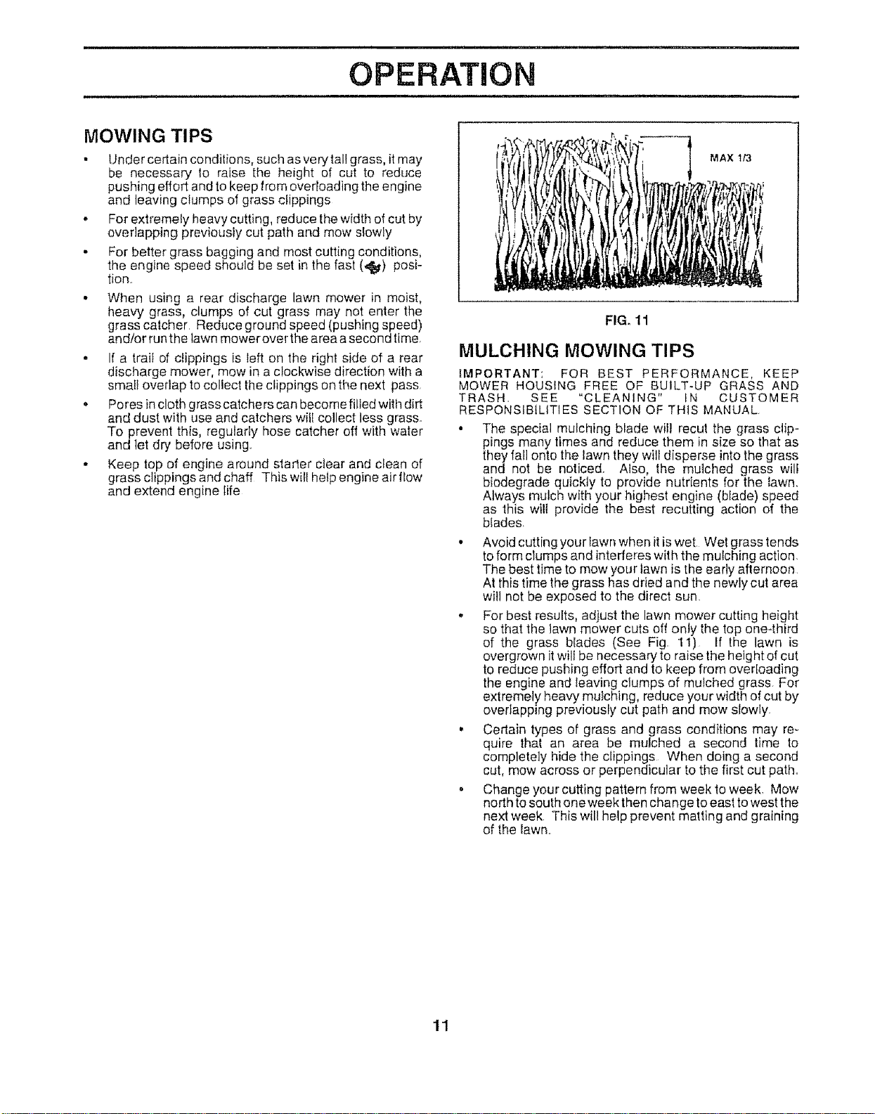
BEFORE STARTING ENGINE
OIL (See Fig. 10)
Your lawn mower is shipped without oil inthe engine
. Be sure mower islevel and area around oil fill isclean
o Remove engine oi! cap w/dipstick and flit to the full line
on the dipstick.
- Use 20 ozs. of oil. For type and grade of oil to use, see
"ENGINE" in Customer Responsibilities section of this
manual,
,, Pour oi! slowly Do not over fill
• Check oif level before each use Add oil ifneeded. Fill
to full line on dipstick.,
• To read proper level, tighten engine oil cap each time,
. Reinstall engine oil cap and tighten.
,, After the first two (2) hours of mowing, change the oil,
and every 25 hours thereafter° You may need to
change theoil more often under dusty, dirty conditions.,
GAS (See Fig. 10)
,, Fitl gasoline tankwith fresh, clean, unleaded gasoline.
DO NOT USE PREMtUM GASOLINE, BE CAREFUL
NOT TO OVER FILL TANK
WARNING: Experience indicates that aicoho] blended
fuels (called gasohot or using ethanol or methanol) can
attract moisture which leads to separation and formation of
acids during storage,, Acidic gas can damage the fuel
system of an engine while in storage., To avoid engine
problems, the fue! system should be emptied before stor-
age of 30 days or longer Drain the fuel tank, start the
engine and let it run until fuel iines and carburetor are
empty. Use fresh fuel next season See Storage instruc-
tions for additional information Never use engine or
carburetor cleaner products in fuel tank or permanent
damage may occur,
ENGINE OIL CAP
W/DIPSTICK
GxxASOLINE FILLER CAP
FIG, 10
TO START ENGINE
- To start acotd engine, push primer five (5) times before
trying to start Use a firm push,, This step isnot usually
necessary when stadir_gan engine which has already
run for a few minutes
° Push engine speed controt tever to fast (,,_) position
• Ho}doperator presence control bar down to the handle
and pult starter handte quickly Do not alEowstarter
rope to snap back,
• To stop engine, release operator presence control bar
NOTE: In cooler weather it may be necessary to repeat
priming steps tnwarmer weather over priming may cause
floodtng and engine wilt not start, if you do flood engine,
wait a few minutes before attempting to start and do not
repeat priming steps.
10
, i , iii i i i ,,, ii ii,llllllll i ill iii i.iii i,
OPERATION
i i m l ii ii i i i ii ii i i i , i
MOWING TIPS
• Under certain conditions, such asvery tallgrass, itmay
be necessary to raise the height of cut to reduce
pushing effort and to keep from overloading the engine
and leaving clumps of grass clippings
. For extremely heavy cutting, reduce thewidth ofcut by
overlapping previousiy cut path and mow slowly
• For better grass bagging and most cutting conditions,
the engine speed should be set in the fast (_4_) posi-
tion.
• When using a rear discharge lawn mower in moist,
heavy grass, clumps of cut grass may not enter the
grass catcher Reduce ground speed (pushing speed)
and/or runthe lawn mower over thearea asecond time
. If a trail of clippings is left on the right side of a rear
discharge mower, mow in a clockwise direction with a
small overlap tocollect the clippings on the next pass.
• Pores in cloth grass catchers can become filled with dirt
and dust with use and catchers will collect less grass.
To prevent this, regularly hose catcher off with water
and let dry before using
• Keep top of engine around starter ctear and clean of
grass clippings andchaff This will help engine air flow
and extend engine life
MAX t13
FIG. 11
MULCHING MOWING TIPS
IMPORTANT: FOR BEST PERFORMANCE, KEEP
MOWER HOUSING FREE OF BUILT-UP GRASS AND
TRASH, SEE "CLEANING" iN CUSTOMER
RESPONStB{LITIES SECTION OF THiS MANUAL
• The special mulching blade will recut the grass clip-
pings many times and reduce them in size so that as
theyfall onto the lawn they will disperse into the grass
and not be noticed. Also, the mulched grass will
biodegrade quickly to provide nutrients for the lawn.
Always mulch with your highest engine (blade) speed
as this will provide the best recurring action of the
blades
• Avoid cutting your lawn when it iswet Wet grass tends
toform clumps and intederes with the mulching action.
The best timeto mow your lawn is the early afternoon
At this time the grass has dried and the newly cut area
will not be exposed to the direct sun.
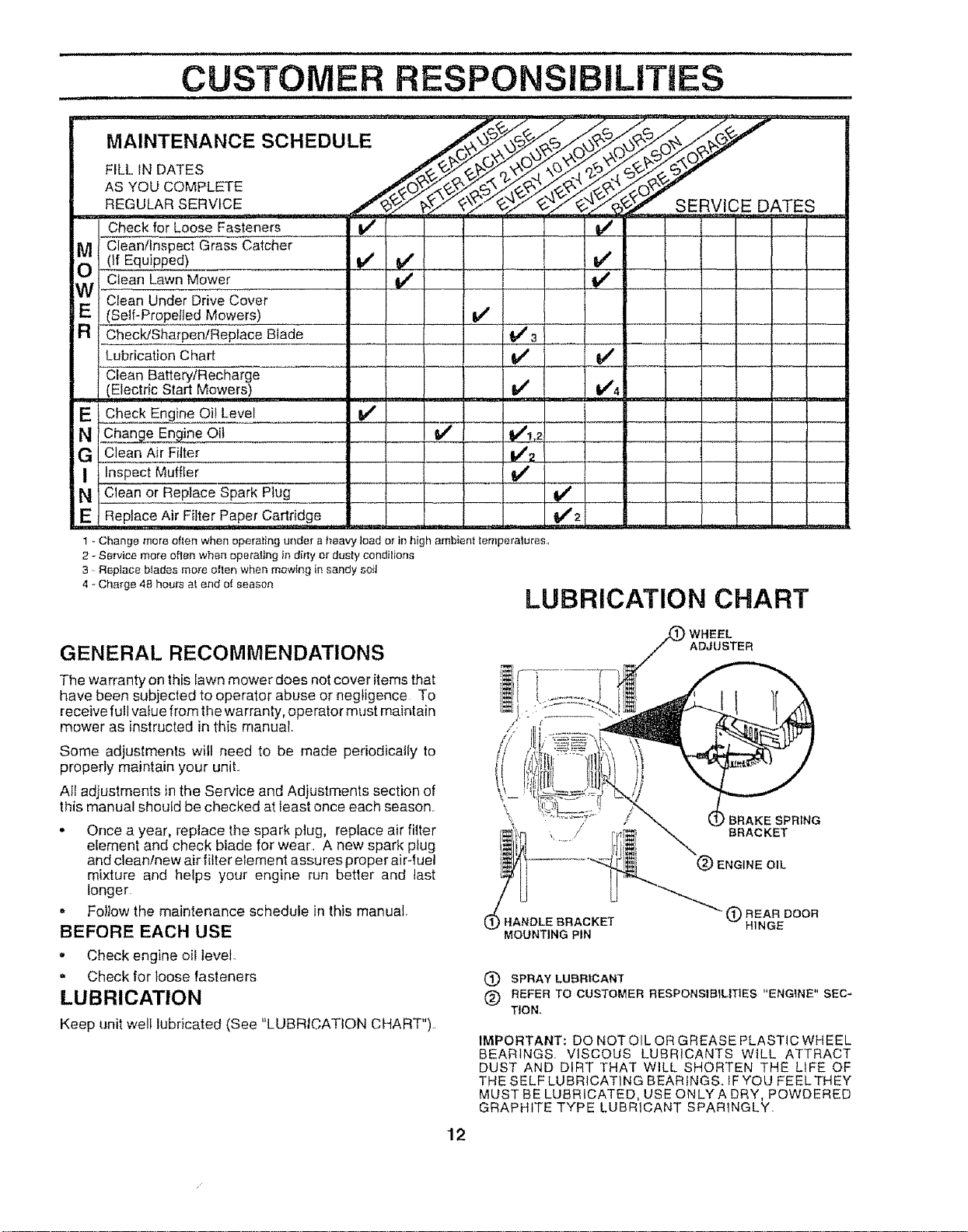
- For best results, adjust the lawn mower cutting height
so that the lawnmower cuts off only the top one-third
of the grass blades (See Fig. 11) ff the lawn is
overgrown itwill be necessary to raise the height ofcut
to reduce pushing effort and to keep from overloading
the engine and leavingclumps of mulched grass. For
extremely heavy mulching, reduce your width of cut by
overlapping previously cut path and mow slowly.
. Certain types of grass and grass conditions may re-
quire that an area be mulched a second time to
completely hide the clippings When doing a second
cut, mow across or perpendicular to the first cut path..
o Change your cutting pattern from week toweek. Mow
north to south one week thenchange toeast towest the
next week This will help prevent matting and graining
of the lawn..
11
L ,I U, .I
CUSTOMER RESPONSiBiLiTiES
i , , ii I
Check for Loose Fasteners
Clean/Inspect Grass Catcher
(if Equipped)
Clean Lawn Mower
.IV Clean Under Drive Cover
__(Self-Propelled Mowers)
Check/Sharpen/Replace Blade
Lubrication Chad
MA,.T .ANOESO.EDO.E
AsYouCOMPLFE /__ _._/_._.7"
REGULAR SERVICE ,,/'___..,_"_-'..,_'_ SERVICE DATES
v' J JL_
!
v" v" v'
i/ Iv'
v'
i,,u, i
V"
Clean Battery/Recharge
,. _ (Electric Start,,Mowers! ........
E Check Engine Oil Level
N C[nange En ine Oft
G Clean Air Filter
I Inspect Muffler
N Clean or Replace Spark Plug
E Replace Air Filter Paper Cartridge
_'3 .j
v'
V'! 2
v"
_2
1 - Change mere often when eperaling under a I_eavy lead or in high ambient lemperalures,
2 - Sewice more often when operating in dilly or dusty condilions
3. Replace blades rnot'e olten when mowing in sandy so}t
,.Ohar0e,ohou_otendo,soeson LUBRICATION CHART
GENERAL RECOMMENDATIONS
The warranty onthis lawn mower does notcover items that
have been subjected to operator abuse or negligence To
receive full vaguefrom tile warranty, operator must maintain
mower as instructed in this manual.
Some adjustments will need to be made periodically to
properly maintain your unit.
AII adjustments in the Service and Adjustments section of
this manual should be checked at least once each season.
- Once a year, replace the spark plug, replace air filter
element and check blade for wear, A new spark plug
and clean!new air filter eleme ntassures proper air-fuel
mixture and helps your engine run better and last
longer,
. FolJowthe maintenance schedule in this manual
BEFORE EACH USE
" Check engine oil level
Check for loose fasteners
LUBRICATION
Keep unit well lubricated (See "LUBRICATION CHART").,
/.
\
WHEEL
ADJUSTER
BRAKE SPRING
BRACKET
ENGINE OIL
HANDLE BRACKET
MOUNTING PIN
(_) REAR DOOR
HINGE
(_) SPRAY LUBRICANT
(_) REFER TO CUSTOMER RESPONSIBILITIES "ENGINE" SEC-
TION,
IMPORTANT: DO NOT OIL OR GREASE PLASTIC WHEEL
BEARINGS: VISCOUS LUBRICANTS WILL ATTRACT
DUST AND DIRT THAT WILL SHORTEN THE LIFE OF
THE SELF LUBRICATING BEARINGS. IF YOU FEEL THEY
MUST BE LUBRICATED, USE ONLYA DRY, POWDERED
GRAPHITE TYPE LUBRICANT SPAR1NGLY.
12
i, i,ii ilnl,, , ii i ii ii
CUSTOMER RESPONSIBILmES
i i i
LAWN MOWER
Always observe safety rules when performing any mainte-
nance,
TIRES
- Keep tires free of gasoline, oil, or insect control chemi-
cals which can harm rubber
, Avoid stumps, stones, deep ruts, sharp objects and
other hazards that may cause tire damage,
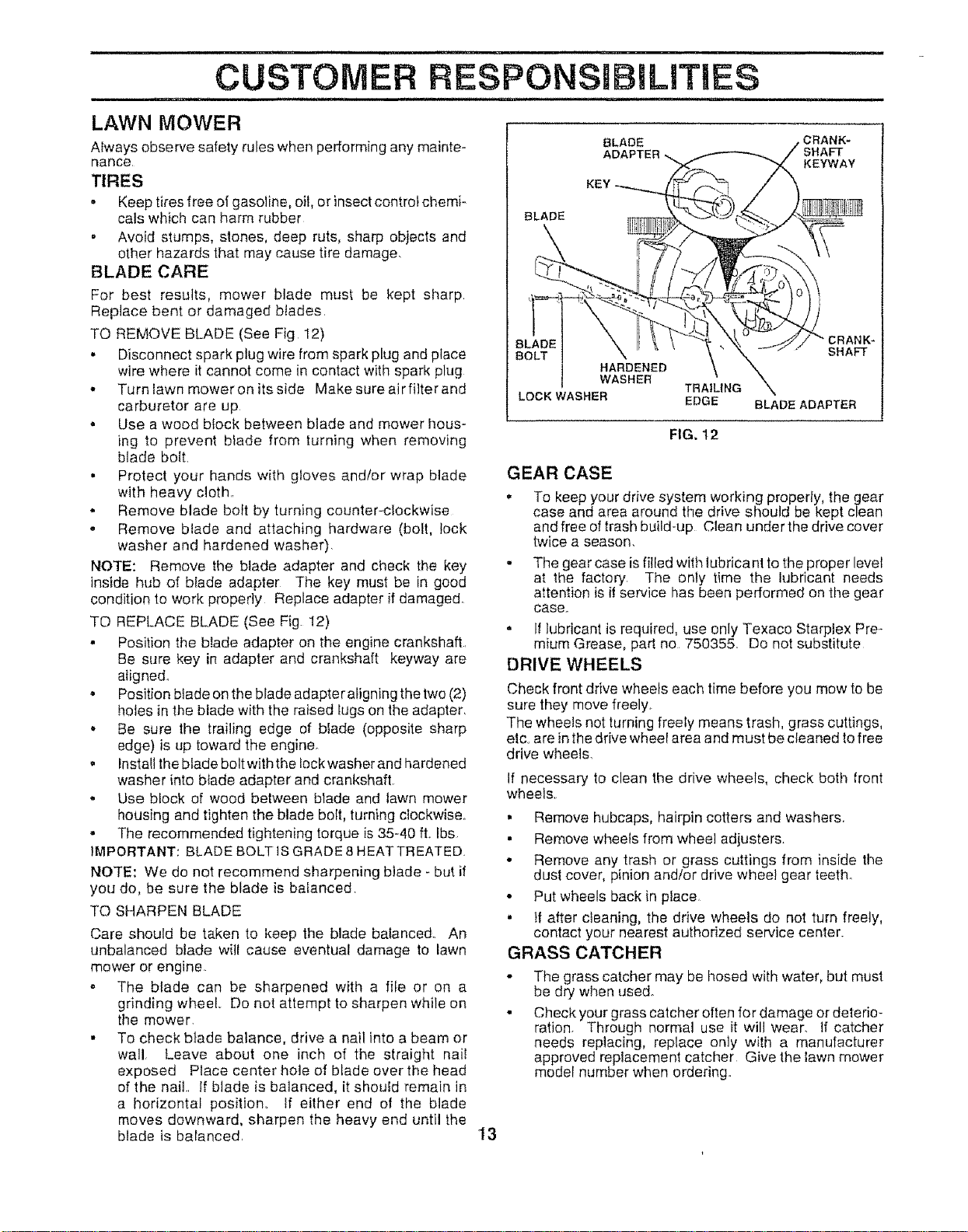
BLADE CARE
For best results, mower blade must be kept sharp
Replace bent or damaged blades,
TO REMOVE BLADE (See Fig I2)
• Disconnect spark plug wire from spark plug and place
wire where it cannot come in contact with spark plug
. Turn tawn mower on its side Make sure airfilter and
carburetor are up
• Use a wood block between blade and mower hous-
ing to prevent blade from turning when removing
blade bolt
° Protect your hands with gloves andfor wrap blade
with heavy cloth..
• Remove blade bolt by turning counter-clockwise
. Remove blade and attaching hardware (bolt, lock
washer and hardened washer)
NOTE: Remove the blade adapter and check the key
inside hub of blade adapter The key must be in good
condition to work properly Replace adapter if damaged.
TO REPLACE BLADE (See Fig. 12)
° Position the blade adapter on the engine crankshaft.
Be sure key in adapter and crankshaft keyway are
atigne&
• Position blade on the blade adapter atigning the two (2)
holes inthe blade with the raised tugs on the adapter.
. Be sure the trailing edge of blade (opposite sharp
edge) is up toward the engine.
. fnstaltthe blade bolt with the lockwasher and hardened
washer into blade adapter and crankshaft.
° Use block of wood between blade and lawn mower
housing and tighten the blade bolt, turning clockwise
° The recommended tightening torque is 35-40 ft, lbs
IMPORTANT: BLADE BOLT iS GRADE 8 HEAT TREATED.
NOTE: We do not recommend sharpening blade - but if
you do, be sure the blade is balanced
TO SHARPEN BLADE
Care should be taken to keep the blade balanced. An
unbalanced blade will cause eventual damage to lawn
mower or engine. .
- The blade can be sharpened with a fife or on a
grinding wheel,. Do not attempt to sharpen while on
the mower
• To check blade balance, drive a nail into a beam or
wall. Leave about one inch of the straight naiI
exposed Place center hole of blade over the head
of the nail.. If blade is balanced, it should remain in
a horizontal position° tf either end of the blade
moves downward, sharpen the heavy end until the
blade is balanced. 13
KEY _
LOCK WASHER
_ RANK-
SHAFT
KEYWAY
TRAtL1HG "\
EDGE BLADE ADAPTER
FIG, 12
GEAR CASE
, To keep your drive system working properly, the gear
case and area around the drive should be kept clean
and free oftrash build-up Clean under the drive cover
twice a season.
- The gear case isfilled with lubricant to tile proper level
at the factory The only time the lubricant needs
attention is il service has been performed on the gear
case.
• If lubricant is required, use only Texaco Starplex Pre-
mium Grease, part no 750355: Do not substitute
DRIVE WHEELS
Check front drive wheels each time before you mow to be
sure they move freely_
The wheels not turning freely means trash, grass cuttings,
etc. arein the drive wheel area and must be cteaned to free
drive wheels.
If necessary to clean the drive wheels, check both front
wheels.
• Remove hubcaps, hairpin cotters and washers.
• Remove wheels from wheel adjusters.
• Remove any trash or grass cuttings from inside the
dust cover, pinion and/or drive wheel gear teeth°
• Put wheels back in place,
• tf after cleaning, the drive wheels do not turn freely,
contact your nearest authorized service center.
GRASS CATCHER
The grass catcher may be hosed with water, but must
be dry when used.
Check your grass catcher often for damage or deterio-
ration. Through normal use it will wear. If catcher
needs replacing, replace only with a manufacturer
approved replacement catcher Give the lawn mower
model number when ordering.
I.LH.
CUSTOMER RESPONSiBILiTiES
_ m im ,, ,n ,
ENGINE
LUBRICATION
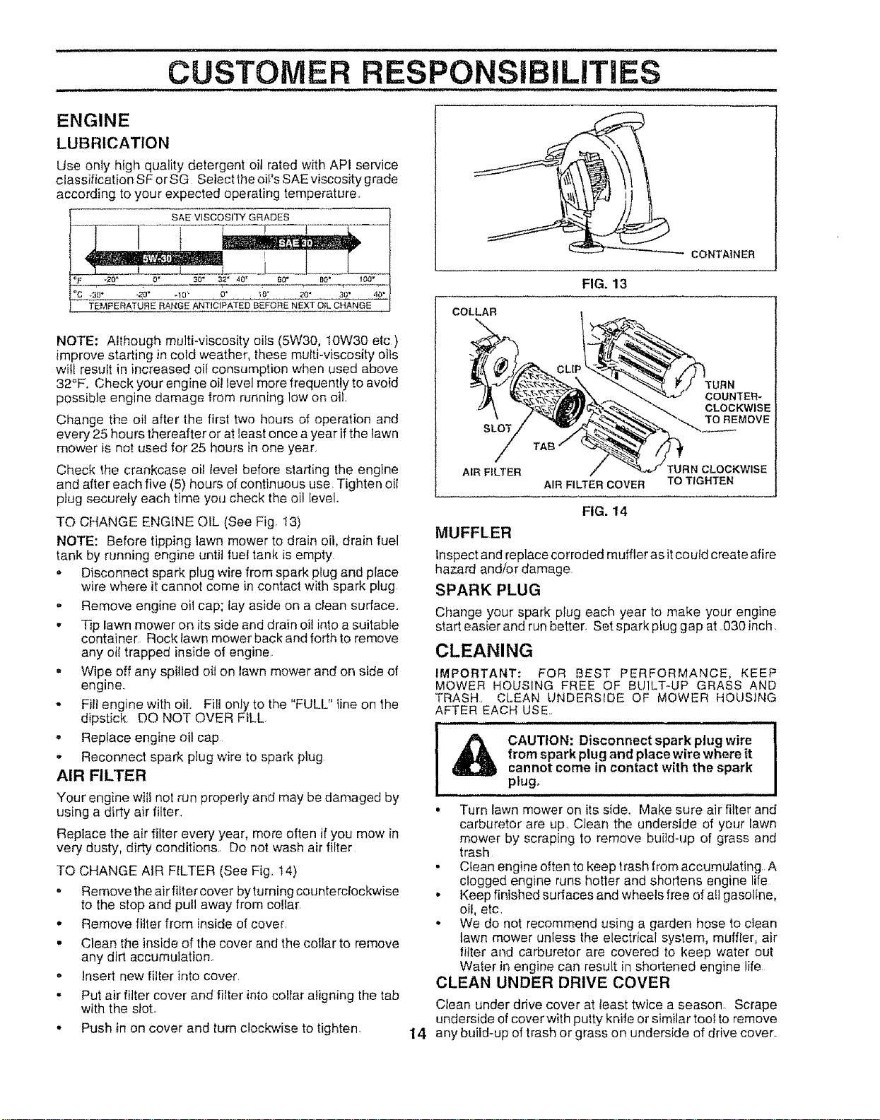
Use only high quality detergent oil rated with API service
classification SF orSG Seiect the oiI'sSAE viscosity grude
according to your expected operating temperature.,
SAE VISCOSITY GRADES
o" 3o_ 32" 40" 60"
TEMFERATURE RANGE ANTICIPATED BEFORE NEXT OIL CHANGE
NOTE; Although multi-viscosity oiis (5W30, 10W30 etc)
improve starting in cold weather, these multi-viscosity oils
will result in increased oil consumption when used above
32°F. Check your engine oii tevetmore frequently to avoid
possible engine damage from running low on oil.
Change the oil after the first two hours of operation and
every 25 hours thereafter or at least once a year ifthe lawn
mower is not used for 25 hours in one year_
Check the crankcase oil level before starting the engine
and after each five (5) hours ofcontinuous use. Tighten oil
plug securely each time you check the oil level°
TO CHANGE ENGINE OIL (See Fig, 13)
NOTE: Before tipping lawn mower to drain oil, drain fuel
tank by running engine until fuel tank is empty
- Disconnect spark plug wire from spark plug and place
wire where it cannot come in contact with spark plug
o Remove engine oil cap; lay aside on a clean surface..
- Tip lawn mower on its side and drain oil into a suitable
container Rock lawn mower back and forth to remove
any oil trapped inside of engine.
,, Wipe off any spilled oil on lawn mower and on side of
engine.
* Fill engine with oil. Fill only to the "FULL" line on the
dipstick DO NOT OVER FILL,
- Replace engine oil cap
- Reconnect spark plug wire to spark plug
AIR FILTER
Your engine wiIi not run properly and may be damaged by
using a dirty air filter.
Replace the air filter every year, more often if you mow in
very dusty, dirty conditions.. Do not wash air filter
TO CHANGE AIR FILTER (See Fig. t4)
,, Remeve theair fitter cover byturning counterclockwise
to the stop and pull away from coIIar.
• Remove filter from inside of cover.
• Clean the inside of the cover and the collar to remove
any dirt accumulation.
o Insert new filter into cover.
• Put air filter cover and filter into collar aligning the tab
with the slot.
o Push in on cover and turn clockwise to tighten.
r'_ CONTAINER
FIG. 13
COLLAR.__ ""CL[__
, / _ ,€._'-.,.",__-__ '-,.. To REMOVE
S
AIR FILTER / x%_ TURN CLOCKWISE
AIR FILTER COVER TO TIGHTEN
FIG. 14
MUFFLER
Inspect and replace corroded muffler as itcoutd create afire
hazard and!or damage=
SPARK PLUG
Change your spark plug each year to make your engine
start easier and run better_ Set spark pfuggap at.030 inch.
CLEANING
IMPORTANT: FOR REST PERFORMANCE, KEEP
MOWER HOUSING FREE OF BUILT-UP GRASS AND
TRASH,, CLEAN UNDERSIDE OF MOWER HOUSING
AFTER EACH USE,
,u i , i
CAUTION: Disconnectspark plug wire
from spark plug and place wire where it
cannot come in contact with the spark
plug.
r
• Turn lawn mower on its side.. Make sure air filter and
carburetor are up. Clean the underside of your lawn
mower by scraping to remove buitd4Jp of grass and
trash
• C[ean engine often to keep trash from accumulating A
clogged engine runs hotter and shortens engine life
* Keep finished surfaces and wheels free of all gasoline,
oii, etc
• We do not recommend using a garden hose to clean
lawn mower unIess the electrical system, muffler, air
filter and carburetor are covered to keep water out
Water in engine can result in shortened engine life
CLEAN UNDER DRIVE COVER
Clean under drive cover at least twice a season, Scrape
underside of cover with putty knife or similar toot to remove
14 any build-up of trash or grass on underside of drive cover,
SERVICE AND ADJUSTMENTS
CAUTION: BEFORE PERFORMING ANY SERVICE OR ADJUSTMENTS:
, Release controlbarr
• Make sure the blade and all moving parts have completely stopped.
= Disconnect spark plug wire from spark plug and place where it cannot come in contact with plug.
lAWN MOWER
TO ADJUST CUTTING HEIGHT
See "TO ADJUST CUTTING HEIGHT" in the Operation
section of this manual
REAR DEFLECTOR
The rear deflector, attached between the rear wheels of
your lawn mower, is provided to minimize the possibility
that objects wilt be thrown out the rear of lhe lawn mower
into the operator's mowing position It the rear deflector
becomes damaged, it should be replaced..
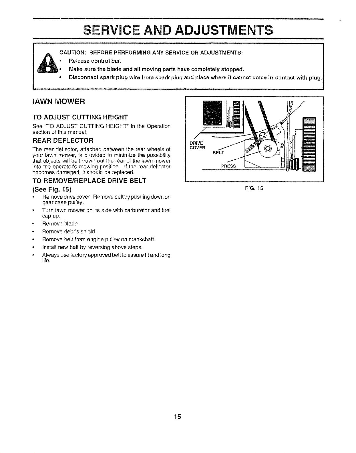
TO REMOVE/REPLACE DRIVE BELT
(See Fig. 15)
• Remove drive cover Remove belt by pushing down on
gear case pulley.
• Turn lawn mower on its side with carburetor and fuel
cap up..
, Remove blade
, Remove debris shield
• Remove belt from engine pulley on crankshaft
• Install new belt by reversing above steps.
= Always use factory approved belt to assure fit and long
life.
|
DRIVE
COVER
BELT
PRESS
F1G. 15
15
SERVBCE AND ADJUSTMENTS
i UlUll ................
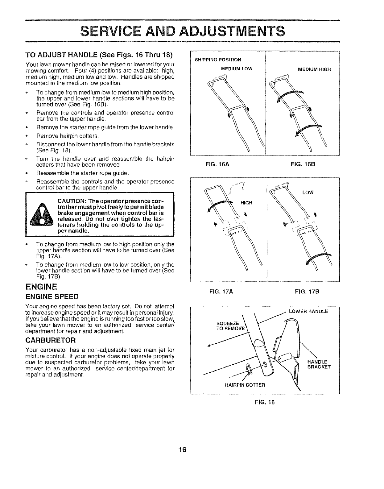
TO ADJUST HANDLE (See Figs. 16 Thru 18)
Your lawn mower handle can be raised or lowered for your
mowing comfortr Four (4) positions are available: high,
medium high, medium low and low HandIes are shipped
mounted in tile medium Iow position.
,, To change from medium low to medium high position,
the upper and lower handle sections will have to be
turned over (See Fig. 16B).
- Remove the controis and operator presence control
bar from the upper handle
* Remove the starter rope guide from the lower handle
', Remove hairpin cotters
- Disconnect the lower handle from the handle brackets
(See Fig 18).
" Turn the handle over and reassemble the hairpin
cotters that have been removed
,, Reassemble the starter rope guide.
= Reassemble the controls and the operator presence
control bar to the upper handle.
CAUTION: The operator presence con-
trol bar must pivot freely to permit blade
brake engagement when control bar is
released. Do not over tighten the fas-
teners holding the controls to the up-
per handle.
, To change from medium tow to high position only the
upper handle section wilt have to be turned over (See
Fig. 17A)
- To change from medium low to low position, only the
lower handle section will have to be turned over (See
Fig. 17B)
ENGINE
ENGINE SPEED
Your engine speed has been factory set. Do not attempt
to increase engine speed or itmay result in personaJinjury.
If you believe that the engine is running toofast or toostow,
take your tawn mower to an authorized service center!
department for repair and adjustment
CARBURETOR
Your carburetor has a non-adjustable fixed main jet for
mixture control. If your engine does not operate properly
due to suspected carburetor problems, take your lawn
mower to an authorized service center/department for
repair and adjustment
SHtPPING POSITION
MEDIUM LOW
MEDIUM HIGH
FtGo 16A FIG. 16B
_\ HIGH
FIG. 17A FIG. 17B
LOWERHANDLE
SQUEEZE
TOREUOVE\
HANDLE
BRACKET
HAIRPIN COTTER
FIG. 18
t 6
STORAGE
ii
Immediately prepare your lawn mower for storage at the
end of the season or if the unit will not be used for 30 days
or more
LAWN MOWER
When lawn moweris to be stored fore period of time, clean
it thoroughly, remove all did, grease, leaves, etc Store in
a clean, dry area.
- Clean entire lawn mower (See "CLEANING" in the
Customer Responsibilities section of this manual).
• Lubricate as shown {n the Customer Responsibilities
section of this manual
,, Be sure that all nuts, bolts, screws, and pins are
securely tastened Inspect moving parts for damage,
breakage and wear'. Replace if necessar'yo
• Touch up el! rusted or chipped paint surfaces; sand
lightly before painting.
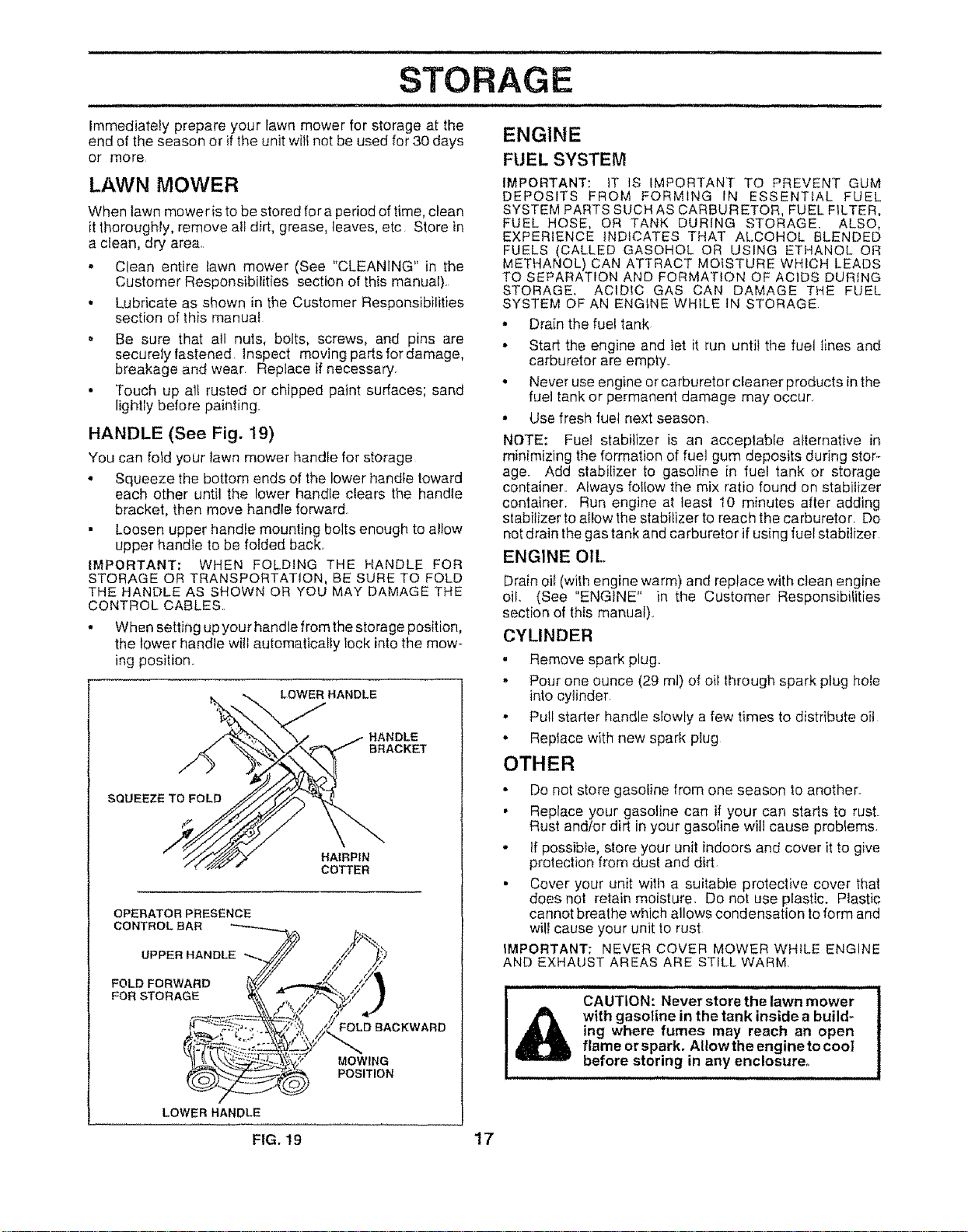
HANDLE (See Fig. 19)
You can foid your lawn mower handle for storage
° Squeeze the bottom ends of the lower handle toward
each other until the lower handle clears the handle
bracket, then move handle forward
• Loosen upper handle mounting bolts enough to allow
upper handle to be folded back,,
IMPORTANT; WHEN FOLDING THE HANDLE FOR
STORAGE OR TRANSPORTATION, BE SURE TO FOLD
THE HANDLE AS SHOWN OR YOU MAY DAMAGE THE
CONTROL CABLES.
• When setting upyour handle from the storage position,
the tower handle will automatically lock into the mow-
ing position,,
LOWER HANDLE
HANDLE
BRACKET
SQUEEZE TO FOLD
HAIRPIN
COTTER
OPERATOR PRESENCE
CONTROL BAR "_.-,--,-.,.._.
UPPER HANDLE _iS
LOWER HANDLE
/Y /!t
/y'
/_YFOLDBACKWARD
MOWING
>_ POSITION
ENGINE
FUEL SYSTEM
iMPORTANT: iT IS IMPORTANT TO PREVENT GUM
DEPOSITS FROM FORMING IN ESSENTIAL FUEL
SYSTEM PARTS SUCHAS CARBURETOR, FUEL FILTER,
FUEL HOSE, OR TANK DURING STORAGE. ALSO,
EXPERIENCE INDICATES THAT ALCOHOL BLENDED
FUELS (CALLED GASOHOL OR USING ETHANOL OR
METHANOL) CAN ATTRACT MOISTURE WHICH LEADS
TO SEPARATION AND FORMATION OF ACIDS DURING
STORAGE, ACIDIC GAS CAN DAMAGE THE FUEL
SYSTEM OF AN ENGINE WHILE tN STORAGE
• Drain the fuel tank
• Start the engine and let it run until the fuel lines and
carburetor are empty,
• Never use engine orcarburetor cleaner products in the
fuel tank or permanent damage may occur,
• Use fresh fuel next season,
NOTE: Fuel stabilizer is an acceptable alternative in
minimizing the formation of fuel gum deposits during stor-
age. Add stabilizer to gasoline in fuel tank or storage
container, Always follow the mix ratio found on stabilizer
container. Run engine at least t0 minutes after adding
stabilizer to allow the stabilizer to reach the carburetor. Do
not drain thegas tank and carburetor if using fuel stabilizer
ENGINE OIL
Drain oil (with engine warm) and replace with clean engine
oil, (See "ENGINE" in the Customer Responsibilities
section of this manual).
CYLINDER
, Remove spark plug
, Pour one ounce (29 ml) of oil lhrough spark plug hole
into cylinder
- Pull stader handle slowly a few times to distribute oil
o Replace with new spark ptug
OTHER
• Do not store gasoline from one season to another.
• Replace your gasoline can if your can starts to rust
Rust andfor dirt in your gasoline will cause problems.
" If possible, store your unit indoors and cover it to give
protection from dust and di..'t
• Cover your unit with a suitable protective cover that
does not retain moisture. Do not use plastic. Plastic
cannot brealhe which allows condensation to form and
witl cause your unit to rust
IMPORTANT: NEVER COVER MOWER WHILE ENGINE
AND EXHAUST AREAS ARE STILL WARM.
CAUTION: Never store the lawn mower
with gasoline in the tank inside a build-
ing where fumes may reach an open
flame or spark. AIIowthe engineto cool
before storing in any enclosure.
FIG. 19 17
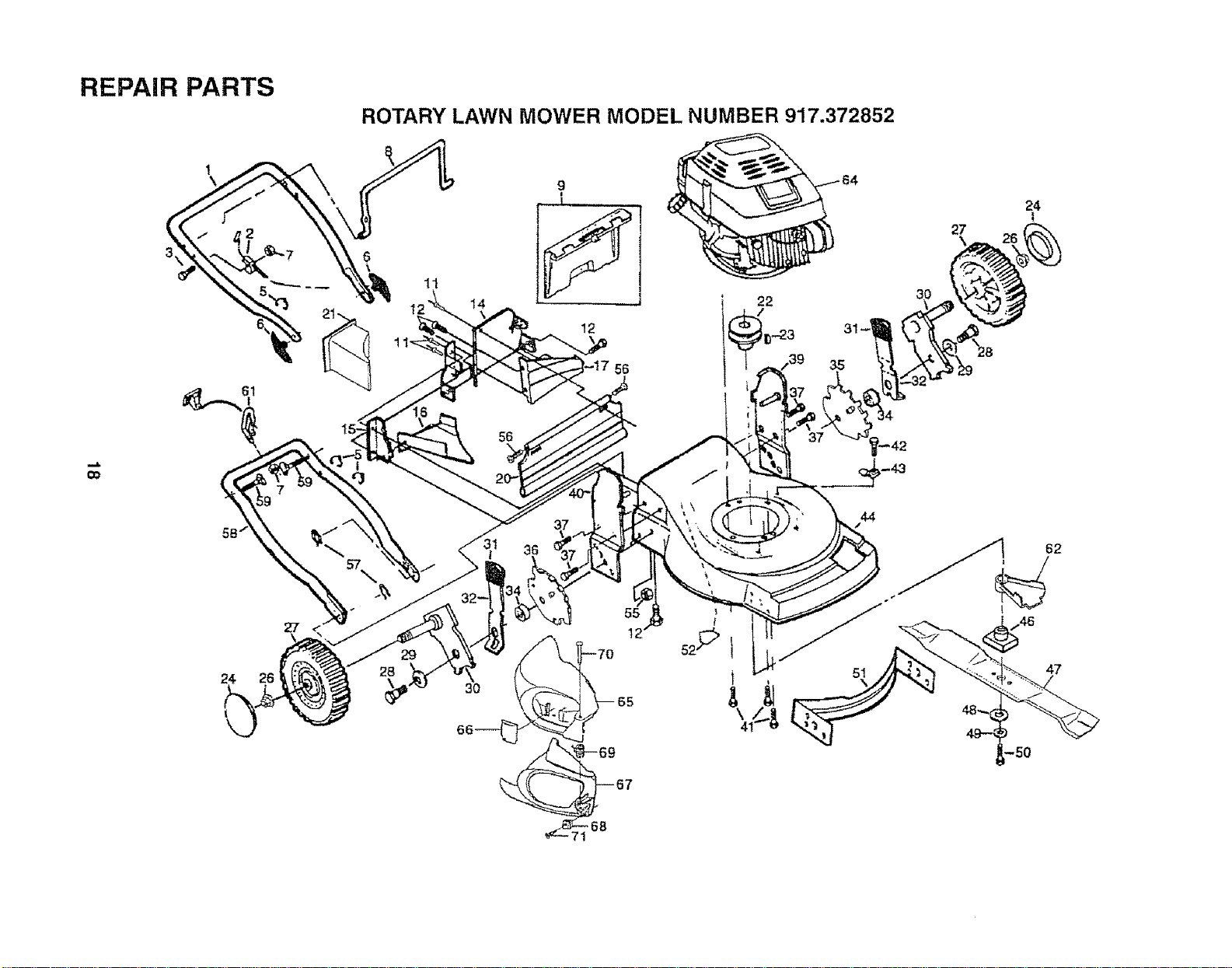
REPAIR PARTS
ROTARY LAWN MOWER MODEL NUMBER 917.372852
24
27
28
11
3O
56
9
12
56
55
12'
22
51
\
24
27
47
68
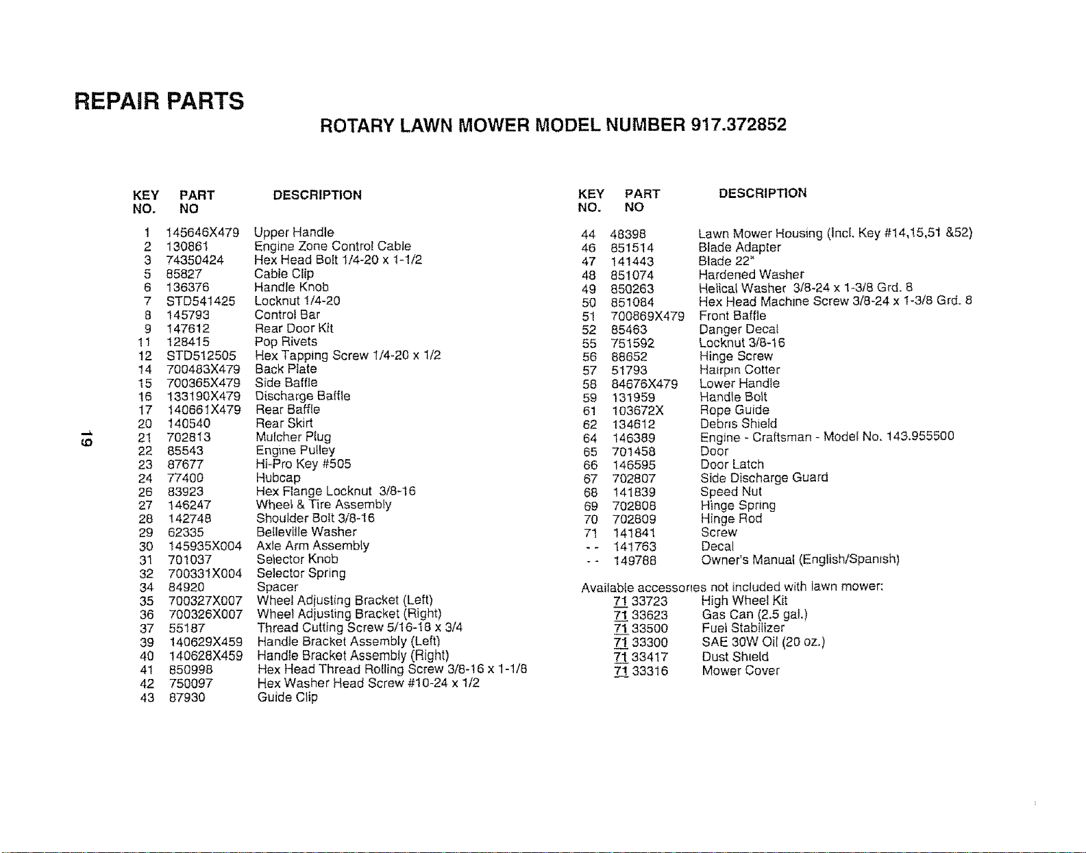
REPAIR PARTS
ROTARY LAWN MOWER MODEL NUMBER 917.372852
LO
KEY PART
NO. NO
1 145646X479
2 130861
3 74350424
5 85827
8 136376
7 STD541425
8 145793
9 147612
11 128415
12 STD512505
14 700483X479
15 700365X479
16 133!90X479
17 14066IX479
20 140540
2! 702813
22 85543
23 87677
24 77400
26 83923
27 146247
28 142748
29 62335
30 145935X004
31 701037
32 700331X004
34 84920
35 700327X007
36 700326X007
37 55187
39 140629X459
40 !40628X459
41 850998
42 750097
43 87930
DESCRIPTION
Upper Handle
Engine Zone Control Cable
Hex Head Bolt 1/4-20 x 1-1/2
Cabte Clip
Handle Knob
Locknut !/4-20
Control Bar
Rear Door Kk
Pop Rivets
Hex Tapping Screw 1/4-20 x t/2
Back Plate
Side Baffle
Discharge Baffle
Rear Baffle
Rear Skirt
Mulcher Plug
Engine Pulley
Hi-Pro Key #505
Hubcap
Hex F!ange Locknut 3/8-16
Whee_ & Tire Assembly
Shoulder Bolt 3/8-16
Betleville Washer
Axle Arm Assembly
Selector Knob
Selector Spring
Spacer
Wheel Adiusting Bracket (Left)
Wheel Adiusting Bracket (Right)
Thread Cutting Screw 5/16-18 x 3/4
Handle Bracket Assembly (Left)
Handle Bracket Assembly (Right)
Hex Head Thread Ro!ling Screw 3/8-16 x 1-1/8
Hex Washer Head Screw #10-24 x 1/2
Guide Clip
KEY PART DESCRIPTION
NO. NO
44 48398 Lawn Mower Housing (lncl, Key #14,15,51 &52)
46 851514 Blade Adapter
47 141443 Blade 22"
48 851074 Hardened Washer
49 850263 Hetical Washer 3/8-24 x 1-3/8 Grd. 8
50 851084 Hex Head Machine Screw 3/8-24 x I-3/8 Grd. 8
51 700869X479 Front Baffle
52 85463 Danger Decat
55 751592 Locknut 3/8-16
56 88652 Hinge Screw
57 51793 Hairpin Cotter
58 84676X479 Lower Handle
59 131959 Handle Bo_t
61 103672X Rope Guide
62 134612 Debns Shield
64 146389 Engine - Craftsman - Model No. 143,955500
65 701458 Door
66 146595 Door Latch
67 702807 Side Discharge Guard
68 141839 Speed Nut
69 702808 Hinge Spring
70 702809 Hinge Rod
71 141841 Screw
- _ 141763 Decal
- - 149788 Owner's Manual (English!Spanish)
Available accessories not included with iawn mower:
7! 33723 High Wheel Kit
71 33623 Gas Can (2.5 gal.)
71 33500 Fuel Stabilizer
7-1 33300 SAE 30W Oil (20 oz,)
71 33417 Dust Shield
7_..11.33316 Mower Cover
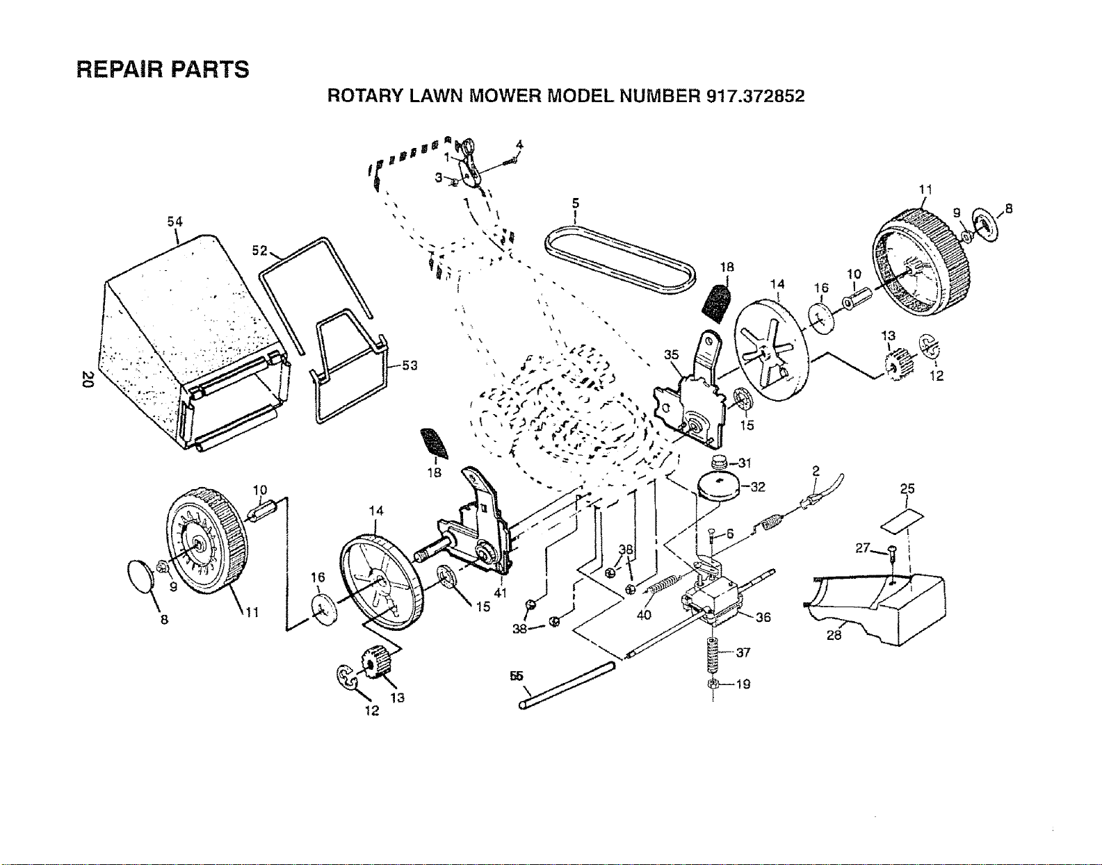
REPAIR PARTS
ROTARY LAWN MOWER MODEL NUMBER 917.372852
54
10
11
./
15
13
12
I
-37
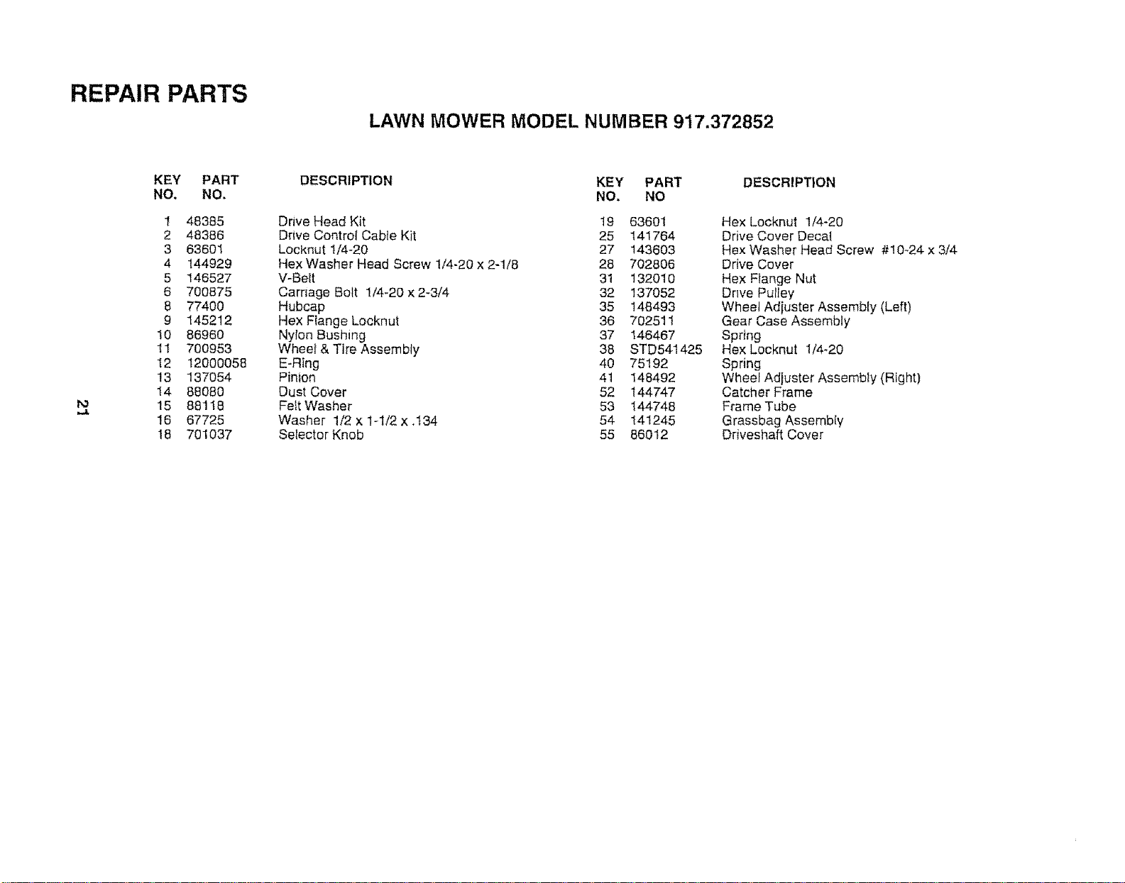
REPAIR PARTS
LAWN MOWER MODEL NUMBER 917.372852
KEY PART
NO. NO.
t 48385
2 48386
3 63601
4 144929
5 146527
6 700875
8 77400
9 145212
10 86960
11 700953
12 12000058
13 137054
14 88080
15 88118
16 67725
18 701037
DESCRIPTION
Drive Head Kit
Drive Control Cable Kit
Locknut1/4-20
Hex Washer Head Screw 1/4-20 x 2-1/8
WBe_t
Carriage Bott 1/4-20 x 2-3/4
Hubcap
Hex Flange Locknut
Nylon Bushing
Wheel & Tire Assembly
E-Ring
Pinion
Dust Cover
Fett Washer
Washer 1/2 x 1-1/2 x .134
Selector Knob
KEY PART
NO. NO
19 63601
25 141764
27 143603
28 702806
31 132010
32 137052
35 148493
36 702511
37 146467
38 STD541425
40 75192
41 148492
52 144747
53 144748
54 141245
55 86012
DESCRIPTION
Hex Locknut 1/4-20
Drive Cover Decat
Hex Washer Head Screw #10-24 x 3/4
Drive Cover
Hex Flange Nut
Drwe Putley
Wheel Adiuster Assembly (Left)
Gear Case Assembly
Spring
Hex Locknut 1/4-20
Spring
Wheel Adiuster Assembly (Right)
Catcher Frame
Frame Tube
Grassbag Assembly
Driveshaft Cover
REPAIR PARTS
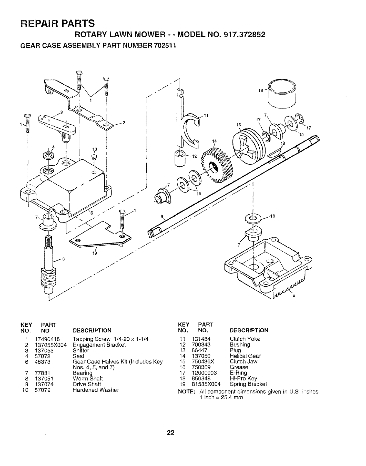
ROTARY LAWN MOWER - - MODEL NO. 917.372852
GEAR CASE ASSEMBLY PART NUMBER 70251 1
13
19
j//'_/
,..f /
/
14
17
17
10
KEY
NO,
1
2
3
4
6
7
8
9
10
PART
NO,
17490416
137055X004
137053
57072
48373
77881
137051
137074
57079
DESCRIPTION
Tapping Screw 1/4-20 x 1-t/4
Engagement Bracket
Shifter
Seal
Gear Case Halves Kit (Includes Key
Nos_4, 5, and 7)
Bearing
Worm Shaft
Drive Shaft
Hardened Washer
KEY PART
NO. NO. DESCRIPTION
11 131484
12 700343
13 86447
14 137050
15 750436X
16 750369
17 12000003
18 850848
19 81585X004
NOTE;
Clutch Yoke
Bushing
Plug
Helical Gear
Clutch Jaw
Grease
E-Ring
Hi-Pro Key
Spring Bracket
Ail component dimensions given in U.S. inches,
1 inch = 25,4 mm
22
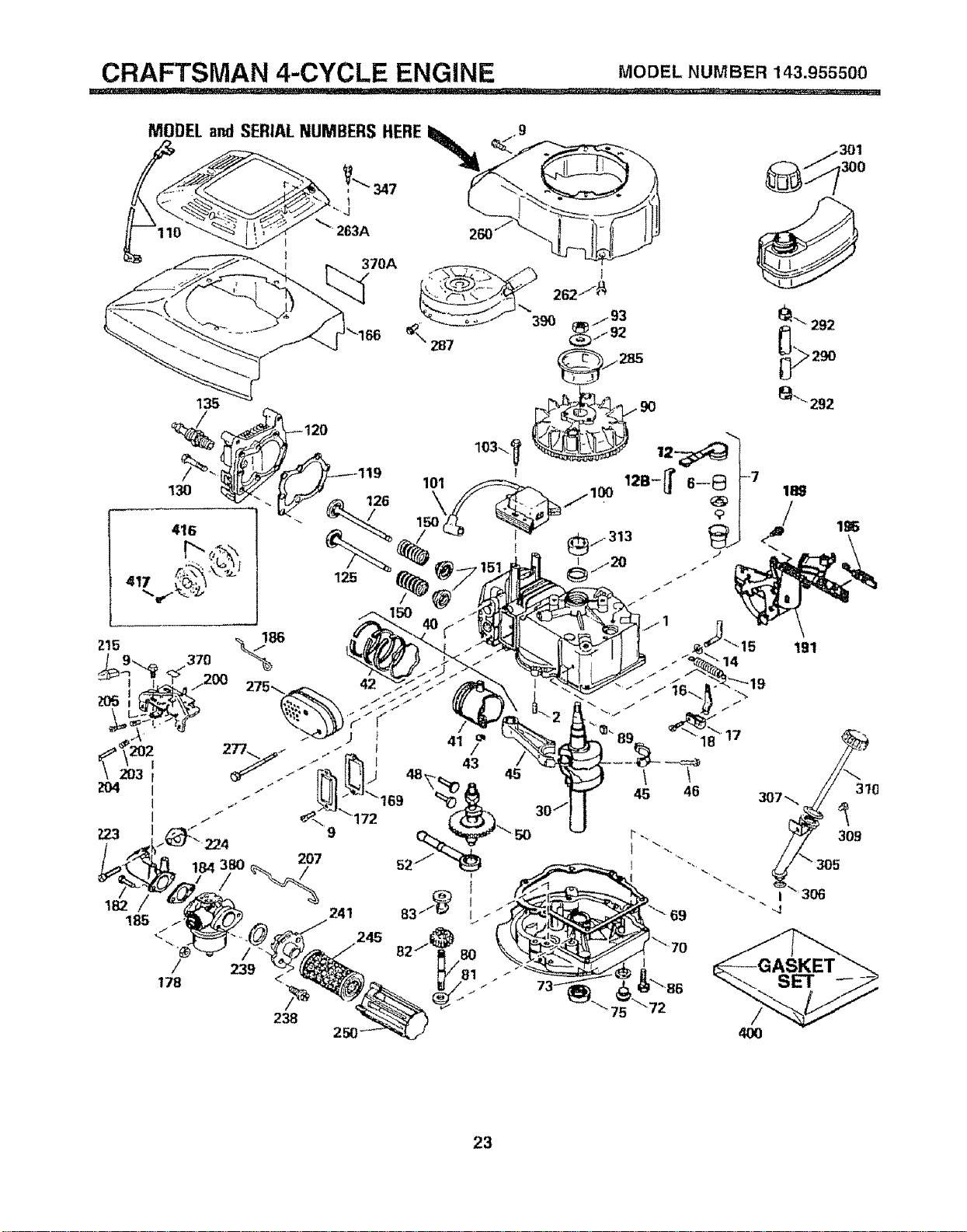
CRAFTSMAN 4-CYCLE ENGINE MODEL NUMBER 143.955500
MODEL andSERIALNUMBERS HERE
+_ 263A
301
/
23
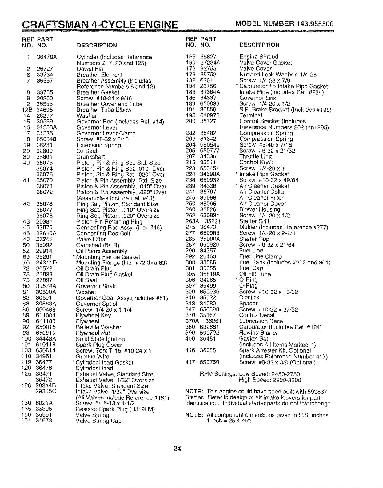
CRAFTSMAN 4.-CYCLE ENGINE MODELNUMBER143.955500
REF PART REF PART
NO. NO. DESCRIPTION NO, NO, DESCRIPTION
1 36478A
2 26727
6 33734
7 36557
8 33735
9 30200
12 36558
12B 34695
14 28277
't5 30589
16 31383A
17 31335
18 650548
19 36281
20 32600
30 35801
40 36073
36074
36075
41 36070
36071
36072
42 36076
36077
36078
43 20381
45 32875
46 32610A
48 27241
50 35992
52 29914
69 35261
70 34311D
72 30572
73 28833
75 27897
80 30574A
81 30590A
82 30591
83 30588A
86 650488
89 611004
90 611109
92 650815
93 650816
100 34443A
101 610118
103 650814
110 34961
119 36477
120 36476
125 36471
36472
126 293t4B
29315C
130 6021A
135 35395
150 35991
t51 31673
Cylinder (Includes Reference 166 35827
Numbers 2, 7, 20 and 125) 169 27234A
Dowel Pin 172 32755
Breather Element t78 29752
Breather Assembly (Includes 182 6201
Reference Numbers 6 and 12) 184. 26756
* Breather Gasket I85 31384A
Screw #10-24 x 9/!6 186 34337
Breather Cover and Tube 189 650839
Breather Tube Elbow 191 36559
Washer 195 610973
Governor Rod (Includes Ref #14) 200 35727
Governor Lever
Governor Lever Ctamp 202 36482
Screw #8-32 x 5/16 203 31342
Extension Spring 204 650549
Oii Seal 205 650777
Crankshaft 207 34336
Piston, Pin & Ring Set, Std. Size 215 35511
Piston, Pin & Ring Set, 010" Over 223 650451
Piston, Pin & Ring Set, .020" Over 224 34690A
Piston & Pin Assembly, Std. Size 238 650932
Piston & Pin Assembly, .010" Over 239 34338
Piston & Pin Assembly, .020" Over 241 35797
(Assemblies Include ReL #43) 245 35066
Ring Set, Piston, Standard Size 250 35065
Ring Set, Piston, 010" Oversize 260 35826
Ring Set, Piston, 020" Oversize 262 650831
Piston Pin Retaining Ring 263A 35821
Connecting Rod Assy (incl #46) 275 364.73
Connecting Rod Boll 277 650988
Valve Lifter 285 35000A
Camshaft (BCR) 287 650926
Oil Pump Assembly 290 34357
* Mounting Flange Gasket 292 26460
Mounting Flange (tncl #72 thru 83) 300 35586
Oil Drain Plug 301 35355
Oil Drain PIug Gasket 305 35819A
Oil Seal 306 34265
Governor Shaft 307 35499
Washer 309 650936
Governor Gear Assy.(lncludes #81) 310 35822
Governor Spool 313 34080
Screw 1/4-20 x 1-114 347 650898
Flywheel Key 370 35167
Flywheel 370A 36261
Betteviile Washer 380 632681
Ftywhee_ Nut 390 590702
Solid State ignition 400 36481
Spark Plug Cover
Screw, Torx T-15 #10-24 x 1 416 36085
G round Wire
"Cylinder Head Gasket 417 650760
Cylinder Head
Exhaust Valve, Standard Size
Exhaust Valve, 1/32" Oversize
Intake Valve, Standard Size
Intake Valve, 1/32" Oversize
(All Valves include Reference #15t)
Screw 5/I6-18 x 1-1/2
Resistor Spark Plug (RJ19LM)
Valve Spring
Valve Spring Cap
Engine Shroud
"Valve Cover Gasket
Valve Cover
Nut and Lock Washer 1/4-28
Screw 1/4-28 x 7/8
* Carburetor To Intake Pipe Gasket
Intake Pipe (Includes Ref #224)
Governor Link
Screw 1/4-20 x 1/2
SE Brake Bracket (includes #195)
Terminal
Control Bracket (includes
Reference Numbers 202 thru 205)
Compression Spring
Compression Spring
Screw #5-40 x 7/16
Screw #6_32 x 21/32
Throttle Link
Control Knob
Screw 1/4.-20 x 1
" Intake Pipe Gasket
Screw #10..32 x 49/64
* Air Cleaner Gasket
Air Cleaner Collar
Air Cleaner Filter
Air Cleaner Cover
Blower Housing
Screw 1/4-20 x 1/2
Starter Grill
Muffler (includes Reference #277)
Screw 1/4-20 x 2-t/4
Siader Cup
Screw #8-32 x 21/64
Fuel Line
Fuel Line Clamp
Fuel Tank (Includes #292 and 301 )
Fuel Cap
Oil Frtl Tube
* O-Ring
O-Ring
Screw #10-32 x 13/32
Dipstick
Spacer
Screw #10-32 x 27/32
Control Decal
Lubrication Decal
Carburetor (includes Ref #184)
Rewind Starter
Gasket Set
(includes All Items Marked *)
Spark Arrester Kit, Optional
(includes Reference Number 417)
Screw #8-32 x 318 (Optiona!)
RPM Settings: Low Speed: 2450-2750
High Speed: 2900_3200
NOTE: This engine could have been built with 590637
Starter, Refer to design of air intake louvers for part
identification Individual starter parts do not interchange.
NOTE: All component dimensions given in U.S. inches
1 inch = 25.4 mm
24
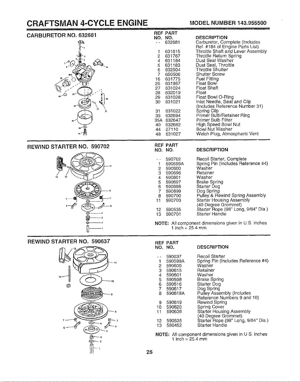
CRAFTSMAN 4-CYCLE ENGINE
:7 I! I _J, r i=ii" ,,, ......... @ ........ IIII
CARBURETOR NO. 63268'1
/{ 3 "
REF PART
NO,, NO.
- - 632681
t 631615
2 631767
4 631184
5 631183
6 632504
7 650506
16 631775
25 631867
27 631024
28 632019
29 631028
30 631021
3l 631022
35 632694
35A 832647
40 632682
44 2711O
48 631027
MODEL NUMBER 143.955500
DESCRIPTION
Carburetor, Complete (Includes
ReL #184 of Engine Parts List)
Throttle Shaft and Lever Assembly
Throttle Return Spring
Dust Seal Washer
Dust Seal, Throttle
Throttle Shutter
Shutter Screw
Fuel Fitting
Float Bowl
Float Shaft
Float
Float Bowl Q-Ring
Inlet Needle, Seat and Clip
(includes Reference Number 31)
Spring Clip
Primer Bulb/Retainer Ring
Primer Bulb Filter
High Speed Bowl Nut
Bowl Nut Washer
Welch Plug, Atmospheric Vent
REWIND STARTER NO. 590702
REF PART
NO. NO DESCRIPTION
_- 590702
1 590599A
2 590600
3 590696
4 590601
5 590697
6 590698
7 590699
8 590700
11 590703
12 590535
13 590701
Recoil Starter, Complete
Spring Pin (Includes Reference #4)
Washer
Retainer
Washer
Brake Spring
Starter Dog
Dog Spring
Pulley & Rewind Spring Assembly
Starter Housing Assembly
(40 Degree Grommet)
Starter Rope (98" Long, 9t64" Dia)
Starter Handle
REWIND STARTER NO. 590637
NOTE: Al! component dimensions given in U,S, inches
i inch = 254 mm
,,,, , ,,,,, ,,,,,,i,,,,,,, ,i,,,,
REF PART
NO. NO. DESCRIPTION
-- 590637 Recoil Starter
1 590599A Spring Pin (Includes Reference #4)
2 590600 Washer
3 590615 Retainer
4 590601 Washer
5 590598 Brake Spring
6 590616 Stader Dog
7 590617 Dog Spring
8 590618A Puttey Assembly (Includes
Reference Numbers 9 and 10)
9 590619 Rewind Spring
I0 590620 Spring Cover
11 590638 Starter Housing Assembly
(40 Degree Grommet)
12 590535 Starter Rope (98' Long, 9/64" Die,)
13 590452 Starter Handle
NOTE: All component dimensions given in US, inches
1 inch = 254 mm
25

SERVICE NOTES
26
,,,.,i,,,i,,.l_t J tt i U_l ,, iii nlu, ii
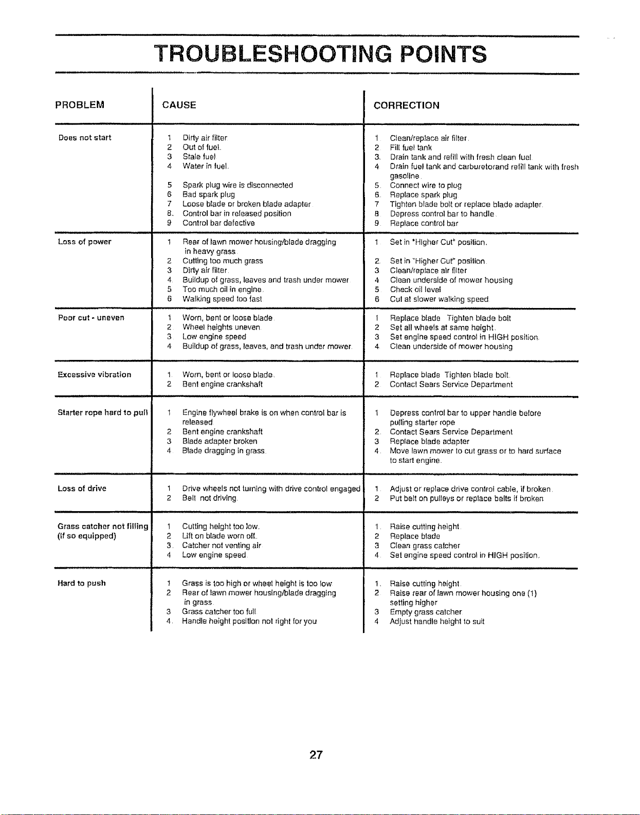
TROUBLESHOOTING POINTS
m i i1,,
PROBLEM
Does not start
Loss of power
Poor cut - uneven
Excessive vibration
Starter rope hard to pug
Lose of drive
in i , 1, iiiii
Grass catcher not tilting
(ff so equipped)
Hard to push
CAUSE
1 Dirty air filter
2 Out of fuel
3 Stale fueJ
4 Water in fuel
5 Spark plug wire is disconnected
6 Bad spark plug
7 Loose btade or broken blade adapter
8. Control bar in released position
g Control bar defective
t Rear of lawn mower housing/blade dragging
in heavy grass
2 Catting toomuch grass
3 Dirty air tilter
4 Buildup of grass, leaves and trash under mower
5 Too much oil inengine
6 Watklng speed too fast
t Worn, bent or loose blade
2 Whoa! heights uneven
3 Low engine speed
4 Buildup o{ grass, leaves, and trash under mower
t Worn, bent or loose blade,
2 Bent engine crankshaft
1 Engine flywheel brake ison when control bar is
released
2 Bent engine crankshaft
3 Blade adapter broken
4 Blade dragging in grass
,i, ................
Drive wheets not turning with drive control engaged
CORRECTION
1 Cfean/rep]ace air filter,
2 Fill fuel tank
3 Drain tank and refill with fresh clean fuel
4 Drain fuel tank and ca_buretorand re{ill tank with fresh
gasoline
5 Connect wire to plug
6 Replace spark plug
7 Tighten blade belt or replace blade adapter
B Depress control bar to handle
9 Replace control bar
1 Set in "Higher Cut" position
2 Set in_Higher Cut" posilion
3 Clean/repJaee alr filter
4 Clean underside of mower housing
5 Check oillevet
6 Cut at slower walking speed
t Replace blade Tighten blade bolt
2 Set all wheels at same height,
3 Set engine speed eontroiin HIGH position
4 Clean underside of mower housing
I Replace blade Tighten blade bolt
2 Contact Sears Service Department
t Depress control bar to upper handle betore
palling starter rope
2 Contact Sears Service Department
3 Rap{ace blade adapter
4 Move lawn mower to cut grass or to hard surface
to star! engine
1 Adjust or replace drive conlrot cable, if broken
BaH not drMng
n ii i
1 Cutting height too law,
2 Lift on btade worn off.,
3 Catcher not venting air
4 Low engine speed
1 Grass is too high or wheel height is too Iow
2 Rear at lawn mower housing/blade dragging
ingrass
3 Grass caleher too full
4 Handle height position not right for you
2 Put belt on pulleys or replace belts if broken
1 Raise cutting height
2 Replace blade
3 Clean grass catcher
4 Set engine speed control in HIGH position,
I, Raise cutting height
2 Raise rear of lawn mower housing one (1)
setting higher
3 Empty grass catcher
4 Adjust handle height to suit
27
OWNER'S
MANUAL
MODEL NO.
917.372852
IF YOU NEED
REPAIR SERVICE
OR PARTS:
FOR REPAIR SERVICE, CALL
THIS TOLL FREE NUMBER:
1-800-4-REPAIR
(1-B00-473_7247)
FOR REPLACEMENT PARTS
INFORMATION AND
ORDERING, CALL THIS
TOLL FREE NUMBER:
1-800-FON-PART
(1-800-366_7278)
®
5.5 HORSEPOWER
22" 3 in ONE Convertible
POWER PROPELLED
ROTARY LAWN MOWER
Each tawn mower has its own model number, Each en-
gine has its own modei number.
The model number for your lawn mower will be found on a
decal attached to the rear of the lawn mower housing.
The model number for your engine will be found on the
blower housing of the engine.
All parts listed herein may be ordered from any Sears,
Roebuck and Co. Service Center/Department and most
Retail Stores
WHEN ORDERING REPAIR PARTS, ALWAYS GIVE THE
FOLLOWING INFORMATION:
° PRODUCT _LAWN MOWER
a MODEL NUMBER - 917.372852
- ENGINE MODEL NO, - 143.955500
o PART NUMBER
• PART DESCRIPTION
Your Sears merchandise has added value when you
consider Sears has service units nationwide staffed with
Sears trained technicians .... professional technicians
specifically trained to insure that we meet our pledge to
you, we service what we sell,
28