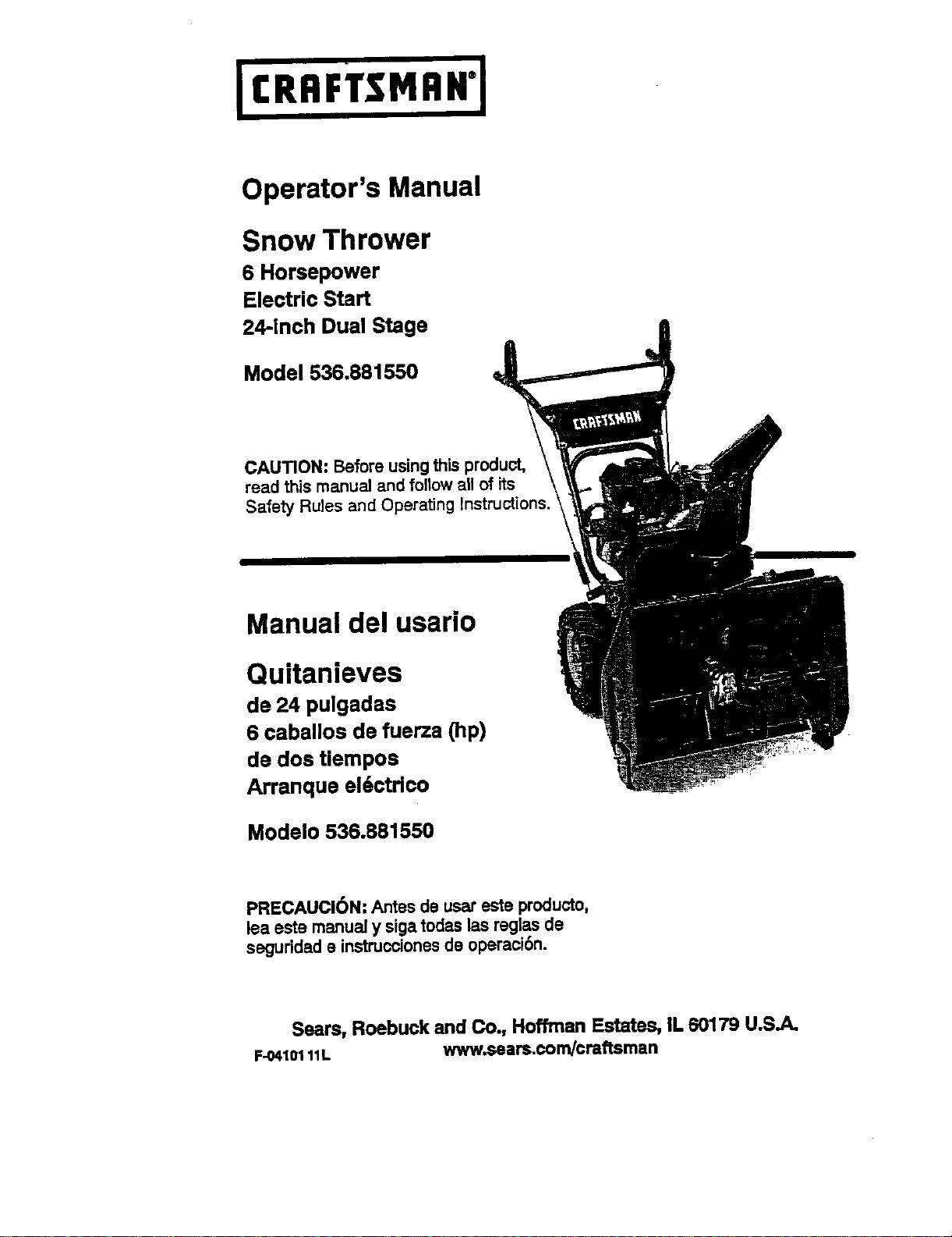
Operator's Manual
Snow Thrower
6 Horsepower
Electric Start
24-inch Dual Stags
Model 536.881550
CAUTION: Before using this product,
read this manual and foflow all of its
Safety Rules and Operating Instructions.
Manual del usario
Quitanieves
de 24 pulgadas
6 caballos de fuerza (hp)
de dos Uempos
Arranque el6ctdco
Modelo 536.881550
PRECAUCI6N: Antes de usar este producto,
lea este manual y siga todas las reglas de
seguddad e instruccionesde operaci6n.
Sears, Roebuck and Co., Hoffrnan Estates, IL 60179 U.S.A.
F-04101 11L www.sean;.com/craftsman
WARRANTY STATEMENT ......
SAFETY RULES . ..
*.....lw**l •
INTERNATIONAL SYMBOLS ....
ASSEMBLY ...................
OPERATION ..................
MAINTENANCE ...............
SERVICE AND ADJUSTMENT ..
2 STORAGE .................... 33
2 TROUBLESHOOTING TABLE . .. 34
4 REPAIR PARTS ............... 38
6 ENGINE REPAIR PARTS ....... 56
11 SPANISH (ESPA_IOL) .......... 63
18 PARTS ORDERING/SERVICE ..
21 BACK COVER
UMITED TWO-YEAR WARRANTY ON CRAFTSMAN SNOW THROWER
For twoyesrs from the date of purchaes, when this Craftsman Seow thrower is malnlalned,
lubricated, and tuned up according to the operating and maintenance Instructions in the
owner's manual, Sears will repair,free of charge, any defect in material orworkmanship.
ff this _an Snow throweris usedfor commercial or rental purposes, this wan'anty ap-
plies for only90 days flora the date of purchase.
This warranty does notcover _ following:
Items whichbecome worn dudngnormaluse, suchas spark plugs,drive baitsand sheer
pins,
Repair necessary because of operator abuse or negligence, includingbent crankshafts
and the failure to maintain the equipment according tothe instructionscontainedin the
owner's manual.
WARRANTY SERVICE IS AVAILABLE BY RETURNING THE CRAFTSMAN SNOW
THROWER TO THE NEAREST SEARS SERVICE CENTER IN THE UNITED STATES.
THIS WARRANTY' APPLIES ONLY WHILE THIS PRODUCT IS IN USE IN THE UNITED
STATES.
This warranty givesyou spectticlegal rights, and you may also have other dghtswhich may
vary fl'om state to stafa.
Sears, Roebuck and Co., D817WA, Hoffman Estates. IL 60179
LooK FOR THIS SYMBOL TO POINT OUT IMPORTANT SAFETY PRECAUTIONS.
IT MEANS- ATTENTIONIII BECOME ALERTI!I YOUR SAFETY IS INVOLVED.
Engine F.x_aust,some of Its constltuent_ and
certain vehlclo components contain or emlt
chemicals known to the State of Califomia to
cause cancer and birth defects or other repro-
ductiveharm.
Battery posts,terminalsand relatedacesssodes
€ontain lead and load compounds, chemicals
known tothe State ofCaliforniatocausecancer
and birth defects or other mproductNe harm.
WASHHANDS AFTER HANDLING.
A WARNING:Always dis€on-
nect the spark plug wire
and placeitwhereitcannot
mako contact with spark plug to
preventaccidental starlingduring:
Preparation,Maintenance,or Stor-
age ofyour snow thrower.
IMPORTANT;. Safety standardsre-
quire operator presence controlsto
minimizethe risk of injury.Yoursnow
throwerisequippedwithsuchcontrols.
Do notattempttodefeatthefunc'donof
the operatorpresencecontrolunderany
circumstances.
F-0410111L 2
TRAINING
1. Readthisoperatingandserviceinstruction
manualcarefully.Be _omu_ly familiar
w_ thecontrolsandtheproperuseofthe
snowthrower.Knowhowtostopthesnow
throweranddL_engagethecontrolsquick-
ly.
2. Neverallowchildrentooperatethesnow
thrower.Neverallowadultstooperatethe
snowthrowerwi_outproperinslnJction.
3. Ksepthe ereaofoperationdeerof allper-
sons,parUauiedysmallchildrenandpets.
4. Exercisecautiontoavoidslippingorfalling
especiallywhenoperatinginreverse.
PREPARATION
1. Thoroughlyinspectthe areawhere
snowthroweristobeusedandremoveell
doorrnt_, sleds, boards, wires, and other
faragnobje s.
2. Disengagealldutcheebeforestartingthe
engine(motor).
3. Do notoperatethe snowthrowerwithout
wearingadequatewinteroutergarments.
Wearfootwearthatwillimprovefootingon
stipperysurtaces.
4. Handlefuel withcare; it is highlyflam-
mable.
a. Usean approvedfuelcontainer.
b. Neverrercovefueltankc,_poraddfual
toa runningengine(motor)orhoten-
gine(motor).
c. Fillfuel tank outdoorswith extreme
care. Neverfillfueltankindoors.
d. Replacefuel capsecurelyandwipeup
spilledfuel.
e. Neverstorefuelor snowthrower with
fuel in the tank inside of a building
wherefumesmayreachanopen11ame
orspark.
f. Checkfuelsupplybeforeeachuse,al-
lowingspaceforexpansionasthehoat
ofthe engine(motor)and/orsuncan
causefueltoexpand.
5. Forallsnowthrowerswithelectricstating
motors use al_a'ic sta_ng extension
cordscert_edCSA/UL Useonlywitha re-
ceptesiethathasbeeninstalledinaccord-
ancewithlocalinspec_onauthorities.
6. let engine(motor)andsnowthrowerad-
justtooutdoortsmperafuresbeforestarting
to cieeranow.
7. Alwayswearsefatyglassesoreyeshields
duringopera_n orwhileperforminganad-
justmentor repairto protecteyes from
foreigndojeststhattraybethrownfromthe
snowthrower.
F-0410111L 3
OPERATION
1. DOnotoperatethissnowthrowerifyouere
takingd"ugsoro_er medica_onwhichcan
causedrowsinessoraffectyourabilityto
operatethissnow_wer.
2. Do not usethe snowthrower if you are
meotellyorphysicallyt_abietooperate
snowthrowersa_ely.
3. Donotputhandsorfaatneeror underro-
toting parts.Keepdeer of the discharge
openingatall times.
4. Exerciseextremecautionwhenoperating
on or crossinggravel drives,walks or
roads.Stay alert for hiddenhazards or
traffic.
5. Afterstrndnga foreignobject,stopthe en-
gine (motor), removethe wire from the
spark plug, thoroughly inspect snow
throwerfor any damage,and repairthe
damage beforerestarl_and opera_g
thesnowthrower.
6. If thesnowthrowershouldstarttovbrate
abnormally,stopthe engine(motor)and
checki'nmadietelyforthecause.VibralJon
isgenerallya wamingoftrouble.
7. Stop the engine (motor)whenever you
leave the operatingposition,beforeun-
clogging_ augerJimpellerhousingordis-
charge chute and when maldng any
repairs,ad}ustmants,or inspections.
8. When cleaning,repairing,or inspecting,
make certainthe auger/a_pellerand
movingpartshavestoppedandallcontrols
aredL_angaged.DisconnectthesparkpSug
wireandImapthewireaway'B'omthesperk
plugto preventaccidentalstarting.
9. Takeallpossibleprece_onswhenleaving
thesnowthrowerunattended.Disengage
auger/impeller,stopengine (motor),
andremovekey.
10. Donotstertorrunangineh sncinsedarea,
evenif doorsor windows are open. Ex-
haustfumes are dangerous(containing
CARBON MONOXIDE, an ODORLESS
andDEADLYGAS).
11. Do not deer snow acrossthe face of
slopes.Exerciseex:l:mmecautionwhen
changhngdirectionon slopes.Do not at-
temptto clearsteepelopes.
12. Neveroperate the snowthrowerwlt_ut
properguards,platesor othersafetypro-
tectlvedevicesin place.
13. Neveroperatethosnowthrowerneeren-
closures,automobiles,windowwells,drop-
offs,andthelikewithoutproperad)ustmant
oflhe snowotschergeangle.Keepchildren
andpetsaway.
14.Donotoverloadthesnowthrowercapaclty
by attem_ngtoclearsnowattsofesta
rate.
15. Never operatethe snowthrower at high
_ansport speeds on slipperysurfaces.
Lookbehindandusecarewhen becking
up.
16. Never directdischargeat bystandersor
allowanyoneinfrontofthesnowthrower.
17. Disengagepowertothecollastor/impeller
whensnowthroweris_'ansportedornotin
USe.
18. Useonlyattachrsentsandaccessoriesap-
provedby the manufectumrof thesnow
thrower (suchas _re chains,electricstart
ecL).
19. Never operate the snowthrowgrwithout
goodvisibilityor light.Alwaysbe sure of
yourfoo_ng and keepa firm holdon the
handles. Wak;neverrun.
20. Do not over-roach.Keep properfoot_
andbalanceat alltimes.
21. Do notattempttousesr=:_thrower on a
roof.
MAINTENANCE AND STORAGE
1. Checkshearbottsandotherbolts at fre-
quent intervalsfor propertightnessto be
surethesnowt_roweris in safeworking
condition.
2. Storethesnowthroworawayfromignition
sourcesor appliancesthat have a pilot
light,suchashotwatorsndspasehestors,
clothesdryers,etc.... Allowtt_ engine
(motor)tocoolbeforestoringinanyenclos-
urB.
3. Always referto operator'sguideins'_uc-
tions for importantdetailsif the snow
thrower is to be storedfor an extended
period.
4. Maintainor replace.safetyand instm_on
labels,asnecessary.
5. Runthesnowthrowerafewminutasafter
throwing snowto preventfreeze-upofthe
auger/impeller.
_ ARNING: This snow throwerIs
for usa on sidewalks, drlvewaye
and otherground levelsurfaces.
Cautionshouldbee_erofsedwhlle usingon
steep sloping surfaces. DO NOT USE
SNOW THROWER ON SURFACESABOVE
GROUND LEVEL such as roofs of reel-
dances, garages, porches or other such
structuresor buildings.
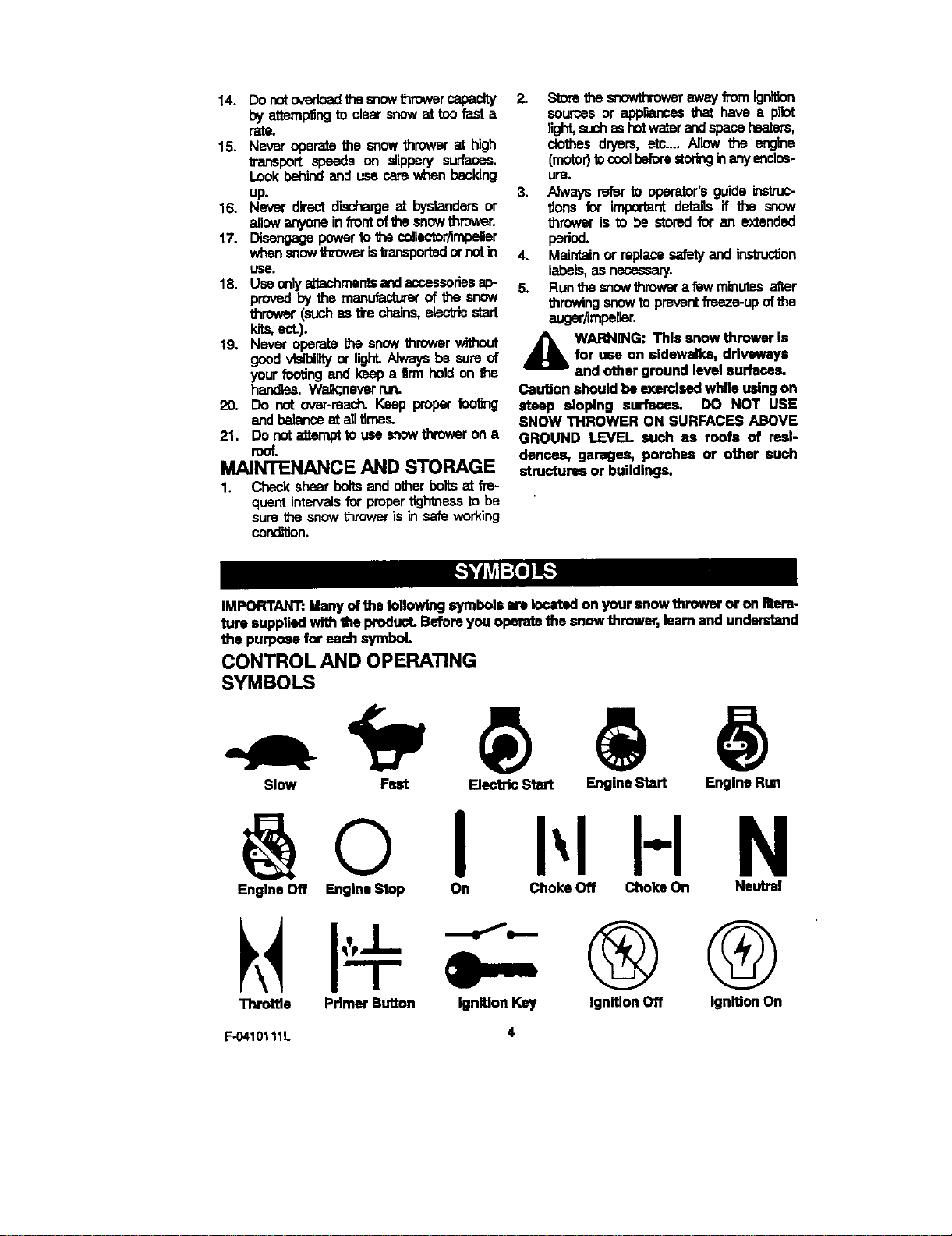
IMPORTANT:Manyof the followltKJsymbolsam Iocstedon your snowthrower or on litera-
ture suppliedwith the product.Bstomyou operatethe snowthrower, learnandunderstand
the purposefor eachsymbol.
CONTROL AND OPERATING
SYMBOLS
Slow Fast ElectricStart EngineStart Engine Run
@0 1 I-IN
Engine Off Engine Stop On Choke Off ChokeOn Neutral
Thrcttlo Primer Button Ignltlon Key
®Q
Ignition Off IgnitionOn
F-O410111L 4
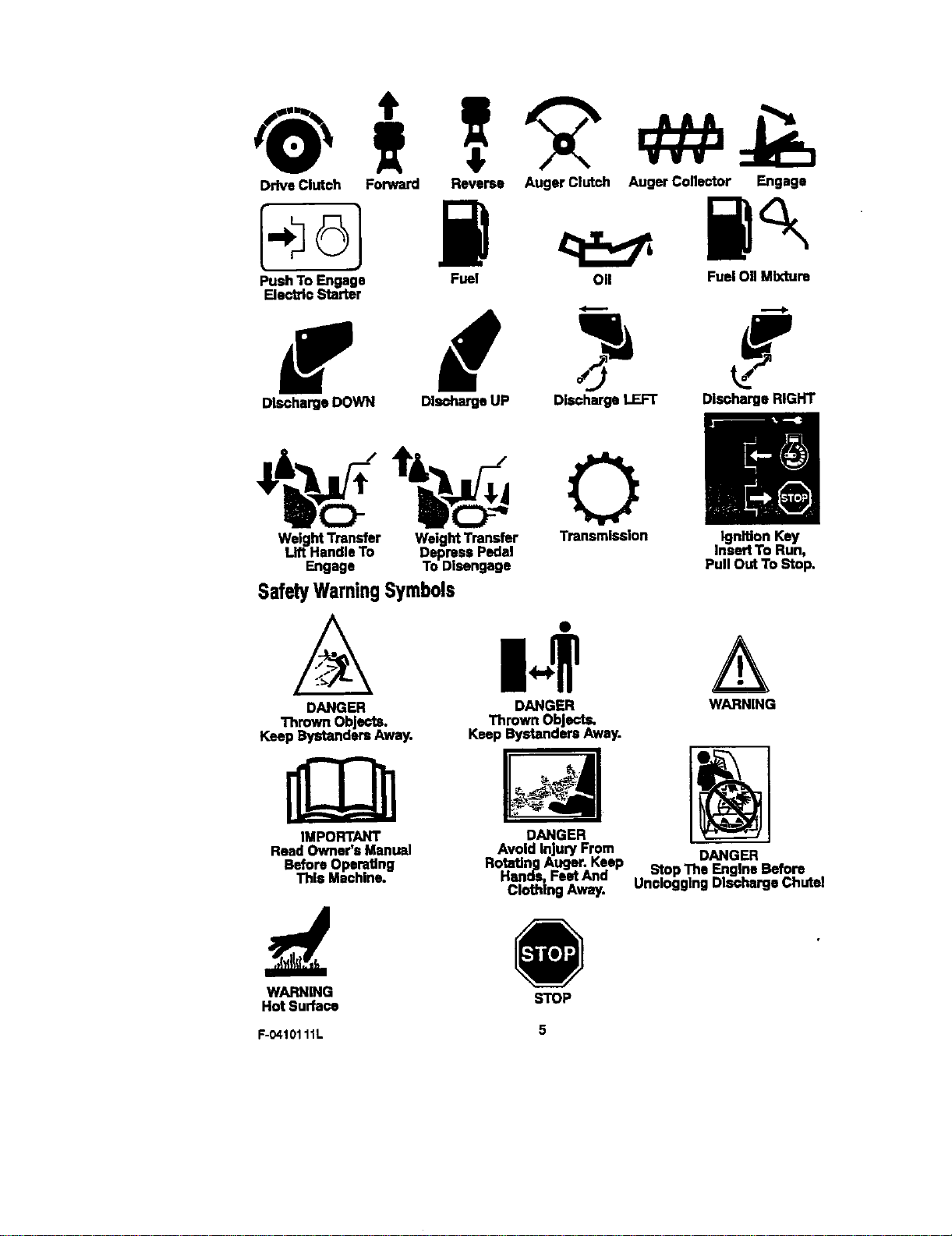
DriveClutch Forward Reverse Auger Clutch Auger Collector Engage
Push To Engage Fuel 011 Fuel 011Mixture
ElectricStarter
DischargeDOWN DischargeUP DischargeLEFT DischargeRIGHT
|JH
WeigM Transfer WeightTransfer Transmission IgnitionKey
Lift HandleTo DepressPedal InsertTo Run,
Engage To Disengage PullOutTo Stop.
SafetyWarningSymbols
DANGER DANGER WARNING
ThrownObjects. Thrown Objects.
Keep BystandersAway. Keep BystandersAway.
IMPORTANT
Read Owner's Manual
BeforeOperedng
ThisMachine.
Avoid InjuryFrom
RotatingAuger. Keep DANGER
Hands, FeetAnd StopThe Engine Before
ClothingAway. UncloggingDlschergeChutal
DANGER
WARNING STOP
Hot Surface
F-0410111L 5
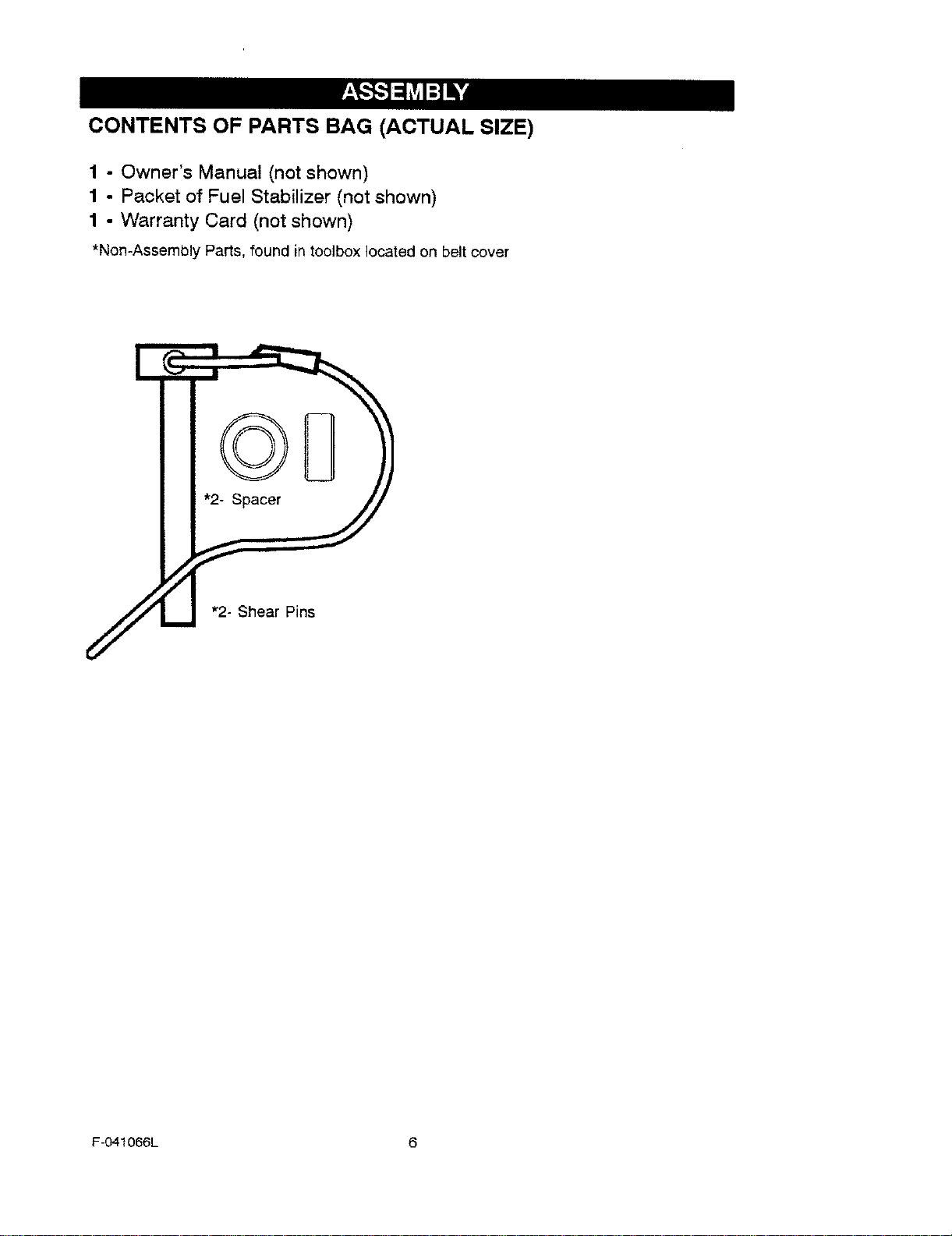
CONTENTS OF PARTS BAG (ACTUAL SIZE)
1 - Owner's Manual (not shown)
1 - Packet of Fuel Stabilizer (not shown)
1 - Warranty Card (not shown)
*Non-Assembly Parts, found in toolbox located on belt cover
F-O41066L 6
,_ WARNING: Always wearsafety glasses or eye shields
while assembling snow
thrower.
TOOLS REQUIRED FOR
ASSEMBLY
1 - Knifeto outcarton
2 - 1/2 inch wrenches
(or adjustable wrenches)
2 - 9/16 inchwrenches
(or adjustable wrenches)
2 - 3/4 inch wrenches
(or adjustable wrenches)
1 - Pliers (to spread cotter pin)
1 - Screwdriver
1 - Measuring tape or ruler
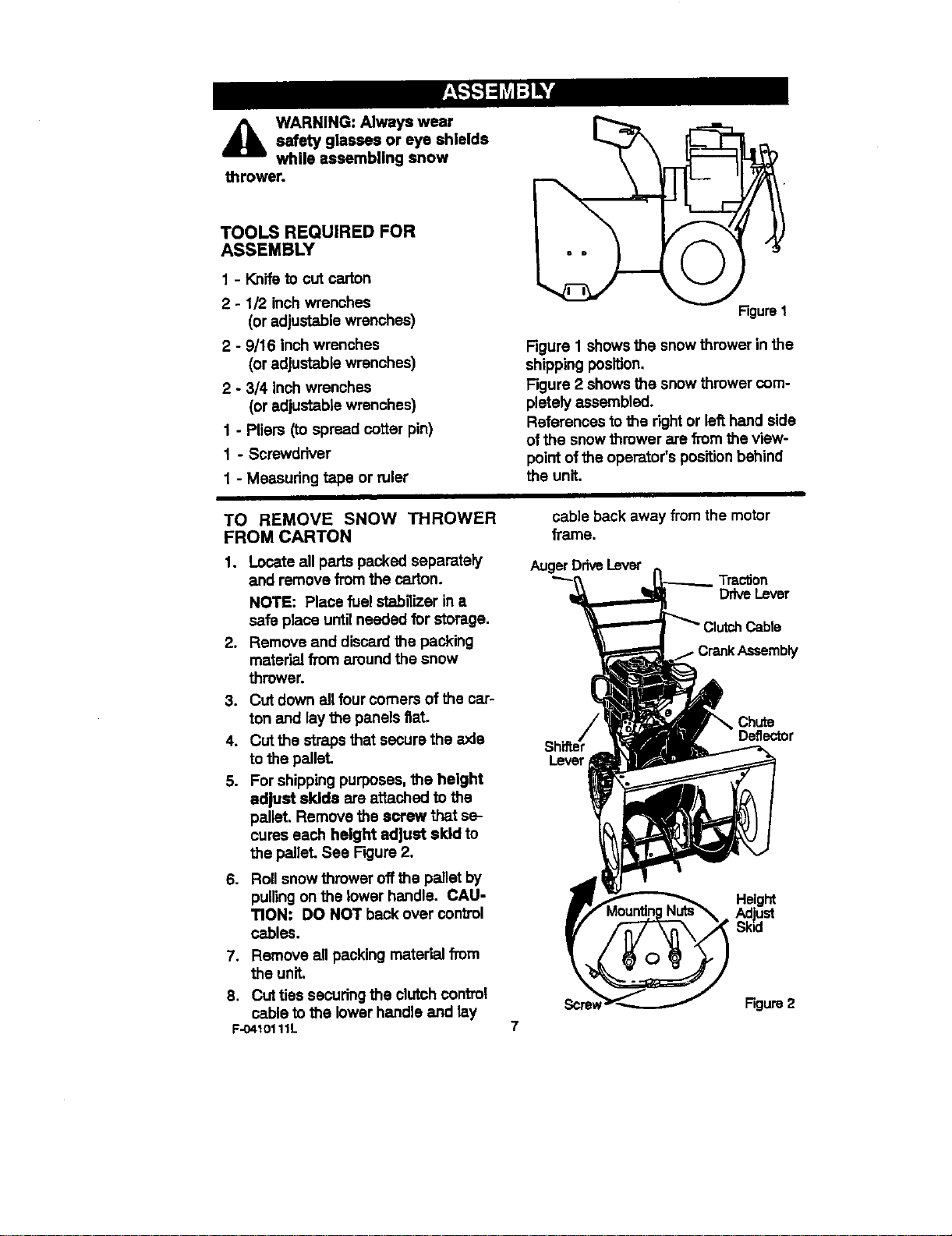
Figure1
Figure 1 shows the snow thrower in the
shipping position.
Figure 2 shows the snow thrower com-
pletely assembled.
References to the right or left hand side
of the snow thrower are from the view-
point ofthe operator's positionbehind
the unit.
TO REMOVE SNOW THROWER
FROM CARTON
1. Locate all parts packed separately
and remove from the carton.
NOTE: Place fuel stabilizer in a
safe place until needed for storage.
2. Remove and discard the packing
material from around the snow
thrower.
3. Cut down all four comers of the car-
ton and laythe panels fiat
4. Cut the straps that secure the axle
to the pallet,
5. For shipping purposes, the height
adjust skids are attached to the
pallet. Remove the screw that se-
cures each height adjust skid to
the pallet. See F'_jure2.
. Roll snow thrower off the pallet by
pullingon the lower handle. CAU-
TION: DO NOT back over contTol
cables.
7. Remove all packing material from
the unit.
8. Cut ties secudng the clutchcontrol
cable to the lower handle and lay
F-0410111L
cable back away from the motor
frame.
AugerDdveLever
Traction
DriveLever
Cable
kAssembly
Chute
Lever
7
Screw Figure 2
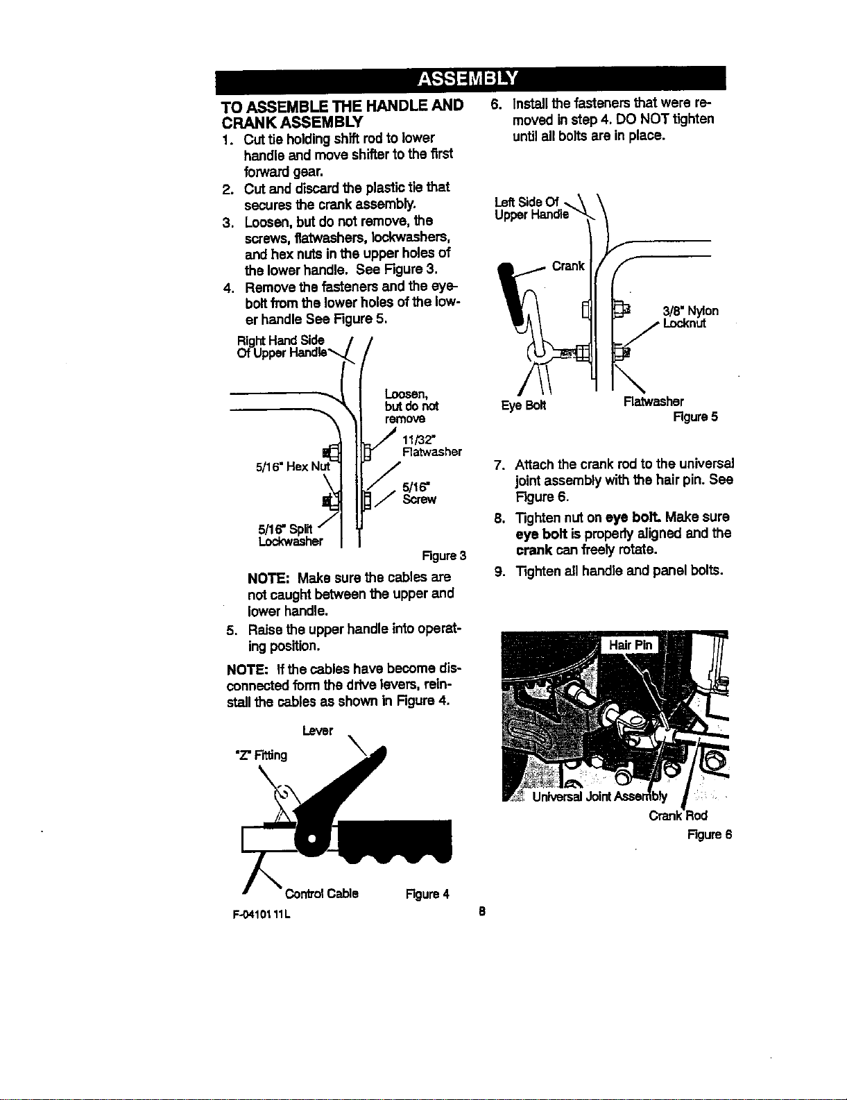
TO ASSEMBLE THE HANDLE AND
CRANK ASSEMBLY
1. Cut tie holdingshift rodto lower
handle and move shifterto the first
forward gear.
2. Cut and discardthe plastic tie that
secures the crank assembly.
3. Loosen, but do not remove, the
screws, f_twashers, Iockwashers,
and hex nuts in the upper holes of
the lower handle. See Figure 3.
4. Remove the fasteners and the eye-
boltfrom the lowerholes of the low-
er handle See Figure 5.
RightHand Side j
OfUpperHandle_
5/16" Hex Nut_:_
/
LooseN_
but do not
remove
11/32"
Ratwasher
Rgum 3
NOTE: Make sure the cables are
not caught between the upper and
lower handle,
5. Raise the upper handle into operat-
ingposition,
NOTE: If the cables have become dis-
connected form the drive levers, rein-
stall the cables as shown in Figure 4.
6. Install the fasteners that were re-
moved instep 4. DO NOT tighten
until all bolts are in place.
LeftSideOf
Upper
3/8= Nylon
Locknut
Eye Bolt Ratwasher
Rgure5
7. Attach the crank rodto the universal
joint assembly with the hair pin. See
Figure 6.
8. "lighten nut on eye bolt. Make sure
eye bolt is properly aligned and the
crank can fl'eely route.
9. Tighten all handle and panel bolts.
Cren_Aod
Figure6
Coht_4 Cable Rgure 4
F-0410111L 8
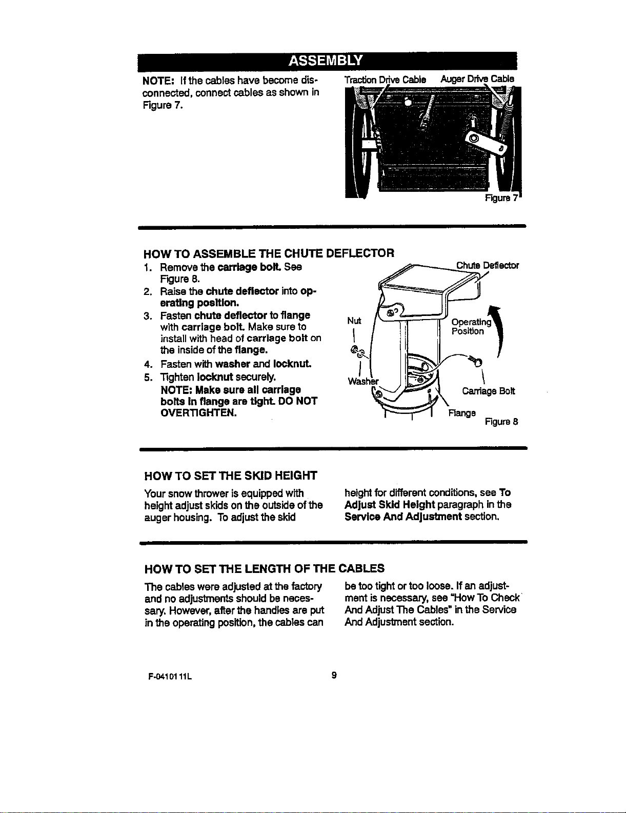
NOTE: Ifthe cables have become dis-
connected, connect cables as shown in
Figure 7.
TractionDriveCable AugerDriveCable
Figure7
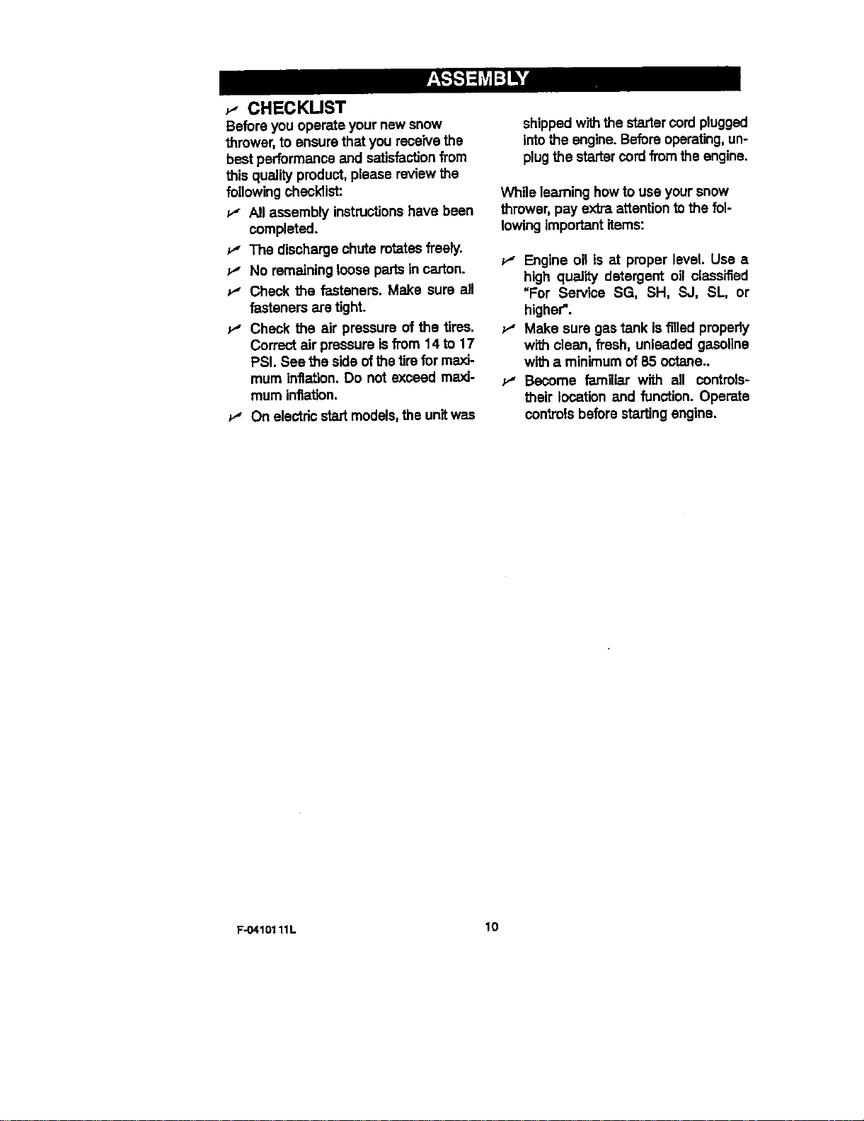
HOW TO ASSEMBLE THE CHUTE DEFLECTOR
1. Remove the carriage boll See
Figure 8.
2. Raise the chute deflector into op-
erating position.
3. Fasten chute deflector toflange
with carriage bolt. Make sure to
install with head of carriage bolt on
the inside of the flange.
4. Fasten with washer and Iocknut.
5. "Rghten Iooknut securely.
NOTE: Make sure all cerriage
bolts in flange are tight. DO NOT
OVERTIGHTEN.
De_ector
jT=z=._._Jj...... __
Nut / -- _, Operatng_l
I I Iii I_o_.oo-I
/k. ,--.or
Figure8
HOW TO SET THE SKID HEIGHT
Your snow thrower is equipped with
height adjust skids on the outside ofthe
auger housing. To adjust the skid
height for different conditions, see To
Adjust Skid Height paragraph In the
Service And AdJust_nent section.
HOW TO SET THE LENGTH OF THE CABLES
The cables were adjusted at the factory
and no adjustments should be neces-
sary. However, al_erthe handles are put
in the operating position,the cables can
be too tightor too loose. If an adjust-
ment is necessary, see =How To Check
And Adjust The Cables" in the Service
And Adjustment section.
F-O410111L 9
_- CHECKUST
Before you operate your new snow
threwer, to ensure that you receive the
best performance and satisfac_onfrom
this quality product, please review the
followingohecldist:
All assembly instructionshave been
completed.
e" The discharge chute rotates freely.
e" No remaining loose parts in carton.
Check the fasteners. Make sure all
fasteners are tight.
v" Check the air pressure of the tires.
Correut air pressure isfrom 14 to 17
PSI. See the side of the _re for maxi-
mum inflation. Do not exceed maxi-
mum inflation.
1t" On e/ectricstart medals, the unitwas
shipped with the starter cordplugged
intothe engine. Before operating,un-
plug the starter cordfrom the engine.
While learning how to use your snow
thrower, pay extra attention to the fol-
lowing important items:
v_ Engine oil is at proper level Use a
high quality detergent oil classified
"For Service SG, SH, SJ, SL, or
higher".
Make sure gas tank is filled propedy
with clean, fresh, unleaded gasoline
w_ a minimum of 85 octane..
Become familiar with all controls-
their location and function. Operate
controls before starting engine.
F-O410111L 10
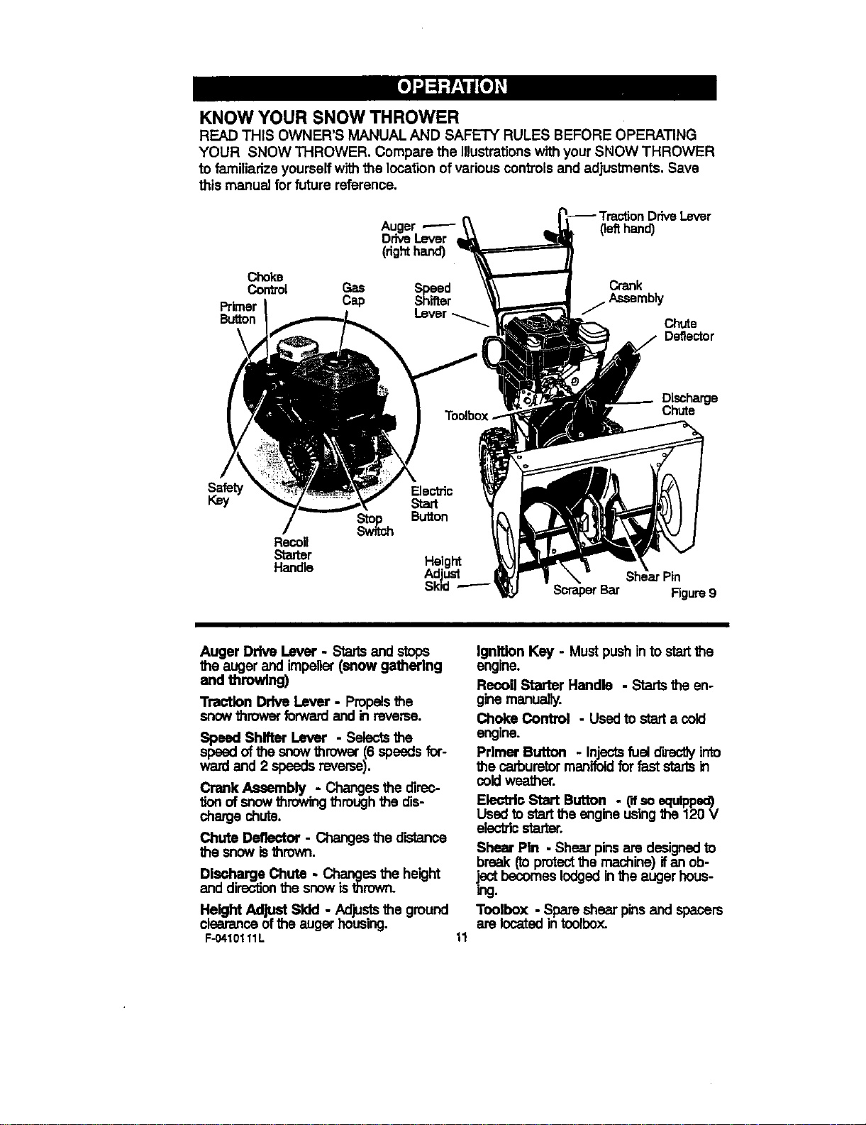
KNOW YOUR SNOW THROWER
READ THIS OWNER'S MANUAL AND SAFETY RULES BEFORE OPERATING
YOUR SNOW THROWER. Compare the illustrationswith your SNOW THROWER
to familiarize yourself with the location of various controlsand adjustments. Save
this manual for future reference.
(righthand)
(lefthand)
Choke
Control Gas Crank
Primer Cap / Assembly
Button Chute
Deflector
Discharge
Chute
Safety
Key
Recoil
Starter
Handle
ScraperBar Figure9
Auger Drive Lever. Startsand stops
the auger and impeller(snow gathering
and throwing)
Traction Drive Lever - Propelsthe
snowthrower forwardand h reverse.
Speed Shifter Lever - Selectsthe
spsed of the snow thrower (6 speads for-
wa,,dand 2 speeds reverse).
Crank Assembly - Changes the direc-
tion of snow throwingthrough the dis-
charge chute.
Chute Deflector - Changes the distance
the snow isthrown.
Discharge Chute. Changes the height
and directionthe snow isthrown.
Height Adjust Sldd - Adjuststhe ground
clearanceof the auger housing.
F-0410111L
11
Ignition Key - Must push into startthe
engine.
Recoil Starter Handle - Starts the en-
ginemanually.
Choke Control - Usedto startacold
engine.
Primer Button . Injectsfuel directJyinto
the carburetormanifold for fast stads in
coldweather.
Electric Start Button - Ofso equipped)
Used to startthe engine using the 120 V
electric starter.
Shear Pin - Shear pinsare designedto
break (toprotectthe machine) ifan ob-
j._ becomes lodged inthe auger hous-
_J.
Toolbox - Spare shear pinsand spacers
are located in toolbox.
The operation of any snowthrower can
resultin foreign objects being thrown
intothe eyes, which can resultin se-
vere eye damage. Always wear safety
glasses or eye shields while operating
the snow thrower.
We recommend standard safety
glasses or a wide vision safety mask for
over your glasses.
A ARNING: Read Owner's
Manual before operaUng
machlne. Never direct dls-
charge toward bystanders. Stop the
engine before unclogging discharge
chute or auger housing and before
leaving the machine.
TO STOP YOUR
SNOW THROWER
1. To stop throwing snow, release the
auger drive lever.
2. To stop the wheels, release the
traction drive lever.
3. To stop the engine, pull out the
safety key.
CAUTION: To stop the engine, do not
move the choke conb'ol to CHOKE
position. Backfire or engine damage
can occur.
TO CONTROL SNOW DISCHARGE
1. Turn the chute controlrod to set the
direction ofthe snow throwing.
2. Loosen the wing knob on the chute
deflector and move the deflector to
set the distance. Move the de_ector
(Up) for more distance, (Down) for
less distance. Then tighten the
wing Imob (See Figure 10).
Wing Knob
F-O410111L
HOW TO MOVE FORWARD AND
BACKWARD
1. To shift,release the traction drive
lever (left hand) and move the
speed shifter lever to the speed you
desire. Ground speed isdeter-
mined by snow conditions. Select
the speed you desire by moving the
speed shifterleverleftintotheap-
propriatenotcheson theshiftlever
plate:
Speeds 1,2 - Wet, Heavy
Speed 3 - Light
Speed 4 - Very Ught
Speed 5,6 - Transport only
2. Engage the traction drive lever (left
hand). As the snowthrower starts
to move, maintain a firm hold on the
handles, end guide the snow throw-
er along the clearing path. Do not
attempt to push the snow thrower.
3. To move the snow thrower back-
ward, move the speed shi_er lever
right intofirst or second reverse and
engage the traction drive lever (left
hand).
IMPORTANT: Do not move the speed
shifter lever while the traction lever is
down.
TO THROW SNOW
1, Push down the auger driver lever
(right hand),
2. Release to stop throwing snow.
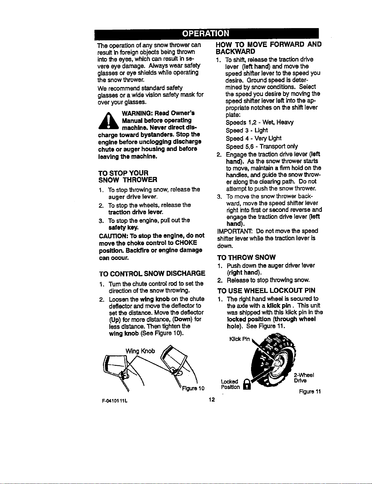
TO USE WHEEL LOCKOUT PIN
1. The right hand wheel is secured to
the axle with a Idick pin, This unit
was shippedwith this Idickpin inthe
locked position (through wheel
hole). See Figure 11.
K]ickPin
j,
-Wheel
Locked Drive
Position
Figure11
12
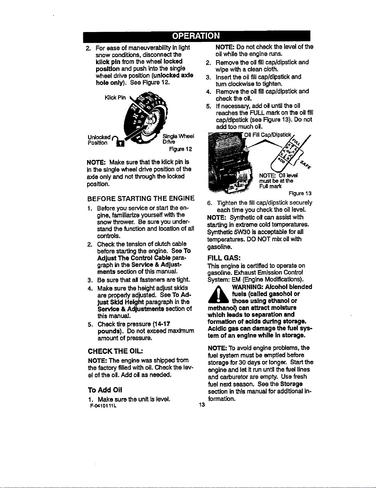
,
Foreaseofmaneuverabilityinlight
snow conditions, disconnect the
kllck pin from the wheel locked
position and push intothe single
wheel drive position (unlocked axle
hole only). See Figure 12.
K]ickPin
Unlocked Single Wheel
Position D_ive
Figure 12
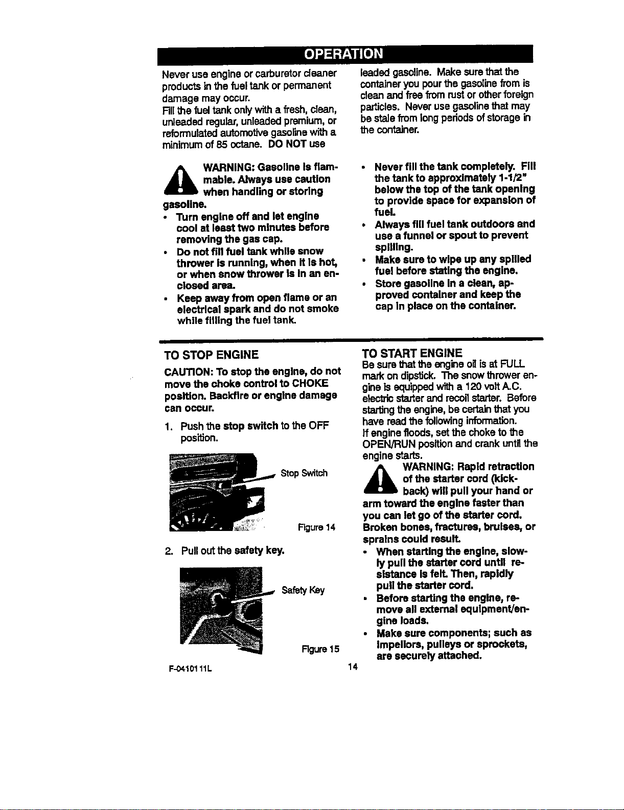
NOTE: Do not check the level of the
oilwhile the engine runs.
2. Remove the oilfill cab/dipstickand
wipe with a clean cloth.
3. Insert the oilfill cab/dipstick and
turn clockwise to tighten.
4. Remove the oNfillcab/dipstick and
check the oil
5. If necessary, add oil untilthe oil
reaches the FULL mark on the oilfill
cap/dipstick (see F_ure 13). Do not
add too much oil.
NOTE: Make sure that the Idiokpinis
in the single wheel drive position ofthe
axle only and not through the locked
position.
BEFORE STARTING THE ENGINE
1. Before you service or startthe en-
gine, familiarize yourseff with the
snow thrower. Be sure you under-
stand the function and locationof all
controls.
2. Check the tension of clutchcable
before startingthe engine. See To
Adjust The Control Cable para-
graph in the Service & Adjust-
merits section of this manual.
3. Be sure that all fasteners are tight.
4. Make sure the height adjust skids
are pmpedy adjusted. See To Ad-
just Skid Height paragraph in the
Service & Adjustments sectionof
this manual.
5. Checktire pressure (14-17
pounds). Do not exceed maximum
amount of pressure.
CHECK THE OIL:
NOTE: The engine was shipped from
the fectoPJfilled with oil. Check the lev-
el of the oil. Add oilas needed.
To Add Oil
1. Make sure the unit is level.
F-0410111L
%
NOTE: OII level
must be at the
Full mad(
Figure 13
6. Tighten the fill cap/dipstick securely
each time you check the oillevel.
NOTE; Synthetic oilcan assist with
starting in extreme cold temperatures.
Synthetic 5W30 is acceptable for all
temperatures. DO NOT mixo=1with
gasoline.
FILL GAS:
This engine is certifiedto operate on
gasoline. Exhaust Emission Control
System: EM (Engine Modifications).
4_b WARNING: Alcohol blended
fuels (eelied gasohol or
those using ethanol or
methanol) can attract moisture
which leads to separation and
formation of acids during storage.
Acidic gas can damage the fuel sys-
tem of an engine while in storage.
NOTE; To avoid engine problems, the
fuel system must be emptied before
storage for 30 days or longer. Start the
engine and let it run until the fuel lines
and carburetor are empty. Use fresh
fuel next season. See the Storage
section in this manual for additionalino
formation.
13
Never use engine or carburetor cleaner
products in the fuel tank or permanent
damage may occur.
RII the fuel tank only_ a fresh,dean,
unleaded regular, unleadedpremium, or
reformulated automotive gasolinewith a
minimumof 85 octane. DO NOT use
4_b WARNING: Gasoline Is flam-
mable. Always use caution
when handling or storing
gasolins.
• Turn engine off and let engine
cool at least two minutes before
removing the gas cap.
Do not fill fuel tank while snow
thrower is running, when it is hot,
or when snow thrower is in an en-
closed area.
Keep away from open flame or an
electrlcal spark and do not smoke
while filling the fuel tank.
leaded gasoline. Make sure that the
containeryou pourthe gasolinefrom is
clean and free from rustor otherforeign
particles. Never use gasolinethat may
be staJefrom long periodsof storagein
the container.
Never fill the tank completely. Fill
the tank to approxlmataly 1-1/2"
below the top of the tank openlng
to provide space for expansion of
fuel.
Always fill fuel tank outdoors and
use a funnel or spout to prevent
spilling.
Make sure to wipe up any spilled
fuel before stating the engine.
Store gasoline In a clean, ap-
proved container and keep the
cap in place on the container.
TO STOP ENGINE
CAUTION: To stop the engine, do not
move the choke control to CHOKE
position. Backfire or engine damage
can occur.
1. Push the stop switch to the OFF
posi_on.
StopSwitch
Figure14
2, Pull out the safety key,
safe,/
F-0410111L
Figure15
TO START ENGINE
14
Be sure that the engine oHisat FULL
mark on dip_ck. The snow thrower en-
gine is equippedwith a 120 volt/_C.
electricstarterand recoilstarter.Before
startingtheengine,be certainthatyou
have readthefollowinginformation.
Ifenginefloods,setthechoketothe
OPEN/RUN positionand crankuntilthe
enginestarts.
_k ARNING: Rapid retraction
of the starter cord (kick-
back) will pull your hand or
arm toward the engine faster than
you can let go of the starter cord.
Broken bones, fractures, bruises, or
sprains could result.
• When starting the engine, slow-
ly pull the starter cord until re-
slstanco is fell Then, rapidly
pull the starter cord.
Before starting the engine, re-
move all external equipment/en-
gine loads.
• Make sure components; such as
impellors, pulleys or sprockets,
are securely attached.
A ARNING:Thestarteris
equippedwithathree-wire
powercordandplugandis
designedtooperateon120voltAC
householdcurrent.It mustbeprop-
erlygroundedatalltimesto avoid
theposslbifityofelectricalshock
whichmay be injurious to operator.
Follow all inst_'uctions carefully
as set forth In the "To Start En-
gine" section.
• Determine that your house wiring
Is a three-wire grounded system.
Ask a licensed electrician If you
are not sure. If your house wire
system is not a throe-wire system,
do not use this electric starter un-
der any conditions.
If your system Is grounded and a
three-hole receptacle is not avail-
able at the point your starter will
normally be used, one should be
Installed by a licensed electrician.
When connecting 120 volt AC
"Power Cord", always connect the
cord to the Switch Box on the en-
gine first, than plug the other end
Into the three-hole grounded re-
ceptacle. When disconnecting
"Power Cord", always unplug the
end in the three-hole grounded re-
ceptacle first.
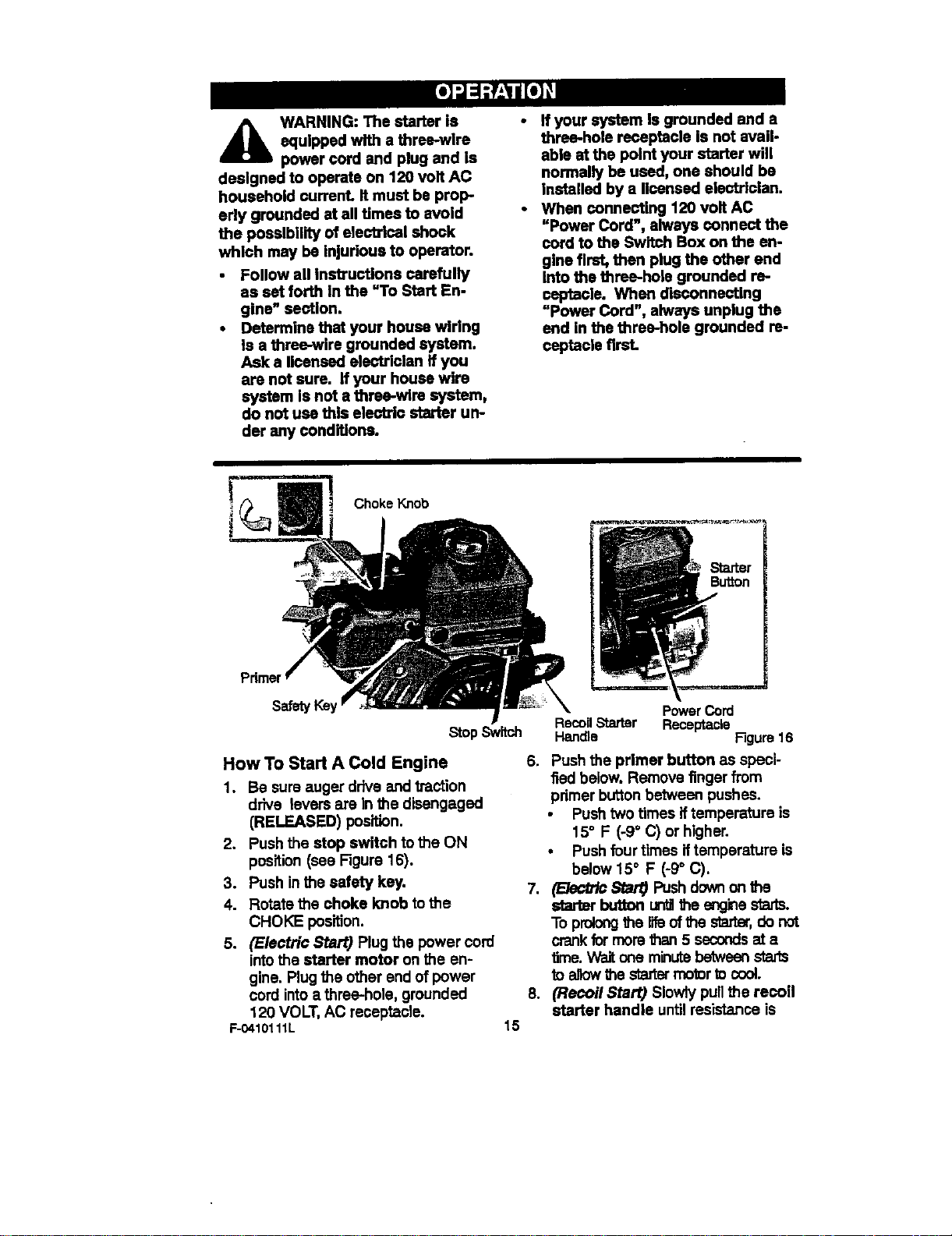
Choke Knob
Pdmer
safetyKey
Stop Switch
How To Start A Cold Engine 6.
1. Be sure auger drive and traction
drive levers are in the disengaged
(RELEASED) position.
2. Push the stop switch tothe ON
position (see Figure 16).
3. Push inthe safety key. 7.
4. Rotate the choke knob to the
CHOKE position.
5. (Electric Start) Plug the power cord
intothe starter motor on the en-
gine. Plugthe other end of power
cord intoa three-hole, grounded 8.
120 VOLT, AC receptacle.
F-0410111L 15
PowerCord
RecoilStarter Receptacle
Handle F]gum 16
Push the primer button as speci-
fied below. Remove finger from
pdmer button between pushes.
• Push two times if temperature is
15° F (-9° C) or higher.
• Push four times iftemperature is
below 15° F (-9° C).
(Bec_ Star0 Pushdownon f_
starer button LaYdlthe enginestads.
To prolongthe life ofthe sta,'tar,do not
crank formornthen 5 secondsata
time. Wait one minutebetweenstarts
to allowthe startermotortocool.
(Recoil Start) Slowly pullthe recoil
starter handle untilresistance is
feltandthen pull rapidlyto start the
engine. Do not allow the recoil
starter handle to snap back. Slowly
return the recoil starter handle.
9. If the engine does not start Jn5 or 6
tries, See DifficultStarting in the
=Troubleshooting Table'.
10.Allow the engine to warm up for
several minutes. As the engine
warms up, adjust the choke knob
toward the RUN position.Wait until
the engine runs smoothly before
each choke adjustment.
11. (Electric Start) First disconnect
power cordfrom receptacle. Then,
disconnectthe power cordfrom the
starter motor.
How To Start A Warm Engine
If restaK_nga warm engine after a short
shutdown, leave the choke Feverin the
off positionand do not push the primer
button, if the engine fails to start, follow
the Cold Start instructions.
Frozen Starter
Ifthe starter isfrozen and will not turn
the engine, follow the steps below.
1. Pullas much starter rope as pos-
sible out of the starter.
2. Release the starter handle and let it
snap back against the starter. Re-
peat untilthe engine starts.
Warm engines will cause condensation
in coldweather. To prevent possible
fTeeze-up of recoil starter and engine
controls, proceed as follows after each
snow removaljob.
1. With engine off, alisw engine to cool
for several minutes.
2. Pullstarter rope very slowly until re-
sistance is felt, then stop. Allow the
starter rope to reooi_.Repeat three
times.
3. W'_ the engine not running, wipe all
snow and moisture from the carbu-
retor cover in area of controls and
levers. Also, move the choke control
and starter handle several times.
A WARNING: Never run en-
gine indoors or in enclosed,
poorly ventilated areas. En-
gine exhaust contains CARBON
MONOXIDE, AN ODORLESS AND
DEADLY GAS. Keep hands, feet,
hair and loose clothing away from
any moving parts on engine and
snow thrower.
Engine parts, especially the muf-
fler, become extremely hot. Se-
vere thermal burns can occur on
contact. Allow the engine to cool
before touching.
Never allow chlldran to operate
the snow thrower. Never allow
adults to operate the snow throw-
er without proper instruction.
Keep the area of operation clear
of all persons, particularly small
children and pets.
Never leave the snowthmwer un.
attended while the engine Is run-
ning. Anyone operating the en-
gine or equipment must carefully
read and understand the operat-
Ing instructions.
F.O410"_11L 16
TO REMOVE SNOW FROM AUGER
_IL ARNING: Do not attempt
to remove snow or debris
that may become lodged in
auger with your hands. Use the
cleaning stick to remove snow or
debris.
A cleaning stick isattached to the top of
the auger housing. Use the cleaning
stickto remove snow from the auger
housing.
Release auger drive lever.
Remove (do not turn) safety key.
Disconnect spark plug wire.
Do not place your hands in the au-
ger or discharge chute. Use the
cleaning stick to remove snow.
SNOW THROWING TIPS
1. For maximum snow thrower efficien-
cy in removing snow,adjust ground
speed. Go slower in deep, freezing
or wet snow. Ifthe wheels slips, re-
duce forward speed.
2. Most efficient snow throwing is ac-
complished when the snow is re-
moved immediately after iffalls.
3. For complete snow removal, sligh'dy
overlap each path previously taken.
4. The snow should be discharged
down wind whenever possible.
5. For normal usage, set the skids so
that the scraper bar is 1/8" above
the skids. For extremely hard-
packed snow surfaces, adjust the
skids upward so that the scraper
bar touches the ground.
6, On gravel or crushed rock surfaces,
.
,
9.
set the skids at 1-1/4" below the
scraper bar. See To Adjust Skid
Height paragraph in the Service &
Adjustments section of this manu-
al. Rocks and gravel must not be
picked up and thrown bythe ma-
chine.
After the snow throwing job has
been completed, allow the engine to
idlefor a few minutes, which will
melt snow and accumulated ice off
the engine.
Clean the snow thrower thoroughly
after each use.
Remove ice and snow accumulation
and all debris from the entire snow
thrower, and flushwith water (ifpos-
sible) to remove all salt or other
chemicals. Wipe snow thrower dry.
F-0410111L 17
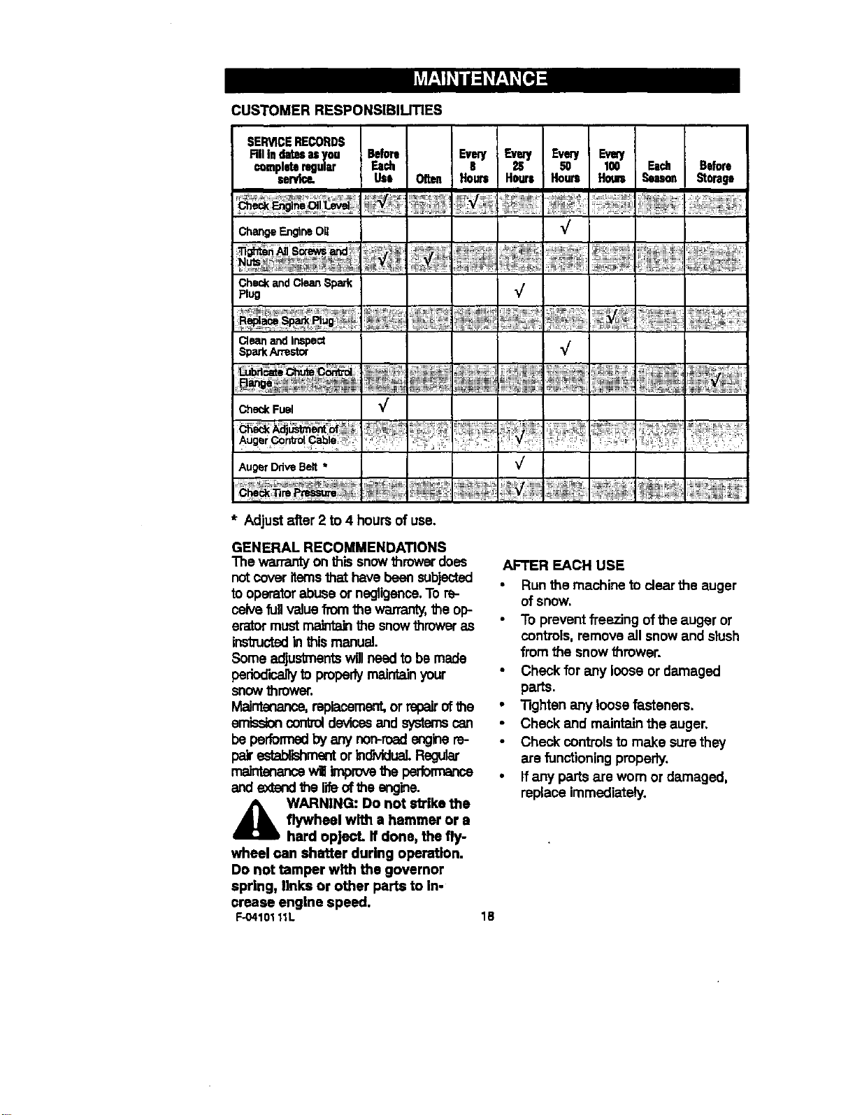
CUSTOMER RESPONSIBILITIES
SERVICERECORDS
RII indatesasyou Before Even/ Every Eve_ Even/
Completeregular Each B 2S 50 100 Ea_ Before
servl_ Use O[t_ Hours Hours Hours Houm Seas_ Storage
ChangeEn_neO_
¢
CheckandCleanSpark
Plug
Cleanand InspeCt
SparkArrestor
_b_ _: ............ :,i '.' _.iil:
;!iJ!i :l..........................................
Check Fuel 3/" I
I
,u,e,on,,Se,.
iiiiliiiii!! iiiiiii!i'
* Adjust after 2 to 4 hours of use.
GENERAL RECOMMENDATIONS
The warrantyon this snowthrower does
not cover itemsthat have been subjected
to operatorabuse or negligence.To re-
ceive fullvalue from the warranty,the op-
erator mustmalrda_ the snowthrower as
instructedin this manual.
Some adjustmentswillneed to be made
periodicallyto properlymaintainyour
snow thrower.
MalrTtenance,radlacement,or repairof the
emissioncontrol devicesand systemscan
be performedby any _o_ engine_-
pa_ establishmentor indviduaL Regular
ma_-r_e_er_e win improve the pedo_Ta,_e
and ex|andther_.oftheangine.
_b ARNING: Do not strike the
flywheel with a hammer or a
hard opject. If done, the fly-
wheel can shatter during operation.
Do not tamper with the governor
spring, links or other parts to in-
crease engine speed.
F-O4101 11L
AFTER EACH USE
• Run the machine to clear the auger
of snow.
To prevent freezing of the auger or
controls, remove all snow and slush
from the snow thrower.
Check for amy loose or damaged
parts.
• TIghtan any loose fasteners.
Check and maintain the auger,
Check controls to make sure they
are functioning properly.
• If any parts ate worn or damaged,
replace immediately.
18
ENGINE SPECIFICATIONS
HORSEPOWER 6 HP
DISPLACEMENT 206 cc
BORE 68mm (2.677 in.)
STROKE 56ram (2.205 in.)
GASOLINE 3 quarts
CAPACITY {unleaded)
OIL CAPACITY
(18 oz capacity) 5W30
SPARK PLUG: Champion RJ19LM
(Gap .030 in.) or
equivalent
VALVE Intake: 0.004-0.006 in.
;LEARANCE: Exhaust: 0.009..0.011 in.
ARMATURE
AIR GAP: 0.010-0.014 in.
POWER RATINGS
The power ratings for an individual
engine model are initiallydeveloped by
starting with SAE (Society ofAutomo-
tive Engineers) code J1940 (Small
Engine Power & Torque Rating Proce-
dure) (Revision 2002-05). Given both
the wide array ofproducts on which our
engines are placed, and the variety of
environmental issues applicable to
operating the equipment, itmay be that
the engine you have purchasedwill not
develop the rated horsepower when
used in a piece of power equipment
(actual "on-site" power). This difference
is due to a variety of factors including,
but not limited to, the following: differ-
ences in altitude,temperature, baro-
metric pressure, humidity,fuel, engine
lubrication, maximum governed engine
speed, individualengine to engine
variability, design ofthe particular piece
of power equipment, the manner in
which the engine is operated, engine
run-in to reduce frictionand clean out of
combustion chambers, adjustments to
the valves and carburetor,and other
factors. The power ratings may also be
adjusted based on comparisons to
other similar engines utilized in similar
applications, and willtherefore not
necessarily match the values derived
using the foregoing codes.
F-04101 11L
SNOW THROWER
AUGER DRIVE BELT
Adjust the auger drive belt after the first
2 to 4 hours of use, again about mid-
season and twice each season theraaf-
tar (See to "Belt Adjustment" in the
Service and Adjustment section).
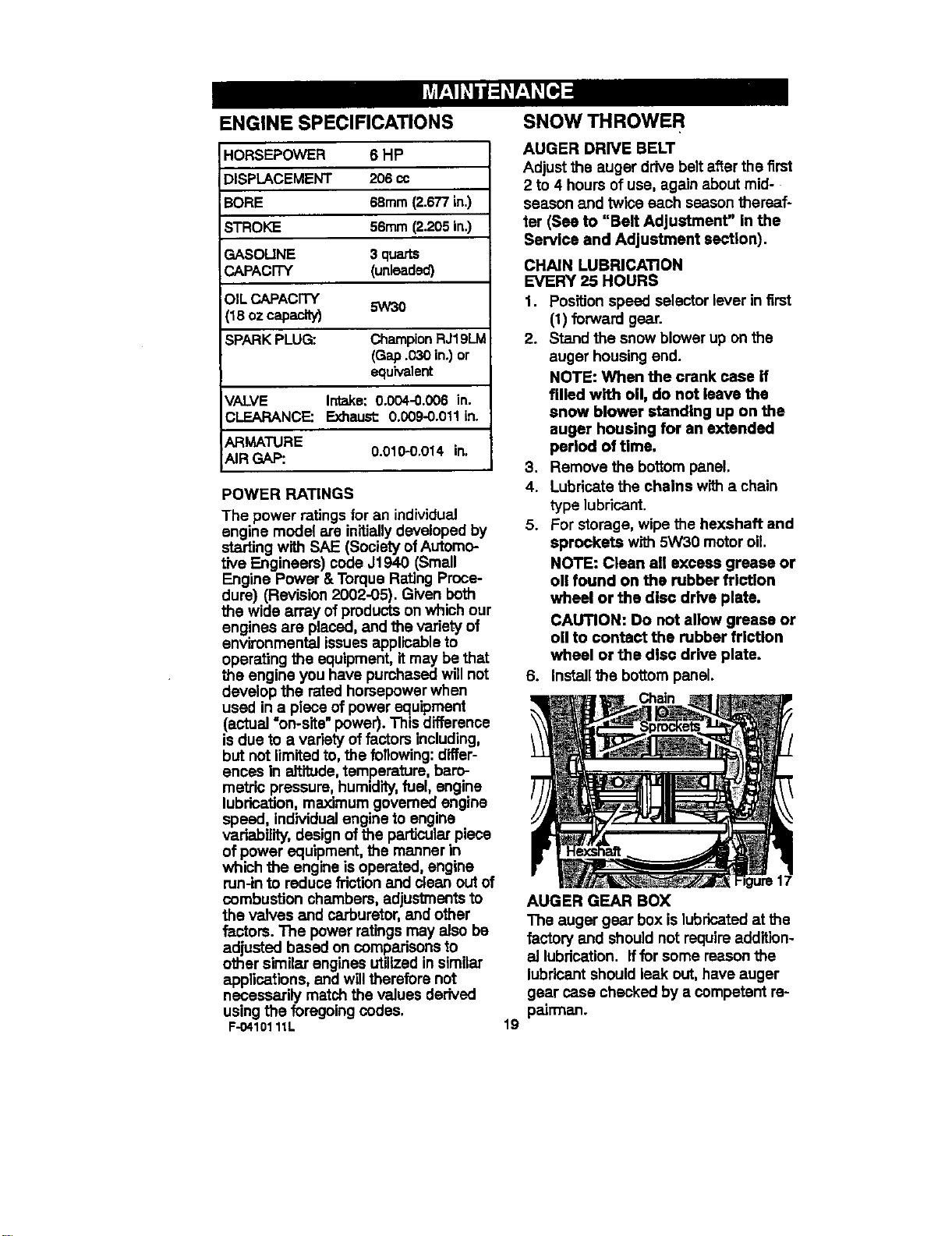
CHAIN LUBRICATION
EVERY 25 HOURS
1. Position speed selector lever in first
(1) forward gear.
2. Stand the snow blower up on the
auger housing end.
NOTE: When the crank case if
filled with oil, do not leave the
snow blower standing up on the
auger housing for an extended
period of time.
3, Remove the bottom panel.
4. Lubricate the chains with a chain
type lubricant.
5. For storage, wipe the hexshaft and
sprockets with 5W30 motor oil.
NOTE: Clean all excess grease or
oll found on the rubber friction
wheel or the disc drive plate.
CAUTION: Do not allow grease or
oil to contact the rubber friction
wheel or the disc drive plate.
6. Install the bottom panel.
Chain
19
AUGER GEAR BOX
The auger gear box is lubricated at the
factory and should not require addition-
al lubrication. If for some reason the
lubdcant should leak out, have auger
gear case checked by a competent re-
pairmen.
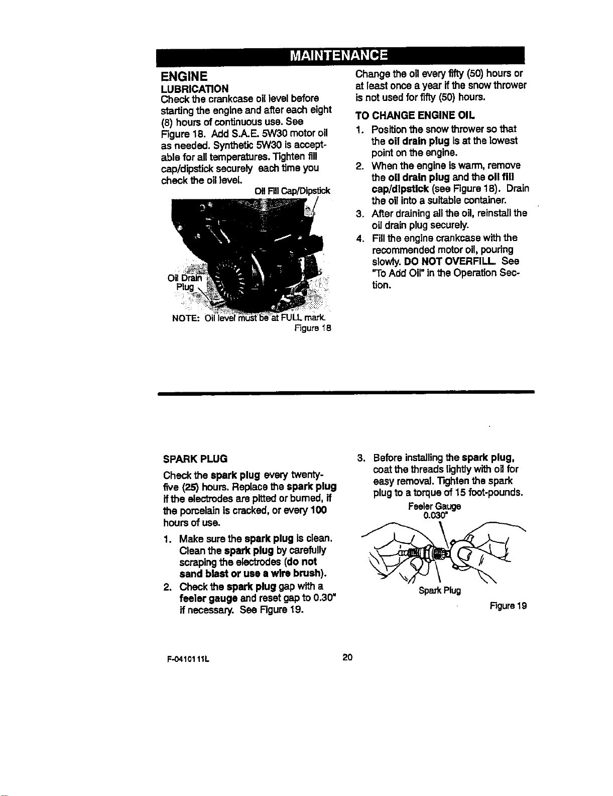
ENGINE
LUBRICATION
Check the crankcase oillevel before
starting the engine and after each eight
(8) hours ofcontinuoususe. See
Figure 18. Add S.A.E. 5W30 motorog
as needed. Synthetic 5W30 is accept-
able for all tempemturas. "_ghtenfill
cap/dipstick securely each time you
check the oil level.
OIIFillCap/Dipstick
NOTE: O
FULL mark.
Figure 18
Change the all every fifty (50) hoursor
at least once a year if the snow thrower
isnot used for fiity (50) hours.
TO CHANGE ENGINE OIL
1. Positionthe snow thrower so that
the oil drain plug isat the lowest
point on the engine.
2. When the engine iswarm, remove
the oil drain plug and the oil fill
cap/dipstick (see Figure 18). Drain
the oilintoa suitable container.
3. After drainingall the oil, reinstallthe
oil drain plug securely.
4. Fillthe engine crankcase with the
recommended motoroil, pouring
slowly. DO NOT OVERFILL See
'To Add Oil"in the Operation Sec-
tion.
SPARK PLUG
Check the spark plug every twenty-
five (25) hours. Replace the spark plug
ifthe electrodes are pittedor bumed, if
the pomalaln iscracked, or every 100
hours of use.
1. Make sure the spark plug is clean.
Clean the spark plug by carefully
scraping the electrodes (do not
sand blast or use a wire brush).
2. Check the spark plug gap with a
feeler gauge end reset gap to 0.30"
if necessary. See Figure 19.
3. Before installingthe spark plug,
coat the threads lightly with oilfor
easy removal. TIghten the spark
plug to a torque of 15 foot-pounds.
FeelerGauge
0.030"
Spark Plug
Figure19
F-0410111L 20
,_ WARNING: Always discon-
nect the spark plug wire and
place it where It cannot
make contact with spark plug to pre-
vent accidental starting when mak-
ing any adjustments or repairs.
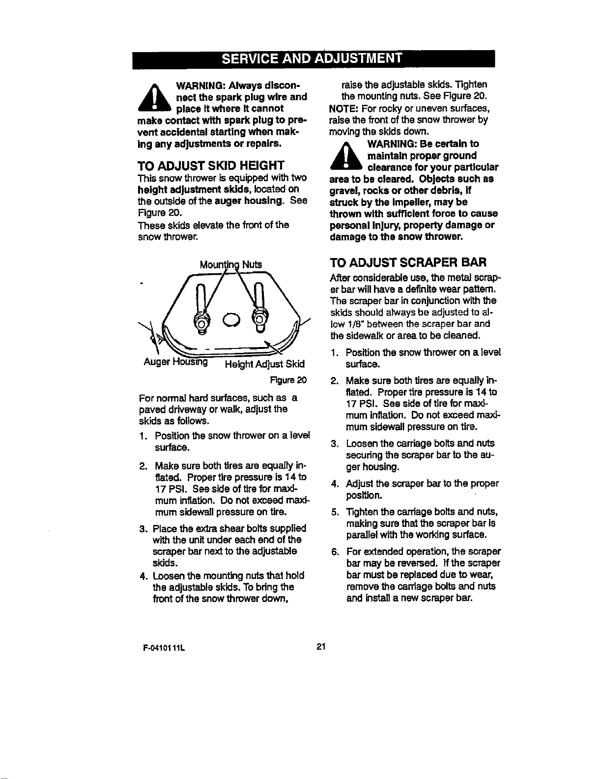
TO ADJUST SKID HEIGHT
This snow thrower isequipped with two
height adjustment skids, located on
the outside ofthe auger housing. See
Figure 20.
These skids elevate the front of the
snow thrower.
Nuts
©
Auger Height Adjust Skid
Figure20
For normal hard surfaces, such as a
paved driveway orwalk, adjust the
skids as follows.
1. Positionthe snow thrower on a level
surface.
2. Make sure bothtires are equally in-
flated. Proper tire pressure is 14to
17 PSI. See side of tire for maxi-
mum inflation. Do not exceed maxi-
mum sidewall pressure on tire.
3. Place the extra shear boltssupplied
with the unitunder each end of the
scraper bar nextto the adjustable
skids.
4. Loosen the mounting nuts that hold
the adjustable skids. To bdng the
front of the snow thrower down,
raise the adjustable skids.Tighten
the mounting nuts.See Figure 20.
NOTE: For rocky or uneven surfaces,
raise the front of the snow thrower by
movingthe skids down.
_lb ARNING: Be certain to
maintain proper ground
clearance for your particular
area to be cleared. Objects such as
gravel, rocks or other debris, if
struck by the impeller, may be
thrown with sufficient force to cause
personal injury, property damage or
damage to the snow thrower.
TO ADJUST SCRAPER BAR
Alter considerable use, the metal scrap-
er bar will have a definite wear pattern.
The scraper bar in conjunction with the
skids should always be adjusted to al-
low 1/8" between the scraper bar and
the sidewalk or area to be cleaned.
1. Positionthe snowthrower on a level
surface.
.
3.
.
5.
.
Make sure bothtires are equally in-
flated. Proper tire pressure is 14 to
17 PSI. See side of tire for maxi-
mum inflation. Do not exceed maxi-
mum sidewall pressure on tire.
Loosen the cardage bolts and nuts
secudng the scraper bar to the au-
ger housing.
Adjust the scraper bar tothe proper
position.
Tighten the carriage bottsand nuts,
making sure that the scraper bar is
parallel with the working surface.
For extended operation, the scraper
bar may be reversed. If the scraper
bar must be replaced due to wear,
remove the carriage boltsand nuts
and installa new scraper bar.
F.0410111L 21
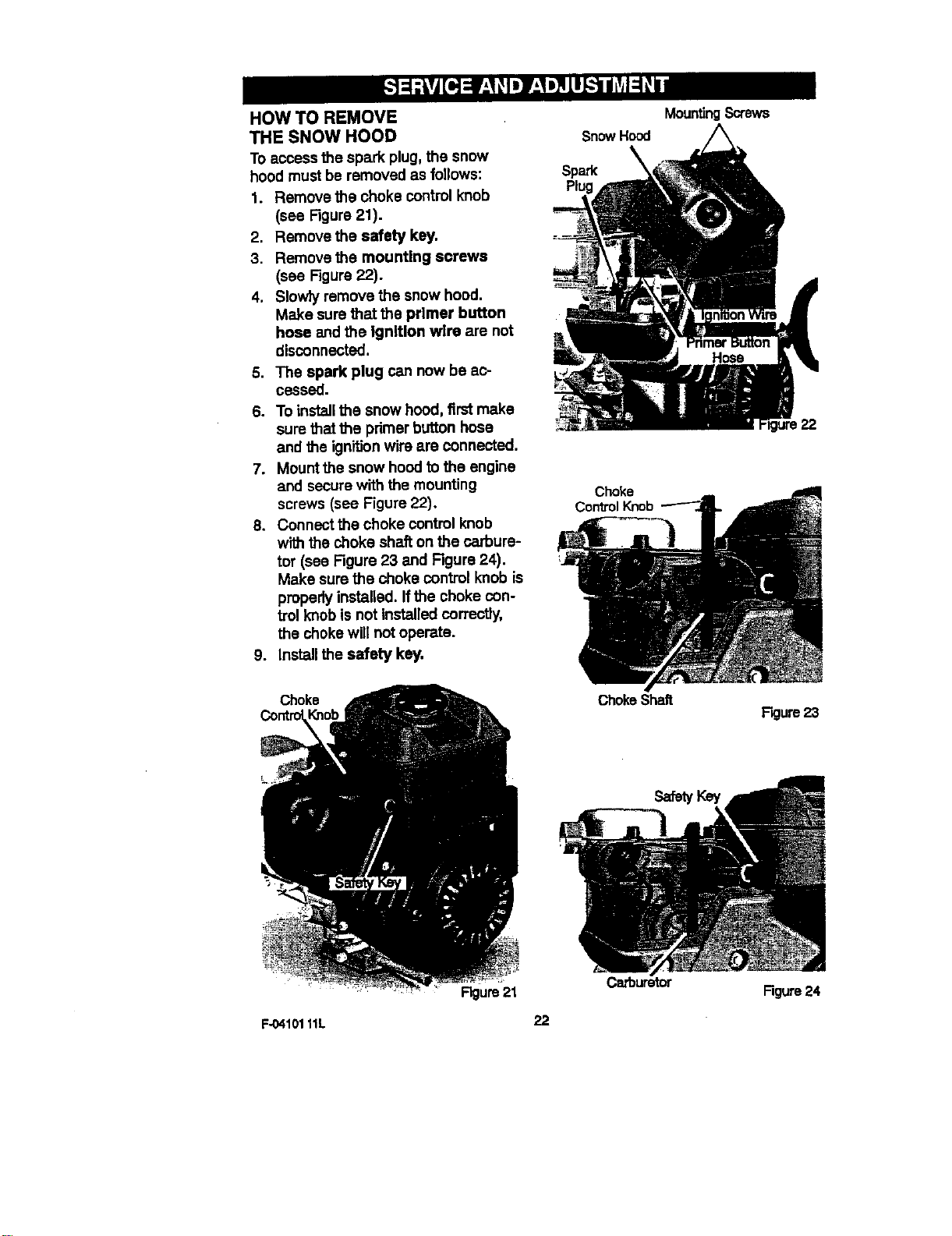
HOW TO REMOVE
THE SNOW HOOD
To access the spark plug,the snow
hood must be removed as follows:
1. Remove the choke controlknob
(see Figure21).
2. Remove the safety key.
3. Remove the mounting screws
(see Figure22).
4. Slowly remove the snow hood.
Make sure that the primer button
hose and the Ignition wire are not
disconnected.
5. The spark plug can now be ac-
cessed.
6. To installthe snow hood, first make
sure that the primer button hose
and the ignitionwire are connected.
7. Mount the snow hoodto the engine
and secure with the mounting
screws (see Figure 22).
8. Connect the choke control knob
with the choke shafton the carbure-
tor (see Figure 23 and Figure 24).
Make sure the choke control knob is
properly installed. If the choke con-
trol knob is not installedcorrectJy,
the choke will not operate.
9. Install the safety key.
Snow Hood
Spark k
P_
Choke
Control Knob
MountingScrews
22
Choke
ChokeShah
F_ure 23
Cafouretor
Figure24
Rgure21
F-0410111L 22
BELT ADJUSTMENT
Traction Drive Belt
The traction drive belt has constant
springpressure and does not require
an adjustment. Ifthe traction drive belt
is slipping, replace the belt. See "How
To Replace The Belts" inthe Service
And Adjustment section.
Auger Drive Belt
If your snow blower will not discharge
snow,check the controlcable adjust-
ment. If itis correct, then check the
condition of the auger drive belt. If it is
damaged or loose, replace it (see "How
To Replace The Belts"in this section of
the manual).
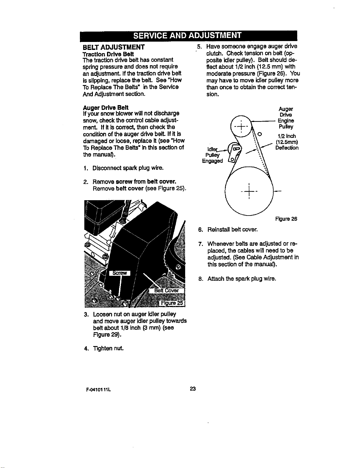
1. Disconnect spark plug wire.
2. Remove screw from belt cover.
Remove belt cover (see Figure 25).
5. Have someOne engage auger drive
clutch. Check tension on belt (op-
posite idler pulley). Belt should de-
flect about 1/2 inch(12.5 ram) with
moderate pressure (Figure 26). You
may have to move idler pulley more
than once to obtain the correct ten-
sion.
Auger
Drive
_ Engine
Pulley
O 1/2inch
(12.5mm)
Idler'E'*_"_. Defle_°n
Pul_=y
Engaged
Figure 26
6. Reinstall belt cover.
7. Whenever belts are adjusted or re-
placed, the cables will need to be
adjusted. (See Cable Adjustment in
this section ofthe mariuS.
8. Attach the spark plug wire.
.
Loosen nut on auger idler pulley
and move auger idler pulley towards
belt about 1/8 Inch (3 ram) (see
Figure 29).
4. "Rghtennut.
F-0410111L 23
HOW TO REPLACE THE BELTS
The drive belts are of special construc-
tion and must be replaced with odginal
equipment replacement belts available
from your nearest Sears service center.
Some steps require the assistance of a
second person.
How To Remove the Auger Drive Belt
Ifthe auger drive belt is damaged, the
snow thrower will not discharge snow.
Replace the damaged belt as follows.
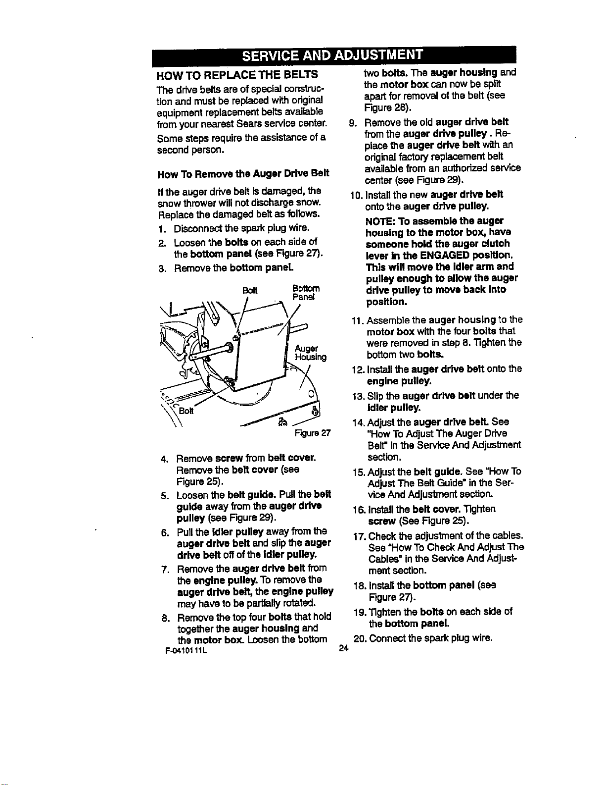
1. Disconnect the spark plugwire.
2. Loosen the bolts on each side of
the bottom panel (see Figure 27).
3. Remove the bottom panel.
\
BOlt Bottom
Panel
Auger
Housing
\ Bolt "_
Rgure27
4. Remove screw from belt cover.
Remove the belt cover (see
Figure 25).
5. Loosen the belt guide. Pullthe belt
guide away from the auger drive
pulley (see Figure 29).
6. Pull the idler pulley away from the
auger drive belt and slip the auger
drive belt off ofthe idler pulley.
7. Remove the auger drive belt from
the engine pulley. To remove the
auger drive belt, the engine pulley
may have to be partially rotated.
B. Remove the top four bolts that hold
together the auger housing and
the motor box. Loosen the bottom
F-0410111L
24
two bolts. The auger housing and
the motor box can now be spilt
apart for removal of the belt (see
F.:jure28).
9. Remove the old auger drive belt
from the auger drive pulley. Re-
place the auger drive belt wfth an
originalfactory replacement belt
available fi'om an authodzed service
center (see Figure 29).
10. Installthe new auger drive belt
ontothe auger drive pulley.
NOTE: To assemble the auger
housing to the motor box, have
someone hold the auger clutch
lever In the ENGAGED position.
This will move the idler arm and
pulley enough to allow the auger
drive pulley to move back into
position.
11. Assemble the auger housing to the
motor box with the four bolts that
were removed in step B. "i3ghtanthe
bottomtwo bolts.
12. Installthe auger drive belt ontothe
engine pulley.
13. Slipthe auger drive belt under the
idler pulley.
14. Adjust the auger drive belt. See
"How To Adjust The Auger Drive
Belt"inthe Service And Adjustment
section.
15.Adjust the belt guide. See "How To
Adjust The Belt Guide" in the Ser-
vice And Adjustment section.
16. Install the belt cover, 13ghten
screw (See Figure 25).
17. Check the adjustment of the cables.
See =HowTo Check And Adjust The
Cables" in the Service And Adjust-
ment section.
18. Installthe bottom panel (see
Figure 27).
19. "13ghtenthe bolts on each side of
the bottom panel.
20. Connect the spark plug wire.
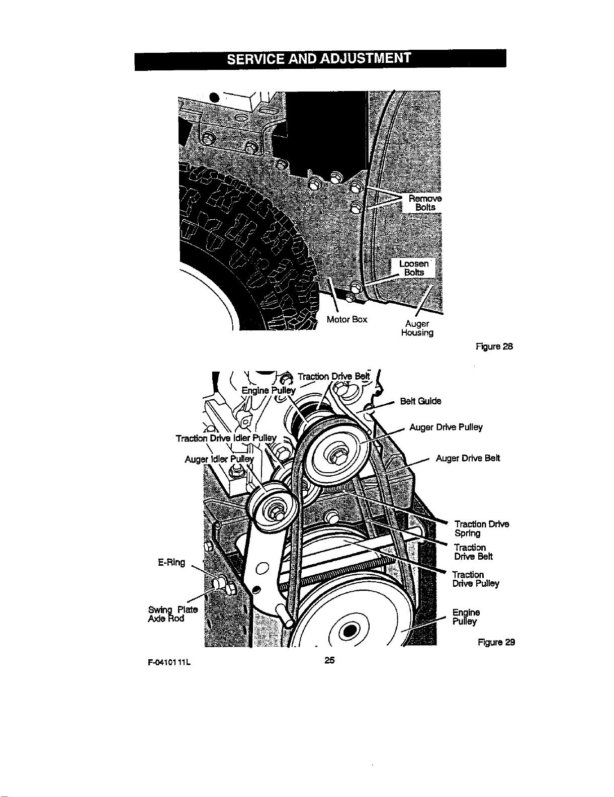
Bolts
Motor Box
Auger
Housing
Figure 28
Belt Guide
Traction
\
Auger
Auger Drive Pulley
Auger Drive Belt
E-Ring
Traction Drive
Spdng
Traction
DriveBelt
Traction
DrivePulley
Swing Plate
.aodeRod
F-04101 11L
25
Engine
Pulley
Figure29
How To Remove
The Traction Drive Belt
If the snow thrower willnot move for-
ward, check the traction drive belt for
wear or damage. If the traction drive
belt isworn or damaged, replace the
belt as follows.
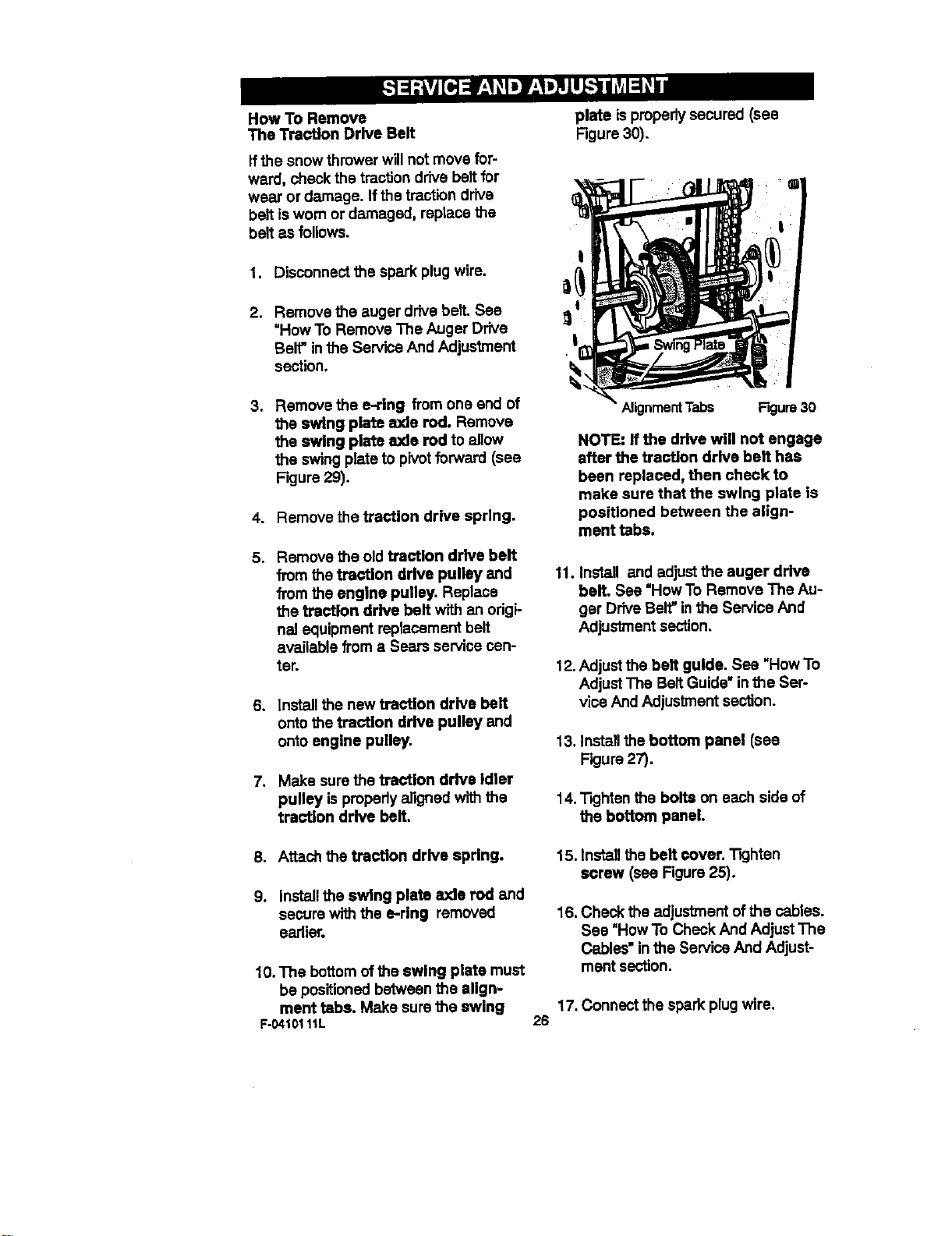
1. Disconnectthe spark plug wire.
plate ispropertysecured (see
Figure 30).
!
2. Remove the auger drive belt. See
"HowTo Remove The Auger Drive
Belt"in the Service And Adjustment
section.
3. Remove the e-ring from one end of
the swing plate axle rod. Remove
the swing plate axle rod to allow
the swing plate to pivotforward (see
Figure 29).
4. Remove the traction drive spring.
5, Remove the old traction drive belt
from the traction drive pulley and
from the engine pulley. Replace
the traction drive belt with an origi-
nal equipment replacement belt
available from a Sears service cen-
ter.
6. Install the new traction drive belt
ontothe traction drive pulley and
onto engine pulley.
7. Make sure the traction drive Idler
pulley is pmparly aligned with the
traction drive belt.
Alignment Tabs Figure 30
NOTE: If the drive will not engage
after the traction drive belt has
been replaced, then check to
make sure that the swing plata is
positioned between the align-
ment tabs.
11. Install and adjustthe auger drive
belt. See "How To Remove The Au-
ger Drive Belt" inthe Service And
Adjustment section.
12. Adjust the bell guide. See "How To
Adjust The Belt Guide" inthe Ser-
vice And Adjustment section.
13. Install the bottom panel (see
Figure 27).
14."13ghtenthe bolts on each side of
the bottom panel.
8. Attach the traction drive spring.
9. Install the swing plate axle rod and
secure with the e-ring removed
earlier.
10.The bottomofthe swing plate must
be positioned between the align-
ment tabs. Make sure the swing
F-04101 11L
15.Installthebelt cover.Tighten
screw (see Figure25).
16. Check the adjustment of the cables.
See "HowTo Check And Adjust The
Cables" in the Service And Adjust-
ment section.
17. Connect the spark plugwire.
26
BELT GUIDE ADJUSTMENT
1. Remove spark plug wire.
2. Have someone engage auger drive.
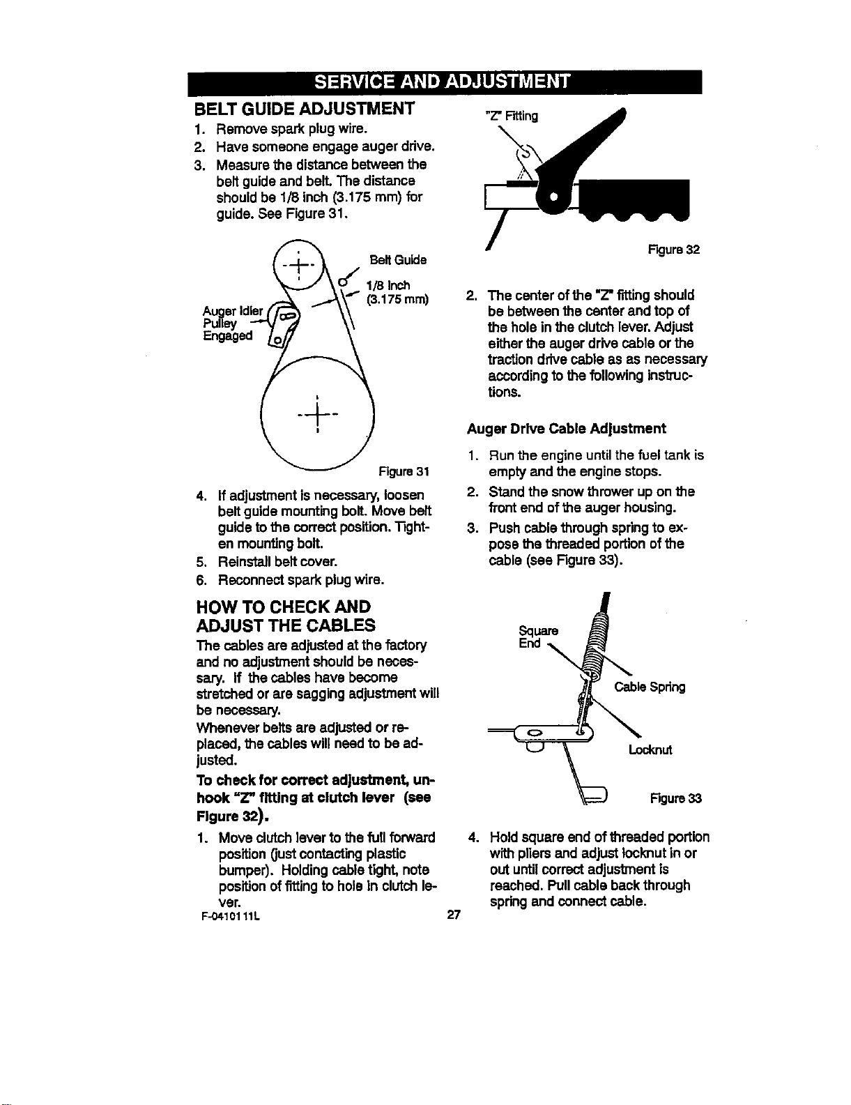
3. Measure the distance between the
belt guide and bell The distance
should be 1/8 inch (3.175 rnrn)for
guide. See Figure 31,
"Z"Fitting
_._ Belt Guide
Jko/
1 - _,.,.,_\'_' (3.175 ram)
AugerIdler(/i - \\
-
Figure 31
4. If adjustment is necessary, loosen
belt guide mounting bolt. Move belt
guide tothe correct position,Tight-
en mounting bolt.
5, Reinstall belt cover.
6, Reconnect spark plug wire,
HOW TO CHECK AND
ADJUST THE CABLES
The cables are adjusted at the factory
and no adjustment should be neces-
sary, If the cables have become
stretched or are sagging adjustment will
be necessary.
Whenever belts are adjusted or re-
placed, the cables will need to be ad-
justed.
To check for correct adjustment, un-
hook "Z" fitting at clutch lever (see
Figure 32).
1. Move clutch lever to the full forward
position (justcontacting plastic
bumper). Holding cable tight, note
positionof fittingto hole in clutchle-
ver.
F-04101 11L
F'_ure 32
2. The center of the "Z"titting should
be between the center and top of
the hole in the clutch lever, Adjust
either the auger drive cable or the
traction drive cable as as necessary
according to the following ins'_uc-
tions.
Auger Drive Cable Adjustment
1. Run the engine until the fuel tank is
empty and the engine steps.
2. Stand the snow thrower up on the
fTontend of the auger housing.
3. Push cable through spring to ex-
pose the threaded portion of the
cable (see Figure 33).
ESqLlar8
nd
Cable Spdng
=__ Locknut
Rgure33
27
4. Hold square end of threaded portion
with pliers and adjust Iccknut in or
out untilcorrect adjustment is
reached. Pullcable back through
spring and connect cable.
TRACTION DRIVE CABLE ADJUSTMENT
1. Run the engine untilthe fuel tank is
empty and the engine stops.
2. Stand the snow thrower up on the
front end ofthe auger housing.
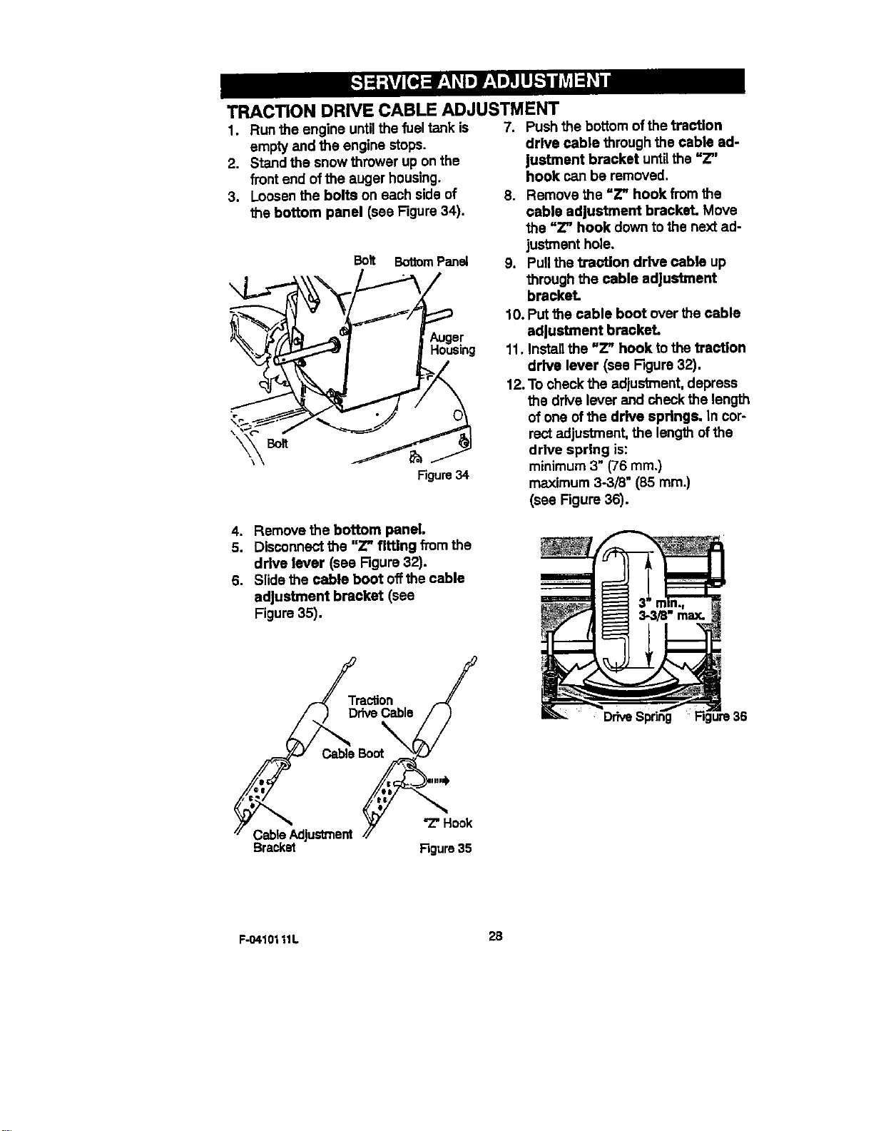
3. Loosen the bolts on each side of
the bottom panel (see Figure34).
Bolt BottomPanel
Figure34
4. Remove the bottom panel.
5. Disconnect the "Z" tiffing from the
drive lever (see Figure 32).
6, Slide the cable boot offthe cable
adjustment bracket (see
Figure 35),
7. Push the bottom ofthe traction
drive cable through the cable ad-
justment bracket untilthe =Z"
hook can be removed.
8. Remove the uZ" hook from the
cable adjustment bracket. Move
the "Z" hook down to the next ad-
jus_nent hole.
9. Pull the traction drive cable up
through the cable adjustment
bracket.
10. Put the cable boot over the cable
adjustment bracket.
11. Install the =Z" hook to the traction
drive lever (see Rgure 32).
12.To check the adjustment, depress
the drive lever and check the length
of one of the drive springs. In cor-
rect adjustment, the length ofthe
drive spring is:
minimum 3" (76 ram.)
maximum 3-3/8m(85 ram.)
(see Figure 36).
Traction /
CableBOot/F_
CableAdjustment./_ "Z"Hook
Bracket Figure35
F-O410111L 2B
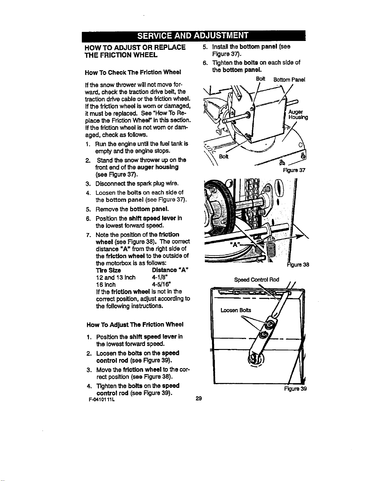
HOW TO ADJUST OR REPLACE
THE FRICTION WHEEL
How To Check The Friction Wheel
Ifthe snow thrower will not move for-
ward, check the traction drivebelt, the
traction drive cable or the friction wheel.
If the frictionwheel isworn or damaged,
it must be replaced. See "How To Re-
place the FrictionWheel" in this section.
Ifthe frictionwheel is not worn or dam-
aged, check as follows.
1. Run the engine untilthe fuel tank is
empty and the engine stops.
2. Stand the snow thrower up on the
front end of the auger housing
(see F_ure 37).
3. Disconnect the spark plugwire.
4. Loosen the bolts on each side of
the bottom panel (see Figure 37).
5. Remove the bottom panel.
6. Position the shift speed lever in
the lowest forward speed.
7. Note the position ofthe friction
wheel (see Figure 38). The correct
distance =A" from the rightside of
the friction wheel to the outside of
the motorbox is as follows:
Tire Size Distance "A"
12 and 13 inch 4-1/8"
16 inch 4-5/16"
Ifthe friction wheel isnot in the
correct position,adjust according to
the following instructions.
5. Install the bottom panel (see
Figure 37).
6. "13ghtanthe bolts on each side of
the bottom panel.
Bolt Bottom Panel
\
Auger
Housing
Figure37
Figure3B
SpeedControlRod
How To Adjust The Friction Wheel
1. Position the shift speed lever in
the lowest forward speed.
2. Loosen the bolts on the speed
control rod (see Figure 39).
3. Move the fdcUon wheel to the cor-
rect position (see Figure 38).
4. "13ghtenthe bolts on the speed
control rod (see Rgure 39).
F-04101 11L
29
Figure 39
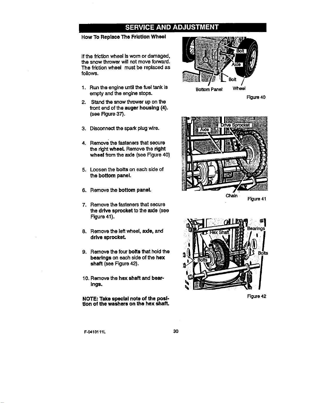
How To Replace The Friction Wheel
If the frictionwheel isworn or damaged,
the snow thrower will not move forward.
The friction wheel must be replaced as
follows.
1, Run the engine untilthe fuel tank is
empty and the engine stops.
2. Stand the snow thrower up on the
front end ofthe auger housing (4).
(see Figure37).
BottomPanel
Wheel
Rgure 40
3. Disconnectthe spark plug wire.
4. Remove the fasteners that secure
the rightwheel Remove the right
wheel from the axle (see Figure 40)
5. Loosen the bolts on each side of
the bottom panel.
6. Remove the bottom panel.
7. Remove the fasteners that secure
the drive sprocket to the axle (see
Figure 41).
8. Remove the leftwheel, axle, and
drive sprocket.
9. Remove the four bolts that holdthe
bearings on each side ofthe hex
shaft (see Figure42).
10. Remove the he)( shaft and bear-
Ings.
NOTE: Take special note of the posi-
tion of the washers on the hex shaft.
Chain
Rgure 41
Figure42
F-04101 11L 30
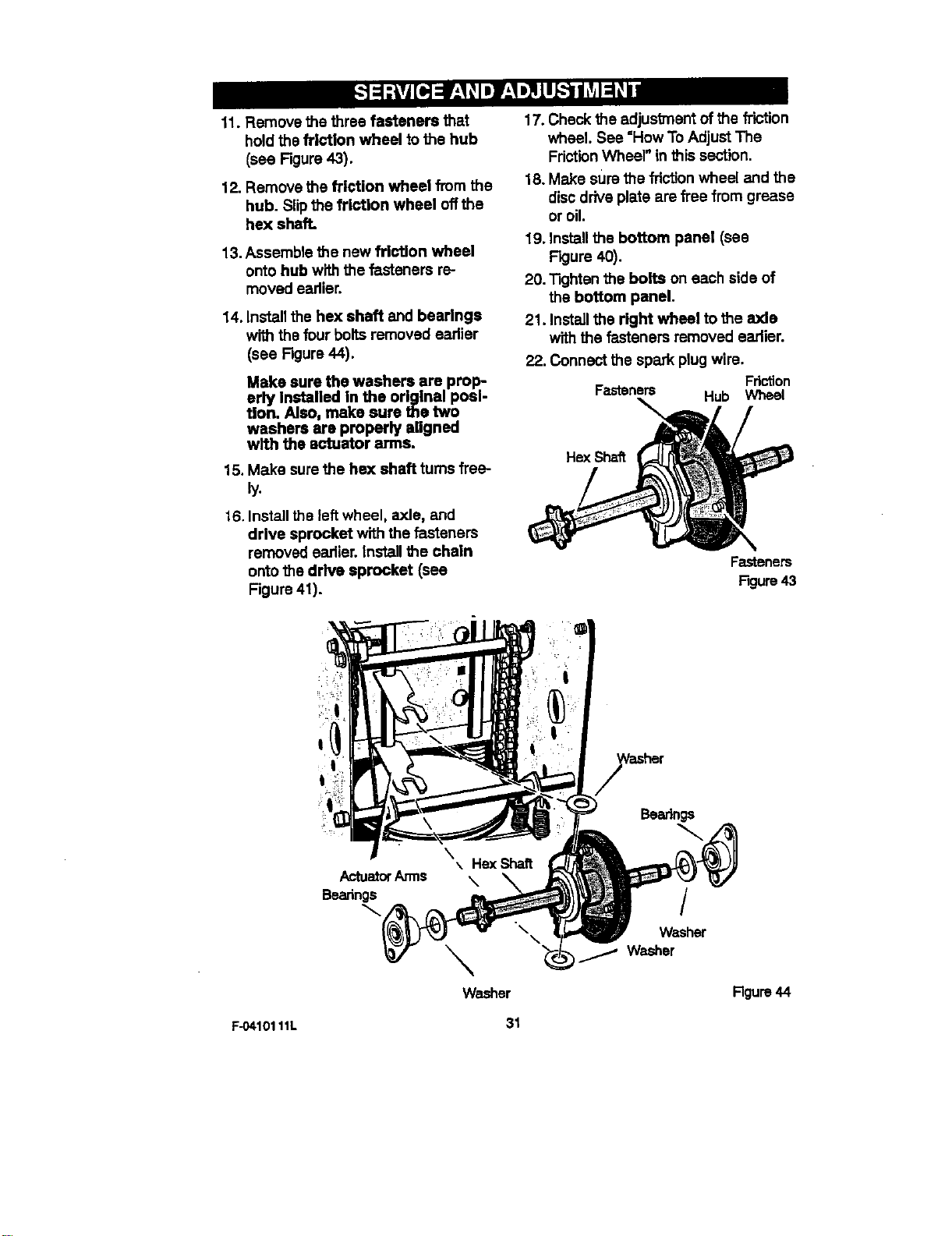
11. Remove the three fasteners that
hold the frl_ion wheel tothe hub
(see Figure 43).
12. Remove the friction wheel from the
hub. Slipthe friction wheel off the
hex shaft.
13. Assemble the new frletlon wheel
onto hub with the fasteners re-
moved earlier.
14. Install the hex shaft and bearings
with the four bolts removed eadier
(see Figure 44).
Make sure the washers are prop-
erly Installed in the original posi-
tion. Also, make sure the two
washers are properly aligned
w/th the actuator arms.
15. Make sure the hex shaft turns free-
ly.
16. Install the left wheel, axle, and
drive sprocket with the fasteners
removed earlier, install the chain
onto the drive sprocket (see
Figure 41).
17. Check the adjustment of the friction
wheel. See =How To Adjust The
FrictionWheel" in this section.
18. Make sum the frictionwheel end the
disc drive plate are free from grease
or oil.
19. Install the bottom panel (see
Figure 40).
20. "13ghtenthe bolts on each side of
the bottom panel.
21. Installthe right wheel to the axle
with the fasteners removed earlier.
22. Connect the spark plug wire.
Friction
Fasteners Hub Wheel
Fasteners
Figure43
ActuatorArms
Beadngs
\
\
Washer
/
Washer
,/ Washer
Figure 44
F..0410111L 31
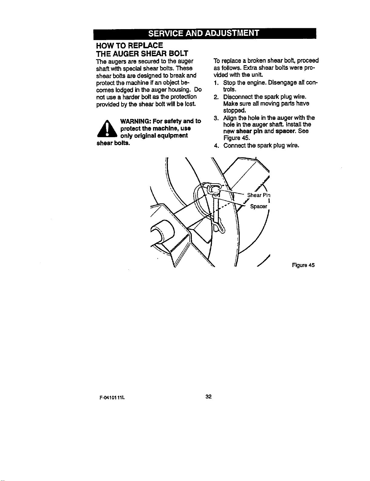
HOW TO REPLACE
THE AUGER SHEAR BOLT
The augers are secured to the auger
shaft w_ special shear bolts. These
shear bolts are designed to break and
protectthe machine ifan object be-
comes lodged in the auger housing. Do
not use a harder bolt as the protection
provided by the shear boltwill be lost.
_lb ARNING: For safety and to
protect the machine, use
only original equipment
shear bolts.
To replace a broken shear bolt, proceed
as follows. Extra shear bolts were pro-
vided with the unit.
1. Stop the engine. Disengage all con-
trois.
2. Disconnectthe spark plug wire.
Make sure all moving partshave
stopped.
3. Align the hole inthe auger with the
hole inthe auger shaft. Install the
new shear pin and spacer. See
Figure 45.
4. Connect the spark plug wire.
X
Shear Pin
/ t
Spacer
Figure 45
F-O410111L 32
_IL ARNING: Never store your
snow thrower with gasoline
In the fuel tank indoors or In
an enclosed, poorly ventilated area.
If gasoline remains In the tank,
fumes may reach an open flame,
spark or pilot light from a furnace,
water heater, clothes dryer, ciga-
rette, etc.
To prevent damage (ifsnow thrower is
not used for more than 30 days) follow
the steps below.
SNOW THROWER
1. Thoroughly clean the snow thrower.
2. lubricate all lubrication points.See
the Maintenance sacUon.
3. Be sure that all nuts, boltsand
screws are securely fastened. In-
spect all visible moving parts for
damage, breakage and wear. Re-
place if necessary.
4. Touch up all rusted or chipped paint
surfaces; sand lightlybefore paint-
ing.
5. Cover the bare metal parts of the
blower housing auger and the im-
peller with rust preventative, such
as a spray lubricant.
NOTE: Aysady checkup or tune-up by
a Sears service center is a good way of
ensuring that your snow thrower will
provide maximum performance for the
next season.
ENGINE
Gasoline must be removed or treated to
prevent gum deposits from forming in
the fuel tank, filter, hose, and carburetor
during storage. Also, during storage al-
cohol blended gasoline that uses etha-
nol or methanol (sometimes called
gasoho0 attracts water. It acts on the
gasoline to form acids which damage
the engine.
t.
2.
.
4,
5.
.
Run the engine untilthe fuel tank is
empty and the engine stops.
If you do not remove the gasoline,
use fuel stabilizer supplied with unit
or purchase Craftsman Fuel Stabi-
lizer No. 3550. Add fuel stabilizer to
any gasoline left in the tank to mini-
mize gum deposits and acids. Ifthe
fuel tank is almost empty, mix stabi-
lizer with fresh gasoline in a sepa-
rata container and add some to the
fuel tank.
Always follow the instructionson the
stabilizer container. After the stabi-
lizar is added to the fuel tank, run
the engine at least ten minutes to
allow the mixture to reach the car-
buretor.
Change the engine oil.
Remove the spark plug and pour
about 15 ml (1/2 oz) of engine oil
into the cylinder. Replace the spark
plug and crank slowly to distribute
the oil.
Store in a clean and dry area, but
NOT near a stove, furnace or water
heater which uses a pilot lightor
any device that can create a spark.
OTHER
1. Ifpossible, store your snow thrower
indoors and cover itto give protec-
tion from dust and dirt.
2. Ifthe snow thrower must be stored
outdoors, put the snow thrower on
blocks to raise it off ofthe ground.
3. Cover the snow thrower with a suit-
able protective cover that does not
retain moisture. Oo not use plastic.
IMPORTAN'I': Never cover snow
thrower while engine and exhaust areas
are stillwarm.
1:-0410111L 33
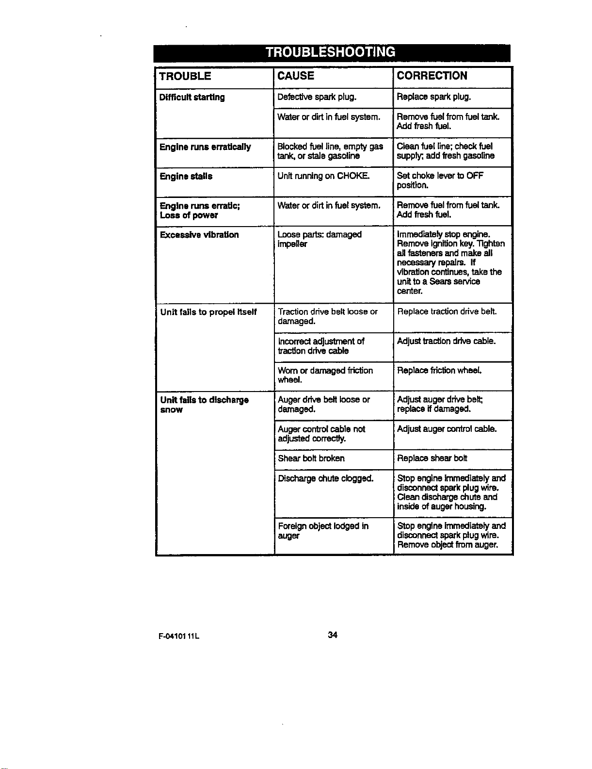
TROUBLE CORREC_ON
Difficultsta_ng Replacesparkplug.
CAUSE
Defectivesparkplug.
Waterordirtinfuelsystem.
Remove fuel TTOmfuel tank.
Add fresh fuel
Engine runs erratically Blocked fuelline, empty gas Clean fuel line; checkfuel
tank, or stale gasoline supply;,add freshgasoline
Engine stalls Unit runningon CHOKE. Set choke lever to OFF
)osition.
Engine runs ermUc; Water or dirt in fuel system. Remove fuel fromfuel tank.
:Loss of power iAdd frech fuel.
Excessive vibration Loose parts: damaged :Immediately stop engine
impeller IRemove ignitionkey.Tighten
;all fasteners and make all
necessary mpalrs. If
vibretJoncontinues, take the
unitto a Seats service
carder,
Unit falls to propel Itself Replace tractiondrive belt.
Unit fallsto discharge
snow
Tractiondrivebeltlooseor
damaged.
Incorrectadjustmentof
tractiondrivecable
Wornor damagedfriction
wheel.
Augerdriveboltlooseor
damaged.
Augercontrolcablenot
adjustedcorrectly.
Shearboltbroken
Dischargechute clogged.
Foreignobjectlodgedin
auger
Adjustb'autJondrivecable.
Replacefrictionwheel.
Adjustaugerdrivebelt;
replaceifdamaged.
Adjust auger control cable.
Replace shear bolt
Stop engine immediately and
disconnect spark plugwire.
Clean discharge chute and
insideof auger housing.
Stopengineimmediatelyand
disconnectsparkplugwire.
Removeobjectfromauger.
F-0410111L 34
('r_spageapp_ca_e_ h u.s_. and_da only,}
Sears, Roebuck and Co., U.S.A. (Sears), the California Air Resources Board
(CARB) and the United States Environmental Protection Agency (U.S. EPA)
Emission Control System Warranty Statement (Owner's Defect Warranty
Rights and Obligations)
EMISSION CONTROL WARRANTY COVERAGE IS APPUCABLE TO CERTIFIED
ENGINES PURCHASED IN CAIJFORNIA IN 1995 AND THEREAFTER, WHICH ARE
USED IN CAUFORNIA, AND TO CERTIFIED MODEL YEAR 1997 AND LATER EN-
GINES WHICH ARE PURCHASED AND USED ELSEWHERE IN THE UNITED
STATES (AND AFTER JANUARY 1, 2001 IN CANADA),
California and United States Emission Control Defects Warranty Statement
The California Air Resources Board
(CARB), U.S. EPAend Sears are pleased
to explain the Emission Control System
Warrantyon yourmodelyear2000 end lat-
er smalloff-roaders:jine(SORE). in Califor-
nia, new small off-road engines must be
des'_ned, built and equippedto meet the
State's stringent anti-smog standards.
l=lsewhareinthe United States, new non-
road, spark-ignitionengines certified for
model year 1997 end latermustmeetsimi-
lar standards set forth by the U.S. EPA.
Sears must warrant the emission control
system on your engine for the periods of
time Estedbelow,providediners has been
no abuse, neglect or improper mainte-
nance of yoursma_ off-rcad engine.
Your emission control system includes
parts such as the carburetor, air cleaner,
ignitionsystem,mufflerand catalyticcon-
verter. Also included may be connectors
and other emission related assemblies.
Where a warrantable condition exists,
Sears will repair your small off-road en-
gine at no costto you includingdiagnosis,
parts and labor.
Sears .Emission Control Defects Warranty Coverage
Small off-road engines are warranted ral- sions set forth below. If any covered part
ative to emission controlparts defects for on your engine is defective, the part will
a period of two years, subject to provl- be repaired or replaced by Seats.
Owner's Warranty Responsibilities
As the small off-road engine owner, you
are responsible for the performance of
the required maintenance listed in your
Operating end Maintenance Instructions.
Sears recommends that you retain all
your receipts covering maintenance on
your small off-road engine, but Sears
cannot deny warranty solelyfor the lack
of receiptsor for your faJureto ensure the
performance of all scheduled mainte-
nance.
As the small off-road engine owner, you
should howeverbe aware that Sears may
deny you warrantycoverage ifyour small
off-roedengine or a part hasfailed due to
abuse, neglect, impropermaintenance or
unapproved modifications.
You are responsiblefor presenting your
small off-road engine to an Authorized
Sears Service Dealer as soon as a prob-
lem exists. The undisputed warranty re-
pairs should be completed in a
reasonable amountoftime, notto exceed
30 days.
Ifyou have any questionsregardingyour
warranty rights end responsibilities,you
should contact a Sears Service Repre-
sentative at 1-800-469-4663.
The emission warranty is a defects war-
ranty. Defects are judged on normal en-
gine performance. The warranty is not
related to an in-use emission test.
Sears Emission Control Defects Warranty Provisions
The following are specificprovisionsrelativeto your EmissionControl DefectsWarranty
Coverage. It Isin additionto the Sears engine warrantyfornon-regulatsd engines found
in the Operating end Maintenance InstructJons.
F-0410111L 35
1. Warrantee Parts
Coverage under this warranty ex-
tends onlyto the parts listedbelow
(the emission control systems
parts) to the extent these parts
were present on the engine pur-
chased.
a. Fuel Metering System
Cold start enrichment sys-
tem
• Carburetor and internal
parts
Fuel Pump
b. Air InductionSystem
Air cleaner
Intake manifold
c. IgnitionSystem
Spark plug(s)
• Magneto ignitionsystem
d. Catalyst System
Catalytic converter
• Exhaust manifold
• Air injectionsystem or
pulse valve
e. Miscellaneous Items Used in
Above Systems
• Vacuum, temperature,
position,time sensitive valves
and switches
bliesCOnnectorsand assam-
2. Length of Coverage
Sears warrantsto the initialowner
and each subsequent purchaserthat
the Warrantee Parts shall be free
from defectsin materials and work-
manshipwhich caused the failure of
the Warranted Parts for a period of
two years from the date the engine
isdeliveredto a reta=lpurchaser.
3. No Charge
Repair or replacement of any War-
ranted Partwill be performed at no
charge to the owner, includingdiag-
nosticlabor which leads to the de-
terminationthat a Warrantee Pad is
defective, ifthe diagnostic work is
performed at an Authorized Sears
Service Dealer. For emissions war-
ranty service contact your nearest
Authodzee Sears Service Dealer as
listed in the =Yellow Pages" under
"Engines, Gasoline," "Gasoline En-
gines,"=Lawn Mowers," or similar
category.
4. Claims and Coverage Exclusions
Warranty claims shall be filed in ac-
cordance with me provisions ofthe
Sears Engine Warranty Policy. War-
raritycoverage shall be excluded
for failures of Warranted Parts
which are not originalSears parts
or because of abuse, neglect or im-
proper maintenance as set forth in
the Sears Engine Warranty Policy.
Sears is not liable to cover failures
ofWarrantee Parts caused bythe
use of sad-on, non-original, or mo-
difindparts.
5. Maintenance
Any Warrantee Part which is not
scheduled for replacement as re-
quiree maintenance or which is
scheduled onlyfor regular inspection
to the effect of "repair or replace as
necessary"shall be wanantee as to
defectsfor the warranty period. Any
Warrantee Pad which is scheduled
for replacement as required mainte-
nance shall be warrantee as to de-
fects onlyfor the pedod oftime up to
the firstscheduled replacement for
that part.Any replacement part that
isequivalent in performance and du-
rabilitymay be used inthe perfor-
mance of any maintenance or
repairs.The owner is responsiblefor
the performanceof all required
maintenance, as defined inthe
Sears Operating and Maintenance
Ins'ouctJons.
6. Consequential Coverage
Coverage hereunder shall extend to
the failure of any engine compo-
nants caused bythe failure of any
Warrantee Part stillunder warranty.
In_'_ USA and Canada, a 24 hourhot line,1-800.469-4663, hasa menuof pre-re-
cordedmessagesofferingyou enginem_ _icrmat_n.
F-0410111L 36
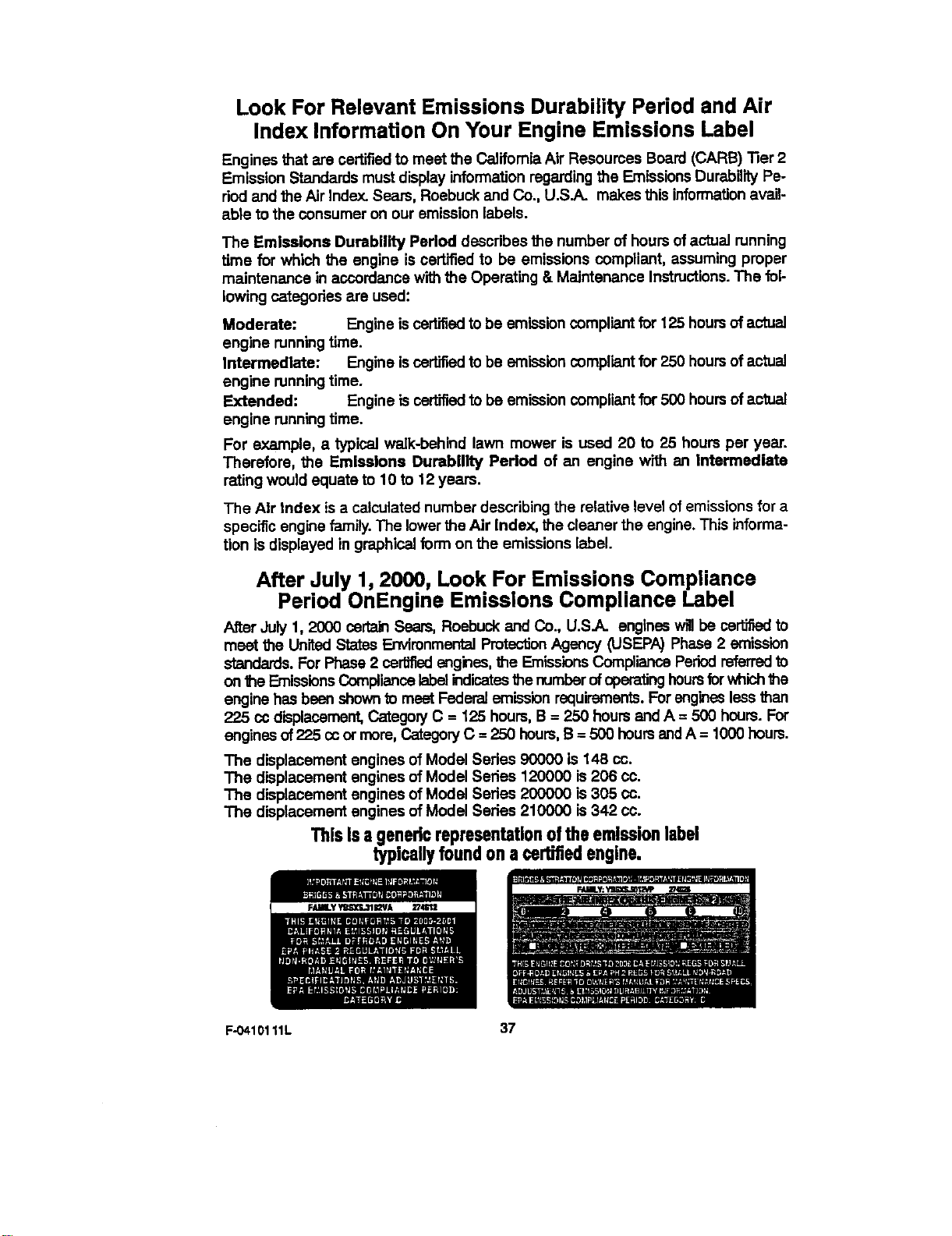
Look For Relevant Emissions Durability Period and Air
Index Information On Your Engine Emissions Label
Engines that are certifiedto meet the California Air Resources Board (CARB) "her2
Emission Standards mustdisplay informationregardingthe Emissions DurabilityPe-
riod and theAir Index. Sears, Roebuck and Co., U.S.A. makes this informationavail-
able to the consumer on our emission labels.
The Emissions Durability Period describes the number of hours ofactual running
time for which the engine is certified to be emissions compliant, assuming proper
maintenance in accordance with the Operating & Maintenance Instructions.The fol-
lowing categories are used:
Moderate: Engine iscertifiedto be emissioncompliant for 125 hours of actual
engine running time.
Intermediate: Engine iscertifiedto be emissioncompliant for 250 hoursof actual
engine runningtime.
Extended: Engine is certifiedto be emissioncompiientfor 500 hoursof actual
engine runningtime.
For example, a typical walk-behind lawn mower is used 20 to 25 hours per year.
Therefore, the Emissions Durability Period of an engine w_ an intermediate
rating would equate to 10 to 12 years.
The Air Index is a calculated number describing the relative level ofemissions for a
specific engine family.The lowerthe Air Index, the cleaner the engine.This informa-
tion is displayed in graphical form on the emissions label.
After July 1, 2000, Look For Emissions Compliance
Period OnEngine Emissions Compliance Label
After July 1, 2000 certa_ Sears, Roebuck and CO., U.S.A. engines willbe cert_led to
meet the United States EnvironmentalPmtentionAgency (USEPA) Phase 2 emission
standards. For Phase 2 certified engines, the Emissions Compliance Periodreferredto
on the EmissionsCompliancelabelindicates thenumber ofoperating hoursfor whichthe
engine has been shownto meet Federal emission requirements.Forengines lessthan
225 cc displacement,CategonJC = 125 hours, B = 250 hours and A = 500 hours. For
engines of225 ccor more, CategoryC : 250 hours,B = 500 hours end A = 1000 hours.
The displacement engines of Model Series 90000 is 148 cc.
The displacement engines of Model Series 120000 is 206 co.
The displacement engines of Modal Series 200000 is 305 co.
The displacement engines of Modal Series 210000 is 342 co.
ThisIsagenedcrepresentationoftheemlseionlabel
typicallyfoundona certifiedengine.
F-0410111L 37
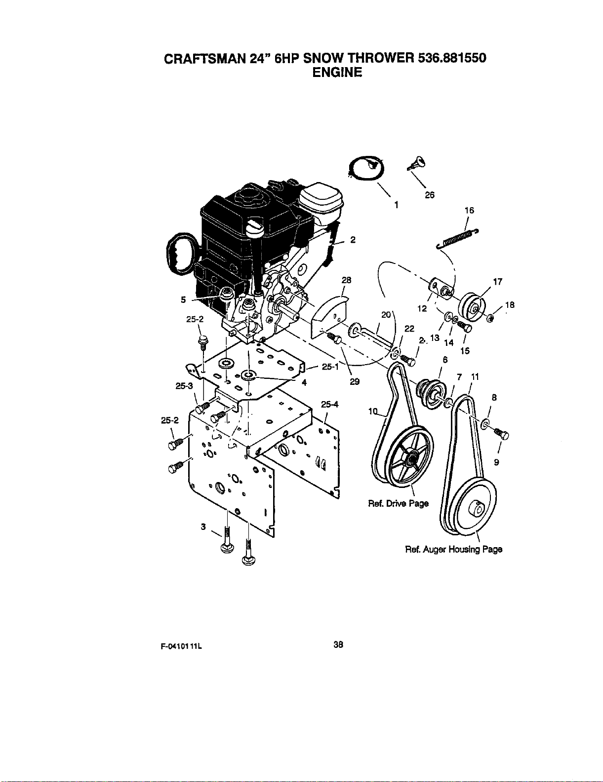
CRAFTSMAN 24" 6HP SNOW THROWER 536.881550
ENGINE
5
25-2
25-3
\
25-2
\ \o
1
28
20'
29
16
\
" '__!_
2..13 14 /
15
S
/ 7 11
8
/
/
9
3
Ref, DrivePage
Ref.Auger HousingPage
F-O410111L 3B
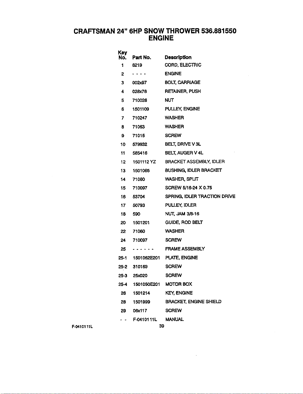
CRAFTSMAN 24" 6HP SNOW THROWER 536.881550
ENGINE
F-0410111L
Key
No. Part No. Description
1 6219 CORD, ELECTRIC
2 .... ENGINE
3 002x97 BOLT, CARRIAGE
4 028x76 RETAINER, PUSH
5 710025 NUT
5 1501109 PULLEY, ENGINE
7 710247 WASHER
8 71063 WASHER
9 71015 SCREW
10 579932 BELT,DRIVE V 3L
11 585416 BELT,AUGER V 4L
12 1501112 YZ BRACKET ASSEMBLY, IDLER
13 1501065 BUSHING, IDLER BRACKET
14 71060 WASHER, SPLIT
15 710097 SCREW 5/16-24 X 0.75
16 53704 SPRING, IDLER TRACTION DRIVE
17 50793 PULLE_, IDLER
18 590 NUT, JAM 3/8-16
20 1501201 GUIDE, ROD BELT
22 71O6O WASHER
24 710097 SCREW
25 ...... FRAME ASSEMBLY
25-1 1501062E201 PLATE, ENGINE
25-2 310169 SCREW
25-3 25xO20 SCREW
254 1501050E201 MOTOR BOX
26 1501214 KEY, ENGINE
28 1501999 BRACKET, ENGINE SHIELD
29 06xl 17 SCREW
- - F-04101 11L MANUAL
39
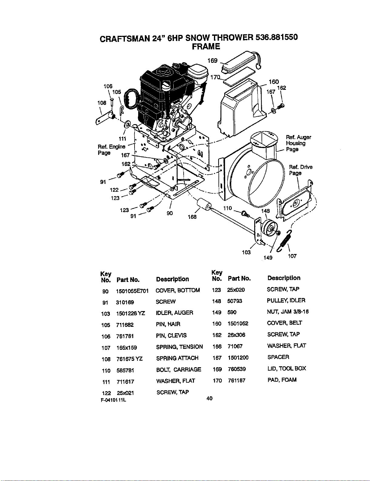
CRAFTSMAN 24" 6HP SNOW THROWER 536.881550
FRAME
169
106
/
111
Ref. Engine
Page
162_
91
/
9O
160
162
Ref.Auger
Housing
Page
Ref. Drive
Page
Key
No. Part No,
90 1501055E701
91 310169
163 1501226 YZ
105 711682
106 761761
107 165x159
108 761675 YZ
110 585781
111 711617
122 25x021
F-0410111L
103
Key
Description No. Part No.
COVER,so'r'roM 123 25x020
SCREW 148 50793
IDLER, AUGER 149 590
PIN, HAIR 160 1501052
PIN, CLEVIS 162 26x306
SPRING, TENSION 166 71067
SPRING ATrACH 167 1501200
BOLT, CARRIAGE 169 760539
WASHER, FLAT 170 761187
SCREW, TAP
4O
149 107
Description
SCREW,TAP
PULLEY,IDLER
NUT,JAM 3/8-16
COVER,BELT
SCREW,TAP
WASHER,FLAT
SPACER
LID, TOOLBOX
PAD,FOAM
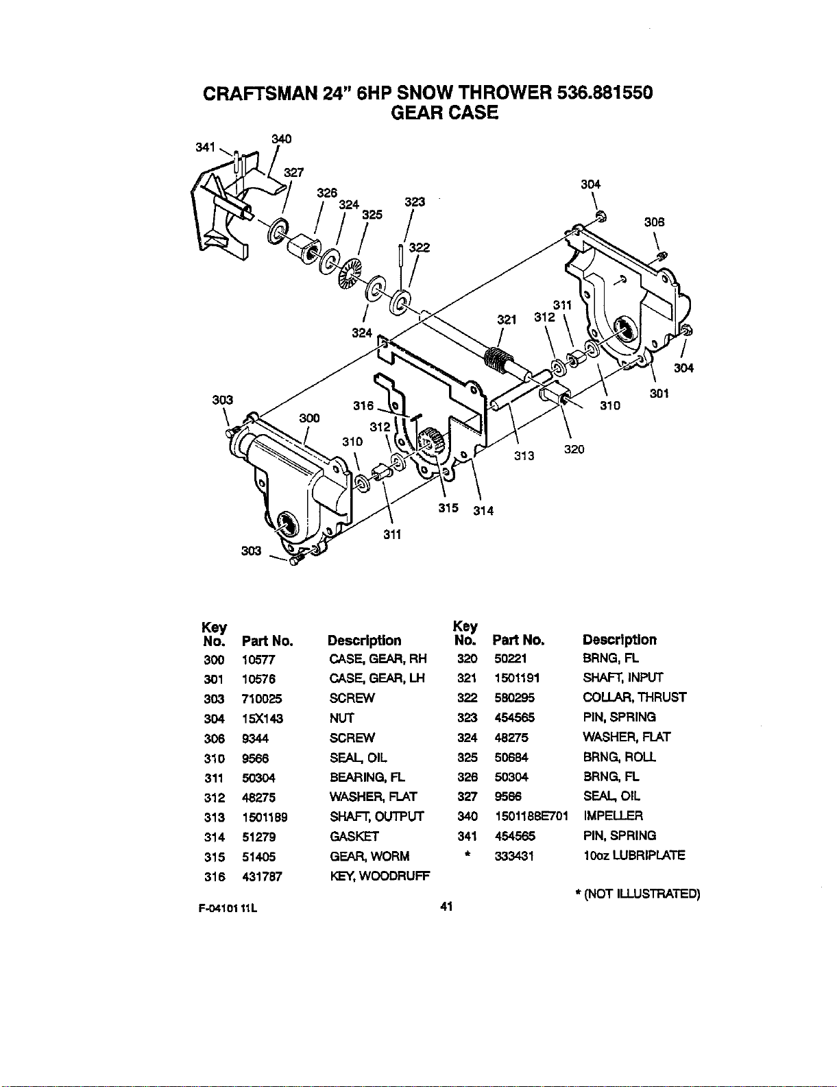
CRAFTSMAN 24" 6HP SNOW THROWER 536.881550
GEAR CASE
340
327
326
324
325
/
324
304
303
\
313
310
320
3O4
301
3O3
311
315 314
Key
No. Part No.
300 10577
301 10576
303 710025
304 15X143
306 9344
310 9566
311 50304
312 48275
313 1501189
314 51279
315 51405
316 431787
F-O4101 11L
Key
Description No. Part No.
CASE,GEAR,RH 320 50221
CASE, GEAR,LH 321 1501191
SCREW 322 580295
NUT 323 454565
SCREW 324 48275
SEAL,OIL 325 50684
BEARING,FL 326 50304
WASHER,FLAT 327 9566
SHAFT,OUTPUT 340 1501183E701
GASKET 341 454565
GEAR,WORM * 333431
KEY,WOODRUFF
41
Description
BRNG,FL
SHAFT,INPUT
COLLAR,THRUST
PIN,SPRING
WASHER,FLAT
BRNG. ROLL
BRNG, FL
SEAL.OIL
IMPELLER
PIN,SPRING
10ozLUBRIPLATE
* (NOT ILLUSTRATED)
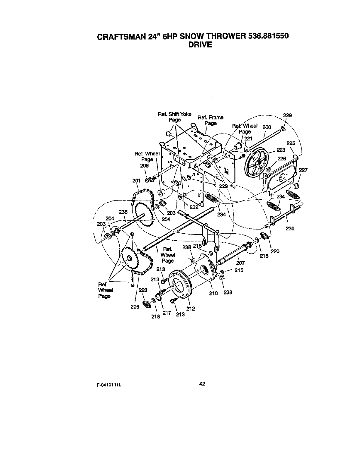
CRAFTSMAN 24" 6HP SNOW THROWER 536.681550
DRIVE
Page
206
\
201
\
R_. Shift Yoke
Page Ref. Frame f--_-_, 229
Page R/e,f:_/heel 200
225 \
\/
227
/
F
/
I 204
2O3
Ref.
Wheel
Page
236
208
218
212
213
218
207
/ 215
\
210 238
\
22O
F-04101 11L 42
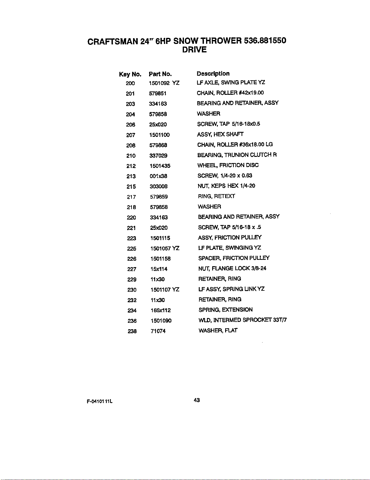
CRAFTSMAN 24" 6HP SNOW THROWER 536.881550
DRIVE
Key No. Part No.
200 1501o92 YZ
201 579851
203 334163
204 579858
206 25x020
207 1501100
208 579868
210 337029
212 1501435
213 001x38
215 303008
217 579859
218 579858
220 334163
221 25_d)20
223 1501115
225 1501057 YZ
2_26 1501158
227 15X114
229 11x30
230 1501107 YZ
232 11X30
234 165x112
236 1501090
238 71074
Description
LF AX]_E, SWING PLATE YZ
CHAIN, ROLLER #42x19.00
BEARING AND RETAINER, ASSY
WASHER
SCREW, TAP 5/16-18x0.5
ASSY, HE)( SHAFT
CHAIN, ROLLER #36x18.00 LG
BEARING, TRUNION CLUTCH R
WHEEL, FR|CT]ON DISC
SCREW, 1/4-20 x 0.63
NU'_,I<]EPSHE)( I/4-20
RING, RETEXT
WASHER
BEARING AND RETAINER, ASSY
SCREW, TAP 5/16-18 x .5
ASSY, FRICTION PULLEY
LF PLATE, SWINGING YZ
SPACER, FRIC"i3ON PULLEY
NUT, FLANGE LOCK 3/8-24
RETAINER, RING
LF ASSY, SPRING LINK YZ
RETAINER, RING
SPRING, EXTENSION
WLD, INTERMED SPROCKET 33T/7
WASHER, FLAT
F-0410111L 43
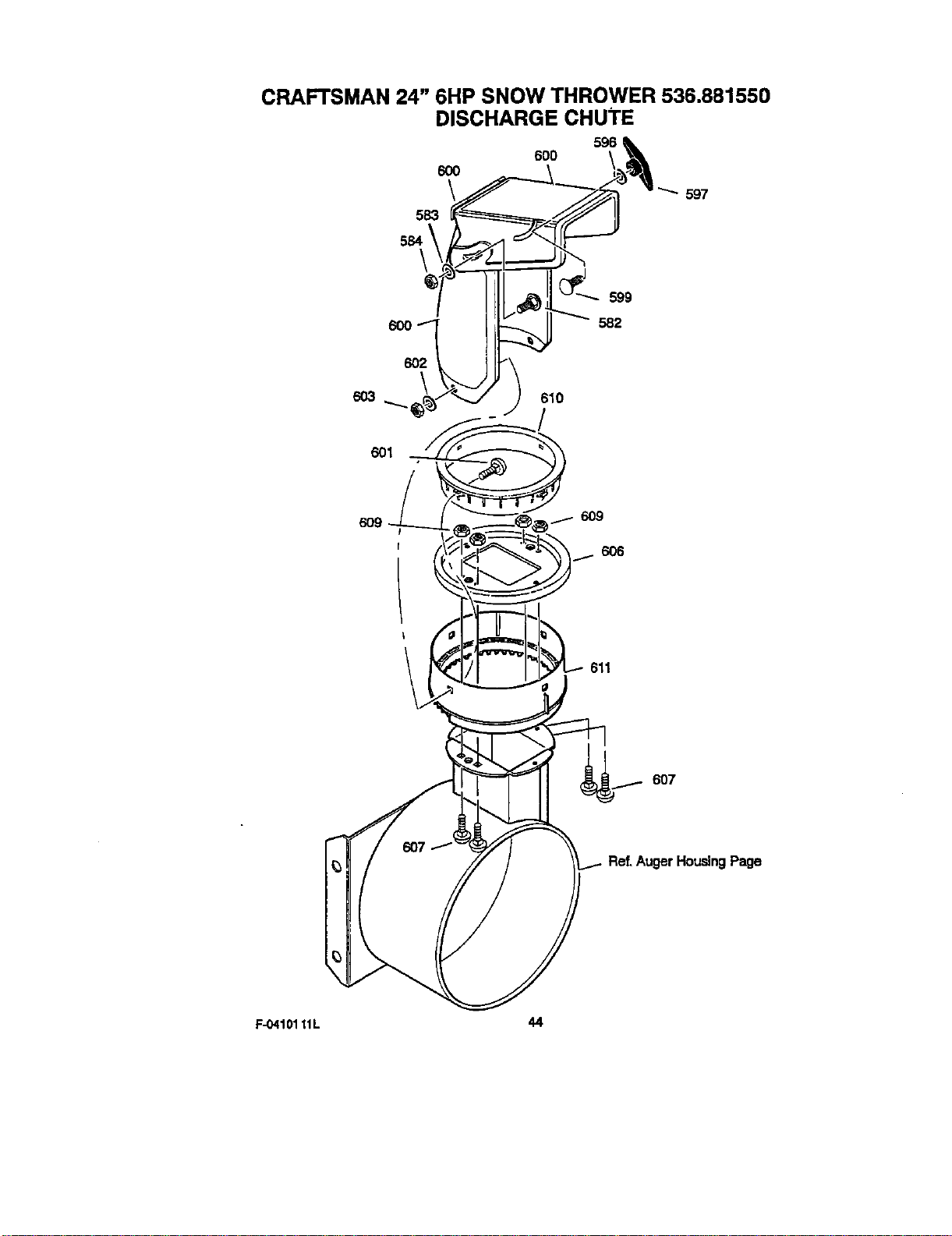
CRAFTSMAN 24" 6HP SNOW THROWER 536.881550
DISCHARGE CHUTE
6O3
597
601
609
/ 6O9
6O6
f
611
6O7
Ref.AugerHousingPage
F-0410111L 44
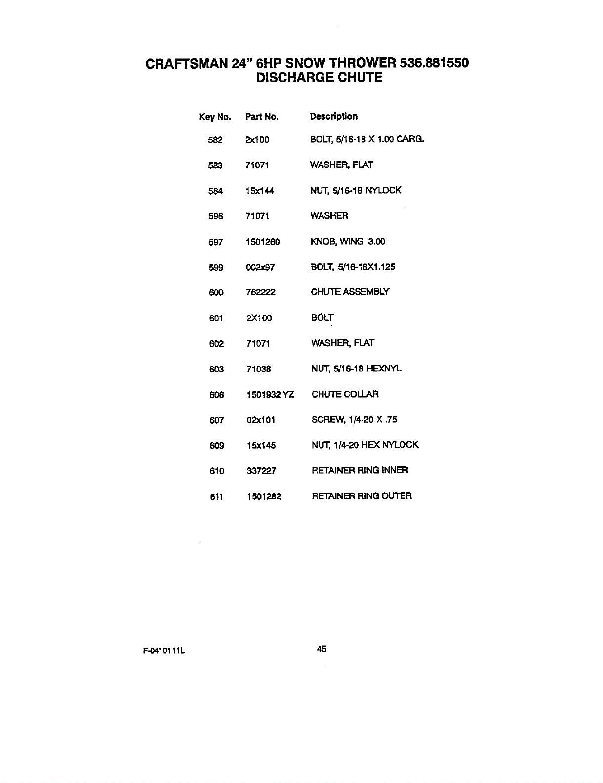
CRAFTSMAN 24" 6HP SNOW THROWER 536.881550
DISCHARGE CHUTE
Key No. Part No. Description
582 2x100 BOLT,5/16-18X 1.00CARG.
583 71071 WASHER,FLAT
584 15x144 NUT,5/16-18 NYLOCK
596 71071 WASHER
597 1501260 KNOB,WING 3.00
599 002x97 BOLT,5/16-18X1.125
600 762222 CHUTEASSEMBLY
601 2X100 BOLT
602 71071 WASHER,FLAT
603 71038 NUT, 5/16-18 HEXNYL
606 1501932YZ CHUTE COLLAR
607 02x101 SCREW, 1/4-20 X .75
609 15x145 NU'_,1/4-20 HE)( NYLOCK
610 337227 RETAINERRINGINNER
611 1501282 RETAINERRINGOLrT'ER
F-0410111L 45
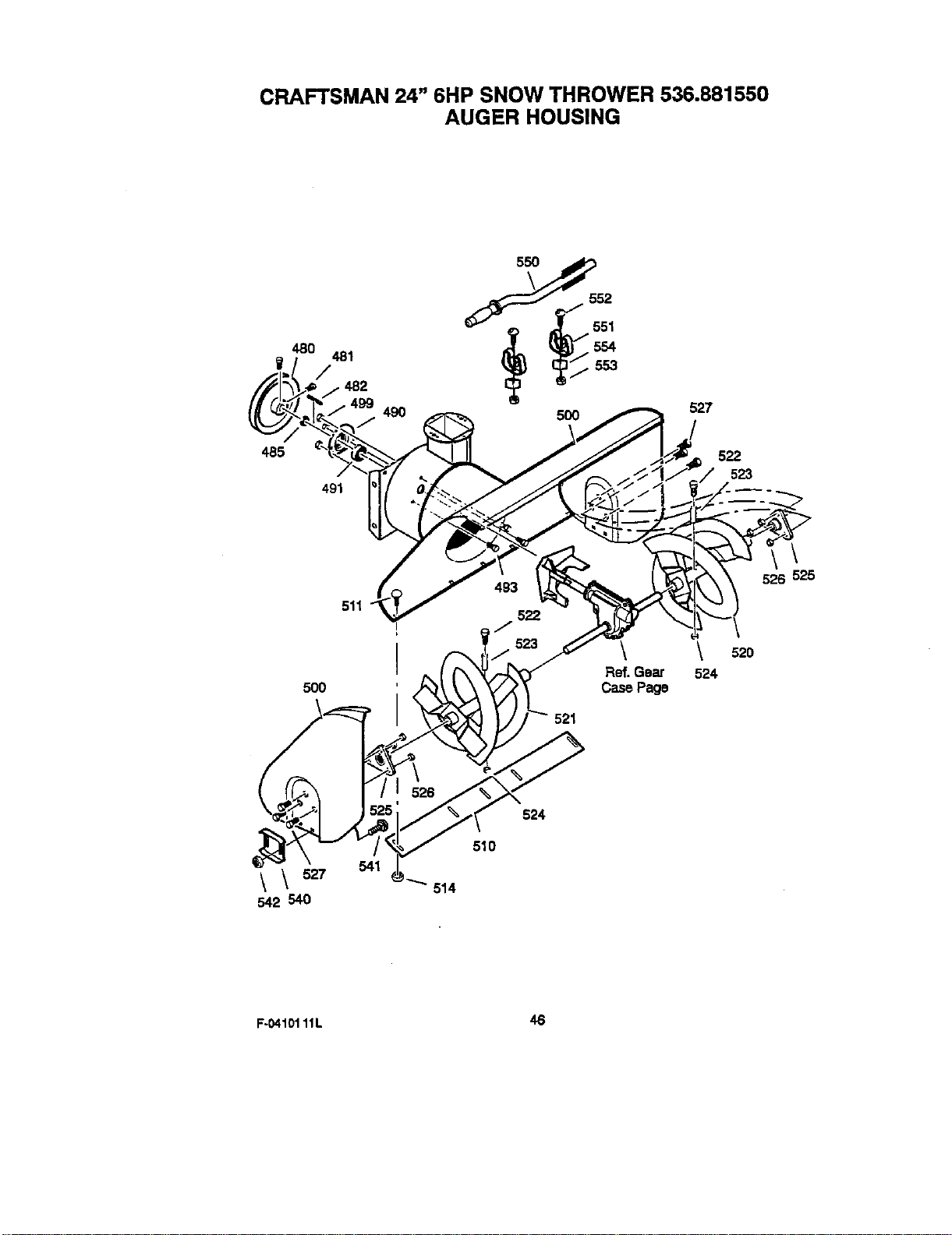
CRAFTSMAN 24" 6HP SNOW THROWER 536.881550
AUGER HOUSING
485
480
481
/
491
553
49O 5OO
527
522
523
511
\
526 525
500
\
Ref. Gear
Case Page
521
520
524
\\_z7
542 540
524
510
F-04101 11L 46
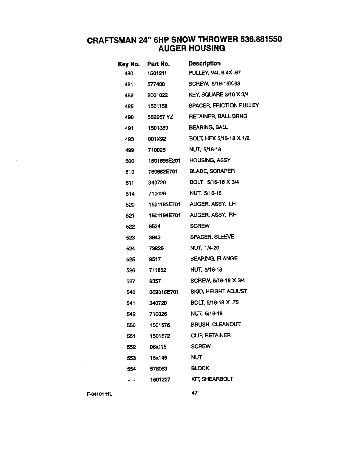
CRAFTSMAN 24" 6HP SNOW THROWER 536.881550
AUGER HOUSING
Key No. Part No. Description
480 1501211 PULLEY,V4L8.4X .67
481 577400 SCREW, 5/16-18_63
482 2001022 I<_-_,SQUARE3/16 X 3/4
485 1501158 SPACER,FRICTIONPULLEY
490 582957YZ RETAINER,BALLBRNG
491 1501389 BEARING,BALL
493 001X92 BOLT,HEX5/16-18 X !/2
499 710026 NUT, 5/16-18
500 1501696E201 HOUSING,ASSY
510 760662E701 BLADE,SCRAPER
511 340720 BOLT, 5/16-18X 3/4
514 710026 NUT, 5/16-16
520 1501195E701 AUGER,ASSY, LH
521 1501194E701 AUGER,ASSY, RH
522 9524 SCREW
523 3943 SPACER,SLEEVE
524 73826 NUT, 1/4-20
525 9517 BEARING,FLANGE
526 711862 NUT, 5/16-18
527 9357 SCREW, 5/16-18X 3/4
540 309016E701 SKID,HEIGHTADJUST
541 340720 BOLT,5/16-18 X .75
542 710026 NUT, 5/16-18
550 1501576 BRUSH,CLEANOUT
551 1501672 CLIP,RETAINER
552 06xl15 SCREW
553 15xl46 NUT
554 578O63 BLOCK
- - 1501227 KIT,SHEARBOLT
F-0410111L 47
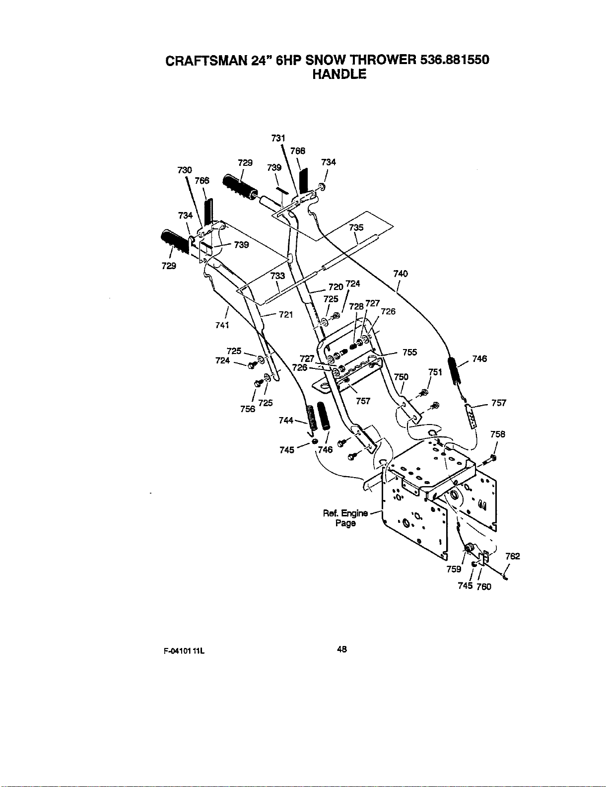
CRAFTSMAN 24" 6HP SNOW THROWER 536.881550
HANDLE
73O
729
731
766
734
/
729
74O
/
741
746
756 725
757
758
/
759
745 760
762
F-04101 11L 48
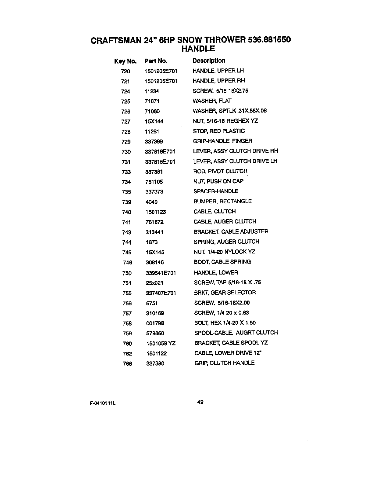
CRAFTSMAN 24" 6HP SNOW THROWER 536.881550
HANDLE
Key No. Part No.
720 1501205E701
721 1501206E701
724 11234
725 71071
726 71050
727 15X144
728 11261
729 337399
730 337816E701
731 337815E701
733 337381
734 761105
735 337373
739 4049
740 1501123
741 761872
743 313441
744 1673
745 15X145
746 308146
760 339541 E701
751 25x021
755 337407E701
756 6751
757 310169
758 001798
759 579B60
760 1501059YZ
762 1501122
766 337380
Description
HANDLE,UPPER LH
HANDLE,UPPER RH
SCREW, 5/16-18X2.75
WASHER,FLAT
WASHER,SPTLK.31X.58X.08
NUT,5/16-18 REGHEXYZ
STOP,RED PLASTIC
GRIP-HANDLEFINGER
LEVER,ASSY CLUTCHDRIVERH
LEVER,ASSYCLUTCHDRIVELH
ROD,PIVOT CLUTCH
NUT,PUSH ONCAP
SPACER-HANDLE
BUMPER,RECTANGLE
CABLE,CLUTCH
CABLE,AUGERCLUTCH
BRACKET,CABLEADJUSTER
SPRING,AUGERCLUTCH
NUT,1/4-20 NYLOCKYZ
BOOT,CABLESPRING
HANDLE,LOWER
SCREW,TAP 5/16-18 X .75
BRKT,GEARSELECTOR
SCREW, 5/16-18X2.00
SCREW, 1/4-20x 0.63
BOLT,HEX 1/4-20X 1.50
SPOOL-CABLE,AUGRTCLUTCH
BRACKET,CABLESPOOLYZ
CABLE,LOWER DRIVE12"
GRIP,CLUTCHHANDLE
F-O410111L 49
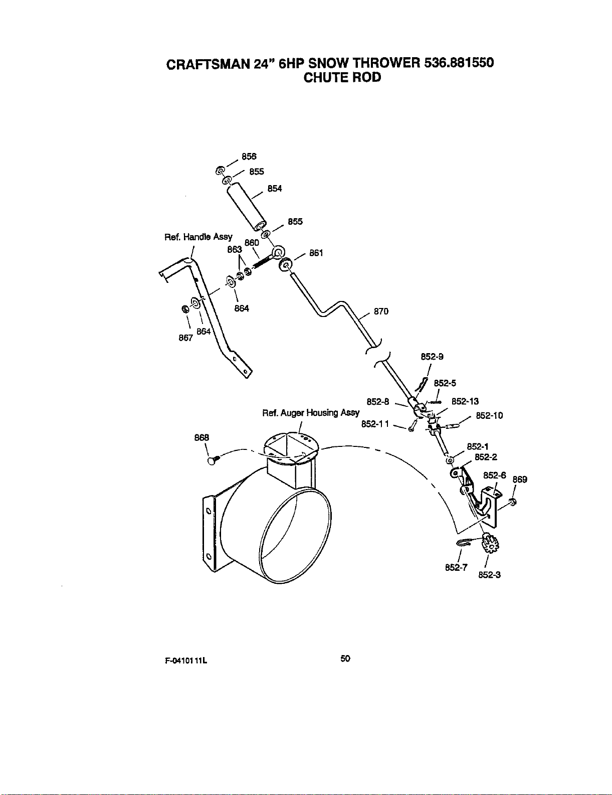
CRAFTSMAN 24" 6HP SNOW THROWER 536.881550
CHUTE ROD
856
855
Ref. Hanole Assy
\
867
868
855
j 851
Ref.AugerHousingAssy
870
852-9
/
852-5
852-8 852-13
j 852-10
852-1
852-2
869
/
/ /
852-7
852-3
F-O410111L 50
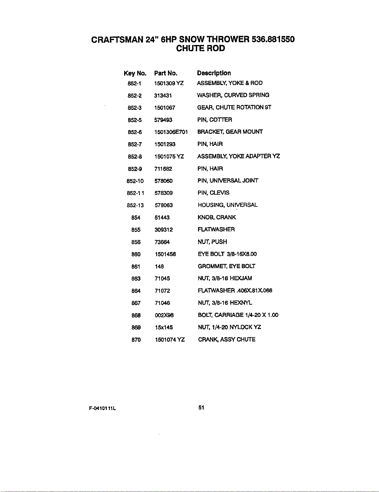
CRAFTSMAN 24" 6HP SNOW THROWER 536.881550
CHUTE ROD
Key No. Part No.
852-1 1501309 YZ
852-2 313431
852-3 1501067
852-5 579493
852-6 1501306E701
852-7 1501293
852-5 1501075 YZ
852-9 711682
852-10 578060
852-11 578309
852-13 578063
854 51443
855 309312
856 73664
860 1501456
861 148
863 71045
864 71072
867 71046
868 002X98
869 15x145
570 1501074 YZ
Description
ASSEMBLY, YOKH & ROD
WASHER, CURVED SPRING
GEAR, CHUTE ROTATION 91"
PiN, COTTER
BRACK_-T, GEAR MOUNT
PIN, HAIR
ASSEMBLY, ¥OK_ ADAPTER 'YZ
PIN, HAIR
PIN, UNIVERSAL JOINT
PIN, CLEVIS
HOUSING, UNIVERSAL
KNOB, CRANK
FLATWASHER
NUT, PUSH
EYE BOLT 3/8-16X6.00
GROMME'_, EYE BOLT
NUT, 3/8-16 HEXJAM
FLATWASHER .406X.81 X.066
NUT, 3/5-16 HEX]qYL
BOLT, CARRIAGE 1/4-20 X 1.00
NUT, 1/4-20 NYI..OCK YZ
CRANK, ASSY CHUTE
F-O410111L 51

CRAFTSMAN 24" 6HP SNOW THROWER 536.881550
SHIFT YOKE
796
792
\ 801
791
80O
814
8O2
/
812
813
F-04101 11L
Key No.
790
791
792
796
8oo
801
8o2
812
813
814
Part No,
336702E701
302628
73826
331624
760564
302628
73826
1501085YZ
11x30
579944
Description
ROD, SHIFT
SCREW, 1/4-20)(.75
NUT, 1/4-20
KNOB,SLIP
LEVER,SPRING
SCREW, 1/4-20)(.75
NUT, 1/4-20
ROD ASSY.,SPEEDSELECT
RETAINER,RING
BEARING,FLANGED
52
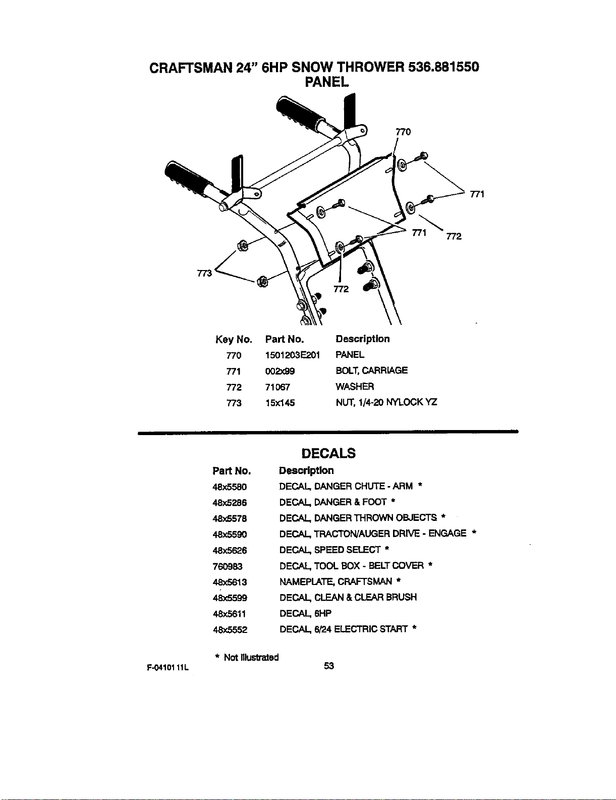
CRAFTSMAN 24" 6HP SNOW THROWER 536.881550
PANEL
770
771
772
772
Key No. Part No. Description
770 1501203E201 PANEL
771 002:<99 BOLT.CARRIAGE
772 71O67 WASHER
773 15x145 NUT, 1/4-20 NYLOCK YZ
Part No.
48x5580
48,/,5286
48x5578
48x5590
48x5626
760983
48x5613
48x5599
48:<5611
48x5552
DECALS
Description
DECAL,DANGERCHUTE - ARM *
DECAL,DANGER&FOOT *
DECAL DANGERTHROWNOBJECTS *
DECAL,TRACTON/AUGERDRIVE - ENGAGE *
DECAL,SPEEDSELECT *
DECAL,TOOL BOX- BELTCOVER *
NAMEPLATE,CRAFTSMAN*
DECAL,CLEAN&CLEARBRUSH
DECAL 6HP
DECAL,6/24 ELECTRICSTART *
* Not llluslmted
F-0410111L 53
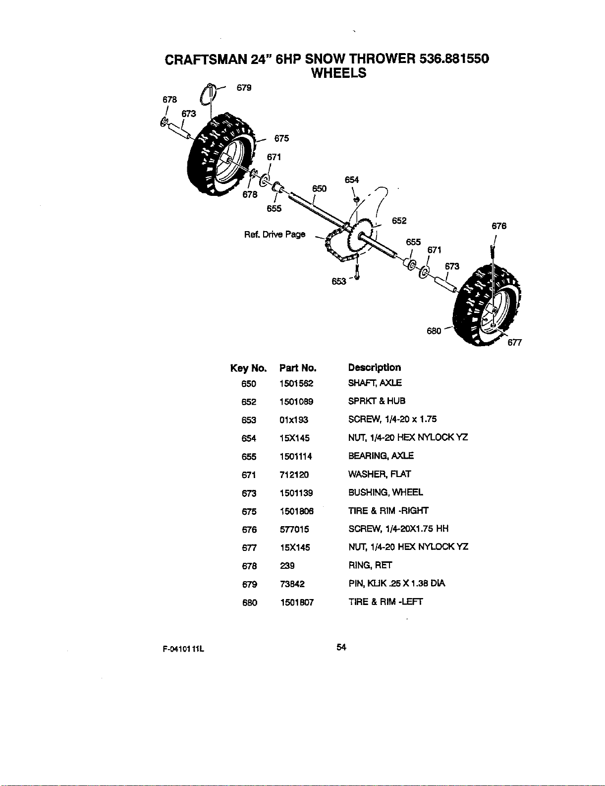
CRAFTSMAN 24" 6HP SNOW THROWER 536.881550
WHEELS
678
/
679
673
675
671
654
678 650 . F_
655
Ref. Drive Page
652
676
Key No. Part No.
650 1501562
652 1501089
653 01x193
654 15X145
655 1501114
671 712120
673 1501139
675 1501806
676 577015
677 15X145
678 239
679 73842
680 1501807
Description
SHAF'_,AXLE
SPRKT&HUB
SCREW,1/4-20x 1.75
NUT,1/4-20 HEXNYLOCKYZ
BEARING,AXLE
WASHER,FLAT
BUSHING,WHEEL
TIRE & RIM -RIGHT
SCREW,1/4-20X1.75 HH
NUT,1/4-20HEX NYLOCKYZ
RING,RET
PiN,KLIK.25X 1.38DIA
TIRE &RIM -LEFT
F-04101 11L 54

F-O410111L 55
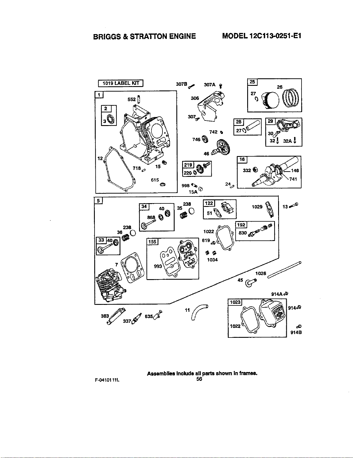
BRIGGS & STRATI'ON ENGINE MODEL 12C113-0251-E1
I 1019 LABEL KIT I
_2 0
615
307B_ 307A
_7_,_
742
998
15A _'_
I _,___- 1,o
Assemblies Includo all parts shown in frames.
F-.0410111L 56
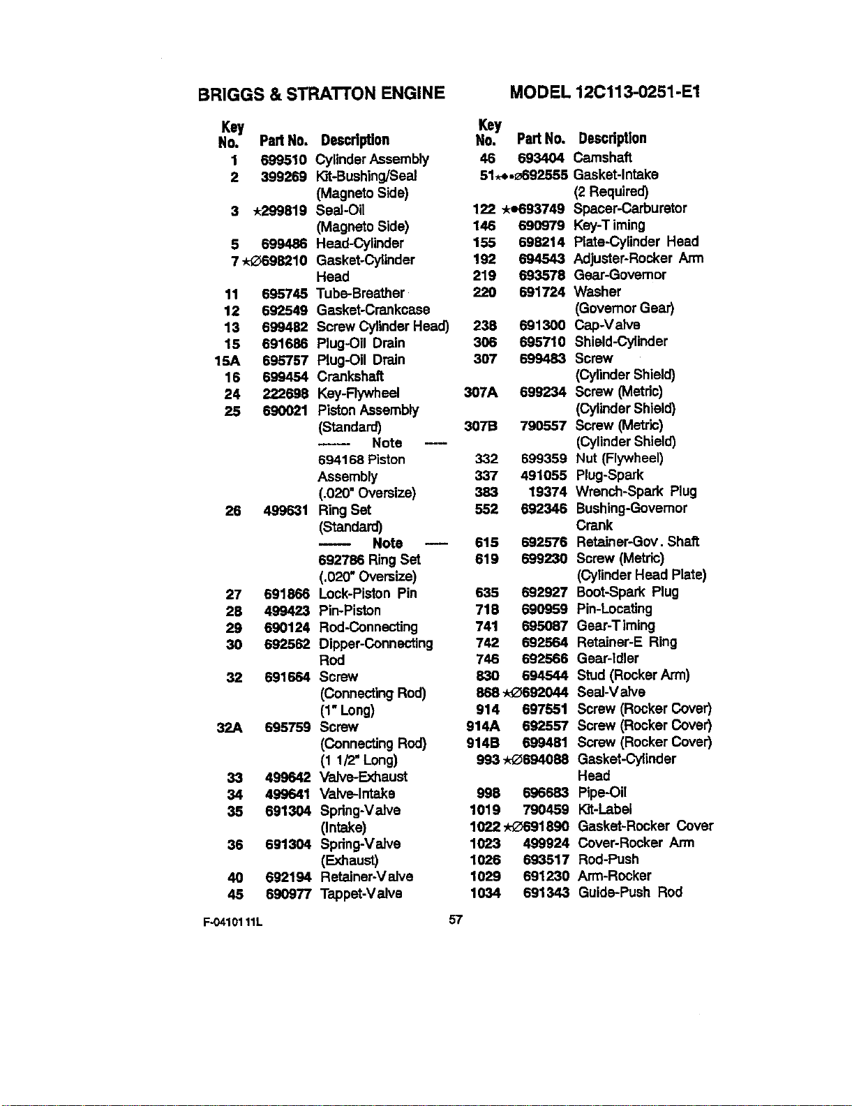
BRIGGS & STRATTON ENGINE
MODEL 12Cl13-0251-E1
Key
No. Part No. Descdption
1 699510 Cylinder Assembly
2 399269 Kit-Bushing]Seal
(Magneto Side)
3 ,299819 Seal-Oil
(Magneto Side)
5 699486 Head-Cylinder
7 -,,_-_698210 Gasket-Cylinder
Head
11 695745 Tube-Breather
12 692549 Gasket-Crankcase
13 699482 Screw Cylinder Head)
15 691686 Plug-Oil Drain
15A 695757 Plug-OU Drain
16 699454 Crankshaft
24 222698 Key-Rywheel
25 690021 Piston Assembly
(Standard)
----- Note ---
694168 Piston
Assembly
(.020" Oversize)
26 499631 Ring Set
(Standard)
-- Note --
692763 Ring Set
6020" Oversize)
27 691866 Lock-Piston Pin
28 499423 Pin-Piston
29 690124 Rod-Connecting
30 692562 Dipper-Connecting
Rod
32 691664 Screw
(Connecting Rod)
(1" Long)
32A 695759 Screw
(Connecting Rod)
(1 1/2" Long)
33 499642 Valve-Exhaust
34 499641 Valve.-Intake
35 691304 Spring-Valve
(Intake)
36 691304 Spring-Valve
(Exhaust)
40 692194 Retalnar-Valve
45 690977 Tappet-Valve
Key
No. Part No. DescdpUon
45 693404 Camshaft
51,-_._692555 Gasket-Intake
(2 Required)
122 ,e693749 Spacer-Carburetor
145 690979 Key-Timing
155 698214 Plate-Cylinder Head
192 694543 Adjustar-Rocker Ann
219 693578 Gear-Governor
220 691724 Washer
(Governor Gear)
238 691300 Cap-Valve
306 695710 Shield-Cylinder
307 699483 Screw
(Cylinder Shield)
337A 699234 Screw (Metdc)
(Cylinder Shield)
3079 790557 Screw (Metric)
(Cylinder Shield)
332 699359 Nut (Flywheel)
337 491055 Plug-Spark
363 19374 Wrench-Spark Plug
552 692346 Bushing-Governor
Crank
615 692576 Retainer-Gov. Shaft
619 699230 Screw (Metric)
(Cylinder Head Plate)
635 692927 Boot-Spark Plug
719 690959 Pin-Locating
741 695087 Gear-Timing
742 692564 Retalner-E Ring
746 692566 Gear-Idler
830 694544 Stud (Rocker Arm)
868 -_692044 Seal-Valve
914 697551 Screw (Rocker Cover)
914A 692557 Screw (Rocker Cover)
914B 559481 Screw (Rocker Cover)
993 -x_554063 Gasket-Cylinder
Head
998 696683 Pipe-Oil
1019 790459 I_t-Label
1022,O691890 Gasket-Rocker Cover
1023 499924 Cover-Rocker Arm
1026 693517 Rod-Push
1029 691230 Arm-Rocker
1034 691343 Guide-Push Rod
F-0410111L 57
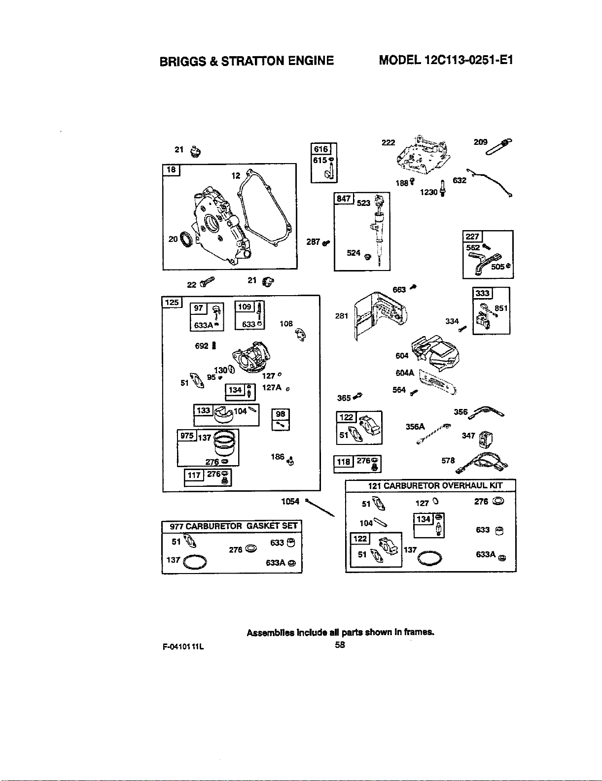
BRIGGS & STRAI"rON ENGINE MODEL 12C113-0251-E1
12
287 _.
108
s92I
,7_._.1137
276Q 186_
3ss_
121 CARBURETOR OVERHAUL KIT
977 CARBURETOR GASKET SET
sl_ 276_ 633_
137 O 633A
51%
104_
51 _
127 _ 2/'6 _)
137 O _3A _
Assemblies Include all parts shown In frames,
F-0410111L 5B
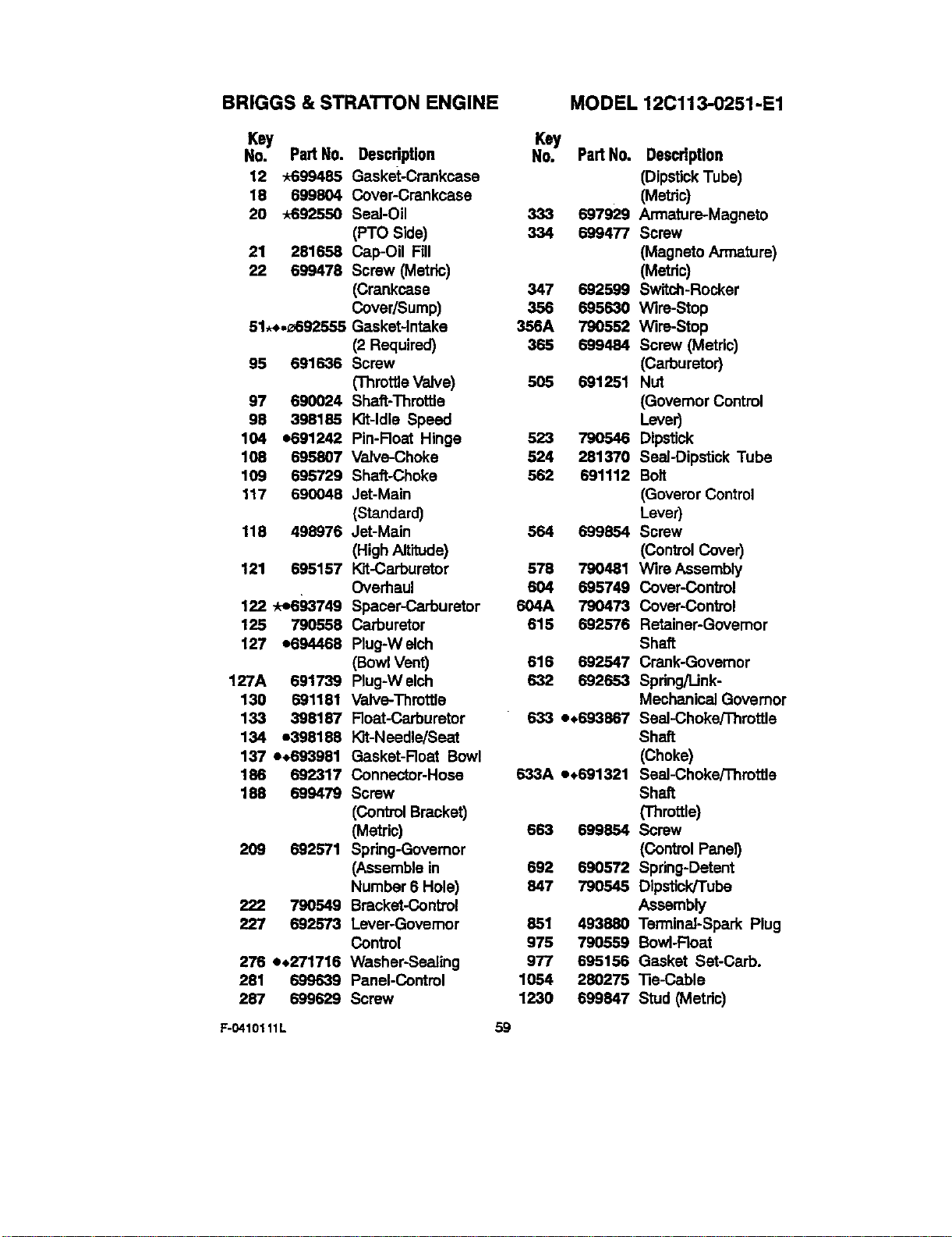
BRIGGS & STRATTON ENGINE MODEL 12Cll 3-0251 -El
Key
No. PartNo. Descdption
12 -k699485 Gasket-Crenkcase
18 699804 Cover-Crankcase
20 -x692550 Seal-Oil
(PTO Side)
21 281658 Cap-Oil Fill
22 699478 Screw (Metric)
(Crankcase
Cover/Sump)
51._._692555 Gasket-Intake
(2 Required)
95 691636 Screw
(ThrottleValve)
97 690024 Shaft-Throttle
98 398185 I_t-ldle Speed
104 o691242 Pin-Float Hinge
108 695807 Valve-Choke
109 695729 Shaft-Choke
117 690048 Jet-Main
(Standard)
118 498976 Jet-Main
(High Altitude)
121 695157 I_t-Carburstor
Overhaul
122 -ke693749 Spacer-Carburetor
125 790868 Carburetor
127 o694468 Plug-Welch
(BowlVent)
127A 691739 Plug-Welch
130 691181 Valve-Throttle
133 398187 Float-Carburetor
134 e398186 I_Jt-Needle/Seat
137 e_693981 Gasket-Roat Bowl
186 692317 Connector-Hose
186 699479 Screw
(Control Bracket)
(Metric)
209 692571 Spdng-Govemor
(Assemble in
Number 6 Hole)
222 790549 Bracket-Control
227 692573 Lever-Governor
Control
276 e.271716 Washer-Sealing
261 699639 Panel-Control
287 699629 Screw
Key
No. Part No. Description
(DipstickTube)
(Metric)
333 697929 Armature-Magneto
334 699477 Screw
(Magneto Armature)
(Metric)
347 692599 Switch-Rocker
356 865630 Wire-Stop
386A 790552 Wire-Stop
386 699484 Screw (Metric)
(Carburetor)
505 691251 Nut
(Governor Control
Lever)
523 790546 Dipstick
524 281370 Seal-Dipstick Tube
562 691112 Bolt
(Goveror Control
Lever)
564 699854 Screw
(Con_'ol Cover)
578 790481 Wire Assembly
604 695749 Cover-control
604A 790473 Cover-Control
615 692576 Retainer-Governor
Shaft
616 692547 Crenk-Govemor
632 692653 Spring/Unk-
Mechanical Governor
633 e,693867 Seal-Choke/Throttle
Shaft
(Choke)
633A =,691321 Seal-Choke/Throttle
Shaft
('rhmtUe)
663 869854 Screw
(ControlPanel)
692 690572 Spring-Detent
847 790545 Dipst_k/Tube
Assembly
851 493880 Terminal-Spark Plug
975 790869 Bowl-Float
977 695156 Gasket Set-Carb.
1054 280275 Tie-Cable
1230 699847 Stud (Metric)
F-0410111L 59
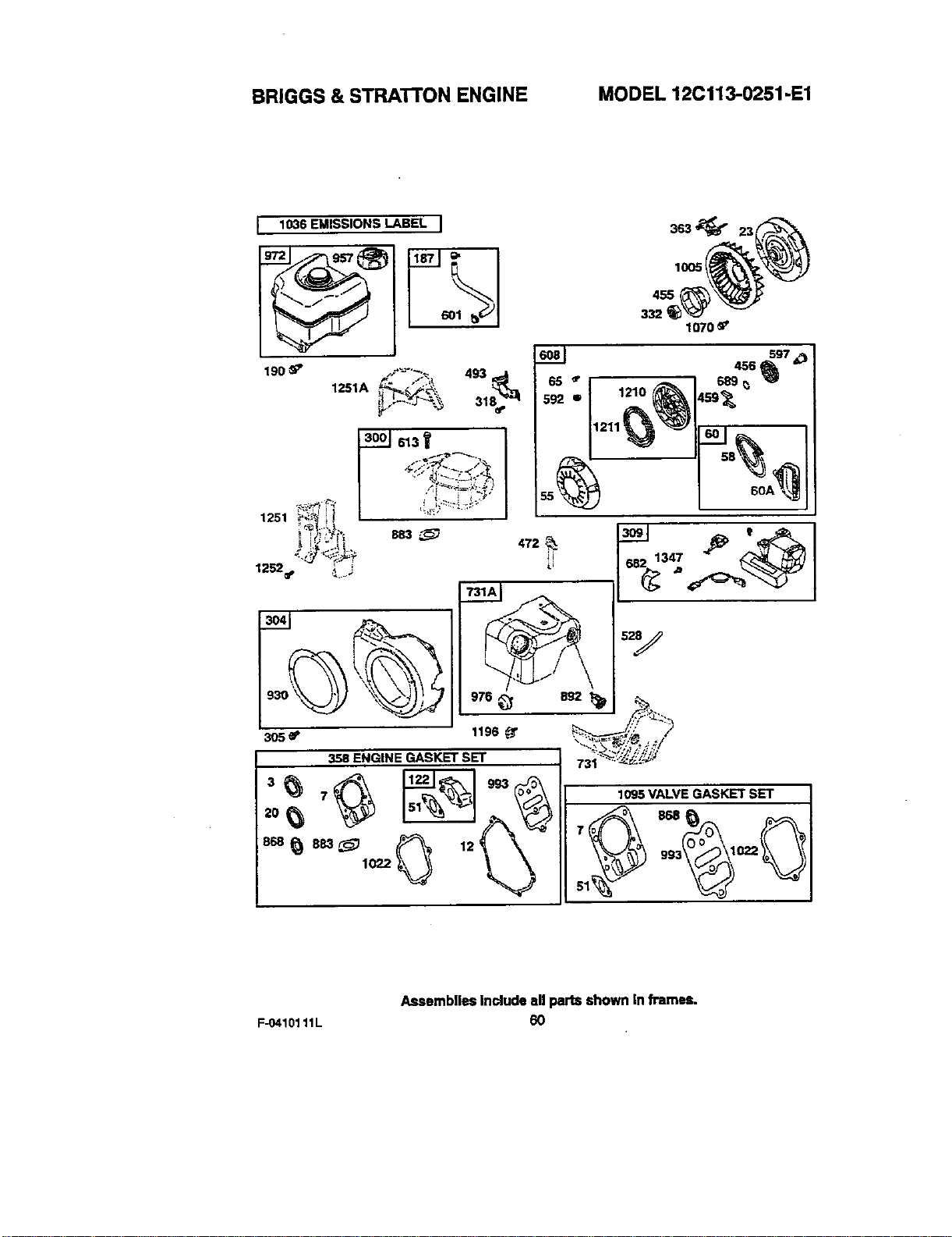
BRIGGS & STRATTON ENGINE MODEL 12C113-0251 -El
I 1036 EMISSIONS LABEL I
3_.J613Y
i"+/+;++'+ sBs,_
• ;
1252_ _..j
i
305 eP
493 6_ I 65
31 592
i ] ,
1196 _" ""_'_ _{'N 4.,"/
•,.,.y?/,;?//_1
731_._._ _'
1005
455
332 I
1070 _'
697
i ++
20_3_ 7_ _2_'" 993 1095VALVEGASKE_SET658_"_'L
Assemblies Include all parts shown In frames.
F-0410111L 60
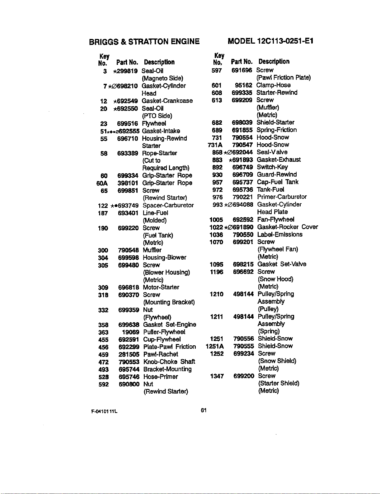
BRIGGS & STRATrON ENGINE
Key
No. Part No. Descdption
3 -k299619 Seal-Oil
(Magneto Side)
7 _-0698210 Gasket-Cylinder
Head
12 -k692549 Gasket-Crankcase
20 -x-692550 Seal-Oil
(PTO Side)
23 699516 Flywheel
51,_._632855 Gasket-intake
55 696710 Housing-Rewind
Starter
58 693389 Rope=Starter
(Cut to
Required Length)
60 699334 Grip-Starter Rope
60A 398101 Grip-Starter Rope
65 699851 Screw
(Rewind Starter)
122 *e693749 Spacer-Carburetor
187 693401 Line=Fuel
(Molded)
190 699220 Screw
(Fuel Tank)
(Metric)
300 790548 Muffler
304 699598 Housing-Blower
305 699480 Screw
(Blower Housing)
(Met c)
309 696818 Motor-Starter
316 690370 Screw
(Mounting Bracket)
332 699359 Nut
(Flywheel)
358 699638 Gasket Set-Engine
363 19069 Puller-Rywheel
455 692591 Cup-Rywheel
456 692299 Plata-Pawl Friction
459 281505 PawI-Rachet
472 790553 Knob-Choke Shaft
493 636744 Branket-Mounting
528 695746 Hose=Primer
592 690800 Nut
(Rewind Starter)
MO DEL 12C113-0251 -El
Key
No, Part No. Descdption
597 691696 Screw
(Pawl Friction Plate)
601 95162 Clamp-Hose
608 699335 Starter-Rewind
613 699209 Screw
(Muffler)
(Metric)
682 698039 Shield-Starter
689 691855 Spdng-Fr'_ion
731 790554 Hood-Snow
731A 790547 Hood-Snow
868 -J,_692044 SeaI-V alve
883 _A-691863Gasket-Exhaust
B92 696749 Switch-Key
930 696709 Guard-Rewind
957 695737 Cap-Fual Tank
972 695736 Tank-Fual
976 790221 Primer-Carburetor
993 ,_694088 Gasket-Cylinder
Head Plate
1005 692592 Fan-Rywheel
1022-,,_-_691890 Gasket-Rocker Cover
1036 790550 Label-Emissions
1070 699201 Screw
(Flywheel Fan)
(Metric)
1095 638215 Gasket Set-Valve
1196 696692 Screw
(Snow Hood)
(Metric)
1210 498144 Pulley/Spring
Assembly
(Puney)
1211 496144 Pulley/Spring
Assembly
(Spring)
1251 790556 Shield-Snow
1251A 790555 Shield-Snow
1252 509234 Screw
(Snow Shield)
(Metric)
1347 699200 Screw
(Starter Shield)
(Metric)
F-O410111L 61

NOTES
F-0410111L 62
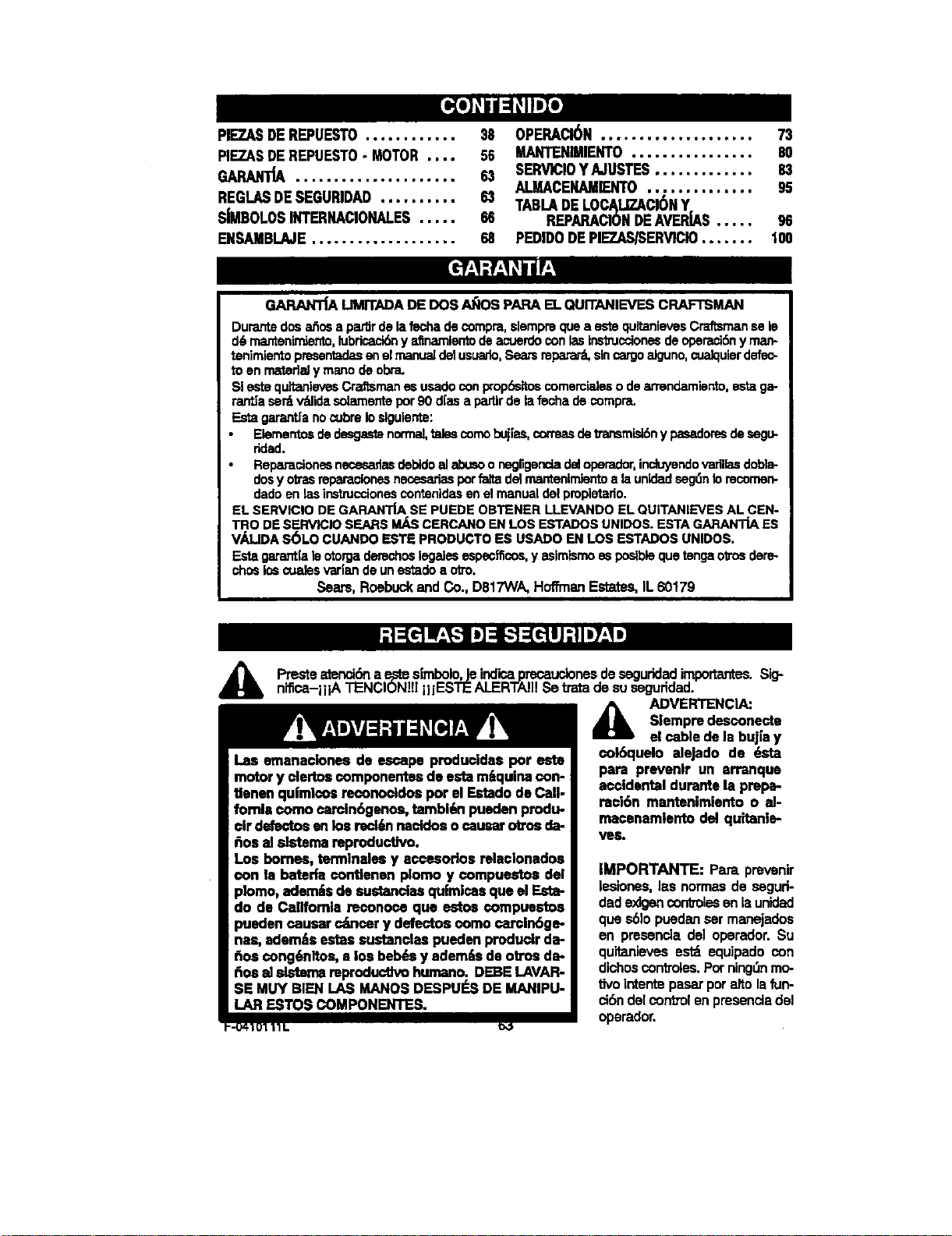
PIEZASDEREPUESTO............
PIEZAS DE REPUESTO - MOTOR ....
• .,. ,o=o,.
REGLASDESEGURIDAD..........
SIMBOLOS INTERNACIONALES .....
ENSAMBLAJE ..................,
38 OPERACI_N .................... 73
S0 MANTENIMIENTO................ 80
6,1 SERV1CIOYAJUSTES............. 83
ALMACENAMIENTO.............. 9S
83 TABLADELOCALIZACI6NY
66 REPARACIC_NDEAVERJAS..... 96
68 PEDIDODEPIEZAS/SERVICIO....... 100
GARAN'_ LIMrTADA DE DOS AI;IOS PAPA EL QUITANIEVES CRAFTSMAN
Durante dosa_os a peu'drde lafschade compra,slempreque a estequitanievesCraftsmanse le
d6 mantenimierrto,lubricaci_ y afinamlentodeacuerdocon lastnstmcciones de operaci6nyman*
tenimlentopresentadasen elmanuaJ(Jetusuado,Searsrepatar_sincargoalguno,cualquierdefec-
to en mateflaly mano de obj.
SI este quitanievesCraftsmanes usadoconprop6sitoscomemialeso dearrendamiento,esta ga-
rantJasert v_lidasolarnentepor90 d[asa partirde lafecha de compra.
Esta garantfanocubreIoslgulente:
Elementosde desgastenormal,tales¢omoLx.'ji'as,con'easdetransmisl6n ypasadoresde segu-
ridad.
Reparacionesnecesariasdebldoalabusoo negUgencladd operador,induyendovaflllasdobia-
dosy otrasreparacionesnecesm'iasporfalta de)mantenimtentoa launidadseg(mb recomen-
dado en las instruccionescontenidasend manualdel propietado.
EL SERVIClO DE GARANTJASE PUEDE OBTENER LLEVANDO EL QUITANIEVES AL CEN-
TRO DE SERVICIO SEARS MASCERCANO EN LOS ESTADOSUNIDOS. ESTA GARANT'JAES
VALIDA S(_LO CUANDO ESTE PRODUCTO ES USADO EN LOS ESTADOS UNIDOS.
Estagarant|ale otorgaderechoslegalesespecificos,y aslmismoes posiblequetenga o'a'osdere-
chosIo_cualesv'arlande unestadoa otto.
Sears, Roebuck and Co., D817WA, Hoffman Estates, IL 60179
,&
Las emanaciones do escape producida$ por este
motory clertoscomponentesdo esta m_qulnacon-
fJenenquimicosreconocldosporel Estadodo Cali-
fornia como carcln6genos,tambl6npuodenprodu-
clr defectosenlos rocl6nnacidosocausarotrosda-
_os alslstema mproductlvo.
Los homes, termlnales y accesodos relacionados
con la baterfa contlenonplomo y compuestos del
plomo,adern_sde sustanclasqulmlcasque el Esta-
do de California reconoce que estos €ompuostos
puedencausar c_ncer y defectosoomo camln6ge-
nas, adem_;sestas sustanclaspueden producirda-
hos cong6nltos, a los beb6sy aden's de otrosda-
_os alsistemareproductlvohumano. DEBELAVAR-
SE MUY BIEN[.AS MANOSDESPUI_.SDE MANIPU-
LAR ESTOSCOMPONENTES.
'-U41UlllL
Preste_enckSna ep-'tesimbolo,Jeindicaprecauclonesdeseguridadimportantes.Sig-
nifica-iliA TENCION][IIIIESTE ALERTA!IISe tratadesuseguddad.
A ._VERTENCI_
Slempredesconecto
el cable dela bujia y
€ol6quelo aloJado de _ta
para prevenlr un arranque
accidentaldurante la prepa-
ra¢|6n mantenimlento o al-
macenamlentodel quitanle-
IMPORTANTE: P_u'aprevenir
lesiones,las normas de segud-
dade)dgencontmlesenla unidad
ques61opuedansermanejados
en presenciadel operador.Su
quitanievesest_ equipadocon
dichoscontroles.Porningt_nmo-
tivointentepasarporaltolafun-
ci6ndelcontrolenpresenciadel
operador,
CAPACITACI6N
1. Leaconatenci6nlesinstrucoionesenel
manueldeoperaci6nyesrviclo. Famlliarf-
case completamentoconloscontroiesy
el useapmpiadodelquitanleves.Apren-
daa detenarelquitanievesy a desen-
ganctmrr_pldamenteloscont_oles.
2. Nuncapermitsa nifiosopermelquita-
nieves.Nuncapermitsqueadultosope-
ren elquitanlevessinlainstrucci6n
apmpiada.
3. Mantangeel_ Iibredepersonas,es-
pecta|mentonifiospequel'losy mascotes.
4. Tengamuchocuidadopezaevitarresba-
Ionesocaldas, especielmantecuando
est6 reb'ocediendo.
PREPARACl6N
1. Inspecoionecomplstamenteel=_=readon-
de seusar_elqultanlevesy retiretodas
lasesteres,trinsos,tablaros,cables,y
otrosobJetosextra_os.
2. Desenganchetodos losembraguesantes
dehacerarrancarelmotor.
3. No opereel quitanievessinvestirpren-
desde inviemoadecuadasparatrabajar
a laintemparie.Vistacalzadoqueled6
buenatracoi6nsobresuperficiesresbelo-
SETS.
4. ManeJeel combustiblecon cuidado;_.ste
es sitamente inflamable.
(a) Useuncontenedoraprobadopara
combustible.
Nunca qu'rlela tape del tanque de
combustible nl ar_adacombu_bie •
un motoren marcha o aun motorca-
liente.
(c)
(co
(e)
Llenaeltanquede combustibleel el-
relibrey contouchecuidedo.Nunca
lienseltanqueen unredntoosrrado.
Vuelvaa colocarlatapedeltanque
decombustibledemanerasegura,y
limpieelcombustiblederramado.
Nuncaalmaosnecombustibleoel
qultanievesconcombusb'sieen el
tanquedentinde unedificiodonde
losvaporespudiesenelcanzarelgu-
nallamaabiertaochispes.
(f) Verifiquequeel qultanievestanga
suficlentecombustibleantesdecada
uso,y dejeunespacioadicionelen el
tanquepuestoqueelcelordelmotor
F-0410111L
y/odelsolhaosqueelcombus'dble
seexpands.
5. Paratodos losquitanievescon motores
dean'anqueel6ctrico,usecablesdeex-
tensi6nconcertificaci6nCSA/UL Use
solamentetomacorrientesquehayans_-
do insteladosdeacuerdocontosregla-
mentesdeinspecci6nlocales.
6. Permitsqueelmotoryel quitanlevesse
aJustenales temperaturesexterioresan-
tes decomenzara despejarlanieve.
7. Siempreusegafasdeseguddadopro-
tectoresparelosojosdurantelaopera-
ci6nomlentresefest_eelgin a_usteo
reperaci6nale unldad,pareprotegarsus
ojosdeobJetose.x_'a,5osquepudiesen
sarlanzadesporel quitanieves.
OPERACI6N
1. Noopereestequitanievesslsst_toman-
domedicinesquepuedancaucarsomno-
lanciaoafestarsuhabilldadpareoperar
elqultanieves.
2. No useelquitanleves slper rnotivos
emociensiesofisicos seIsdi_cultama-
nejarlode formasegura.
3. Nocoloquelesmanos olospiescercao
deba_odepiezessnmovimianto.Man-
t6ngaseentodo momentoa buenadis-
tends delaaberturadeltubede
descarga.
4. Tengamuchocuidadoaloperarelquite-
niecesenoa b'av6sdeentradesdeau-
tos, esnderoso caminosdegrays.
Mant_ngeseelertade peligrosocultoso
trbfico.
5- SigcipeaunobJetoextmSo,pareel mo-
tor,desconecteel cablede labujia,ins-
pecctonemeticulosemeoteelquitanleves
per sihubieraelgin de,-3o,y repdreloan-
tesdearrancarelmotory operarelquita-
nlevesnuevamente.
6. SIel qultanlevescomlenza• w'brarde
maneram0_slva,pareel motory revl'se-
Io inmediatamentopareencontrarlacau-
sa. Generelmente,lavlbrasi6nesuna
advertenctadeelgin problems.
7. Pareel motorcuandodejelapesici6nde
operaci6n,antesdedesobstruirel eloja-
mientodelabarrana/pmpulsoro el tubu
dedescarga,y cuendoef_ cuelquiar
reparaci6n,ajusteo inspecoi6n.
8. Cuandolimple,repareoIospescioneel
quitanleves,eseg6rese dequelabarre-
na!propulsory todeslespedesm6vlles
se encuentrendetenides,y quetodos los
contmles est_ndesenganchados.Desco-
64
nect_elcabledelabujfaymant6ngalo
alejadodela bujlapareevitarunarran-
que accidental.
9. Tometodasiasprecaucionesposibiesal
dejarelquitanievesdesatandido.Desen-
ganchelabarrena/propulsor,pareelmo-
tory retirelaIlave.
10. No hagaanancarelmotoren recintos
uerrados,a_nconlaspuertasy vantanas
abiertas.Losvaporesdeescapesonpeli-
grosos(contianenMONOXIDODECAR-
BONO,unGASINODOROy LETAI.).
11. No useelquitanievesparalimpiar_u'eas
determnoinclinadas(cuestas,pendian-
tes).Tengamuchocuidadocuandocam-
ble dedimccibn.No Intentelimplar
pandiantesmuy pmnunciadas.
12. Nuncaoperaelquitan|evessinquelos
resguardos,placasuoboedispositJvos
de seguddadse encuentrenen sulugar.
13. Nunnaopere elquitanlevescoma dees-
caparatesdevidrio,autom_Mles,vidrie-
ms,s_osdecargaJdescarga,ysimilares,
sinelajusteapropladodel_rmgulodedes-
cargade lanieve.Mantengaa losni6osy
lasmascotasalejadosdel_rea queest_
despejando.
14. No sobmcarguela capacidaddel quita-
nievesel intentarlimpiarla nieve a una
veJocidaddemasiador_ida.
15. Nuncaopereel quitanlevesa altasvelocl-
dadesdet_nsportesobresupel'lP..les
resbalosas.Mirehactaat_s y tangacui-
dadoaJretroceder.
16. Nuncadescarguedirectamentehaniaes-
pectadoresnlpermitaa nadiefTanteal
quitanieves.
17. DesenganchelafueFzamotdzde laba-
rrana/pmpulsorcuandeel qultanieves
sea trasportadoonoest6en use.
18. Utlliue6nicamenteaclltamentosy acueso-
dosapmbadosperelfabricantedel qulta-
nieves(talescornocadenasparalas
rueclas,juegosdearranqueel_'ffico,
etc.).
19. Nucoaopereelqultanievessintenerbue-
navlslbilidadoiluminaci6n.Aseg_rese
siempre que tlena buena estabilidad, y
sujete con f_rmeza el mango. Carnine;
Rul_-,acorra.
20. No trate de alcanzar _treas dificiles. Man-
tenga la establlidad y el balance en todo
momento.
21. No trate de usar el quitanieves para lira-
piartechos.
MANTENIMIENTO Y
ALMACENAMIENTO
1. Revise los pernos con fTanuanCtapara
asegurar que estdn bienapmtados y que
el quitanieves est_ en condiclones segu-
ras de funcionamianto.
2. Guards el quitanieves a una distancla de
fuantes de ignlci6n o de aparatos dorn_s-
ticos que tangan llamas de encandido,
tales come calantadoreS de agua y estu-
;as, secadoras de mpa, etc. Permlta que
el motorse enfTie antes de guarder el
quitanieves en cualquier recinto.
3. Si va a elmacenar el quitanieves per un
periodo prolongado, siempre consulte las
instrucciones del manuel del operador
deride encontrar_i consejos importantes.
4. Mantanga o reemplane las etiquetas de
seguddad • instrucciones, segOnsea ne-
cosario.
5. Mantenga el qultanieves an marcha unos
cuantos minutes despu_.sde despejar la
nleve, para evitar que se congele la ba-
rmna/pmpulsor.
A ADVERTENCIA: Este quitanleves
es pan= use en aceras, enbadas
de auto y otras superficies de te-
rreno planes. Se debe tener culdado al
usar el qultanleves en superficies inclina-
des. NO USE EL QUITANIEVES EN SU-
PERFICIES SOBRE EL NIVEL DEL SUELO
tales come techos de residenclas, de ga-
raJes, porches u otras estmctums o cons-
tTucclones slmllares.
F-O410111L 65
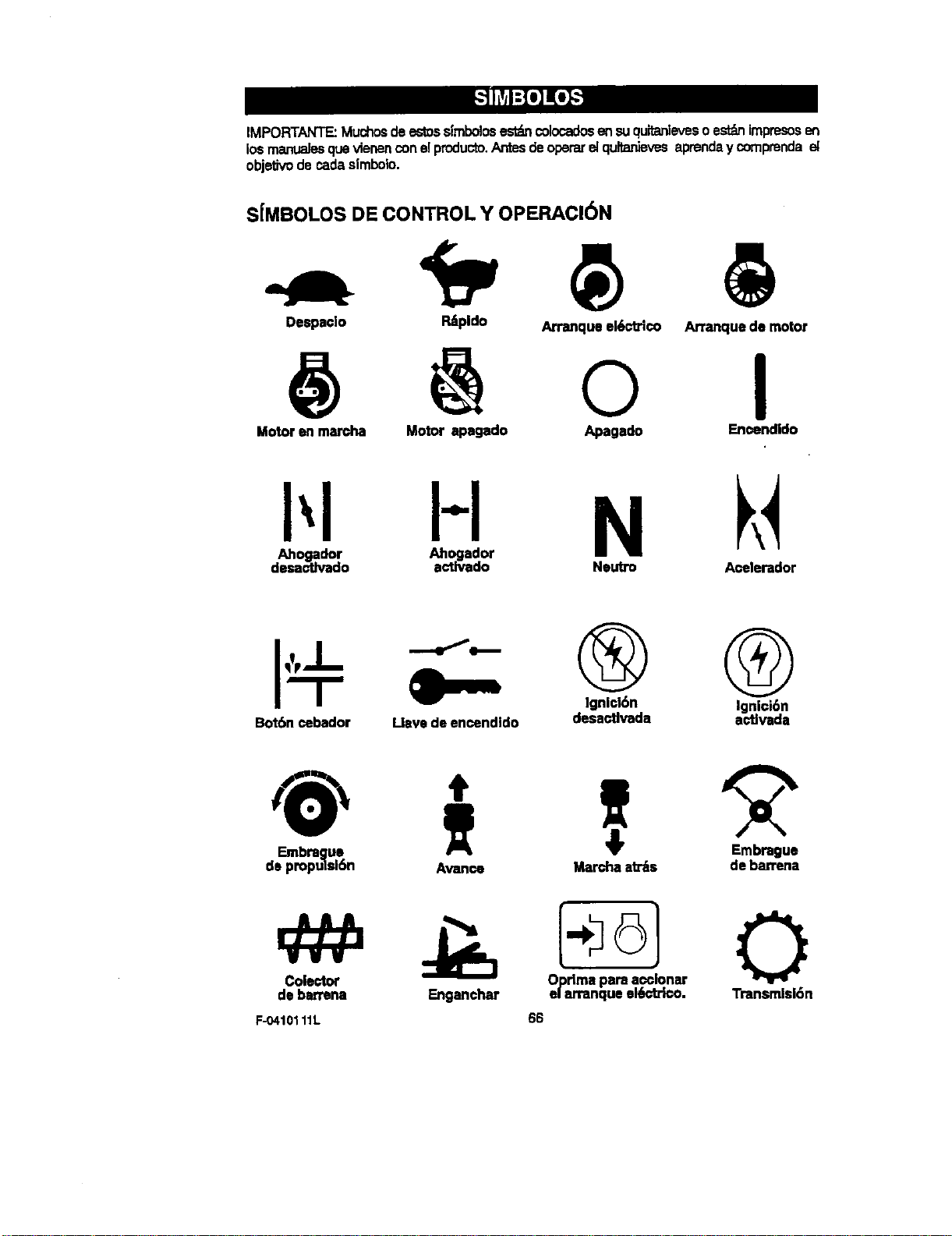
IMPORTANTE:Muchosdeestossimbolosestdncolocadosensuquitanlevesoest_nimpresosen
losmanualesquevienenconelproducto.Antesdeoperarelqultanievesaprenday comprendael
objef_vodecadeelmbo]o.
SJMBOLOS DE CONTROL Y OPERACI6N
Despaelo Patpldo
Arranque el_a'ico
@ @ o
Ananque de motor
Motor en marcha
I
Motor apagado Apagado Enoendido
H N
Ahogador Ahogador
desactlvado actlvado Neutro A_-elerador
Bot6n cebador Llave de encendido
® @
IgnlckSn Ignici6n
desactivada actlvada
Embrague
de propulsl6n
Embrague
Avance Marcha at_s debarrena
Cole_or
debarrena Enganchar
F-O410111L
6] 0
OePdmlarra_qPuaera_cci°n6ctrk_Transmisi6n
66
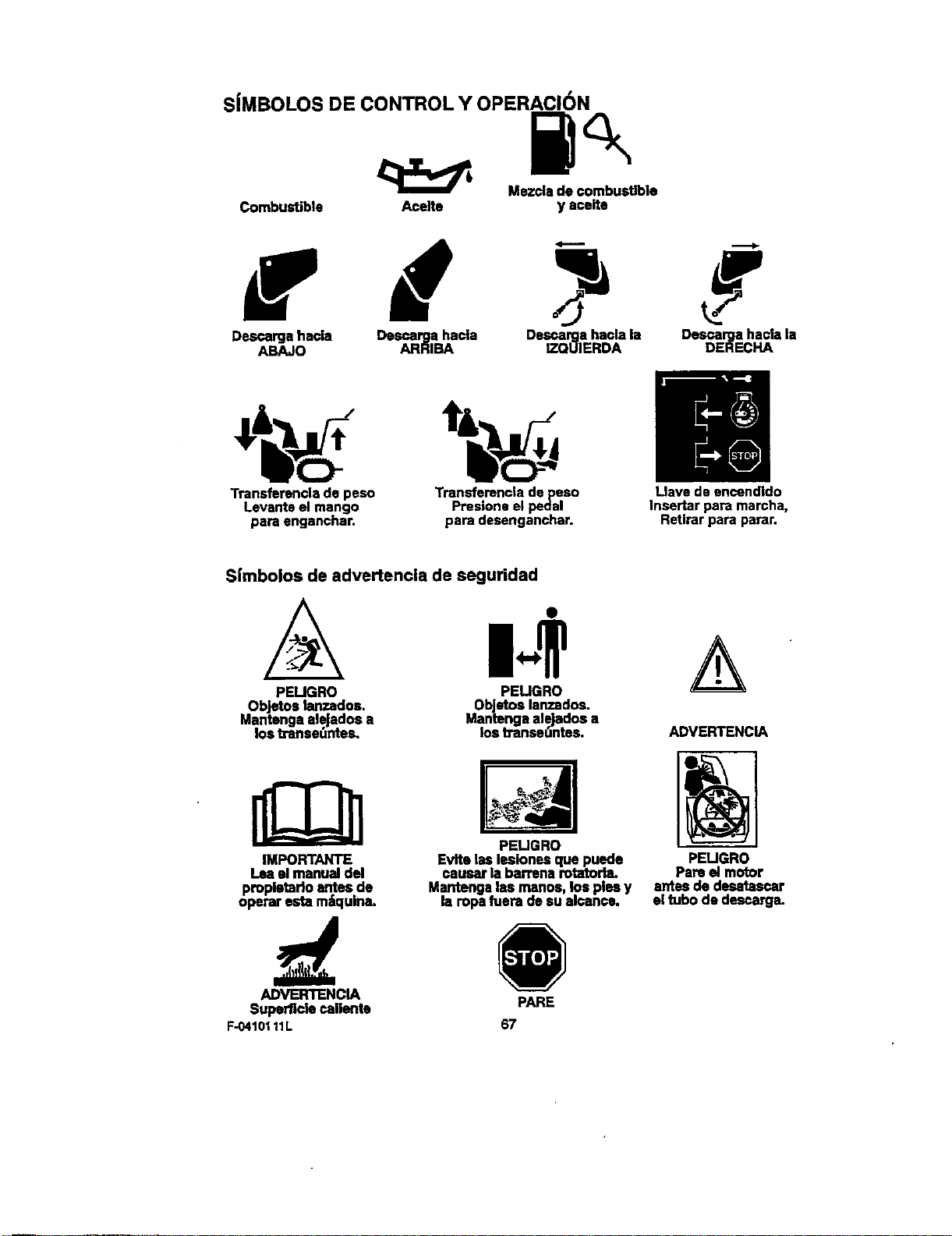
SJMBOLOS DE CONTROL Y OPERACI(_N
Mszclade€ombusUble
Combustible Acelte y aceite
Descargahacla Descargahacla Dsscargahaolala Dsscargahacia la
ABAJO ARRIBA IZQUIERDA DERECHA
Transfsrsncla ds peso
Levante el mango
pare enganchar.
Transferencia ds peso
Presione el pedal
pare desenganchar.
Llave de encendido
Insertar pare marcha,
Retirar para parar.
Simbolos de advertencia de seguridad
PEUGRO PELIGRO
ObJetoslanzados, ObJetoslanzados.
MantengaaleJadosa Mantengealejados a
los tnmseuntes, los tTanse(,ntes.
IMPORTANTE
lea elmanualdel
pmpletario antesde
operaresta m_qulna.
ADVERTENCIA
Superncle callente
F-0410111L
PE_GRO
Evite las lesionesque puede
causer la barrensrotatorla.
Mantengalas manos los pissy
Is ropefuera de sua canes.
67
PARE
ADVERTENCIA
PELIGRO
Pareel motor
antesde desatascar
eltubs dedescarga.
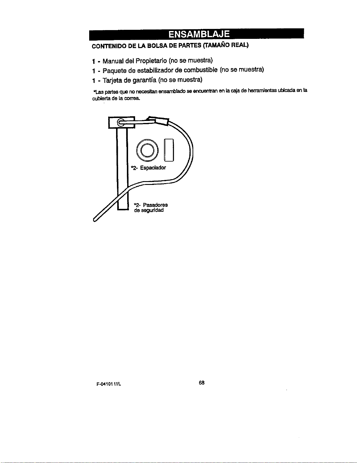
CONTENIDO DE LA BOLSA DE PARTES ('FAMAI;IO REAL)
1 - Manual del Propietado (no se muestra)
1 - Paquete de estabilizador de combustible (no se muestra)
1 - Tarjeta de garantfa (no se muestra)
*Laspartesquenonecesitanensambladoseencuentranenlacajadeherrarnientasubicadaenla
cubiertadelacorrea.
F-O410111L 68
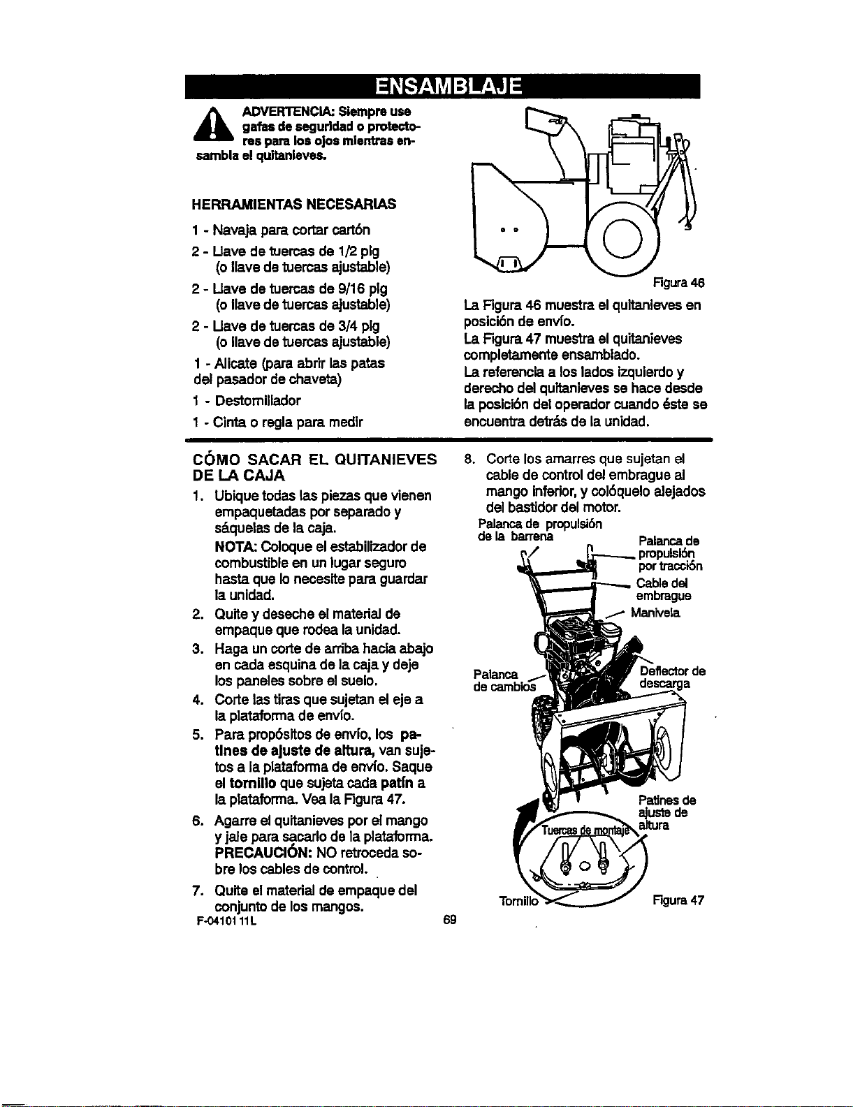
A DVERTENCIA:Slempreuse
galas deseguddado protecto-
res pare los o|osmlentrasen-
sambla el qu_anleves.
HERRAMIENTAS NECESARIAS
1 - Navaja pare cortar cart6n
2 - Llave de tuercas de 1/2 pig
(o Ilave de tuercas ajustable)
2 - I_lave de tuercas de 9/16 pig
(o Ilave de tuercas ajustable)
2 - Uave de tuercas de 3/4 pig
(o ,ave de tuercas ajustable)
1 - Alicate (para abrir las patas
del pasador de chaveta)
1 - Destomillador
1 - Cinta o regla para medlr
Rgura 46
La Figura 46 muestra el quitanieves en
posici6nde env[o.
La FKjura 47 muestra el quitanieves
completamanta ensamblado.
La refemncia a los lados izquierdo y
derecho del quitanieves se hace desde
la posici6n del operador cuando 6ste se
encuentra detr_s de la unidad.
COMO SACAR EL QUITANIEVES
DE LA CAJA
,
Ubique todas las piezas qua vienen
empaquetadas porseparado y
s_quelas de Is caja.
NOTA: Coloque el estabilizador de
combustible en un lugar segum
hasta que Io necesite para guardar
la unidad.
2. Quite y deseche el msteHal de
empaque que rodea la unidsd.
3. Haga un corte de arriba haela abajo
en cada esquina de la caja y deje
los paneles sobre el suelo.
4. Corte lastiras que sujetan el eje a
la plataforma de envfo.
5. Para prop6sitos de envfo, los pa-
tines de aJuste de altura, van suje-
tos a la plataforma de envfo. Saque
el tomlllo qua sujeta cads pat|n a
la ptstaforma. Vea Is F}gum 47.
6. Agarre el quitanieves por el mango
y jele para sacarlo de Is plata,forma.
PRECAUCION._*"*'NOretroceda so-
bre los cables de control.
7. Quite el matedal de empaque del
conjunto de los mangos.
F-0410111L
8. Corte los amarres que sujetan el
cable de control del embrague al
mango inferior,y co]6quelo elejados
del bastidor dal motor.
Palancade propulsibn
dela barrena
Palancade
portra_'_n
Cabledd
embmgue
_Man_ela
Palanca
de
Patinasde
69
Figure 47
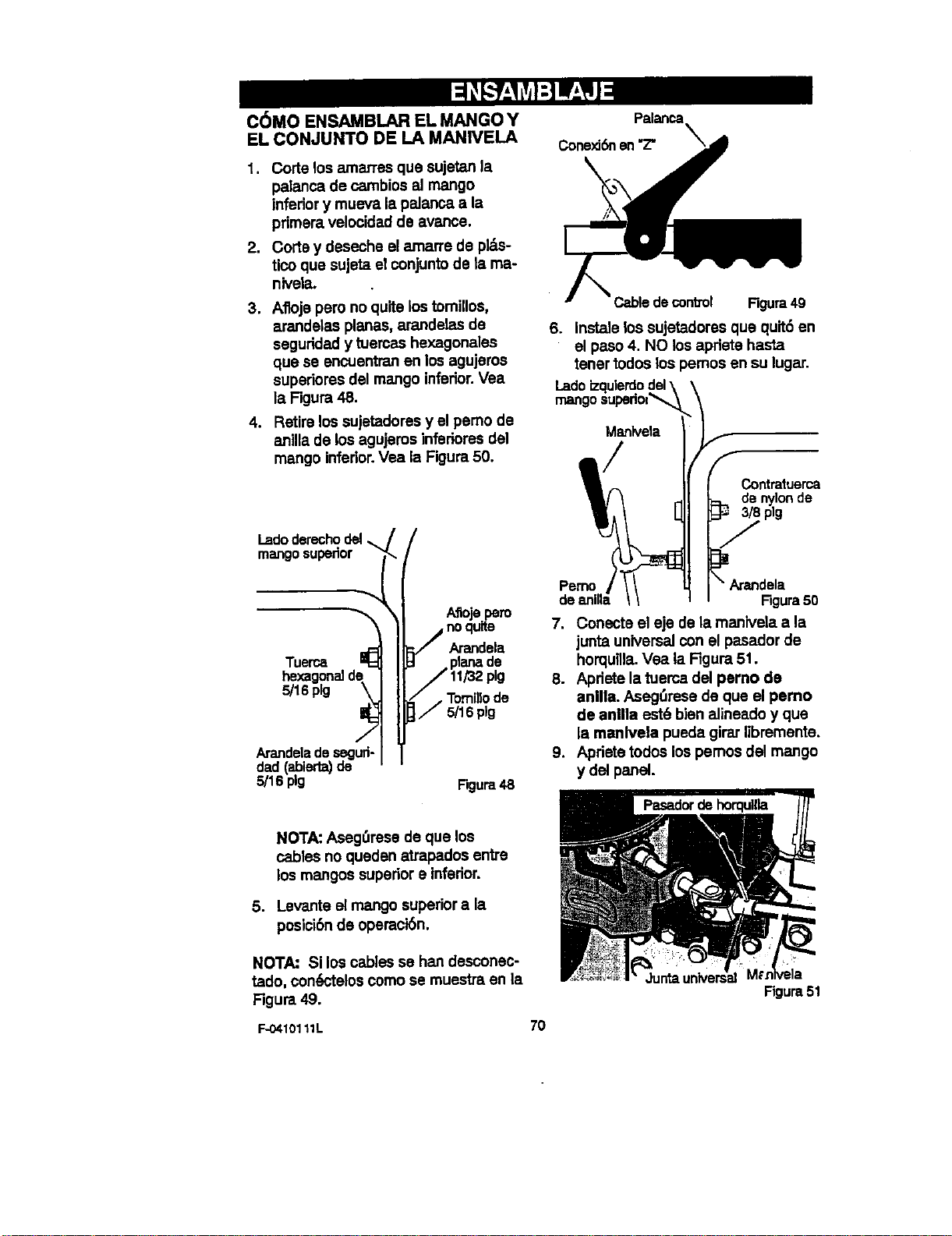
C6MO ENSAMBLAR EL MANGO Y
EL CONJUNTO DE LA MANIVELA
1. Corte los amarres que sujetan la
palanca de cambios al mango
infedor y mueva la pelanca a la
primera velocidad de avance.
2. Corte y deseche el amarre de pl_s-
tico que sujeta el conjunto de ta me-
niveta.
3. Aflojs pero no quite los tomillos,
arandelas planes, arandeles de
seguridad y tuercas hexagonales
que se encuentran en los agujeros
superiores del mango inferior.Vea
la Figura 48.
4. Retire los sujetadores y el pemo de
anilla de los agujeros infedores del
mango inferior.Vee la Figure50.
I.adoderechodel
mangosupedor
Tuerca I_ Amndela
hexagonal de
5/16pig ._ r TomJJlode
5/16 pig
Arandeladesegufl-
dad (abier1_ de
5/16 pig Figura48
ConexJ6nen"Z"
Cable de control Figura 49
6. Instale los sujetadores que quit6 en
el paso 4. NO los apriete hasta
tener todos los pemos an su lugar.
Lado
Pemo
7.
.
.
Manlvela
Contratuerca
:_ de nylon de
plg
\ Arandela
Figura50
Conecte el eje de la manivela e la
junta universal con el pasador de
horquilla,Vea la Rgura 51.
Apriete la tuerca del pemo de
anilla. Aseg_Jresede que el pemo
de anilla est6 bien alineado y que
la manivele pueda girar libremante,
Apriete todos los pemos del mango
y del panel.
NOTA: Aseg,',resede que los
cables no queden atrapados entre
los mangos superior• inferior.
5. Levante el mango superior• la
posici6nde opemoi6n.
NOTA: Si los cables se han desconec-
tado, con6ctelos como se muestra en la
Figura 49.
F-0410111L
70
Figura51
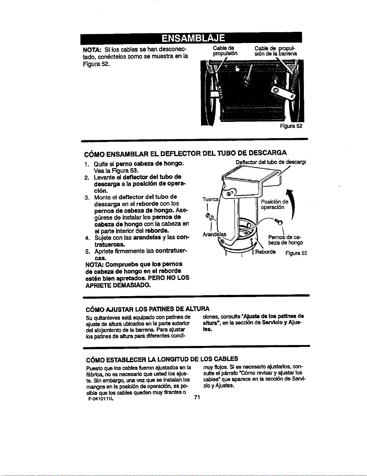
NOTA:SJloscablessehandesconec-
tado,con(_cteloscomo se muestra en la
Figura 52.
Cablede
propulei6n
Cablede propul-
si6ndela barrena
Rgura52
C(_MO ENSAMBLAR EL DEFLECTOR DEL TUBO DE DESCARGA
1. Quite el perno cabeza de hongo.
Vea la Figure 53.
2. Levante eJdeflector del tubo de
descarga a la poslcl6n de opera-
cibn.
3. Monte et deflector del tubo de
descarga en el reborde con los
pernos de cabeza de bongo. Ase-
gOrese de instalar los pernos de
cabeza de bongo con la oabeza en
el parts interior de1reborde.
4. Sujete con las arandelas y las con-
tratuereas.
5. Apdete firmemente las contratuer-
Cae.
NOTA: Cornpruebe que Ioa pernos
de cabeza de hongo en el reborde
est6n bien apretados. PERO NO LOS
APRIETE DEMASlADO,
TUBrCa
Deflectordeltubodedescarg=
Pemo! de ca-
beza de hongo
Reborde Figura53
C6MO AJUSTAR LOS PATINES DE ALTURA
Suquitanievesest_equipadoconp_nes de
ajustedealturaubicadosenla parteextedor
delaloJamientodelabarrena.Paraajustar
lospatJnosdealturaparadiferentescondl-
clones,consulte"AJustede los patinesde
altura",anlasscci6nde Servido y A|us-
tel
C(_MO ESTABLECER LA LONGITUD DE LOS CABLES
PuestoqosloscablesfuemnaJustadosan la
f'_bdca,noesnecesarioque_ losajus-
re. Sinembargo,unavez que se instalanlos
mangosen laposici6n deopemci6n,os po-
siblequeloscablesquedenmuytJranteso
F-0410111L 71
muyflojos,Sies necesarioajustarlos,con-
suiteelpL_,'rafo"C6morevisary Rlustarlos
cables"quaapareoeen le secci6nde _>ervi-
cioy Ajustes.
USTADEREVISI6N
Antesdeusarsunuevoquitanleves,ypara
asegurarqueobtengaai msjorrendimientoy
lamayorsetisfacci6n deesteproductode
calidad,per favorhagaunrepesodetaai-
guiente|istaderevlsi6n:
P" Se han completado todes les instnJccio-
nes de ensemblado.
_," [] canalde descargagiraUbrernente.
v" No quedanpiezassueltesell la cajade
sert6n.
v" Reviselos sujetadores.Compruebequa
todosest_nbienapretados.
Reviselapresi_ deaJredelasnJedes.La
presi6ndeaimcorrectaesde14a 17 PSI.
EnlapartelateraidelesUantesaparesela
presi6ndeaimm_ma parairrl_rlesrue-
des.Nosobrepeseestem_imo.
En los modelos de arranque el_ct]ico, la
unidad ha s|do enviada con el cable dai
aistema de arranque enchufado ai motor.
Antes de utilizarla unidad, sffvase desen-
chufar el cable de arranque del motor.
AI mismotiempoqueapmndea usarsuqui-
tanieves,prestemuchaatenci6na losimpor-
tantesdetailesa continuaci6n:
y,' _ aseitedelmotorest_ai niveladecuado.
Useun aceltedetergentsdealtacelidad
claslficadocomo "Paraservicio SG, SH,
SJ, SLo superior'.
P" Asegt_resequeeltanquedegasolinaest_
Ilenocongesolinalimp'•,fmscay sinplo-
moconunoctanajem|nimode85.
_" Familiar|cesecontodosloscon'o'oles,su
ubicaci6ny funci6n.Opereloscor_oles
antesdehacerarrancarel motor.
F..O4t0111L 72
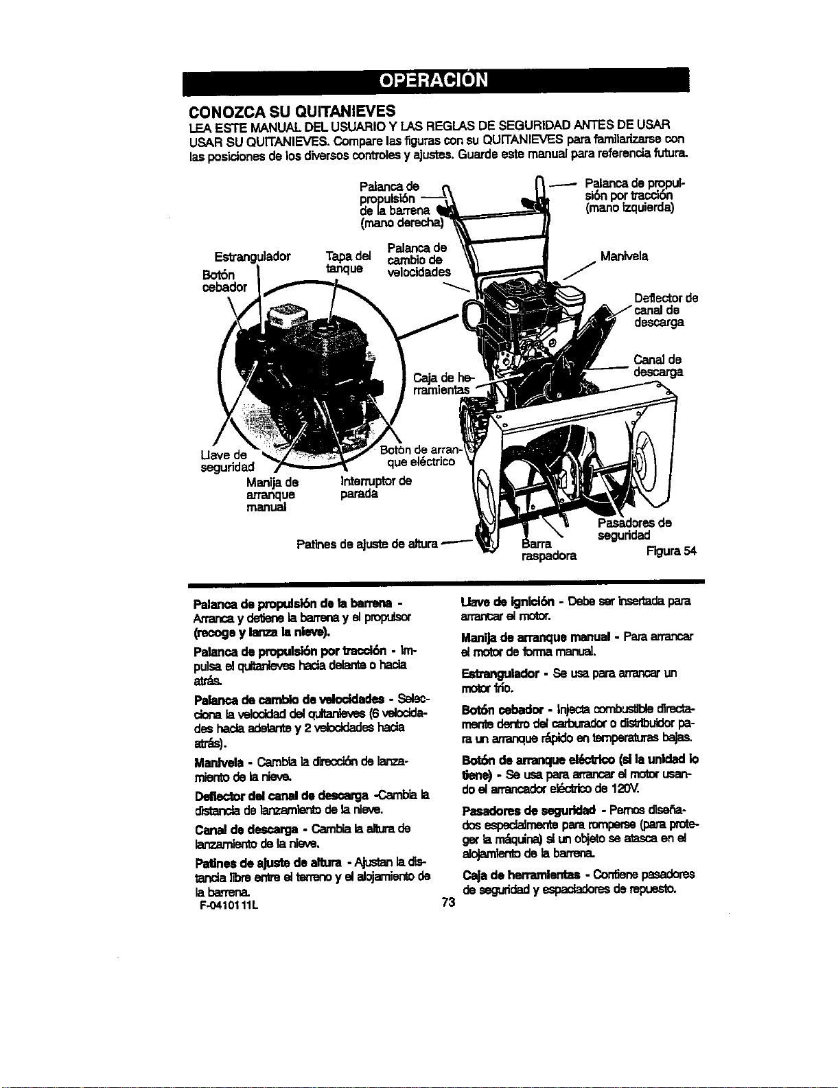
CONOZCA SU QUITANIEVES
LEAESTE MANUALDELUSUARIOY LASREGLASDE SEGURIDADANTES DEUSAR
USARSU QUITANIEVES.Comparelasfigurasconsu QUITANIEVESparafarnilarizarsecon
lasposictonesde losdiversoscontrolesy ajustes.Guardeestemanualparareferenciafutura.
Palancade Palancadepropul-
siSnportmcdbn
(manotzquierda)
cebador
Manivela
Deflector de
descarga
Uave de
seguddad
Manijade
BotOnde
queel_ctrico
Interruptorde
parada
PatinesdeaJustedealtura--'--
raspadora
Pasadoresde
seguddad
F_ura 54
Palancadepn:q:xdsk_deksbarrena-
An.ancay delienelabarrenayet _
(recogoy lanzala nleve).
Palancade propulsk_npot b'acckSn- Irm
pu!sad c_ hada delanteoi'_
Palarmadecamblodewloddades - Selec-
Laveloddaddelqultank_es(6 vdoctda-
deshaciaade_de y 2 veloddadeshacta
av_s).
Mardv_a - Cambialadwecci_delanza-
mientodeianiev_
Dsflectordidcanaldedescarga-Caxnbiala
or=stanchde lanzamientodelanleve.
Canalde descarga- Cambialaaltumde
ianzamientodela nleve.
Pagnesde aJustede altum - Ajustanladts-
tanda libreerie etterrenoy elalojamientode
laban'ena.
F-O410111L
73
Llmmde ignlct6n- Debeseti_sedadapara
an'ancarelmotor.
Manijadearranquemanual- Palmarrancar
elmotordeformamanuad.
Estrangubdor. Se usaparaarrancarun
motor_o.
BofSnoebador- Injectacombusb'bledirecta-
mentederdmdelcarb_'adoro_ pa-
raunananquer"dpldoentemper'_urasbaJas.
Bot6ndean'a_queel6cb_o (sib unldadIo
Uene). Se usaparea_ancarelmotorusan-
doelan'ancadorel_ de120V,
Pasadoresde seguridad- Pemos_-
dosespedalmerd_parerompeme(paraprate-
getlamE_zquina)slunobjetosea_zscaenel
alojamlentode labarrena.
Cajadeherramlentas- Contienepasadoms
deseguridady espacladoresderepuesto.
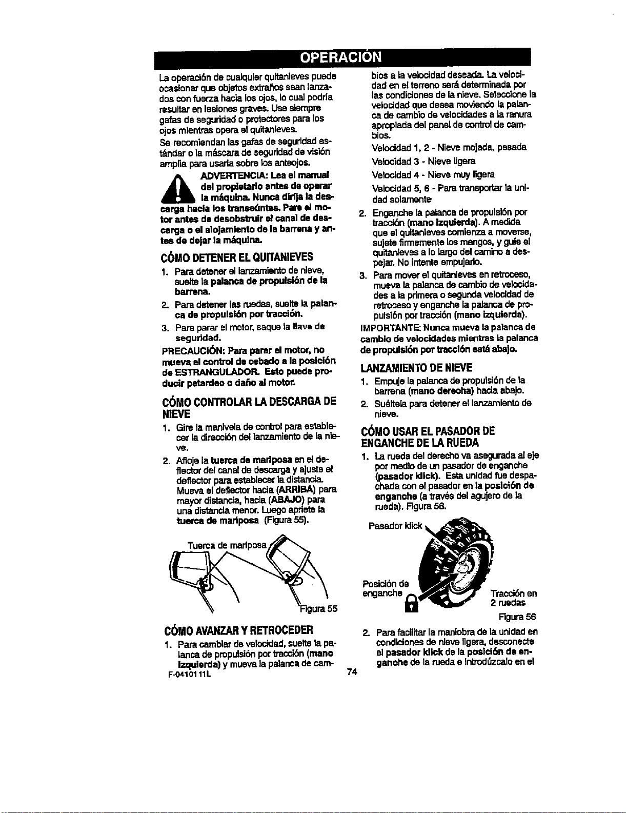
Laoperaci6ndecuelqulerqultanlevespuede
ocasionarqueobJetosextrahosseanlar=e*
dosconfuer'zahacialosojos,lo cuelpodria
resultaren lesionsegraves.Useslompre
galasdeseguddadoprotsctoresparalos
ojosmlontrasoperaelquitanieves.
Se recomiendanlasgalasdeseguddades-
t_dar ola miLscaradesegurideddevisi6n
ampliaparausadasobmlosanteojos.
A ADVERTENCIA:Leaelmanual
didpmpletarlo antesdeoperar
lamlquina. Nuncadldja lades-
carga haclalos transe_nteL Pareel mo-
tor antesde desobstruirel canaldede_-
carga o elalojarnientode labarmnay alp
b_sdo de_u'la m_qulns.
C6MO DETENER ELQUlTANIEVES
1. Paradetenerel I_iento denieve,
sualtelapalancadepmpulelbnde la
barrena.
2. Paradetenerlasruadas,sueltelapalarv
ca de propulsi6nper traccl6n.
3. Parapara;elmotor,saquelaIlave de
seguridad.
PRECAUCI6N: Parapararel motor,no
muevael controlde €l_badoa laposlci6n
de ESTRANGULADOR. Estopuedepro-
ducir petardeoo dafioel motor.
C6M0 CONTROLAR LA DESCARGADE
NIEVE
1. GimlamaniveladeconVolparaestable*
carlaclimc_i6ndellanzamientode lanie*
V_.
2. Aflojelatuema do marlposa enelde*
flectordelcanalde descargay ajusteel
deflectorpan=e_ tadfstanclo.
Muevael deflectorhacia(ARRIBA)para
mayordistancia,hacia(ABAJO)para
unadistanciamanor.Luegoapdetela
tuerca de madposa (Figura55).
Tuerca de
C6M0 AVANZARY RETROCEDER
1. Paracamblardevelocidad,sueltetapa-
lancade pmpulsi6nportracci6n(mane
Izqulerda)y muevalapalancadecam-
F-0410111L
74
biosa la velocldaddeseada.Lavelod-
dadanelten'eriese_ determinadaper
la.scondicionesde la nleve.Selecclonela
velocidadquadescamoviendolapalan-
cade cambiodevelocidadesa laranura
apmpiadade[paneldecontroldecam-
bios.
Velocidad1,2 - NievemoJade,pesada
Velocidad 3 - Nieveligem
Velooidad4 - Nievem_J Iigera
Velocidad5, 6 - Parab'ansportarla unl-
dadsolamente,
2. Enganchela pelancadepmpulsi6nper
traccl6n(mane Izqularda).Amadide
queelquttanlevescomienzaa moveme,
sujetefirmemente losmangos,y guieel
quitanlovsea Iolargoclelcarninoa des-
peJar.Nointenteempujado.
3. Paramoverelquitanlevesenretmceso,
muevala palancadecarnblodevelocida-
desa laprimeraosegundavelocidadde
retrocesoy enganchela paJanoade pm.
pulsi6npertracci6n(maneIzqulerda).
IMPORTANTE:Nuncamuevalapalancade
cambio develocidadesmientraslapalanca
de propulel6nper tracel6nest_abajo.
LANZAMIENTO DE NIEVE
1. EmpujelapWancadepmpulsidnde la
barrena(manedemcha)haciaabajo.
2. Su_ltelaparadetenerellanzamlentode
nieve.
C6MOUSAR EL PASADORDE
ENGANCHE DE LA RUEDA
1. La ruedadel derechovaaseguradael eje
permedlode unpasadorde enganche
(pasadorkllck). Estaurddadft.,ede.spa-
chadaconelpasadorenla poeloi6nde
enganohe(atrav6sdelagujemdela
ruada).Fzjura56.
Pasadorklick_
enganche Tracci_ en
2 ruadas
Rgura56
2. PaLmfacilitarlamanlobradelaunidaden
condicionesde nievetiger&,desconecta
el pasadorIdlckdelaposlcl6ndeen-
ganohede laruedae Intmd0zcaloenel
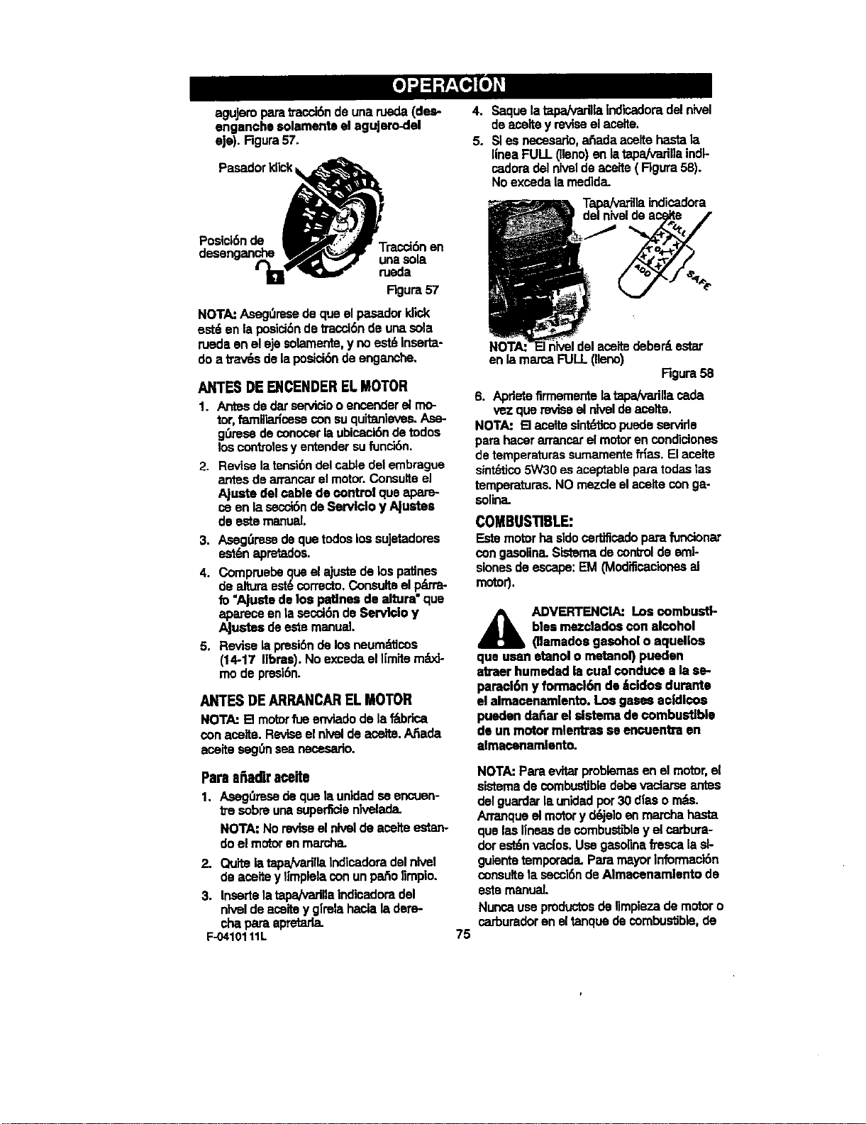
agujeropare_accl_ deunarueda(des-
enganchesolamenteel agujero_lel
eje). Rgura57.
Pasador Idick
Posici6nde
Tracd6n en
unasole
rueda
Rgura5T
NOTAJAseg0resedequeel pasadorIdlok
est-:anlaposici6ndetracci6nde unasole
ruedeenel eje solamante,y no mst_Inserta-
do a tray,s delaposici6nde enganche.
ANTES DE ENCENDEREL MOTOR
I. Antesdedarserv_o o enconderelmo-
tor,famlibu'iceseconsuquitanleves.Ase-
gL_resedeconoosrlaubicaci6ndetodos
los contsotesy entendersufunckSn.
2. Revisela tensi6ndelcabledel embrague
antesdearrencarelmotor.Consulteel
Ajuste delcablede controlqueapare-
os an lasecci6ndeServido y Ajustes
detastemanu_d.
3. Aseg_resedequetodoslos eujetadorms
est6napretados.
4. Compruebequeel ajustede lospatJnes
dealturaest6correcto.Consultselp_'a-
fo"Ajustede los patlneedealtum" que
apareceen la secci6ndeServ_o y
Ajustes detastemanual.
5. Revisela presi6ndelosneum_.ticos
(14-17 Ilbme).NoexcedaelI[mitem_x_-
mode presl6n.
ANTES DEARRANCAR EL MOTOR
NOTA=[] motorrueenvladode laf_brica
con acelte.Reviseelnlvelde aceite.ASada
aceltemsg_nseaneossario.
Pare afiadir aceite
1. Asegt_rseede quela unidedseenmJen-
ITSanbreunasuper_denlvelade.
NOTA:Noreviseelnk,el de aositeestan-
doel motoran marcha.
2. Quitela tapa/%,adllaIndicadoradelnlvel
de=,seitey Iimplelaconunpaholimpio.
3. Insertslatapa/vadllaIndicadoradel
ntveldeaceltey girelahaclaladare-
ch=pareapretarla.
F-0410111L
4. Saquelatapa/VadllaIndlcadoradeJrf_vel
deac_ltey reviseel aoslte.
5. SIas necmsado,afiadaaosltehastela,
llnea FULL(llano)an Is tapa/Variliaindl-
cadorade]nlveldeaoslte(F'_uta 58).
Noexosdela medida.
T_os/vadllaindicadora
niveldeace_te /
75
enla mama FULL(lleno)
Rgura58
6. Apdete firmemente la tapa/vadlla carla
vez que revise et nivelde mselte.
NOTA: [] acelte sint_tJcopusde servide
para hacer arranosr el motor an condiclones
de temperaturas sumamente fries. El acelte
sint_tico 5W30 es aceptable para todas las
temperaturas. NO mezde el acelte con ga-
soline.
COMBUSTIBLE:
Estemotorhasidecertiflosdoparefunclonar
congmsolineLSIstemadecor,b'oldeemi-
sionesdeescape:EM (Modificacianesal
motor).
A DVERTENCIA: Los combusti-
bles mezcladoscon alcohol
(llamadoegasoholo aquelloe
qua usan etanolo metanor)pueden
atraer humedadlacual conduceala se-
pamcl6n y formacl6nde 4cldos durante
elaimacenamlento,Losgasesacldlco$
puedenda_ar el sistemade Qombustlble
de un motormlentrasse encuentraan
elmacenemlento.
NOTA:Pareevitarproblemasenel motor,el
sistemadecombustibledebevactarseantes
delguarderI=,un'dadpor30 dimsom_s.
Arranqueelmotory d6jeloen marc.hahmsta
queIresI|neasdecOmbustibley elcarbura-
dorest6nvacios.UsegasolinefTescaI=,sl-
guientetemporada.Paramayorinformacl6n
consultela secci6ndeAlmaosnamlentode
estemanual.
Nuncauseproductosdelimpiezade motoro
carburadoreneltanquedecombustible,de
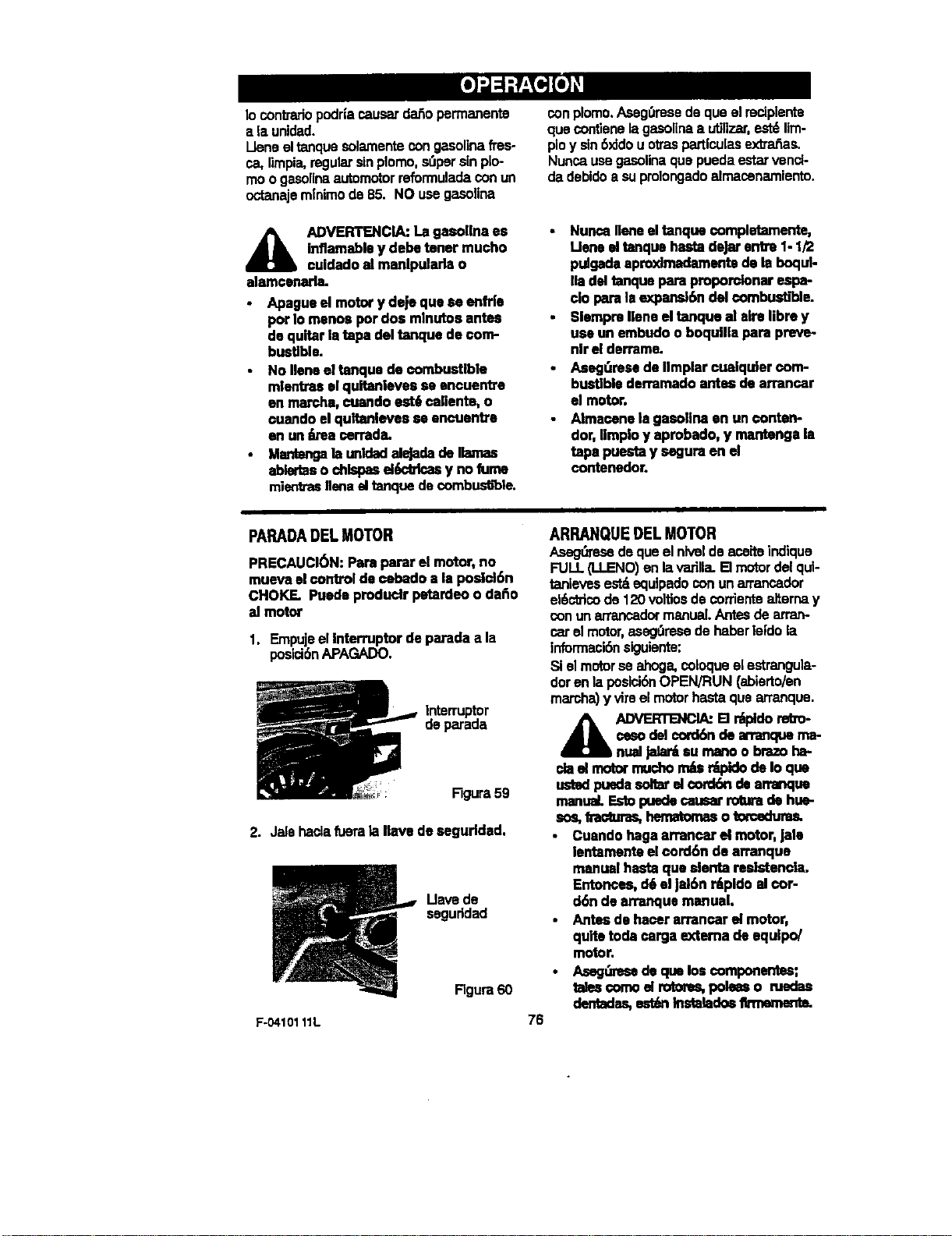
Iocontrarlopodrlacausardar_opermanents
alaunidad.
Lleneeltanquesolamentecongasonnafres-
ca,limpia,regularsinplomo,s_p_rsinplo-
moogasolinaautomotorreformuladaconun
octanajem|nimode85.NOusegasolina
A DVERTENCIA:Lagasollnaes
inflamaMeydebetonermucho
cuidadoalmanlpuladao
alamconarla.
Apaguoelmotoryde|equesoenfrie
porIomonospordosmlnutosantes
dequitarIntapadeltanquede€om-
bustlble.
• NoIlenoeltanquodecombustible
mlentraselqultanlevessooncuenb'e
enmarcha,¢uando est6callente, o
¢uandoel qultanlevesse encuenb'e
on untb-eaterraria.
• Mantengala unldadalejadadellamas
abledaso chlspasel(mbk:asy nofurne
mienlrasIlenaeltanquedecombusb'ble.
con plomo. Aseg0mse de que el r_iplente
que conflene lagasolina a utilizar,est6 Iim-
plo y sin6xJdou otms particulas extraflas.
Nunca use gasolina que pueda estar venci-
da debido a su pmlongado almacenamiento.
NuncaIleneeltanque€ompletamente,
Ueno eltanquehastadew entre1-1/2
p,agadaapro)dmadamsntedo laboqul-
lladel tanqueparaproporclonarespa-
do parala ex1_n_6n del €ombustible.
Slompmnene eltanquo al aimllbm y
useun embudooboqulllapara preve-
nlrel dermme.
Aseg_resede llmplarcualquler€om-
bustlblederramadoantes dearrancar
el motor.
Almacenela gasollnaon un €onten-
dot,Ilmploy aprobado,y mantengala
tapapuestay seguraenel
contenedor.
PARADADEL MOTOR
PRECAUCI6N: Parapararel motor,no
muevaelcontrolde ¢ebadoa la posid6n
CHOKF- Puedepmduclr petardeoo daf=o
al motor
1. Empujeelinterruptor deparadaa la
posici6nAPAGADO.
Ir_terruptor
deparada
Figura59
2. Jalehaclafueralagavede segurldad.
Uave de
seguddad
F-0410111L
Rgura60
76
ARRANQUE DEL MOTOR
Aseg,._resedequeel nlveldeaceiteindique
FULL(LLENO)enlavadlla.B motordelqul-
tanievesest_equlpadoconun arrancador
ei6ctricode120voltiosdecorrientealternay
conunarrancadormanual.Antesdearran-
carelmotor,aseg_resedehaberleidola
informacl6nsiguiente:
SIel motorse ahoga,coloqueelestrangula-
doren laposici6nOPEN/RUN(ablerto/en
march_y vimelmotorhastaquearranque.
A DVERTENCL_B r_do reeo-
ceoodelcord6ndean'anquema-
nuallala_ surnanoo brazoha-
ciaelmotormuchom_ r_lo deIo que
ustedpuedasonarel cord6ndearrar_Je
manual EstopuedecausarrobJmde hue-
sos,fnzctzm:,,hematornaso torceduras.
Cuandohaga arrancarel motor,jalo
lentamenteelcord6n de arranque
manualhastaque slenta reslstencla.
Entormes,d6elJal6nr_pldo al€or-
d6n de arranquemanual.
• Antesde hacer arrancarelmotor.
quitetoda cargaexterna deequIpo/
motor,
• Aseg_se deque loscomponent=;;
tal_ €omoel rotoms,poleaso ruedas
dentadas,est6nInstaladosl_mmente.
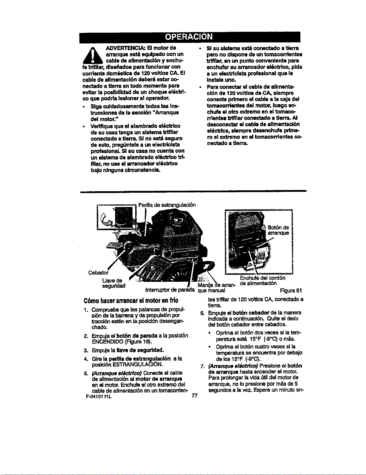
A DVERTENCIA:Elmotorde
arranqueeat4equlpadoconun
cabledeellmentacl6n y enchu-
fe trlfller,dlsefiadospara funelonarcon
corrlente dom6stlcade 120voffiosCA.El
cable deellmentacl6n deber_estar co-
nectado• tlerraen todo momentopara
evitar la poalbllldadde un choqueel_-_b'l-
co qua podrleleelonarel operarlor.
alga cuMadosamente todaslea ins-
tTuccionesde lasecoi6n"An'anque
del motor._
Vedflque qua elelambrado el_--'tdco
de$u casa rangeun eistemetrifller
conectado a tlerra. SI no est_ seguro
de esto, preg_,ntele• un electrielsta
profesionel.SIsu cosa no cuenta con
un sletemade alambradoelOcblco td-
film',no useel arrancadore|(m'_rlco
ba|o nlngunaclrcunstancla.
SI su elsteme est_ conectado a tierra
pero no dlspone de un tomacorrlentes
trlfl|ar, en un punto conyen|ente pare
enchufar su arrancador el0ctrico, plda
a un electdclsta profeslonel qua le
Instale uno.
Para conectar el cable de alimenta-
ci6n de 120 voltlco de CA, slempre
conecte prlmero el cable a la caJa del
tomecordentes del motor, luego an-
chufe el otto exkremo en el tomaco-
rrlentes btfllar conectado a tlerm. AI
desconectar el cable de elimentacl6n
el_rica, slempm desenchufe prime-
ro el extmmo en el tomecorrientes €o-
nectado • tlerra.
Perilladeestrangulaci6n
Cebador
Llave de
seguddad
C6mohacerarrancarelmotorenfri0
1. Compruebequalaspelancasde propul-
si6ndelabarrenay depropuisi6npot
t_'acci6nestt_ en laposid6ndesengan-
chedo.
2. Empujeelbot6n de parade• leposici6n
ENCENDIDO(Figure16).
3. Empujele#ave deseguridad.
4. Girelepedlle de estrangu,leci6nale
posici6nESTRANGULACION.
5. (Arranqueel6ctrico) Conecteel cable
dealimentaci6nel motorde erranque
enel motor.Enchufeelottoex_emodel
cablede alimentaclSnenuntomecorrien-
F-0410111L
Enchufedelcord6n
Manlt,_e arran- dealimentad6n
quamanual Rgura61
tea _fllar de 120 vol_iosCA, coned, ado •
tierra.
6. Empuje el bot6n cebedor de la manera
indicada a contJnuact6n. Quite el dedo
del bot6n cebador entre cebados.
• Opdmaelbot6ndosvecossllatem-
peraturaest_ 150F (-9°C)o m_.
Opdmael bot6ncuatrovecossila
temperatureseencuentmpordebajo
deIce15°F (-g°C).
7. (Arranqueel6ctrlco) Presioneelbot6n
de arranquehastaencenderel motor.
Paraprolongarlavlda(=tJldel motorde
an'a_ue, noIopresioneporreELsde5
segundos• lavez. Espemunmlnutoan-
77
trearranquesparapermltirqueelmotor
dearranqueseenfT[e.
8. (Arranquea manual)JaJelentamente
la manlJa de arranque manual has-
ta qua sienta resistancia y entonces
j_lela r_pidamonte pare arrancar el
motor. Nosusltelamanilainmsdiata-
mantodsepu_sdeJaJada.DeJequela
maHJadelananquemanuaJse enrolls
lentamerrte.
9. Sielmotornoarrancaa los5 6 6 Inten-
toe,lealas!ns_ucelonessobm:Dificu;tad
paraarrancarenla "Tablade/oca/izad_
y reparani6ndeaverias'.
10.Permitsqueelmotorse calienteporve-
dosminotos.Miant_'aselmotorsecalian-
ta,aJustelapedlla de e_rangulac_n
movi_ndolahactala posici6nENMAR-
CHA.Espemhastequaelmotor est6an
marcha suave antesdecadsajustedel
esbangulador.
11.(Ar_nque el6ctrlco) Desconecteel ca-
hiedealimentack_n,primemdeltomaco-
rr|entesyluegodel motordesrranque.
C6mo hacer arrancar un motor caliente
sI est_axrancandounmotorcaliantedes-
pu_sdehabedoapagadopotunperiodo
corto,deJelapa_,w.ade/estrangutadoran la
posici6n=DESACTIVADO"y noopdmael
botbncabador.SIel motornoananca,alga
lasinstrucelonessobreArranquedelmotor
an frio.
ARRANQUECONGELADO
Slel motor dearranque_ ¢ongeladoy no
enclandeel motor,algalospsecasiguiantes.
1. Jeletentscuerdadelmotordearranque
comoseaposible.
2. Sueltelaman[jadearranquemanualy
d_ela enrollarseconfuerzaconb'aelmo-
tordearranque.RepitahastequaIogm
encenderelmotor.
Cuandohacaffio,unmotorcalianteprodud-
condansaci6n.Pare ayudera evitarqua
se congelanel arranquemanualy loscon-
trotesdel motor,procedadela mBnerasi-
gulantedsepu_sdecadstrabajode
remocl6ndenieve.
1. DeJequa el motor (apagado) se enfrl'e
uno$ cuatltos minutos.
2,
31
Jalelantamenteelcord6n(cuerda)de
arranquehastequasiantaresistencia,
luP-_Ode,isdejalaroPermitsquael cord6n
vuelvaa enmllarse,Repita_ vecas.
Conel motorapagado,limpletodalanie-
vey humedadde lacublertadelcarbura-
dorenlazonede loscontrolesy las
paleness.Asimismo,mueva lapelanca
delestrangulador/ahogadory lamanlja
dearranqusvariesvecse.
A DVERTENCIA:Nuncaarran-
que el motordentro deun re-
ointocerradoo on ,treescon
Pecavenffiacl6n. Los gasesde escape
del motoreontlenan MONOX]DODE
CARBONO,UNGAS INODOROY MOR-
TAL MantengsIss manos, lospies, el
poloy is ropesuelta elejados de laspar-
tes an movimlentotanto del motorcomo
del qultanieves.
I.as partse del motor,partlculannante
el silenclador,se ponen muy celien-
tes. [] contaoto puedeprodtmirque-
madura=;severaadebldo alcalor. Deje
qua el motorse enfrieantes detocar-
Io.
Los ni_osnuncadeben operarel qul-
tanleves.Los adultos no cape,-Itados
nuncadebenoperarel quitanleve&
AsegOresede qua on el&reaa despe-
jar no heyapersonas,especlalmente
ni_osPeque_os y mascotaa.
No deja nunca el qultanievesdesaton.
dido m|enb'as el motorest_ encendl-
do. LOspersonasqua opemn el motor
oequipe deden habarleido dotenida-
montey entendldoias instrucolones
de oparael6n.
F-0410111L 78
C6MO QUITARLANIEVEY ESCOMBROSATASCADOSDELABARRENA
_k ADVERTENCL_:No intentequl-
tar [a nlevenl escombms atas-
cados en la barrenacon sus
manos. Useel I= barrade Iimpiezapara
quitar lanieve o escombros.
EnlaparledeardbadeleloJamientodelaba-
rrenase_ unbast6nder_¢Mza. U_-
liceelbast6ndelirr_ezaparaqu_arlanleve
atascadaenelalojamlentode labarrena.
Sueltelapalancadepropulsi6ndela ba-
rrena.
Retire(singirat)laIlavedeseguridad.
Desconecteelcablede labujla.
No coloquelasmanosen labarrenao
canaldedescargeLUseelbast6ndetim-
piezaparaquitarla nleve.
CONSEJOS SOBRE EL LANZAMIENTO DE NIEVE
1. Para un rendimiento m_L_dmode su quita-
nieves, al despejar lanieve ajuste lave-
Iocidad sobre el termno. Avance
lentamente en nieve profunda_congela-
da, o mojada. SI las ruedas palJnan,re-
duzca la velocidad de avance.
2. El lanzamiento de nieve es mi_seficiente
sl el tmbajo se maliza inmediatamente
despk_.Sde la nevada.
3. Para una remoci6n compieta de la nieve,
traslape ligeramente cada camino adop-
tado previamente. En nieve profunda, su-
perponga los barfidosentre sf para evitar
sobmcasgar la m_uina.
4. La nieve debeHa ser descargada en la
direcci6n del vlento slempm que sea po-
sible.
5. Para uso normal, ajuste lospatines de
altum de manera que la barra raspadom
quede a 1/8 de pulgada sobre lospa_-
nes, Para suparfides de nieve sumamen-
te compacta, ajuste los pafines de altum
haciaarribade maneraquelabarraras-
padora hagacontactoconelsuelo.
6. Ensuperficiesdegravao pledratdtura-
da, ajustelospatlnesde altuma 1-1/4
pulgadaspordebajodeI= barraraspado-
ra. Consulteel_ "AJustede los
patlnes dealtura"en lasecci6ndeSer-
vlclo y Alustesdeestemanual.Este
ajustees Importantepareque lam_.quina
no recojay lancepiedrasni grava.
7. Despu6sde completarel trabajodedes-
pejarlanleve,dejeel motorenmarcha
pot unoscuantosmlnutos,estoderretir_
la nievey hieloacumuladosalrededordel
motor.
8. Umpiecompletamenteelquttanleves
despu6sde cadauso.
9. Quitetodaacumulaci6nde hieloy niew
y todomaterialexttar3odel qultanleves,y
enJuagueconagua(sifuemposlble)para
removertodalasaluotrosquimicos.Se-
queelquitanievesconun par3o.
F-O410111L 79
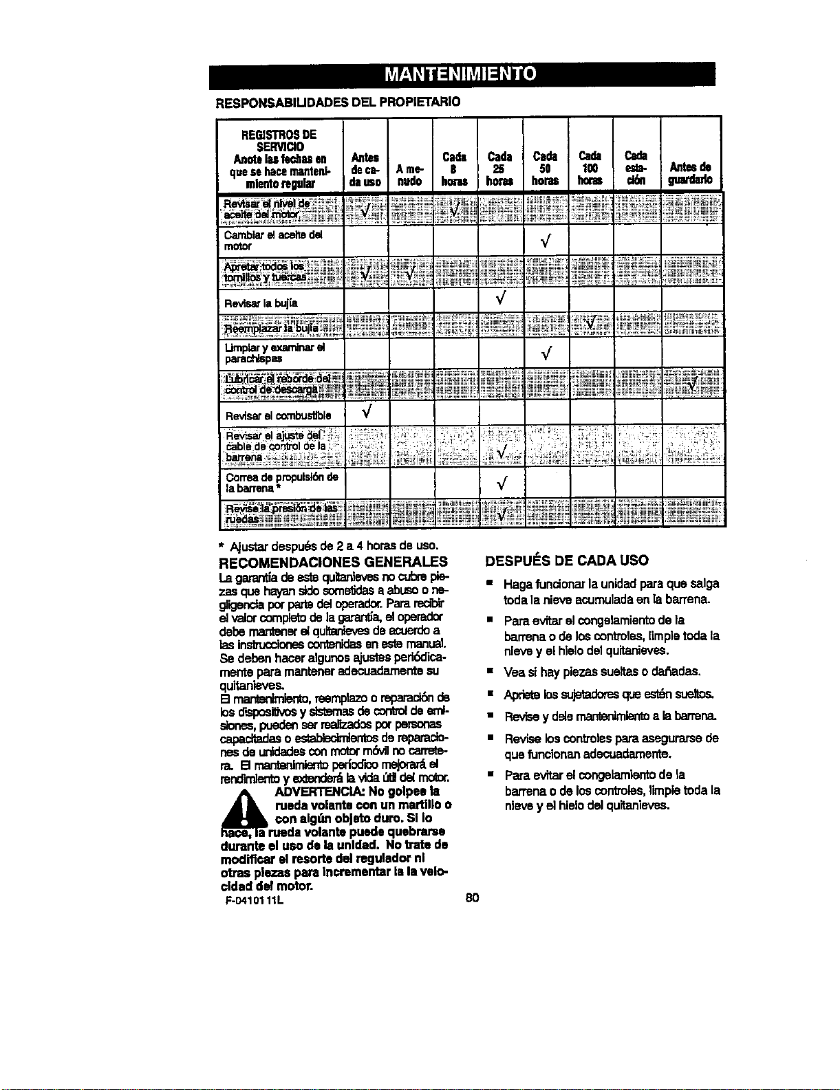
RESPONSABILIDADESDEL PROPIETARIO
REC_STROSDE
SERWCIO
cluesehacemanteni- deca- Ame- 8
mlentotegul_ dauso nudo honus horas horas ck_ gua_lado
Camblare_ace_ del _f
motor
V
_oslos ,ii::E_
RevLs_ la bujla
Umplaryexaminar_
parad',_spas
¢
Revisar el combus_ble "_
Oorma de propuls_6n
la barrena * _/"
* Ajustardespu_sde2 a 4 horasdeuso.
RECOMENDACIONES GENERALES
Lagarantladeestequitanle_snocubmpie-
zasquehayanstdosorne_lasa abusoone-
g_igenctaporpa.,todeloperador.Pararecib_
_ w_r complotode ]a_a, _ _
debo mant_'_r_ q_Itar_ de act,'ordoa
lasinsbuccionescontenidasenestomanual
Se debenhaceralgunosajustesperi6clica-
mentepara manteneradecuadamentesu
quitanieves.
B mar_r,lmler_, reemp_:_oore_ de
losdisposi_vosy slstemasdecontroldeeml-
slones,puedenset_dos potpe_onas
capadtadasoes_ab_ doreparacb-
nesdeuntdadesconrnotorrn_41nocarmte-
ra. B rnantonlmier_p_iocr=orneJorar_el
rend'_nto y _ lavida_1 d_ motx,
_a DVERTENCLAJNo golpee la
medavolantecon un martlllo o
con algunobJatoduro,Sl Io
ruedavolantepuedequebrarse
durante el uso de la unldad. No bate de
modiflcar el resorte del regulador nl
otras p|ezas para Incrementar la Is velo-
cldad del motor.
F-0410111L
DESPUi_S DE CADA USO
• Hagafundonarla unidadparaquesalga
todalanieveacumuladeenlabarrena.
• ParaevitarelcongelamientodeIs
barrenao deloscontmles,limpletodala
nievey el hlelodelquitanieves.
• Vea sihaypiezassueltasodar'_adas.
• Apdetelossujetadomsqueest_nsusltos.
• Revisey delemanter_ientoa labarrena.
• Reviseloscontrolesparaasegurarsede
quefunclonanadecuademente.
• Paraevitarelcongelamientode la
barrenaode loscontroles,limpietodala
nievey elhieIodel quitanleves.
8O
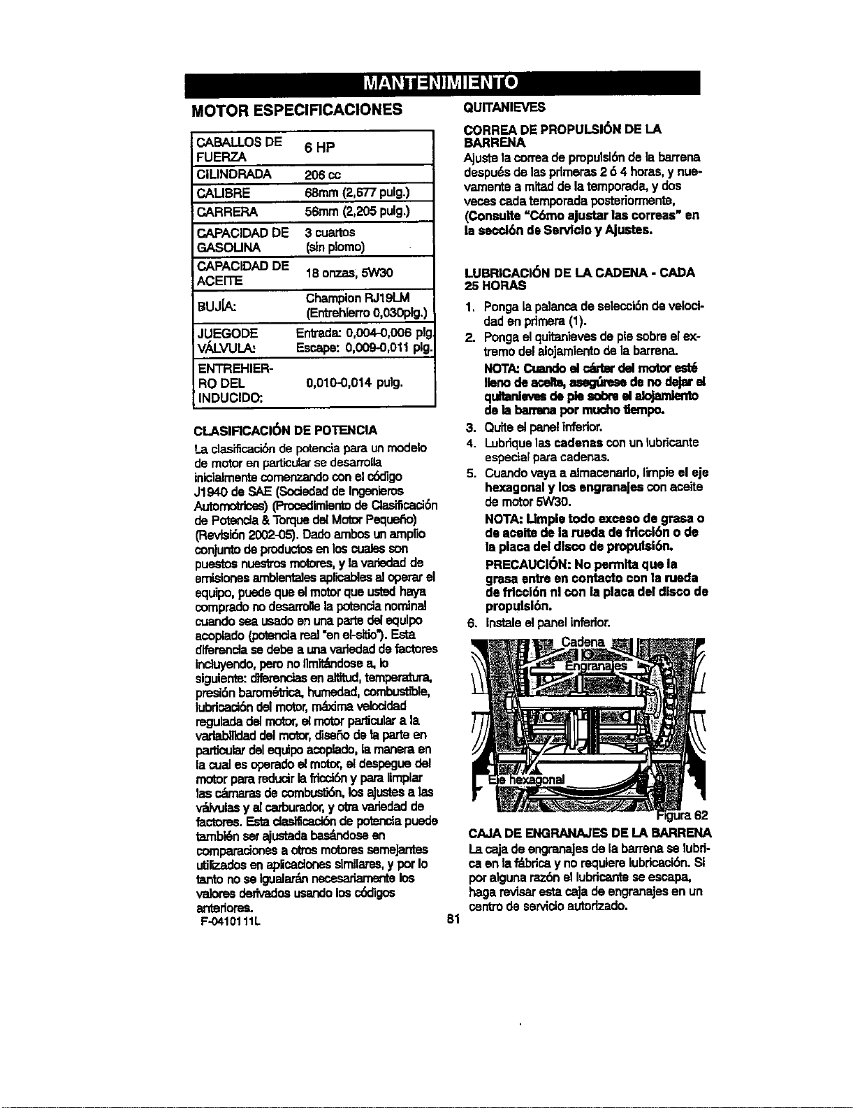
MOTOR ESPEClRCAClONES
CABAl.LOSDE 6 HP
FUEFIZA
CILINDRADA 206 cc
CALIBRE 68ram(2,677pulg.)
CARRERA 56ram(2,205pulg.)
CAPACIDADDE 3 cuastos
GASOUNA (sinplomo)
CAPACIDADDE 18onzas,5%4/30
ACEITE
ChampionRJ19LM
BUJLa': (Entrehierro0,030pig.)
JUEGODE Entrada:0,004-0,006 pig
Vik!._VULA: Escape:0,009-0,011pig
ENTREHIER-
RO DEL 0,010-0,014 pulg.
INDUCIDO:
CLASIRCACI(_N DE POTENCIA
La clasificaci6nde potenciapara un modalo
de motor en particularse desarrolla
iniclalmente comenzando con el cbdigo
J1940 de SAE (Sociedad de Ingenleros
Auto_) (Pmosdimisntode Clasilicaci6n
de Potancla & Torquedel Motor Pequefio)
(Flevtal6n2002-05). Dado ambos tin amplio
conjunto de productosen los cuales son
puestos nuestms motores,y la variedad de
emisiones amblentalesapliosblssal opel'at el
equipo, puede que el motorque ustedhaya
comprado no dosarrollela potancia nominal
cuando sea usado ec una parte del equlpo
acoplado (potanda real =enel-sitio3. Esta
diferencia se debe a uriavarledad de factores
incluyendo,pero no limit_mdose a, io
siguiente:dlferenoiasen altitud,temperatura,
presi6n barome_ica, humedad, combustible,
lubriosck_ldel motor,r'ni_ma veloddad
regulada del motor,el motorpafdculara la
variabT_laddel motor,diser_ode la parte en
particulardel equipo acoplado, la manera sn
la oual es operado el motor, et despegue del
m_or para mducir lafricel6ny para limplar
las _ de combus06n,los aJustesalas
v'ralvulosy alcarburador,y otra varledad de
factoms. Esta ct_n de potenoiapuede
t_'nbldn s_ ajustada bas_ose en
comparacinoos a otrosmoiores semeJantes
utilizadosen apicaclones similams, y pot Io
tanto no se igualartflnnecesadamente los
valores dedvados usandolos r._dlgos
antedoms.
F-0410111L
QUITANIEVES
CORREA DE PROPULSl6N DELA
BARRENA
Ajustela correade propulsl6ndela barrena
despu_.sdelaspdmeras2 6 4 horns,y nue-
vamentea mitadde latemporada,y dos
veoss cadatemporadapostedormente,
(Consulte "C6mo ajustarlas correos"en
la secd6n deServlcloy AJustes.
LUBRICACI6N DE LA CADENA- CADA
25 HOP.AS
1. Pongala pelancade selecci6nde velod-
dadan primera(1).
2. Pongaelquitanfevesdepiesobreelex-
tremodeleloJamientodela barmna.
NOTA:Cuandoel c4rblrdelmotorest6
llenode aosltm,_ denodejarel
qunanlevosde piesobmelalojanden_
dela banma pormu(:hotlampo.
3. Quiteel panelinferior.
4. Lubriquelascadenas conunlubricante
especialparacadenas.
5. Cuandovayaa almacenado,nmpieel eje
hexagonaly los engranaJescon ficeite
demotor5W30.
NOTA:Umpie todo exossode grasao
de aceitedelameda de_cci6n ode
la plaosdel discode propul$16n.
PRECAUCI6N: No perrnltaque la
grasa entreen contactoconla rueda
de frlcci6nnl con la placadel discode
propulsl6n.
6. Instaleelpanelinferior.
Cadena
81
CAJADE ENGRANAJESDE LA BARRENA
La cajade engranaJesdela barrenaselubri-
ca enlaf'_briosy norequiemlubriosci6n.Si
poralgunaraz6nel lubdcantese escapa,
hagarevisarestacajadeengranajesan un
centredeservicioautorizado.
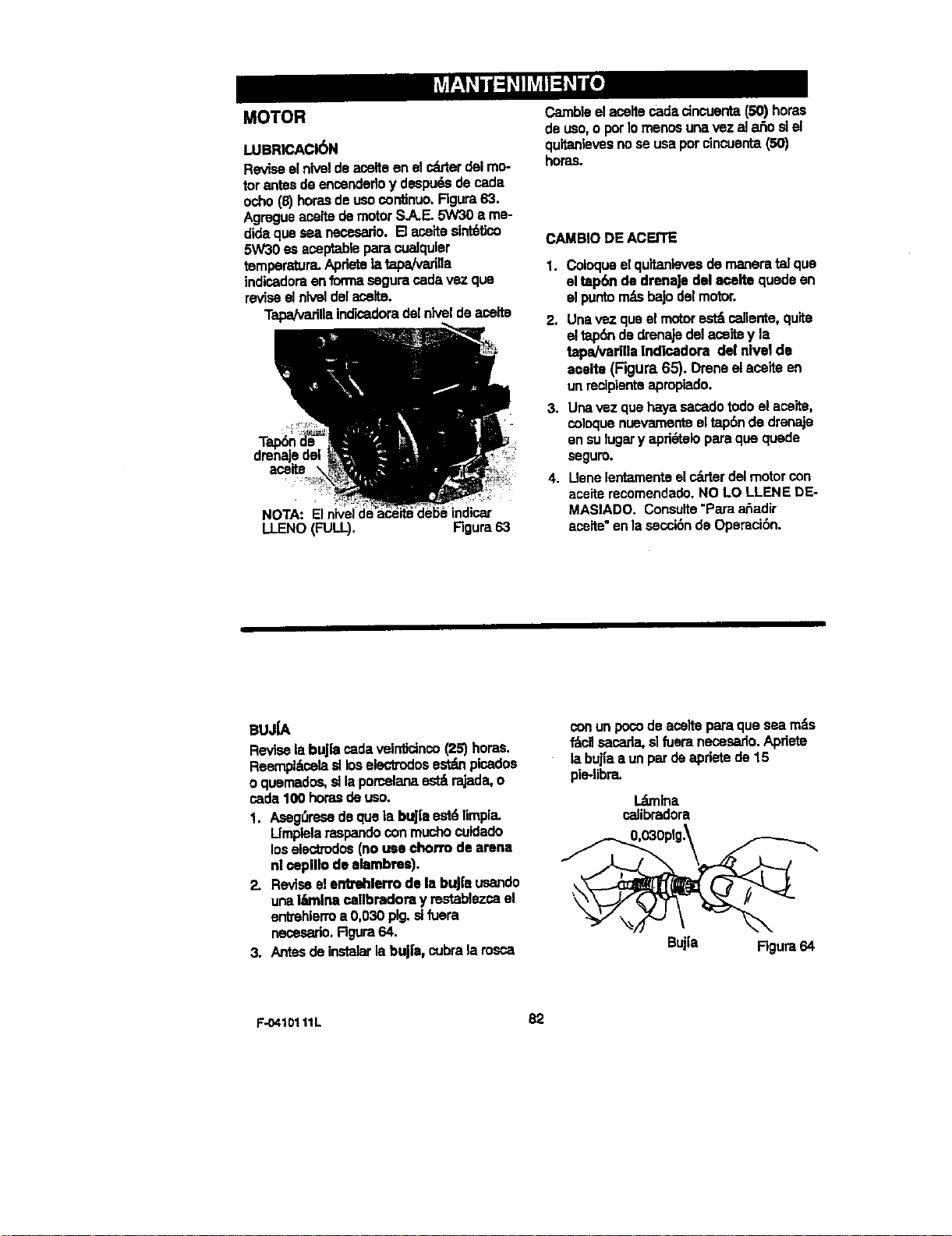
MOTOR
LUBRICACIbN
Reviseelniveldeaselteenelcritterdelmo-
torantesdeensendefloy despu6.sdecada
ocho(8)horasdeucocontJnuo.FIgura63.
Agregueaseitedemotor S.A.E.5W30a me-
didaque seanecesado.[] aceitesint6Uco
5W30es aseptablepara cuelquler
temperatura.Apdetela tapaivarilla
indicadoraenformaseguracadavez que
reviseelntveldelacelte.
TapNvarillaind]sedoradelrdveldeaseite
NOTA: Elnivei _::_:_
LLENO(FULL). Rgura63
Cambleelaseltecadacincuenta(50) horas
de uso,o porIomenosunavezala_osiel
quitanlevesnoseusapotcincuenta(50)
horas.
CAMBIODE ACEITE
1. Coloqueelquitanlevesde maneratalque
el tap6n de drenaJedel aceltequedeen
elpuntom_sbajodelmotor.
2. Unavez quaelmotorest_cafiente,quite
eltap6nde drenajedelaseitey la
tapa/varilla[ndicadom del nivelde
aceite(Figura 65). Dreneelaceiteen
unrecipientsapmpiado.
3. Unavez quehayasecadotodoelase'_,
coloquenuevamenteeltap6nde drenaje
enSuluga_y apri_teloparaquequede
segum.
4. IJenelentamenteelc_rterdelmotorcon
acelterecomendado.NO LOLLENE DE-
MAS/ADO. Consu/te=Paraaliadir
acette"enlasec_6ndeOperaci6n.
BUJiA
ReviselabuJ{acadaveint_cinco(25)horas.
Reerr_l_selaslloselectrodosest_ picados
o quemados,sllaporcelan-est_rajada,o
cads100horasdeuso.
1. Aseg_resedequelabuJ|aest6limpia.
Lfmplelaraspandoconmucho cuidado
loselecbodos(nousee.,horrodearena
n|_pillo de alambms).
2. Reviseelentrehlerrodela buj|e usando
unaIkmlnacallbmdora y restablezseel
en'_ehierma 0,030pig.sifuera
nesesario.Rgura64.
3. Antesdeinstalarlabuj|e, cubrala rosca
con un poco de aselte para que sea m_=s
_cll secada, slfuem necesedo. Apriete
la bujla a un par de apdete de 15
pie-libra.
l._bnlna
calibradora
Buj{a Rgura64
F-0410111L 82
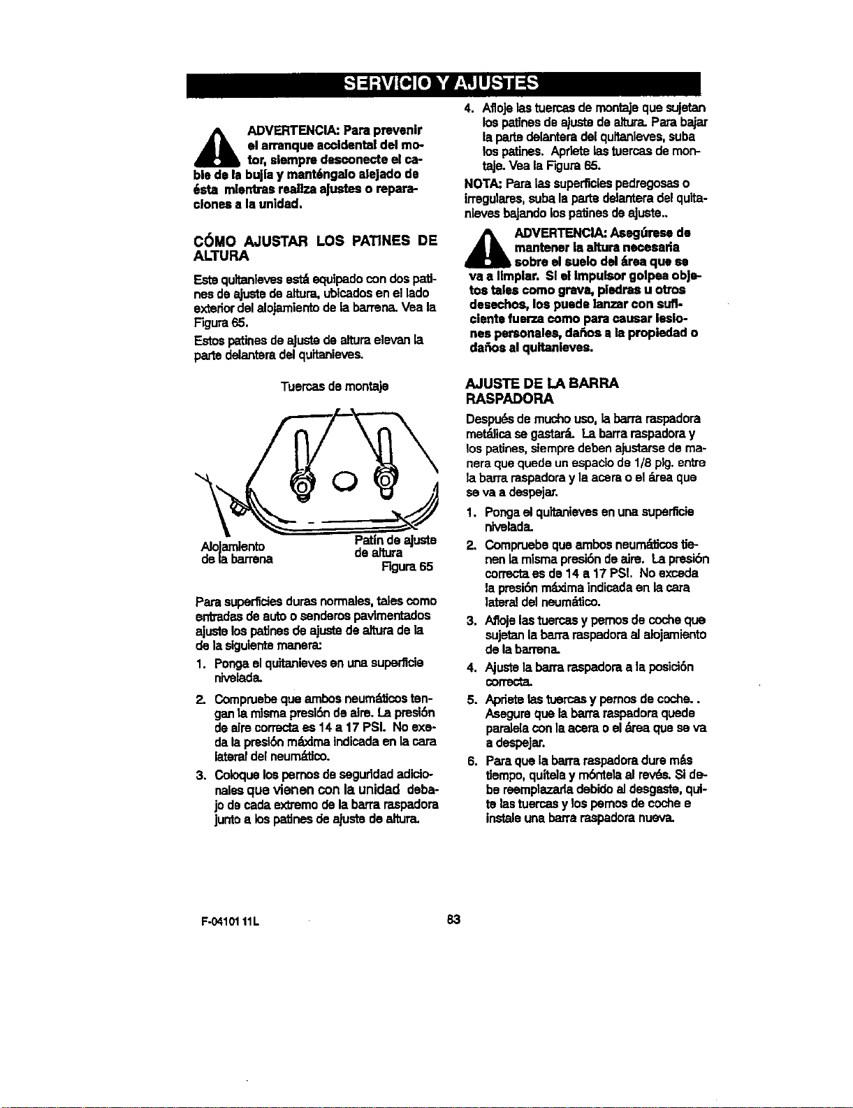
ADVERTENCIA:Para prevenlr
el arranque accidentaldel mo-
tor,slempredesconecteelca-
ble dola bujlay mant6ngaloalejado do
6sta mlontrasreanzaaJusteso repara-
clonesa la unldad.
C6MO AJUSTAR LOS PATINES DE
ALTURA
Estequltanlevesest_equipadocondospati-
nesdeajustedealtura,ublcadosen ellado
extedordelalojamientodelabarrena.Vea la
F,_ura65.
EstospatinesdeaJustedealturaelevanla
partedelanterade]quitanieves.
Tuercas de montaje
Pat|nde ajuste
AloJamlento de altura
delabarrena
Rgura65
Parasuperficiesdurasnormales,talescomo
enb'adasdeautoosendemspavlmentados
ajustelospatinesdeajustedeafturadela
delasiguientemanera:
1. Pongaelquitanlevesenunasuperficie
nivelada.
2. Compruebeque ambosneum_cos ten-
ganla mlsmapres|bndeaim. Lapresibn
deaimcormcP,a es 14 a 17 PSI. Noexe-
dalapresi6nm_txJmaindicadaenla cara
lateraldelneum_dJco.
3. Coloquelospernosdeseguddadadicio-
nalesque vienen con la unidad deba-
jodecadaextremodelabarraraspadora
juntoa lospatJnesdeajustedeeltura.
4. AfloJelastuercasdemontajeque sujetan
lospatJnesdeajustedealtura.Parabajar
lapadsdelanteradelquitanleves,suba
lospatines.Apdetelastuercasdemon-
taJe.Vea la Figura65.
NOTA:Paralas superficiespedregosaso
irregulares,subalapartedelanteradelquita-
nlevesbaJandolospatJnesdeaJuste..
_b DVERTENCIA:Asegdrese de
mantenerlaaltura necesada
sobreel suelodid&reaqua so
va a I|mplar. Sl el impulsorgolpeaobje-
tos talescomo grava, pledrasu otros
desechos, los puedelanzarcon sufl-
clentefue_.a como para causar leslo-
nespersonales,dahosa la propledado
dafiosal quitanieves.
AJUSTE DE LA BARRA
RASPADORA
Despu_.sdemuchouso,labarrarasp,,dora
met_licasegasta_ Labarraraspadoray
lospatines,stemprede'Denajustarsedema-
neraquequedeunespaCiode 1/8pig.entre
la barraraspadoray la acera,oel _'ea que
se va a despejar.
1. Pongaelquitanievesenunasuperficie
nivelada.
2. Compruebequeambosneum_'tJcostJe-
nenlamismapresi6ndeaire. Lapresibn
correctaes de 14 e.17 PSL No exceda
la presl6nm=L_dmaindicadaen lacma
lateraldelneum_ico.
3. Aflojelastuercasy pernosdecocheque
sujetanlaban'araspadoraalalojamiento
delabarrena.
4. Ajustela barmraspadoraa la posici6n
correcta.
5. Apdetelastuercasy pemosdecoche..
Asegurequelabarraraspadoraquede
paralelaconlaaceraoel_'ea que seva
adespeJar.
6. Paraquelabarraraspadoradurem_s
tlempo,quitelay m6nte_al rev6s.SIde-
bereemplazarladebidoaJdesg=Lqte,qui-
te lastuercasy lospemosde coche•
instaleunabarraraspadoranueva.
F-04101 11L 83

COMO DESMONTAR LA
CUBIERTA PROTECTORA
Pare acceder ala buj{a es necesado
quitar la cubierta protectora:
1. Quite el estrangulador (vea la
Figure 66).
2. Saque la ,ave de seguridad.
3. Quite los tornlllos de montaJe
(Figure67).
4. Retire cuidadosamente la cubierta
protectora. Aseg_rese de que la
manguera det bot6n cebador y el
cable de ignickSnpermanezcan con-
ectados.
5. Ahora se puede alcanzar la bujfa.
6. Pare instalar la cubierta protectora,
aseg,',rese de que la manguem del
bot6n cabador y el cable de lgniciSn
est6n conectados.
7. Monte la cubierta protectora en el
motor y fijela con los tom,los de
montaje (vea la Figure 67).
8. Conecte el estrangulador ala vadlla
del estrangulador en el carburador
(F-,3ura68 y F'igura69). Asegdrese
de que el estmngulador est6 Insta-
lado correctamente. SI no Io est_ el
estrangulador no funcionar_
9. Insta]e la Ilave de seguridad.
Cubierta
protectora
Bujia
Estragulador
Tomillosdemontaje
Estranguladol VarHlad_
estragulador Figure68
tlave de
F-O410111L
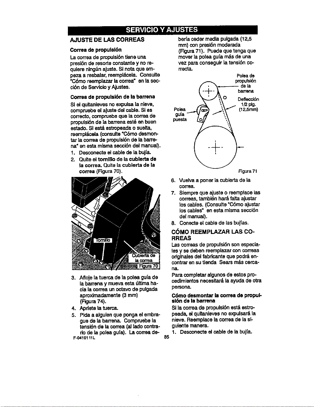
AJUSTE DE I.AS CORREAS
Correa de propulsl6n
La correa de propulsibntiene una
presi6n de resorts constants y no re-
quiem ningdn ajuste. SI note que em-
peza a resbalar, reempl_tceta. Consults
"C6mo reemplazar la correa" en la sec-
ci6n de Servicio y Ajustes.
Correa de propulsl6n de la barrena
Si el quitanieves no expulsa la nieve,
compruebe el ajuste del cable. Si es
correcto, compruebe que la correa de
propulsi6n de la barrena est6 en buen
estado. Si est_ estropeada o suelta,
mempl_¢ela (consults=C6mo desmon-
la correa de propulsi6n de la barre-
ha" en esta misma secci6n del manual).
1. Desconecte el cable de la bujfa"
2. Quite el tornillo de la cublerta de
la correa. Quite la cubierta de la
correa (Figura 70).
3. AfloJela tuerca de la polea gu|a de
la barrana y mueva esta 01tima ha-
cia la correa un octavo de pulgeda
aproximadamente (3 rnm)
(F' ura74).
4. Apriete la tuerca.
5. Pida a alguien que ponga el embra-
gue de la barrena" Compruebe la
tansi6n de la correa (aJlado contra-
rio de la polea gu|a). La oorrea de-
F-0410111L
berra oeder media pulgada (12,5
mm) con presi6n moderada
(Figura 71). Puede que tenga que
mover la polea gu[a m&s de una
vez para conseguir la tansi6n co-
rrecta"
Poleade
.,. pmpulsibn
/ de=a
_,,_ I/2plg.
Po,ea (IZ,Smm)
guta { f ",,_
puesta ._o "\
Figum 71
6. Vuelva a poner la cubierta de la
iDorrea"
7. Siempre que ajuste o reemplace las
correas, tambi_n har_ falta ajustar
los cables. (Consults =C6mo ajustar
los ca,biBs" an esta misma secci6n
del manual).
8. Conecte el cable de las bujIas.
C6MO REEMPLAZAR LAS CO-
RREAS
Las correas de propulsi6n son especia-
les y se deben reemplazar con correas
originales del fabdcante que podr_ en-
contrar en su tienda Sears m_Lsoema-
ha"
Pare completer algunos de estos pro-
cedimientos necesitar_ la ayuda de otra
persona.
C6mo desmontar Is €orraa de propul-
ei6n de la barrena
SI la correa de pmpulsi6n esterestm-
peeda, el quitanieves no expulsar&la
nieve. Reemplace la correa de la si-
guiente manera"
1. Desconecte el cable de la bujZ'a.
85
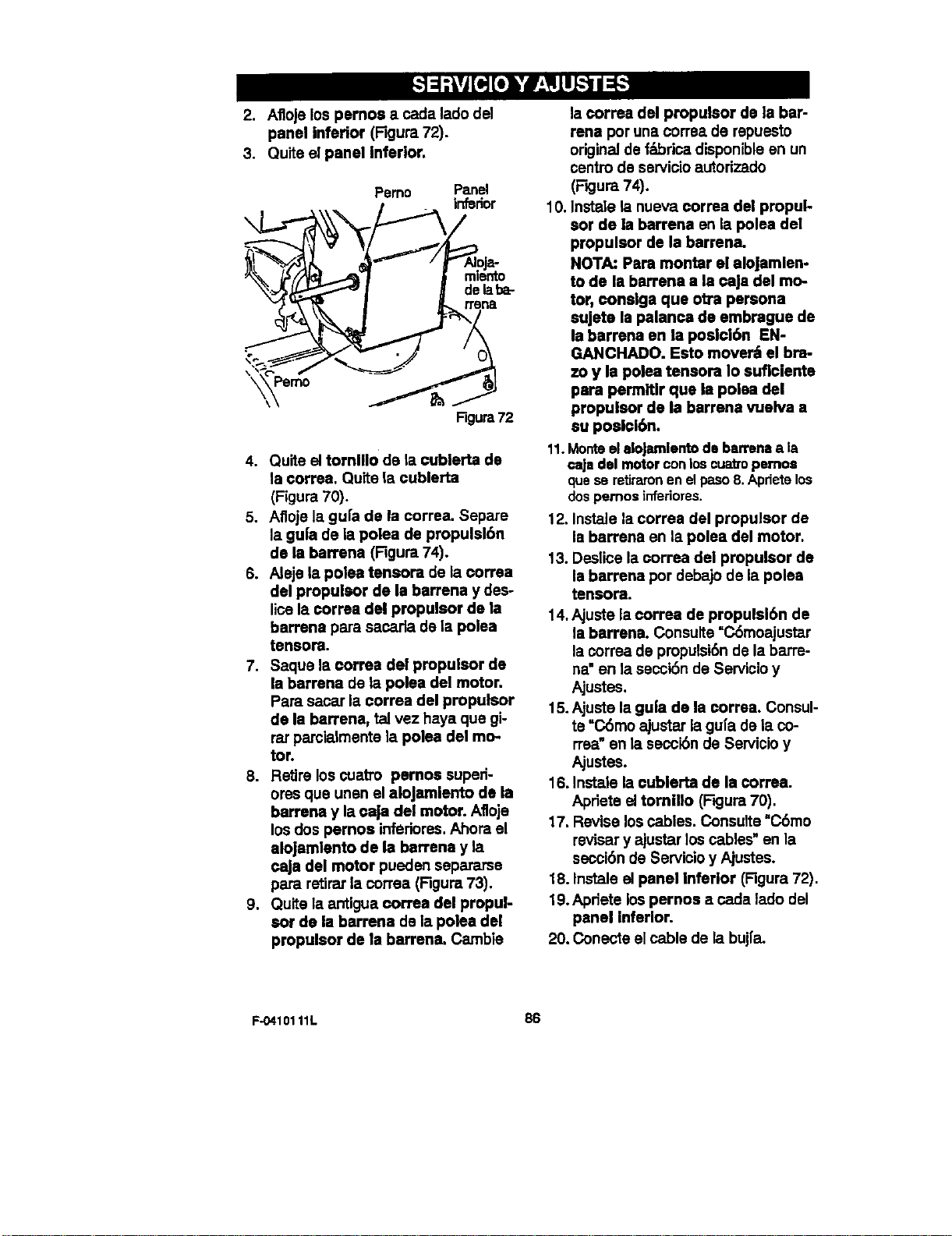
2. Afloje los pernos e cada lado del
panel inferior (Figura 72).
3, Quite el panel inferior.
\
Pemo Panel
inferior
Pemo
\\
Rgura72
4. Quits el tornlll0 de la cublerta de
la correa. Quite la cublerta
(Figure 70).
5. Afloje la gufa de la correa, Sepate
la gu|a de la poise de propulsl6n
de la barrena (F'igura74).
6. Aleje la poise tensora de la eorrea
del propulsor de la barrena y des-
lice la ¢orrea del propulsor de la
barrena pare sacada de la polea
tensora.
7. Saquela correa del propulsor de
la barrena de la polea del motor.
Pare sacat la correa del propulsor
de la barrena, tel vez haya que gi-
rat parcielmente la polea del mo-
tor.
8. Retire los cuatm pernos suped-
ores qua unsn el aloJamiento de la
barrena y la eaja del motor. Afloje
los dos pernos inferiores.Ahora el
alojamlento de la barrena y la
caJa del motor pueden sepamrse
para retirat la correa (Figure 73).
9. Quite la antigua correa del propul-
sot de la barrena de la poise del
propulsor de la barrena. Cambie
la correa del propulsor de la bar-
rena por una correa de rspuesto
original de f_brica disponibleen un
centro de servicio autodzado
(Figure 74).
10. Instals la nueva correa del propul-
eor de la barrena en la poise del
propulsor de la barrena.
NOTA: Pare montar el alojamlen-
to de la barrena a la ¢aja del mo-
tor, conslga que ob'a persona
sujeta Is palanca de embrague de
la barrena en la posici6n EN-
GANCHADO. Esto mover_ el bra-
7.oy la poise tensora Io suflcienta
para permitlr qua la poise del
propulsor de la barrena vuelva a
su poslcl6n.
11.Monteelelo|amlento de barrenaala
caja del motorconloscuatropemos
quese retiraronenelpaso8.Apriete los
dospemos inferiores.
12. Instals la correa del propulsor de
la barrena en la polea del motor.
13. Deslice la correa del propulsor de
la barrena por debajo de la poise
tensora.
14. Ajuste la oorrea de propulsl6n de
la barrena. Consuite =C6moajustat
la correa de propulsi6n de la batre-
ha" en la secci6n de Servicio y
Ajustes.
15.Ajuste la gula de la correa. Consul-
te "C6mo ajustat la gu[a de la co-
rrea"en la secci6n de Servicio y
Ajustes.
16. Instele la cublerta de la correa.
Apdete el tornillo (Rgura 70).
17. Revise los cables. Consuite =C6mo
revisar y ajustar los cables" en la
secci6n de Servicio y Ajustes.
18. Instals el panel Inferior (Figure 72).
19.Apdete los pernos a cada lado del
panel inferior.
20. Conecte el cable de la buj|a.
F-0410111L 86
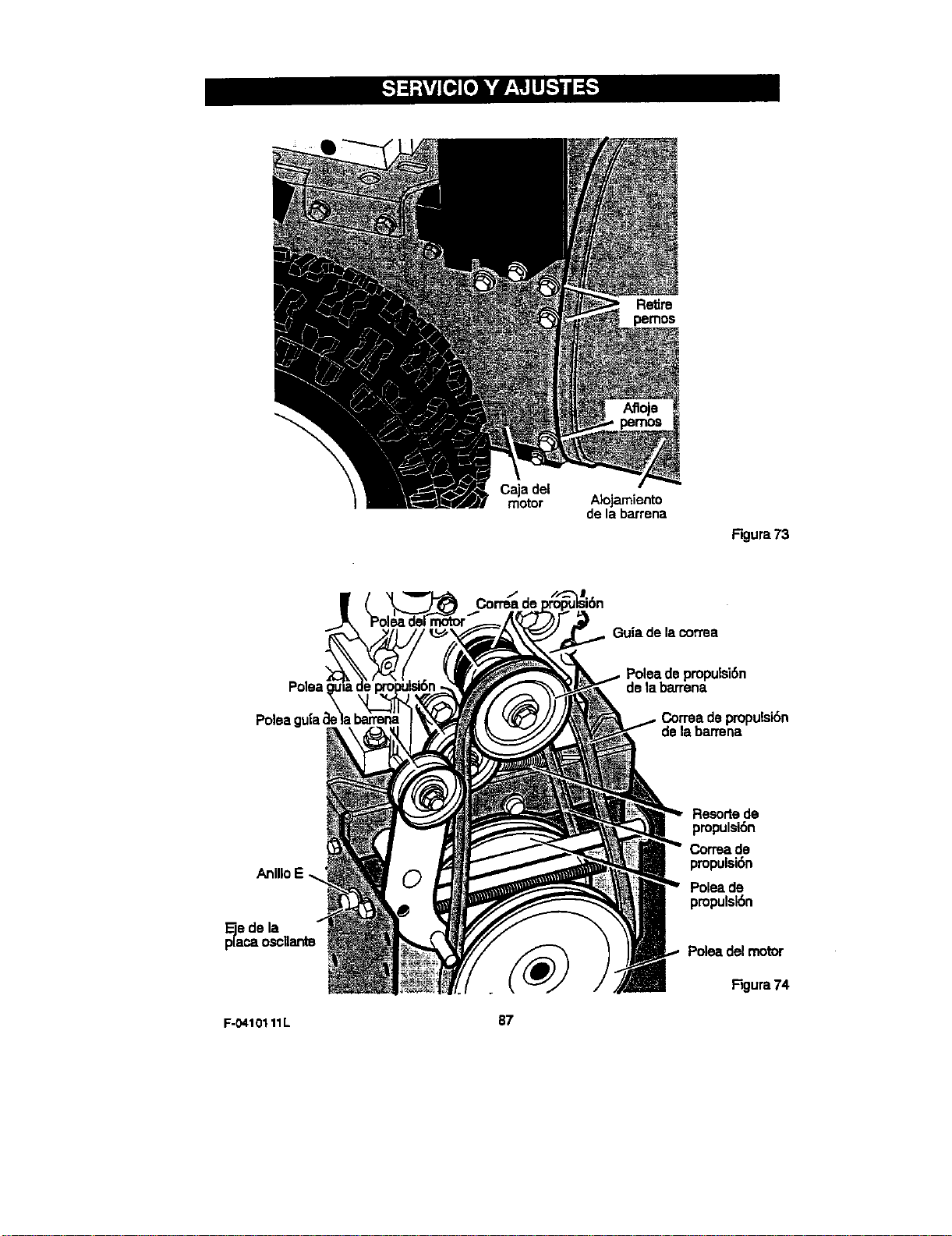
Caja del
motor
Abjamiento
de la barrena
Figura73
Corma de
Guia de la correa
Polea
Poleaguiaae
Polea depmpulsi6n
de labarrena
Correadepropuisi6n
delabarrena
de la
F-O410111L
87
Resortede
pmpulsibn
Correade
propulsi6n
Poleade
propulsl6n
Polea del motor
Figura 74
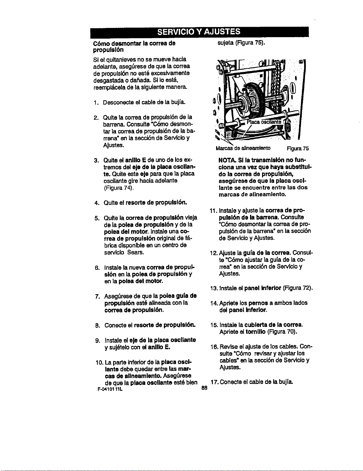
Cbmo desmontar la correa de
propulsi6n
Si el quitanieves no se mueve hacia
adelante, aseg_rese de que la correa
de propulsi6n no est6 excasivamente
desgastada o dafiada. Si Io est,,
reempldcala de la siguiente maner_
1. Desconecte el cable de la buj|a.
2. Quite la correa de pmpulsi6n de la
barrena. Consuite "C6mo desmon-
tar la correa de pmpulsi6n de la ba-
rrena" en la seccibn de Servicio y
Ajustes.
3. Quite el anillo E de unode los ex-
tremos del ejo de la place oscilan-
te. Quite este eje para que la place
oscilante gire hacia adelante
(Figure 74).
4. Quite el resorte de propulsl6n.
5. Quite la correa de propulsi6n vieja
de la polea de propulsl6n y de la
polea del motor, lnstale una eo-
rrea de propulsibn originalde f_.-
brica disponlble en un cantro de
servicio Sears.
6. Instale la nueva correa de propui-
sibn en la polea de propulsi6n y
en la polea del motor,
7. Asegt_resede que la polea gu|a de
propulsibn est6 allneada con la
correa de propulsi6n.
sujeta (Rgura 75).
Mamas de alinearnlento Figure 75
NOTA. Sl la transmlsi6n no fun-
clone una vez que haya substitul-
do la ¢orrea de propulsi6n,
aseg(Irese de que la place osci-
lante se encuentre entre las dos
marcas de alineamlento.
11. Instale y ajuste la correa de pro-
pulei6n de la barrena. Consulte
=C,6modesmontar la correa de pro-
pulsi6n de la barrena"en la secci6n
de Servicio y Ajustes.
12. Ajuste la gu|a de la correa. Consul-
te "C.6moajustar la gu[a de la co-
tree" en la secoi6n de Servicio y
Ajustes.
13. Instale el panel Inferior (Figure 72).
14.Apriete los pemos a ambos lados
del panel inferior.
8. Conecte el resorte de propulsi6n.
9. lnstale el eje de le placa oscliante
y suj6telo con el anlllo E.
10. La parte inferiorde la place oscl-
lante debe quedaLrentre los mar-
cas de ellneamlento, Asegt_mse
de que la place oscllante est6 bien
F-0410111L
15. Inst_e la cublerta de la correa.
Apriete el tomillo (Figure 70).
16. Revise el ajuste de los cables. Con-
suite "C6mo revisery ajustar los
cables" en la secci6n de Servicio y
Ajustes.
17. Conecte el cable de la buj[a.
88
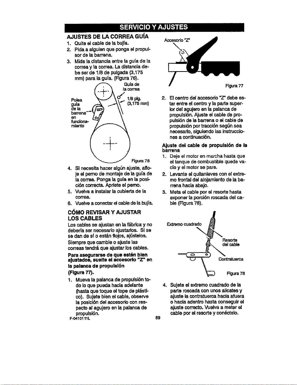
AJUSTESDELA CORREAGUJA
1. Quiteelcabledele bujfa.
2. Pida a alguian que ponga el propul-
sor de la barrena.
3. Mida la distancia entre la gufa de la
correa y la correa. La distancia de-
be ser de 1/8 de pulgada (3,175
ram) para la gufa. (Figura 76).
/ _, GuIjdrn:
Polea _ _al/Splg •
0ufe - (3,tZS m)
d,la - \\
barrena'-r_/ \\
en o
miento I ___"- .
Figure 76
4. Si necesita hacer alg_n ajuste, aflo-
je el pemo de montaje de la gu[a de
la correaLPonga la gufa an la posi-
ci6n correcta. Apriete el pemo.
5. Vuelva a instalar la cubierta de la
oorrea.
6. Vuelve a conectarel cable de la bujIa.
COMO REVISAR Y AJUSTAR
LOS CABLES
Los cables se ajustan en la _bdca y no
deber[a ser necesario ajustados. Si se
se dan de s( o est_mflojos, aj,_stelos.
Slempre que camble o ajuste las
coffees tend_ que ajustar los cables.
Para asegurarse de que est6n bien
aJustados, suelte el accesorio "Z" en
ta palanca de propulei6n
(Figure 77).
1. Mueva la palanca de propulsi6n to-
do le que pueda hacle adelante
(haste que toque el tope de pl_tl-
co). Sujete bien el cable, observe
la posici6n del accesorio con res-
pecto at agujem en la pelanca de
pmpulsi6n.
F-0410111L
Accesorio "Z"
Rgura 77
2. El cantro del accesorio "Z" debe es-
tar entre el centro y la parte super-
ior del agujem an le palanca de
pmpulsi6n. Ajuste el cable de pro-
pulsibn de la barrena o el cable de
propulsi6n portracci6n seg,_nsea
necesado, siguiendo las instmccio-
nes a continuaci6n.
Ajuste del cable de propulsl6n de la
barrena
1. Deje el motoren marcha hasta que
el tanque de combustible quede va-
ci'oy el motor se pare.
2. Levante el quitanleves con el extre-
mo frontal del alojamlento de la ba-
rrena haela abajo.
3. Meta el cable por el resorte haste
exponsr la porci6n roscada del ca-
ble (Rgura 76).
89
Exbemocuadrado
delcable
Contratuerca
Rgura78
4. Sujete el extremo cuadrado de la
parte roscada con unos alicates y
ajuste la contratuerca hecia afuem
o haela adantro haste conseguir el
ajuste correcto. Vuelva a meter el
cable por el resorte y condctelo.
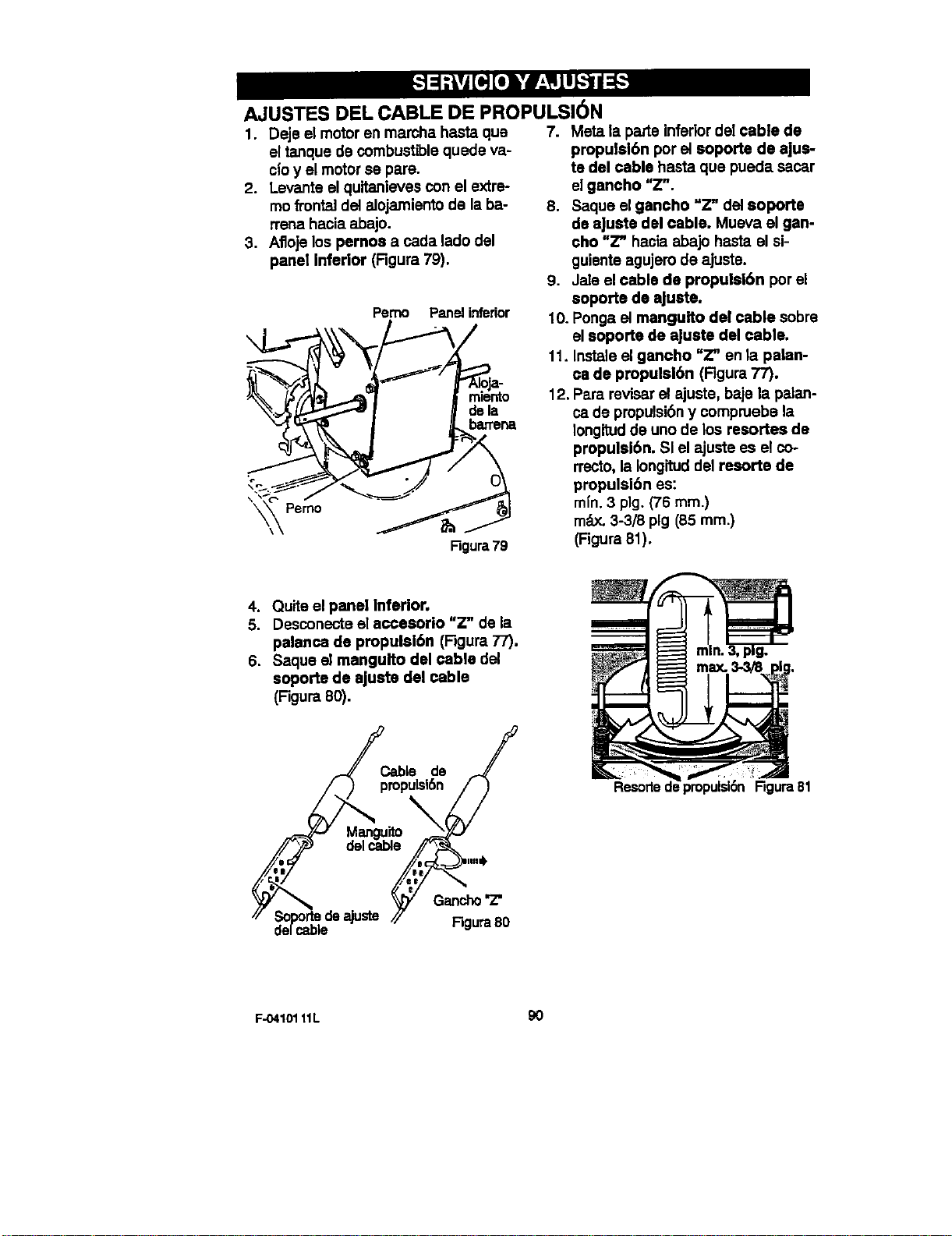
AJUSTES DEL CABLE DE PROPULSI6N
1. Deje el motor en mamha haste qua
el tanque de combustible quede va-
cloy el motor se pare.
2. Levante el quitanieves con el extre-
mo frontal del alojamiento de la ba-
rrena hacia abajo.
3. Afloje los pernca a cada lado del
panel inferior (Rgura 79).
Pemo Panel infedor
o , _l_arrana
Ngura 79
7. Mete la parte infedor del cable de
propulsl6n por el soporte de ajus-
te del cable haste que pueda sacar
el gancho "Z".
8. Saque el gancho =Z" del soporte
de eJuste del cable. Mueva el gan-
cho "Z" hacia abajo hasta el si-
guiente agujero de ajuste.
9. Jele el cable de propulsibn por el
soporte de aJuste.
10. Ponga el manguito del cable sobre
el soporte de aJuste del cable.
11. Instele el gancho "Z" en la palan-
ca de propulslbn (Rgura 77).
12, Pare reviser el ajuste, baje la palan-
ca de propulsiSny compruebe la
Iongitudde uno de los resortes de
propulsi6n. SI el ajuste es el co-
rrecto, la Iongituddel resorts de
propulsibn es:
mfn. 3 pig. (76 ram.)
mdx. 3-3/8 pig (85 ram.)
(Figure 81).
4. Quite el panel Inferior.
5. Desconecte el accesorio "Z" de la
palanca de propulaibn (Rgum 77).
6. Saque el mangulto del cable del
soporte de ajuste del cable
(Rgura 80).
pC,able de /
mpulsi6n / )
Figura80
€'elc_te
Resorke Figure81
F-04101 11L 90
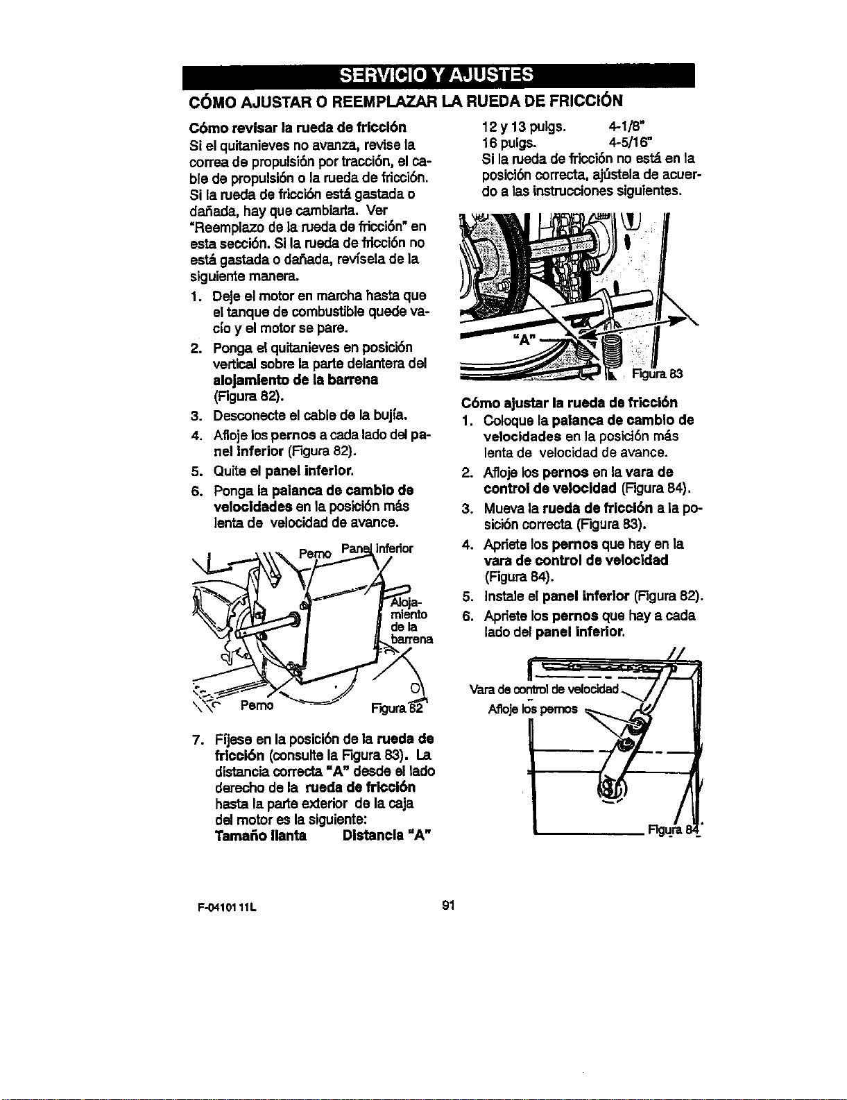
C6MO AJUSTAR 0 REEMPLAZAR LA RUEDA DE FRICCI(_N
C6mo revisar la rueda de frlcci6n
Si el quitanieves no avanza, revise la
correa de pmpulsi6n por tracoi6n, el ca-
ble de propulsi6n o la rueda de fricci6n.
Si la rueda de fricci6n est_ gastada o
da_ada, hay que cambiarla. Ver
"Reemplazo de la meda de fl'icoi6n"en
esta secoi6n. Si la rueda de fricci6n no
est_ gastada o da_ada, revfsela de la
siguiente manera.
1. Deje el motor en mamha hasta que
el tanque de combustible quede va-
c|o y el motor se pare.
2. Ponga el quitanieves en postci6n
vertical sobre la parte delantera del
alojamlanto de la barrena
(Figura 82).
3. Desconecte el cable de la bujfa.
4. Afloje lospernos a cada ladodel pa-
nel Inferior (Figura 82).
5. Quite el panel inferior.
6. Ponga la palanca de cambio de
velocldadea en la posicibn m_Ls
lenta de velocidad de avanca.
. _mo Pan_, inferior
7. Fijese en la posici6n de la rueda de
frloci6n (consulte la Figure 83). La
distancia correcta =A" desde el lado
derecho de la rueda de fr_ci6n
hasta la parte exterior de la caja
del motor es la siguiente:
Tama6o Ilanta Dlstanola "A"
12 y 13 pulgs. 4-1/8"
16 pulgs. 4-5/16 °
Si la meda de fricoi6nno estd en la
posioibncorrecta, ajL_stelade aouer-
do alas instmcoiones siguientes.
C6mo ajustar la rueda de fTIcci6n
1. Coloque la palanca de camblo de
vetocldades en la poelci6nm_,s
lenta de velocidad de avarice.
2. Afloje los pernos en lavara de
control de velooidad (Figura 84).
3. Mueva la rueda de frioci6n a la po-
sici6ncorrecta (Figura 83).
4. Apriete los pernoa que hay en la
vara de control de velocldad
(Figura 84).
5. Instale el panel inferior (Figura 82).
6. Apdete los pernos que hay a cada
lado del panel inferior.
F-04101 11L 91
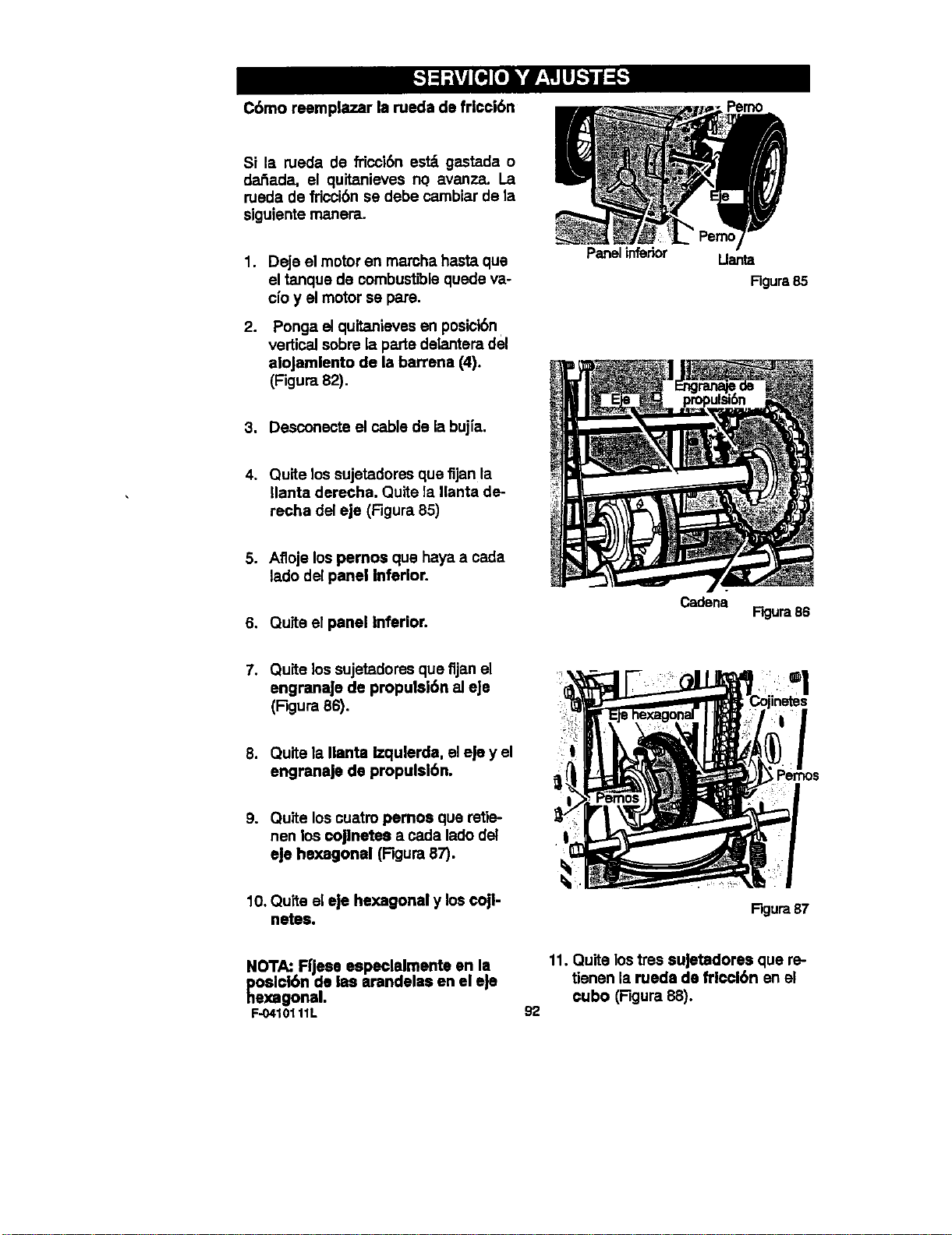
C6mo reemplazar la rueda de fricci6n
Si la rueda de fricci6n est_ gastada o
dar_ada, el quitanieves nq avanza. La
rueda de fdcel6n se debe cambiar de la
siguiente manera.
1. Deje el motor an mamha hasta que
el tanque de combustible quede va-
cfoy el motor se pare.
2.
Ponga elquitanieves en posict6n.
vertical sobre la parte delantera del
alojamiento de la barrena (4).
(Figura 82).
Panelinfedor
Llanta
Rgura85
3. Desconecte el cable de la bujfa.
4. Quite los sujetadores qua fijan la
Ilanta derecha. Quite la llanta de-
recha del eje (Figura 85)
5. Afloje los pemos qua haya a cada
lado del panel Inferior.
6. Quite el panel Inferior.
Cadena
F'_ur a 86
7. Quite los sujetadores que fijan el
engranaJe de propulsl6n aJeJe
(Rgura 86).
8. Quite la Ilanta Izqulerda, el eJey el
engranaje de propulsibn.
9. Quite los cuatm pemos qua retie-
nen los coJlnetea a cada lado del
eJe hexagonal (Figura 87).
10. Quite el eje hexagonal y los cojl-
netes.
Figura87
NOTA: Ffjese especlalmente en la
poslcl6n de las arandelas en el eJe
hexagonal.
F..0410111L
92
11. Quite los tres suJetadores qua re-
tienen la rueda de friccl6n en el
cubo (Figura 88).
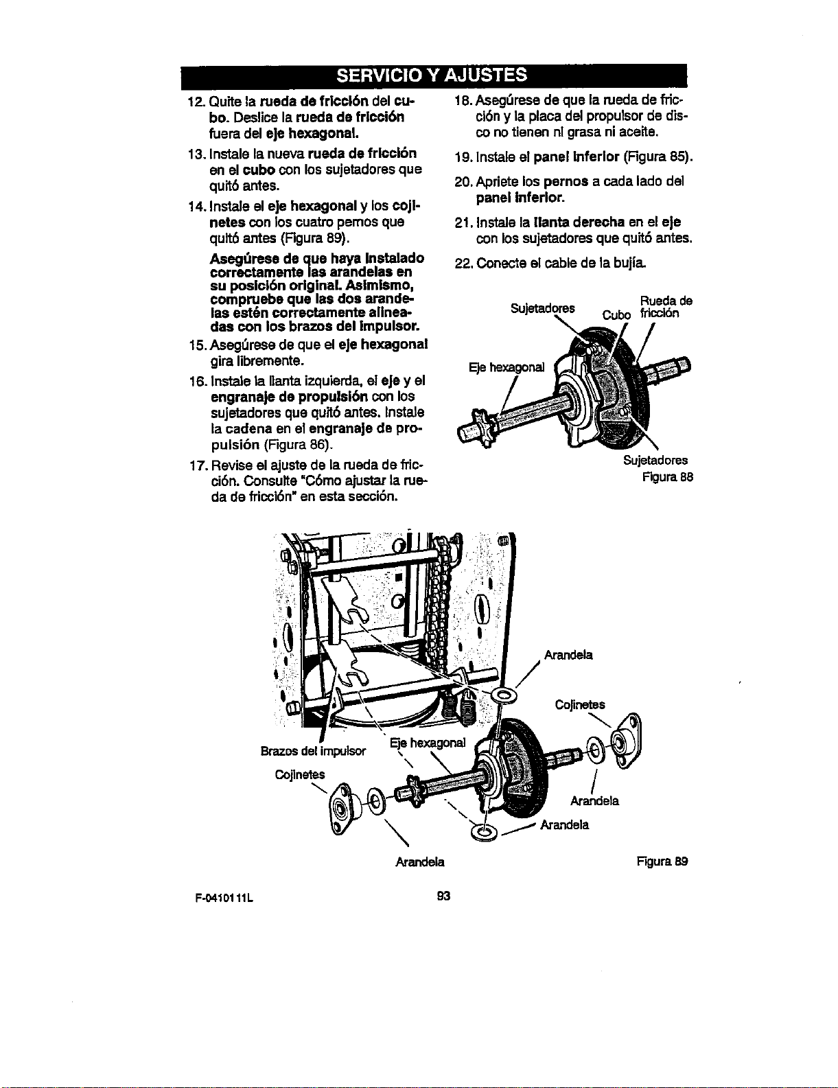
12.Quitelaruedadefdccl6ndelcu-
bo.Deslicelaruedadefricoi6n
fueradelHehexagonal.
13.Instalelanuevaruedadefrlcci6n
enelcuboconlossujetadoresque
quit6antes.
14.Insteleelejehexagonalyloscojl-
netesconloscoatro pemos que
quit6 antes (Figura 89).
Aseg_rese de que haye Instalado
correctamente/as arandelas en
su posl¢i6n originaL Aslmismo,
compruebe que les dos arande-
las est6n correctamente allnea-
das con los brazos del impulsor.
15. Asegt_rese de qua el eje hexagonal
gira libremente.
16. Instele la flanta izquierda_el eJey el
engranaje de propulsi6n con los
sujetadores que quit6 antes. Instate
la cadena en el engranaje de pro-
pulsi6n (Figura 86).
17, Revise el ajuste de la rueda de fdc-
ci6n. Consulte =C6moajustar la rue-
da de fricci6n"an esta secci6n.
18.Aseg_rese de que la rueda de _c-
ci6n y la placa del propulsor de dis-
co notienen nl grasa ni aceite.
19. lnstele el panel Infedor (Figura 85).
20, Apfiete los pernos a cada lado del
panel inferior.
21. Instale la Ilanta derecha en el eje
con los sujetadores que quit6 antes.
22. Conecte el cable de la bujl"a.
Ruedade
Sujetadores Cubo fricci6n
Ejehexagonal
Sujetadores
Figura88
Br_os delimpulsor ,,
X
Cojlnetes
\
Arandela
Arandela
CoJinetes
Arandeta
Figura89
F-0410111L 93
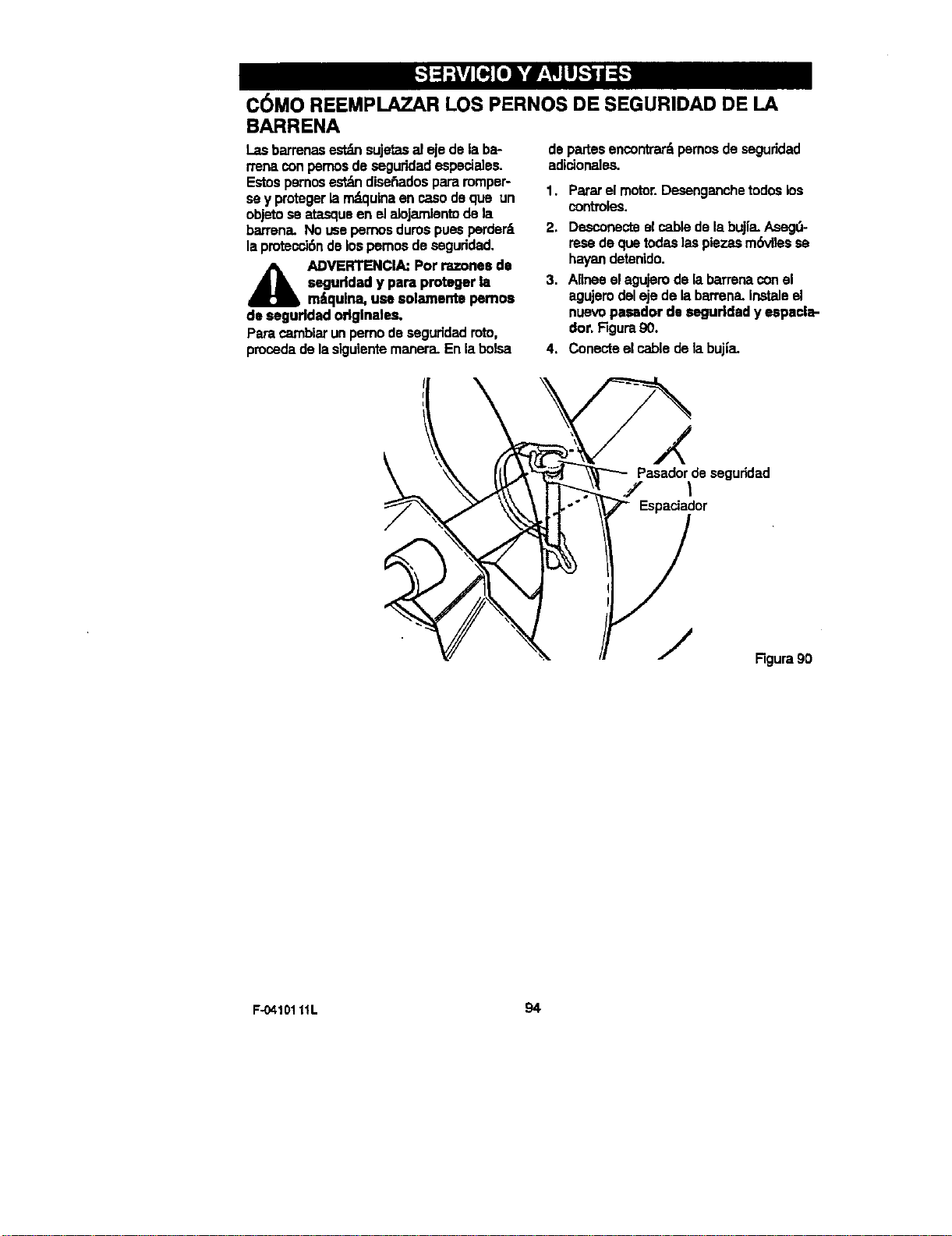
C6MO REEMPLAZAR LOS PERNOS DE SEGURIDAD DE LA
BARRENA
I_asbarrenas_ sujetasaleje delaba-
rrenaconpemosdeseguridadespeciales.
Estospsrnosest_ dise_adospararomper-
sey protegerlam_quinaen ca,sodeque un
objetose atasqueen elalojamlentodela
barrena.Nousepemosdumspuesperder6
lapmtecci6ndelospemosdeseguddad.
A DVERTENCIA:Potrazonesde
seguddady para protegerla
m_qulna,use solamentepemos
deseguddadodglnales.
Paracambiarunpemodeseguddadroto,
procedade lasigulentemanera.Enlabolsa
departesencontrar_pemosdeseguridad
adicionales.
1. Pararelmotor.Desenganchetodoslos
contToles.
2. Desconecteelcabledelabujfa.Aseg_-
resedequetodaslaspiezasm(_,llesse
hay'andetenido.
3. Alineselagujerodelabarrenaconel
agujemdelejedelabarrena.Instaleel
nuevopasador desegurldady espacla-
dot.F_jura90.
4. Conecteelcabledelabuj[a.
Pasadordeseguridad
/ I
Espaciador
Rgura90
F-04101 11L 94
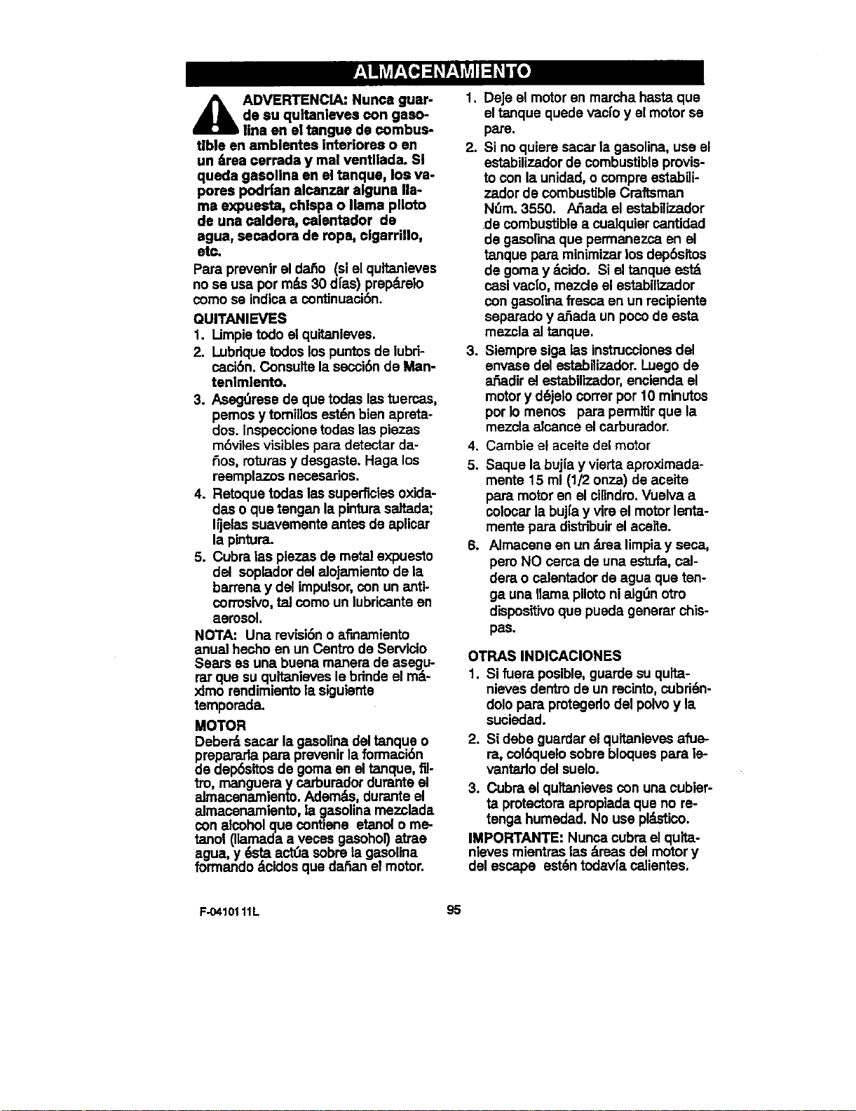
_lb DVERTENCIA: Nunca guar-
de su qultanleves €on gaso-
line en el tangue de €ombus-
tible en amblentes interiores o en
un/,rea cerrada y mal ventllada. Sl
queda gasoline en el tanque, los va-
pores podr|an alcanzar alguna lla-
ma expuesta, chispa o llama plloto
de una ¢aldera, calentador de
agua, secadora de rope, ¢lgarrillo,
etc.
Para prevenir el da_o (si el quitanieves
no se usa por m_ 30 d[as) prep_elo
como sa indica a conUnuaci6n.
QUITANIEVES
1. I impie todo el quitanieves.
2. Lubrique todos los puntos de lubri-
caci6n. Consulte la secci6n de Man-
tenimlento.
3. Asegt_rese de qua todas las tuercas,
pemos y tomillos est0n bien apreta-
dos. Inspeccione todas las piezas
m6viles visibles pare detecter da-
_os, roturas y desgaste. Haga los
reemplazos necesarios.
4. Retoque todas las superficies oxida-
des o que tengan la pinturasaltada;
Ifjalas suavemente antes de aplicar
la pintura.
5. Cubra las piezas de metal expuesto
del soplador del alojamiento de la
barrena y del impulsor,con un anti-
corrosivo, tal como un lubricante en
aerosol,
NOTA: Una revisi6n o afinamiento
anual hecho en un Centro de Servicio
Sears es una buena manera de asegu-
rat que su quita=nievesle brinde el m_-
ximo rendimiento la siguiente
temporada.
MOTOR
Deber_ sacar la gasolina del tanque o
preparada pare prevenir la formaci6n
de dep6sitos de goma en el tanque, ill-
tin, manguera y carburador durante el
almacenamiento. Ademds, durante el
almacenamiento, la gasolina mezclada
con alcohol que contiene etanol o me-
tanol (llamada aveces gasohol) atrae
agua, y 6sta actua sobre la gasolina
formando dcidos qua da_an el motor.
1. Deje el motor en marcha hasta qua
el tanque quede vaci'oy el motor se
pare.
2. Si no quiere sacar la gasolina, use el
estabilizador de combustible provis-
to con la unidad, o compre estabili-
zador de combustible Craftsman
N_m. 3550. /_ada el estabilizador
de combustible a cualquier cantidad
de gasolina qua permanezca en el
tanque pare minimizer los dep6sitos
de goma y _cido. Si el tanque est_
casi vaclo, mezcle el estabilizador
con gasoline fresca en un recipiente
separado y a_ada un poco de esta
mezcla el tanque.
3. Siempre siga las instruccionesdel
envase del estabilizador. Luego de
afiadir el estabilizador, encienda el
motory d6jelo correr por 10 minutos
per Io menos para perm_r que la
mezcla alcance el carburador.
4. Cambie el aceite del motor
5. Saquela buj[a y vierta aproximada-
mente 15 ml (1/2 onza) de aceite
para motor en el cilindm. Vuelva a
colocar la buj[a y vira el motor lenta-
mente para distribuirel acetie.
6. Almacene en un _=realimpia y see.a,
pero NO cerca de una estufa, oal-
dera o calentador de agua que ten-
ga una llama piloto ni alg_n otto
dispositivo que pueda generar chis-
pas°
OTRAS INDICACIONES
1. Si fuera posible, guarde su quita-
nieves dentro de un mcinto, cubri_n-
dolo para pmtegedo del polvo y la
suciedad.
2. Si dabs guarder el quitanieves afue-
re, col0quelo sobre bloques para le-
vantado del suelo.
3. Cubra el qultanieves con una cubier-
ta pmtectora apmpiada qua no re-
tenga humedad. No use pkL_,'tico.
IMPORTANTE: Nunca cubra el quita-
nieves mientras las _eas del motor y
del escape est_n todav[a ca]ientes.
F.O410111L 95
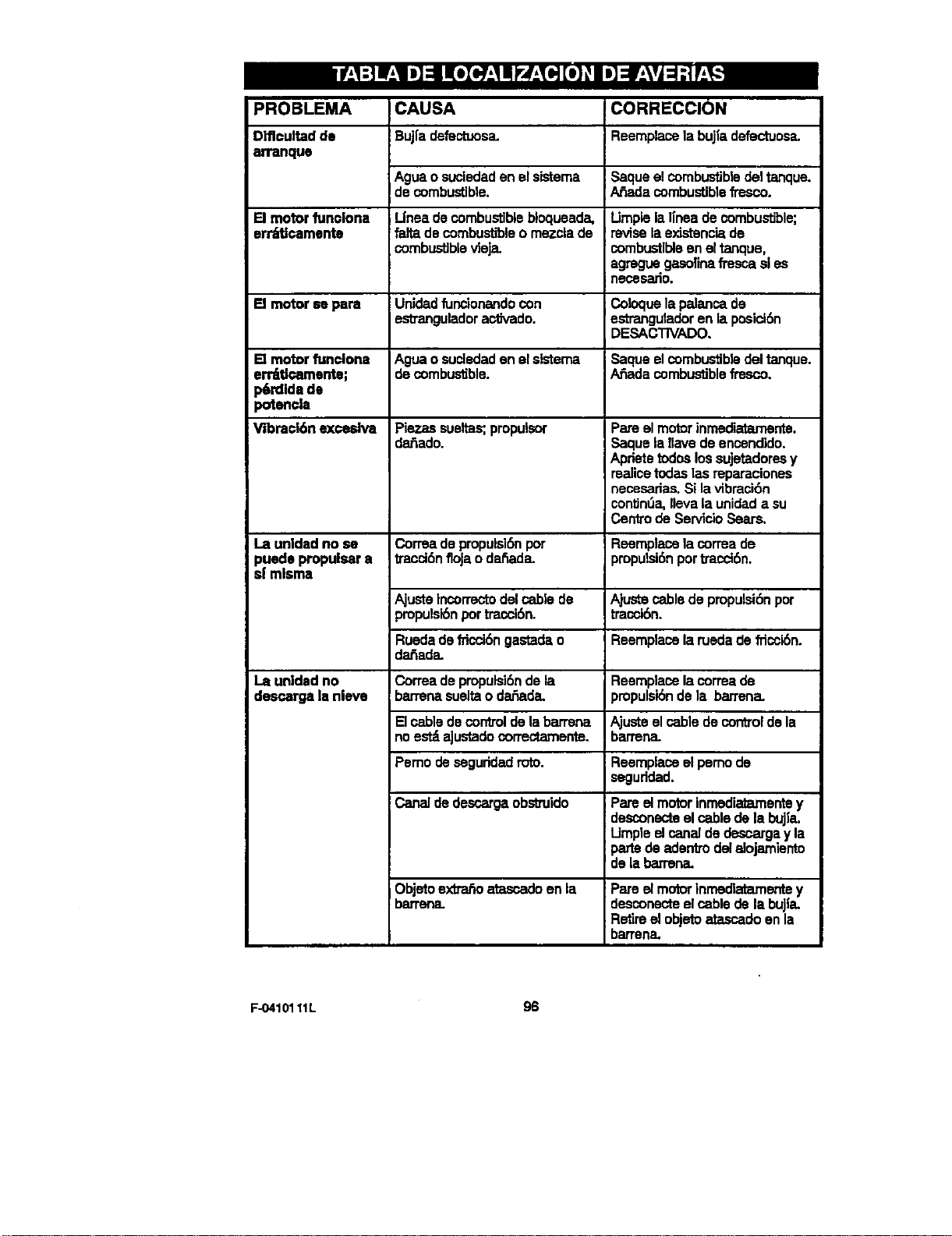
PROBLEMA
Dlflcultadde
arranque
CAUSA CORRECClON
Bujfadefectuosa. Reemplacelabujl'adefectuosa.
Agua o suciedad en el sistema Saque el combus'dbledel tanque.
de combustible. A_da combustible fresco.
El motor funciona Unea de combustible bloqueada, Umple la linea de combustible;
err_atlcamente falta de combustible o mezcla de revise la exJstenc'_de
combustiblevieja, combustible en el tanque,
agmgue gasolina fresca sl es
neces_JiO.
[] motor se para Unidad funcionando con Coloque la palanca de
estmngulador actJvado, estrangulador en la posici6n
DESACTIVADO.
El motor funciona Agua o sucledaclon el slsterna Saque el combustible del tanque.
err_tJcamonte; de combustible. A_ada combustible fresco.
p6rdlda de
potencla
Vibract6n exceslva Plazas sueltas; propulsor Pare el motor inmediatamerrte.
da_ado. Saque ia llave de encendido.
Apdete todos los sujetadores y
realice todas las reparaciones
necesarias. Si lavibraci6n
contJn_ak,eva la unidad a su
Centro de Servicio Sears.
La unldad no se Correa de propulsiSnpot Reemplace la correa de
puede propulsar a I/accidnfloja o dai_ada, proputsi6n portracct6n.
sJmisma
Ajuste Incorrectodel cable de AJustecable de proputsk_npor
propulsi6npor tracci6n, tracci6n.
Rueda de fricci6n gastada o Reemplace la rueda de fficcl6n.
dar3ada.
La unldad no Correa de propulsi6nde la Reemplace la correa de
descarga la nieve barrena suelta o dar3ada, propulskSnde la barrena.
B cable de control de la barrena Ajuste el cable de control de la
no estd aJustadocorrectamente, barrena.
Pemo de seguddad roto. Reemplace el perno de
seguddad.
Canal de desca_ga obstmido Pare el motor inmecliatamentey
desconecte el cable de la bujl'a.
LJmpieel canal de descarga y la
parts do adentm del alojamiento
de la barmna.
Objeto exttar_ atascado en la
barrena.
Pareelmotorinrnedlatamentey
descone_eelcablede labuJla.
Retireel objetoatascadoonla
barrena.
F-0410111L 96
(_lai_na e_a_ _mnte en_ed_ U_s deAm6ricay_dt.)
Sears, Roebuck and Co., U.S.A. (Seem), Junta de Recumos Ambientales de California
(CARB) y Agencla de Proteccl6n Amblental de los Estados Unidos (U.S. EPA)
Declaracl6n de Is Garantla del Slstema de Control de Emisiones (Derschos y
Obllgaciones del Propletarlo de la GarsnUa de Defectos)
LA COBERTURA DE LA _ DEL CON-
TROL DE EMISIONES ES APLICABLE A LOS
MOTORES CIs=_r'IRCADOS QUE HAYAN SI-
DO COMPRADOS EN CALIFORNIA A PARTIR
DE 1995 Y DESPUf:S DE ESTA FECHA, LOS
CUALES SEAN USADOS EN CALIFORNIA, Y
PARA LOS MOTORES CERTIFICADOS Me-
DELOS 1997 EN AD_ QUE SEAN
COMPRADOS Y USADOS EN OTRA PARTE
DE LOS ESTADOS UN|DOS (Y A PARTIR DE
ENERO 1 DE 2001 EN CANADA).
Declamcl6n de IsGarsntlade Defectosdel Slstemade Control de Emisionesde
California,Estados Unldosy Canad4
La JurCadeRecursosAn'blerC_es(CARE;),La
AgenciadeProtecc_nAmbientaldelosEstados
UnidosU.S.E_Ay Sea_ secomplacenenexplt-
cartesla Garantiadel S'Lqtsmade Confrolde
Emisionesdesumotorpeque_omodelo2000en
adelantepare use en terrenossin pavimento
(SORE). En Caffiornla,los nuevosmotores
_ pareusoen terrenossinp_imer_
debenser disefedos,fabricadosy equipados
parecumpSrlosrigumsos_ anti-smog
deJEstado.EncualquierokapartedelosEsta-
dosUrados,losnuevosmotoresde encendido
potchispapareno usoen carreterasmodelos
1997y postefioms,debencurnp&"est_tndaresst-
r_lamsa los_ potlaAgendadePro-
tecci6nAmbientalde losEstadosUnidos(U.S.
EPA).Sea_ debe_ el dstemadecon-
f_oldeemisionesensumot_porlosperiodosde
f_empoistadosabajo,tsnlendoencuerdaqueno
hayahabidoabuso,negl_genc_omardenimien-
tonoapropladoensumotorpeque_opareuso
enterrenossinpavtrrento.
Su sisternade controlde emisionesinclwe
partestalescomoel carburador,elfiltTodeaim
el slstemade encendldo,elrnofley elconverti-
dorcatalftico.Tambi(_npuedeinclu[rconecto-
res y otros conjuntosrelacionadoscon el
sistemadeemisiones.
Siemprequeexistaunacondick_degarant[a,
Searsreparardsumotorpequefio,pareus=)en
terrenossinpavimentosinnlnguncostopare
ustedincluyondoeldlagn6stico,laspartesy la
manodeobra.
Coberlura de la Gamntla de Defectos del Slstema de Control de Emislones Sears
Losmotorespequefiospare use entermnos
sin pavimentose garantJzanrelativoa losde-
fectosde laspartesdelslstemade controlde
emisionesduranteunperlododedosafios,su-
jetoalas provisionesestablecidasabajo.SiaJ-
gunadelaspartesbajocoberturaensumotor
se encuentradefectuosa_laparteser_repara-
da oreemplazadaporSears.
Responsabllldades del Propletario de la Garantie
Como propietariode un motorpequefiopara
uso en terrenossinpavlmento,us-tedas res-
ponsablede que se Ilevea cabo el mantenl-
miento requeddo el cual se indica en sus
Instruccionesde Mantenimientoy Operaci6n.
Searslerecomiendaguardartodossusreclbos
qua cubran el mantenimientoen su motor
pequofiopareusoenten-enossinpavimento,
peruSearsnosolopuedenegarlagarantiapor
lafaltaderecibossinepersuomisi6nalasegu-
rat Isreaflzaci6ndetodoelmantenimientopro-
grarnado.
Noobstante,comepropletartodeunmotorpe-
quefiopare useenterrenoss_npavimento,us-
ted tJonequadamecuentaque Searspuede
negarlela coberturadelagarant[asisumotor
pequefiopareusoenterrenossinpavimentoo
ur_ de susparteshafalladodebidoa abuso,
F-0410111L
negligenda,mantenimientoincorrectoo rnodl-
flcacionesnoapmbadas
Usledes responsablede presentersumotor
pequerlopareuseenterrenossinpavirnentoa
un Distdbuldorde Servlcio AutoriTndoSeam
tanprontoseptesenteelproblema.Lasrepars-
clonesbajogarsntlaindisputablesdebencom-
pletarseen un periodod.etlemporazonable
que nose excedade30 dies.
SI usted_ene algunaspreguntasreladonadas
conlosderschosyresponsabilidadesdelage-
rsntia, debecontactara un Representantede
Se_icio Sears marcando el tel_,fono:
1-414-259-5262.
Lagarant{adeemlsionesas unagarant|ade
defectos.Losdefectossonjuzgadosend des-
empefio normaldeunmotor.Lagarant[anoes-
t_ relacionadaconunapruebadeemisionesen
usa.
97
Pmvbiones de laGarantlade Defectosdel Sistemade Con_ol de EmislonesSears
Las sigulentes son provisionesesdec|ficas m-
la_,as a la Cobertura de Garantla de Defectos
del Sistema de Control de Emisiones. Es una
adici6n de la garantJadel motor Sears para los
motores no-regulados encontrados en los
Instruccionesde Mantenimiento y Operaci6n.
1. Partes Garaffdzadas
La cobarturabaJoesta garantfa se extiende
,',nlcamentealas partes listadas abajo (par-
tes de los sistemse decontrolde e_siones)
hasta la extensi6n que estas partos fueron
presentadas en el motor comprado.
a. Sistema de Medici6n de Combustible
• Sisterna de Enriquecimiento de
Arranque en Frlo (estrangulaci6nsuave)
Carburador y Partes Intemas
Bomba de Combustible
b. Slstemade Inducci6ndeAim
F]ltrodeAir=,
MbltipledeAdmisi6n
c. Sistemade Encendido
Buj_a(s)
SistemadeEncendidoconMagneto
d. SistemaCatalizador
ConvertidarCatalitico
Md_ple deEscape
• SistemadeInyecd6ndeAimoWdvu-
lade Pulsacibn
e. ItemsVadosUsadosenlosSistsmasAn-
teriores
• Vac|o,Tomperatura,Posici6n,Vdlvu-
lasSensitivasde "Rempoy Suiches
• Conectoresy ConJuntos
2. DuraciSnde laCobertura
Searsgarantizaalpmpietadoinlclely a ca-
da compradorsubsecuenteque lasPartes
Garanl_.adasestar_ libresdedefectosen
matedalesy manodeobrab cualhayaoca-
sionadofaliasde lasPartesGarantizadas
porunperlododedos afiosa parerdelafe-
cha en que es entmgadoel motora un
compradordetWlista.
3. SinCosto
La mparaci6no cambiode cuWquiarPane
Garantfzadase llevar_a cabosincostoal-
gunoparael propletario,incluyendola labor
dediagr_sticolacualconducealadetermi-
naclSndequeosaPartsGarangzadaesde-
feduosa, si el trabajode diagn_co es
realtzadoenLmCedoodeSarvictoAutodza-
doSears.Parasarviciodegarantiadeemi-
siones contacte su Cen_o de Servicio
AutorizadoSearsn_s cercanolistadoen
las =P_,ginasAmarillas"baJo =Motores,
Gasolina',"Motomsa Ga.solina',"M_quinas
Cortac_sped"oenunacategoriasimilar.
4. Redamosy ExdusionesdelaCobertura
Losreclamosdelagarant{ase completardn
deacuerdoconiasprovisionesdelaP61iza
de Garant|adel MotorSears.Lacobartura
delagara_a estar_exclufdaparafanasde
losPartesG_as lascualesnosean
partesodgtnWosSearso porabuse,negU-
genciao mantenimiento_correcto segOn
se estableceen la P61tzade Garantladel
MotorSears.Searsnose haceresponsable
decubrirfall.sdePartseGarantizadesoca-
sionadaspotel usode adici6nde partes,
panesno-odginalesopartesmodificadas.
5. Mantenimlento
Cualquierpartegarantizadalacuelnoest_
programadapara cambio al realizar el
mantenimientorequeridoolacualestdpro-
grarnadat]nicamentepara una inspecci6n
regularporelefectode"repareo cambiesi
es necesado"se g_ pordefectos
duranteel periododelagarang=,Cualquier
ParteGarantizadalacuWest_pmgramada
paracambioporelmante_mientorequarido
se garant_.ar_._nlcamentepordefectosdu-
ranteel perfododetiempohastaelpalmer
cambioprogramadoparaesa parte.Cual-
quiarrepuestoqueseaequivalentsendos-
empefioy durabilidedpuedeser usadoal
Ilevara cabotodetareademantenimientoo
reparaci6n.El propietadoes respoosable
dela real'vzaci6ndetodoel mantenimlento
requerido,seg_nsedefineenlasI_ccio-
nesde Mantenimientoy Operaci6nSears.
6. CobartumConsecuente
Lacobarturaaqulostablectdase extenderd
hastala falladecuelquleradelos compo-
nentesdelmotorocasionadaporlafallade
cualquiarPartsG_a quea_nseen-
cuentrebajogarantia.
F-0410111L 98
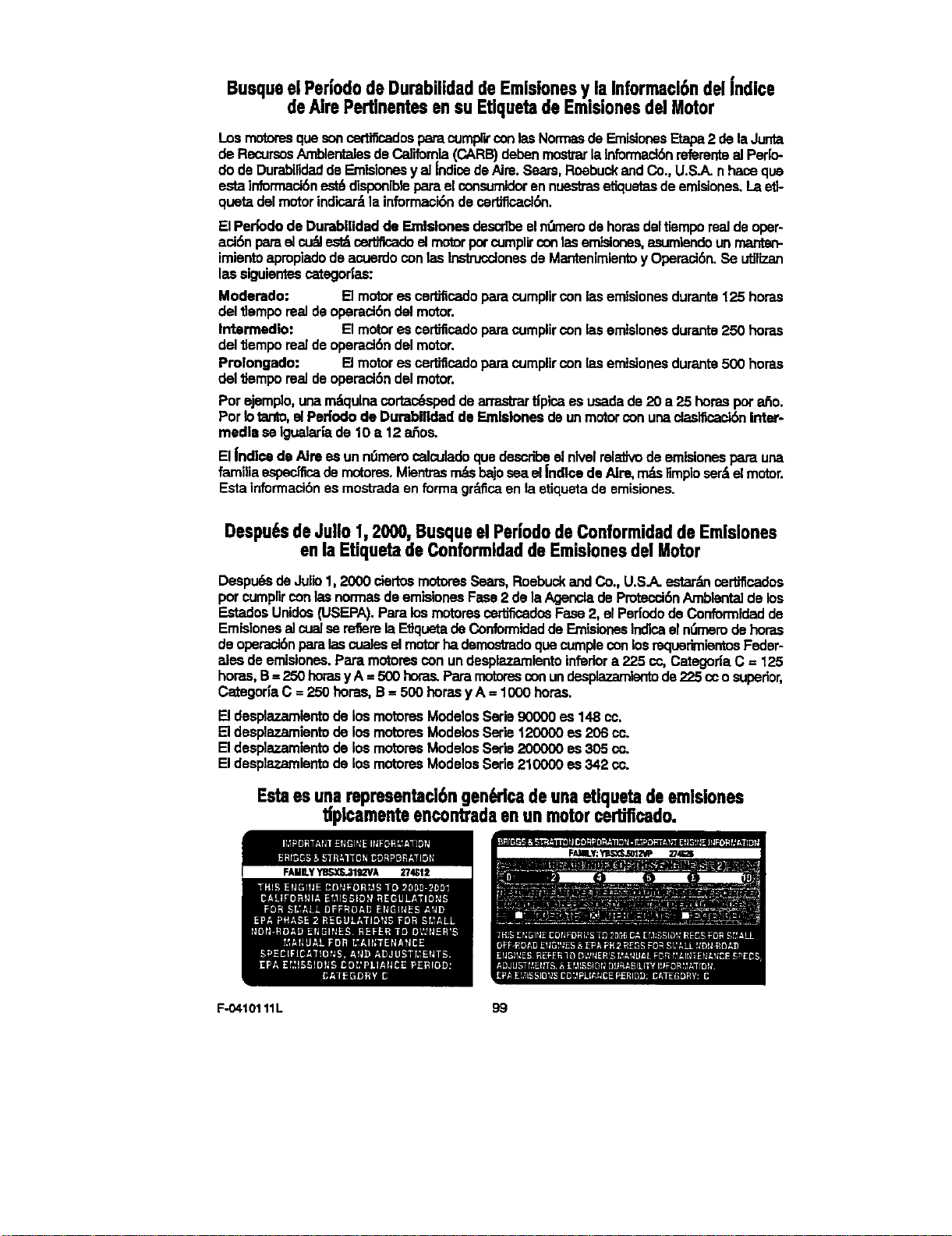
Busque el Periodode Durabilidad de Emisionesy.la Informacl6n del indice
de Aire Pertinentes en su Etiquetade Emmionesdel Motor
LosmotoresquasoncertificadoeparecumprrconlasNormasde EmisiooesEtapa2 delaJunta
deRecursosAmblentalesdeCalifornia(CARB)debenmostrarlainformaci6nmferentealPerlo-
dodeDurebilidaddeEmisionesyal IndicedeAire.Sears,RoebuckandCo.,U.S.A.nhacequa
estainformaci6nest6disponiblopareel consumidorennuestmsetiquetasdeemislooes.Laeft-
quetadalmotor indloa_lainformaci6nde oertffloack_n.
[] Per_odode Dumbilidad de Emlslonesdescribeelnt_merodehorasdeltiempoeel deoper-
aci6npareel cu#Jest_certJficadoel motorpotcumplh"conlasemisiooes,asumiendounmanten-
imientoapropiadodeacuerdoconlasInstrucotonesdeMantenimientoy Operaci6n.Se utiBzan
laselguientescategor|as:
Modemdo: [] motores cer'dficadoparecumplirconlasemisionesdurante125 bores
daltlemporeeldeoperaci6ndellmotor.
Intermedlo: [] motores oertificadoparacomplircon lasemlslonesdurante250 horas
dellJemporealdeoperaci6n delmotor.
Prolongado: [] motores cerSficadoparecumplircon lasemisionesdurante500 horas
delUemporeeldeoperacibndelmotor.
Porejemplo,unam_tqulnaco_d dearmskartipicaes usadede20 a 25 horaspota6o.
Porlotanto,elPeriododeDurabiUdadde Emlslonesdeunmotorconunadasificacl6nInter-
media seIgualeri'ade10 =,12 ahos.
ElJndloedeAim es unn_memcalculadoqua describeelnlvelmlafivodeemislonesparauna
farniliaespec[ficademotores.Mientrasn_s hajoseael JndlcedeAim, r_ limploser6elmotor.
Estainformaci6nesmostradaenformagr_.ficaenlaetiquetadeemisiones.
Despu6sde Julio 1,2000, Busque el Periodode Conformidadde Emlsiones
en la Etiquetade Conformidadde Emisiones del Motor
Despt.,_sde Jullo1,2000 ciertoemotoresSears,RoebuckandCo., U.S.A.estaganoertJficados
porcumplirconlasnormasdeemielonesFase2 deIsAgencladePmtecci6nAmbientaldelos
EstadosUnidos(USEPA).Para losmotoresoertlficadoeFees2, elPeriododeConformidadde
Emielonesel cualserefiemlaEtJquetadeConformidaddeEmisionesIndloael nt_rnemdebores
deoperaci6nparalascoalesal motorhademostradoquecumpleconlosrequerimientosFader-
alesde emisioees.Pare motorescon undesplazamientoinferiora 225 cc,CategorlaC= 125
horas,B= 250boresyA =500bores.Paremotoresconundesplazamlentode27_.5cco superior,
Categor|aC = 250 bores,B = 500 horasyA = 1000horas.
[] desplazamientode losmotoresModelosSerle90000 es 148 co.
[] desplazamientode losmotomsModelosSerie120000es 206 co.
[] desplazarnientode losmotoresModalosSerie200000 es 305 cc.
[] desplazamlontode losmotoresModelosSede210000 es 342 cc.
Estaesunarepmsentaci6ngen_'icadeunaetiquetadeemlsiones
tipicamenteencontradaenunmotorcerUflcado.
F-O410111L 99
Your Home
For repair - in your home - of all major brand appliances,
lawn and garden equipment, or heating and cooling systems,
no matter who made it, no matter who sold it!
For the replacement parts, accessories and
owner's manuals that you need to do-it-yourself.
For Sears professional installation of home appliances
and items like garage door openers and water heaters.
1-800-4-MY-HOME ® Anytime, dayornight
(1-800.469-4663) (U.S.A. and Canada)
W1NW.sears.com WW_N.SeEIrS .ca
OurHome
For repair of carry-in products like vacuums, lawn equipment,
and electronics, call or go on-line for the nearest
Sears Parts and Repair Center.
1-800-488-1222 Anytime,dayornight(U.S.A.only)
www.sears.com
To purchase a protection agreement (U.S.A.)
or maintenance agreement (Canada) on a product serviced by Sears:
1-800-827-6655 (u.s.A.)
1-800-361-6665 (Canada)
Para pedir servicio de reparacibn
a demicil'Do,y para ordenar piezas:
1.888-SU-HOGAR sa
SEAR,
Au Canada pour service en frangais:
1-800-LE-FOYER "c
(1-soo-s33-6_7)
W'_PN,ssars.ca
OSea_,RcebuckmdCo.
® Registered Trademark / TM Trademark I sMService Mark of Sears, Roebuck and Co.
® Mama Registrade / TM Marca de F_brlce I _ Mama de Servicio de Seam, Roebuc_kand Co.
acMarque de commerce I MoMarque d_posde de Sears, Roebuck and Co.


