PERFORMANCE
SAFETY;,ASSEMBLY, OPERATION AND MAINTENANCE.
Model
42566x89
Record The Following Information About Your Unit. This Information
Is Necessary When Ordering Parts Or In Case Of Loss Or Theft.
WHERE PURCHASED:
DATE PURCHASED: Month Day Year .
MODEL NO.: DATE OF MANUFACTURE:
-
BUILT IN THE
liSA
_710846
J

TABLE OF CONTENTS
WARRANTY ......................................... 2
RESPONSIBILITY OF THE OWNER .................... 3
SAFETY RULES ..................................... 3
ASSEMBLY .......................................... 9
PARTS BAG - CONTENTS ............................... 9
CHECK THE TIRES ...................................... 9
CHECK THE LEVEL OF THE MOWER HOUSING ............ 9
HOW TO INSTALL THE SEAT ............................. 10
HOW TO ASSEMBLE THE STEERING WHEEL .............. 10
HOW TO ASSEMBLE THE GAUGE WHEELS ............... 10
MAINTENANCE FREE BATFERY .......................... 11
HOW TO PREPARE THE ENGINE ......................... 11
IMPORTANT! BEFORE YOU START MOWING .............. 11
OPERATION ......................................... 12
LOCATION OF CONTROLS ............................... 12
ATTACHMENTS ......................................... 13
HOW TO USE THE THROTTLE CONTROL .................. 13
HOW TO USE THE BLADE ROTATION CONTROL ........... 13
HOW TO USE THE SPEED CONTROL PEDAL .............. 14
HOW TO DISCONNECT THE TRANSMISSION .............. 14
HOW TO SET THE PARKING BRAKE ...................... 15
HOW TO CHANGE THE CUTTING HEIGHT ................. 15
HOW TO STOP THE UNIT ................................ 15
HOW TO TRANSPORT THE UNIT .......................... 15
HOW TO OPERATE WITH THE MOWER HOUSING .......... 16
HOW TO OPERATE THE UNIT ON HILLS ................... 16
BEFORE STARTING THE ENGINE ......................... 17
HOW TO START THE ENGINE ............................ 17
OPERATING TIPS ....................................... 18
MOWING AND BAGGING TIPS ............................ 18
MAINTENANCE ...................................... 19
MAINTENANCE CHART .................................. 19
HOW TO CHECK THE MUFFLER .......................... 19
HOW TO REMOVE AND INSTALL THE BLADE .............. 2O
HOW TO SHARPEN THE BLADE .......................... 2o
HOW TO ADJUST THE BLADE ROTATION CONTROL ....... 21
HOW TO CHECK AND ADJUST THE DRIVE BRAKE ......... 23
HOW TO CHECK AND ADJUST THE CLUTCH .............. 23
HOW TO ADJUST THE SPEED CONTROL PEDAL ........... 24
MAINTENANCE FREE BATTERY .......................... 24
HOW TO CHARGE THE BATTERY ......................... 24
WHERE TO LUBRICATE ................................ 25
HOW TO CHECK THE FUEL FILTER ..................... 25
CHECK THE TIRES .................................... 25
HOW TO REMOVE THE MOWER HOUSING .............. 26
HOW TO INSTALL THE MOWER HOUSING ............... 26
HOW TO LEVEL THE MOWER HOUSING ................. 27
HOW TO REPLACE THE MOTION DRIVE BELT ............. 28
HOW TO REPLACE THE MOWER DRIVE BELT ............. 29
HOW TO REPLACE THE FUSE ............................ 30
HOW TO REPLACE THE LIGHT BULB ..................... 30
HOW TO CLEAN THE MOWER HOUSING .................. 30
STORAGE (OVER 30 DAYS) .............................. 30
TROUBLE SHOOTING CHART ........................ 31
SLOPE GUIDE ....................................... 32
DISTRIBUTOR LIST .................................. 33
REPAIR PARTS ...................................... 34
INDEX .............................................. 59
LAWN TRACTOR ACCESSORIES ...................... 60
....::::'!_< _;::::: ::::::::::::::_::::::::p :: :_:: :_:::::::::::::::::::::::::_:_::: :_. ::2;::_::::_::_:::_::: :_::::: ::::::::: ::::!:::::::_.:..::: ::: ::::::::.:::;::::::::_.::_q:: ::_:::::t:::::::::::::_:::::;:::: ::r: :.:::::::::::::::::::::::_:::;::::_::::::::t::::_:2::::;:;:;:::_;___:::t; :::_1::::_;_::_: _:: _::_:_:::::;:_t _t __ :_::L:_:._:__:_;_ _: :-:::£ _:_'_'_;._
.... YARDKING PERFORMANCE Two Year Limited Warranty
_r_ Yardking Performance warrants to the original purchaser that this unit shall be free from defects in material and workmanship
_!_::!1 under normal use and service for a period of Two (2) Years from the date of purchase: however, this warranty does not cover
H engines, accessories (such as snow blowers, snow blades, grass baggers and plows), transmissions, batteries and Normal
Ii_] Wear Parts (except as noted below) or transaxles as the companies tha! manufacture these items furnish their own warranties
l!_il and provide service through their authorized field service facilities For additional information, see the warranties covering these
_i}iJ particular parts. If you are uncertain whether your unit contains or is equipped with one or more of these parts, consult your dealer
H prior to purchase Subject to the terms and conditions noted in this Limited Warranty, we shall, at our option, repair or replace
_![!] at no cost to the original purchaser any part covered by this Limited Warranty during the applicable warranty period.
lil In the event the battery proves defective within ninety (90) days from the date of purchase, we will replace it without charge If
Ii!_:] the battery proves defective after (90)days but within one hundred twenty (!20)days from the date of purchase, we will replace
Hit for a charge of one half (1/2) of the retail price of the baltery in effect at the time of return.
I!_,_ Normal Wear Parts are defined as belts, blades, blade adapters, pneumatic tires, headlights and seat covers These parts ere
Iiil warranted to be free from defects in material and workmanship as delivered with the product Any claim for repair or replacement
_!il of Normal Wear Parts must be made within thirty (30) days of the date of purchase No claims involving damage caused from
_!} materia! use, abuse or misuse will be honored
H This Yardking Performance Two (2)Year Limited Warranty is your exclusive remedy; however, this warranty is void or does
_!il not apply to any unit that has been tampered with, altered, misused abused or used for rental or other commercial and/or
H professional (non-homeowner) uses Your warranty does not cover minor mechanical adjustments which are not due to any
f!iil defect in material or workmanship For assistance in making such adjustments, consult your Instruction Book
H To make a claim under this Yardking Performance Two (2) Year Limited Warranty, return the unit (or ifauthorized in advance,
H the defective part) alongwithyourproofofpurchasetoanAuthorized Service Center near you Toloc_tethenearestAuthorized
H Service Center, call the Central Parts Distributor for your area shown in the list provided with your unit or check the Yellow Page
_i1 listings in your local telephone directory if you return the entire unit we wi]l repair the unit If we authorize the return of the
_!_i_ defective part only, we will either replace or repair the part In the case of a defect in atransmission or differential (as distinguished
ilij from a transaxle), the entire transmission or differentia] must be returned since they do not include user serwceable parts
H This Yardking Performance Two (2) Year Limited Warranty gives you specific legal rights, and you may also have other rights
Iiilil which vary from state to state This Limited Warranty is given in lieu of all other expressed and implied warranties
Ii!I including the implied warranty of merchantability and warranty of fitness for a particular purpose. If you need additional
H information on this written warranty or assistance in obtaining service write or call: Yardking Performance. ©utdoor Power
_X Equipment, Customer Service Department, PO Box 268, Brentwood, Tennessee 37027. (1-800-289 8995)
710846 2

OWNER'S INFORMATION
This instructionbook isfor several different models. The instructions
are written fora person with some mechanical ability.Like mostser-
vice books,not allthe steps are described. Steps on howto loosenor
tightenfasteners ere steps anyone can followwithsome mechanical
ability. Read and followthese instructionsbefore you use the unit.
Knowyourproduct: Ifyou understandthe unitand howthe unitoper-
ates, you willgetthe best performance. As youread thismanual, com-
pare the illustrationstothe unit.Learn the locationand the function of
the controls.Tohelp preventan accident, followthe operating instruc-
tionsand thesafety rules. Keep thismanual forfuture reference.
IMPORTANT: Many units are not assembled and are sold in car-
tons. It isthe responsibility of the owner to make sure the assembly
instructionsinthis manual are exactly followed. Other unitsare pur-
chased in an assembled condition. On assembled units, itis the re-
sponsibility of the owner to make sure the unit is correctly
assembled. The owner must carefully check the unit according to
the instructionsin this manual before it is firstused.
RESPONSIBILITY OF THE OWNER
The responsibility ofthe owner is to follow the instructions below.
1. Carefully read and follow the rules for safe operation.
2. Follow ailthe assembly instructions.
3. Inspect the unit.
4. Make sure that the operator of the unitknows how to correctly
use all standard and accessory equipment.
5. Operate the unit only with guards, shields, and other safety
items in place and working correctly.
6. Correctly adjust the unit.
7. Service the unit only with authorized or approved replacement
parts,
8. Complete all maintenance on the unit.
Environmental Awareness
• Do not fill the engine's fuel tank completely full.
• Drain fuel for off-season storage.
• Use only unleaded gasoline.
• Service the air cleaner regularly.
• Change oilregularly. Use 30W oilin summer.
• Tune-up the engine regularly.
• Keep equipment in efficient operating condition.
• Dispose ofused engine oil properly.
SAFETY RULES
Safe Operation Practices for Riding Vehicles
As Recommended by American National Standards Institute
WARNING: This cutting machine is capable of amputating hands and feet and throwing objects. Failure to observe the
following safety instructions could result in serious injury or death to the operator or bystanders.
GENERAL OPERATION:
1. Read, understand and follow all instructionsin the Instruction Book, on the machine, theengine and with anyattachments before starting.
2. Only allow responsible adults familiar with the instructions to operate the machine.
3. Clear the area of objects such as rocks, toys, wire, etc. which could be picked up and thrown by the blade.
4. Be sure the area is clear of other people before mowing. Stop the machine if anyone enters the area,
5. Never carry passengers.
6. Disengage power to the mower or any attachments before backing up Do not mow in reverse unless absolutely necessary. Always
look down and behind before and while backing
7. Be aware of the direction the mower discharges. Do not point discharge from the mower at anyone or at places where people may be.
Do not operate the mower without either the entire grass bagger or the mower guard in place.
8. Slow down before turning
9 Never leave a machine unattended with the engine running. Always disengage the blade(s), set the parking brake, stop the engine and
remove the key before dismounting
10. Disengage power to attachment(s) when transporting or not in use Disengage the blade(s) when not mowing.
11. Stop the engine before removing the grass bagger or unclogging the chute
12. Mow only in daylight or good artificial light
13. Do not operate Ihe machine while under the influence of alcohol or drugs or when very tired.
14. Watch for traffic when operating near or crossing roadways.
15 Use extra caution when loading or unloading the machine when using a trailer or truck far transporting.
16. Disengage all attachment clutches before attempting to start the engine
17. Always wear safety glasses or an eye shield when you operate the unit to protect your eyes from foreign objects that can be thrown
from the unit. Always wear eye protection when you make an adjustment or repair to the machine.
! 8 Use care when pulling loads or using heavy equipment.
a. Use only approved drawbar hitch points.
b. Limit loads to those you can safely control.
c. Do not turn sharply. Use care when backing.
d. Use counterweights or wheel weights when suggested in the Instruction Book.
710846 3

OWNER'S INFORMATION
19. Do not operate this machine if you are taking drugs or other medication which can cause drowsiness or affect your ability to operate
this machine.
20. Do not use this machine if you are mentally or physically unable to operate this machine safely
SLOPE OPERATION:
Slopes and rough terrain are major factors related to loss of control and tip over accidents which can result in severe injury or
death. ALL slopes require extra caution. If you cannot back up the slope or if you feel uneasy on the slope, do not mow it. See the
"Slope Guide" in the back of this book to check for safe operation.
DO
1. Mow up and down slopes, not across.
2. Remove obstacles such as rocks, limbs, etc._
3. Watch for holes, ruts or bumps Uneven terrain could overturn the machine "Tall grass can hide obstacles"
4. Use slow speed on slopes. Do not make sudden speed changes.
5. Follow the manufacturer's recommendations for wheel weights or counterweights to improve stabiIity,
6. Use extra care with grass baggers or other attachments, they can change the stability of the machine.
7. Keep all movement on the slopes slow and gradual. Do not make sudden changes in speed or direction,
8. Avoid starting or stopping on a slope. Iftires lose traction, disengage the blades and proceed slowly straight down the slope.
DO NOT
!. Do not turn on slopes unless absolutely necessary, then only turn slowly and gradually downhill, if possible
2. Do not mow near drop-offs, ditches or embankments A wheel over the edge or an edge caving in could cause a sudden overturn and
an injury or death.
3. Do not mow on wet grass, Reduced traction could cause sliding.
4 Do not try to stabilize the machine by putting your foot on the ground
5. Do not use a grass bagger or other rear mounted accessories on steep slopes (greater than 10 degrees)
CHILDREN:
Tragic accidents can occur if the operator is not alert to the presence of children. Children are often attracted to the machine and
the mowing activity. NEVER assume that children will remain where you last saw them.
1 Keep children out of the mowing area and in the watchful care of an adult other than the operator
2. Be alert and t,u,rnthe engine off if children enter the area.
3. Before and when backing, look behind and down for small children.
4. Never carry children or any passengers. They may fall off and be seriously injured or interfere with the safe operation of the machine
5 Never allow children to operate the machine. Instruct children in the dangers of the machine
6. Use extra care when approaching blind corners, shrubs, trees or other objects that may obscure vlspon
SERVICE:
1 Use extra care when handling gasoline and other fuels, Fuels are flammable and the vapors are explosive.
a. Use only an approved container.
b. Never remove the gas cap or add fuel with the engine running, Allow the engine to cool for several minutes before refueling. Do
not smoke.
c Never refuel the machine indoors.
d. Never store the machine with fuel in the tank or fuel container inside where there is an open flame, such as a water heater
2. Never start or run the engine inside a closed area
3. Keep all nuts and bolts, especially the blade attachment nuts tight. Frequently check the blade(s) for wear or damage such as cracks
and nicks A blade that is bent or damaged must be immediately replaced with an original equipment btade from an authorized service
dealer For safety, replace the blade every two years Keep the equipment in good condition
4. Never tamper with the safety devices Check their proper operation regularly
5. To reduce fire hazards keep the machine free of grass, leaves or other debris build up Oean up oil or fuel spills Allow the machine
to cool before storing.
6 Stop and inspect the equipment if you strike an obiect Repair, if necessary before restarting
7 Never make adjustments or repairs with the engine running The carburetor can be adjusted with theeng_nerunnlng Do not change
the engine governor settings or over-speed the engine.
8 Grass bagger components are subject to wear. damage and deterioration which could expose moving parts or allow ob}ects to be
thrown For storage, always make sure the grass bag is empty. Frequently check components and replace with manufacturer's recorn
mended parts when necessary.
9 Mower blade(s) are sharp and can cut, Wrap the blade{s) or wear gloves and use extra cauhon when servicing them or the blade housing
8re_
10 ©heck the brake operation frequently Adjust and service as required
1t. Wait for all movement to stop before servicing any part of the unit
i_ Look for this symbol to indicate important safety
precautions. This symbol indicates: "Attention!
Become Alert! Your Safety Is At Risk."
710848

Each person that operates power
equipment must learn to use correct and
safe mowing procedures. To help you
learn, carefully read the following
pages. Most of the time the operator was
not correctly shown or did not read the
instructions on the unit or in the instruction
Book before using the unit. Also, some
operators do not have enough experience.
The result is unsafe use, endangering the
operator, bystanders and the equipment.
Another result can be a poor appearance
of the area mowed.
Read this book. Read the instructions on
the unit. Operate the mower according to
the Safe Mowing Guide. Follow all safety
rules, cautions or warnings in this book
and on the unit. Make sure anyone that
uses the unit reads the instructions and is
told how to safely operate the mower.
The mower will give you good service and
durability, if operated in normal conditions.
If the mower is not correctly serviced or is
used where the terrain is rough or
unsuitable, product performance and
safety will be decreased.
Correct clothing is an important part of safe
mowing. Safety glasses will protect the
eyes from objects discharged by the
mower. Safety shoes with steel plates can
protect a foot from injury by the blade, For
protection from objects discharged from
the mower, wear clothing that will cover the
arms and legs.
Before you start cutting the grass, practice
using the mower in a large open and level
area. Learn the location of the controls on
the mower Know the purpose of the
710846
SAFE MOWING GUIDE
controls and how they work. In an
emergency, how fast you can stop the
blade is important. Learn how to control
the mower at all times.
Many engines are started by hand. When
you use a pull start or rope start, place
your feet apart and away from the blade(s).
Hold the rope handle tight. Never wrap the
rope around your arm or fingers for a
=better grip". To start the engine, follow the
instructions on the mower, in this book and
in the engine operating instructions.
For electric start engines, sit in the seat to
start the engine. The battery can be
dangerous. Follow the instructions on the
battery, the acid container, and in this book
when working with the battery. Even small
batteries have enough voltage to cause an
injury.Always be careful.
The mower is designed to be operated by
one person. Never let another person ride
with you on the unit or on any accessories.
A passenger will make the unit harder to
control, block the visibility or distract the
operator and is dangerous to the operator,
the passenger and the equipment. Without
a passenger seat, the passenger can fall
from the mower or contact dangerous
parts A mower is not a toy for showing off
or for giving rides.
Never cut a wet lawn Wet grass can
cause an accident, affect mower
performance and can cause problems with
future lawn growth and appearance Wet
grass is slippery and can cause the mower
to slip Someone can get iniured by
touching the blade(s). Wet grass tends to
clog the mower, causing poor discharge.
Cut wet grass will collect on the lawn,
retarding the growth of the grass Also.
getting the mower wet will cause parts to
rust and decrease the life of the unit
When you took over the lawn, remember
obstacles that cannot be removed, like
pipes, stumps or rocks Keep away from
these obstacles that can cause damage to
the mower or injury to the operator or a
person near the mower. Clear the area of
rocks, toys, wire or other loose objects
These items can damage the mower or
can be discharged by the mower blade
5
The blade of a power mower rotates very
fast. It can discharge rocks and other
objects over a long distance which can be
dangerous. The force of the objects can
break windows, cause injuries or even put
an eye out. Most of the time the injury is to
a person, like a child. Keep every person
completely away from the area to be
mowed, Make sure the grass is not
discharged toward anyone. Planning your
mowing pattern has a double advantage. It
can decrease the possibility of an injury
and make the clean up after mowing
easier.
Check the terrain of the area to be mowed.
Mow in a pattern that will keep you away
from dangerous areas Check the distance
you need to stop and the distance
available to turn Slopes and rough terrain
must be mowed carefully and some areas
must not be mowed at al!. With riding
mowers, mow up and clown the hill When
you must mow rough terrain or on slopes,
drive slowly and stop in these areas only in
an emergency. Before you ride up or down
a slope, try to back straight up the slope.
Do not ride up or down a slope that is too
steep to back straight up. See the "Guide"
in the back of this Instruction Book to
check anyslopes
Before you start cutting, make sure the
mower was completely assembled
according to the Instruction Boor, If the
mower was completely assembled at the

store, you must still check the mower
according to the assembly instructions.
Make sure the mower is correctly
assembled and that all fasteners are tight.
Make sure the engine has the correct
amount of oi1.Check these items often
during the lifeof the mower.
Your mower has a gasoline engine.
Gasoline is a dangerous fuel. Keep
gasoline only in an approved safety
gasoline container. Do not keep large
amounts of gasoline. When you add
gasoline to the fuel tank, do not smoke.
Store the gasoline container and the
mower in an area that has good ventilation.
Also, keep the gasoline away from any
flames like the pilot light of a furnace or
any other source of ignition. If the mower is
to be stored for more than a few weeks,
remove the gasoline from the fuel tank.
When inside an enclosure, do not add
gasoline to the fuel tank. Before you add
gasoline, move the mower outside and add
gasoline carefully. Before you start the
engine, remove any gasoline from the
outside of the fuel tank or from the mower,
Warm gasoline will expand. Leave some
space in the fuel tank for the gasoline to
expand. Also, the fuel cap has a vent hole
for fuel vapors. Always use the correct fuel
cap. Failure to follow safety rules about
gasoline will cause fires and explosions,
injury to you and dk_mage to the equipment
and other property.
,,,, k_,. _t.. ib
, iir
If you add gasoline to an engine that is
running or hot, the result can be an
explosion, Before you add gasoline, stop
lhe engine and let the engine cool for
several seconds. Remove dry grass and
other debris from the mower Keep the
mower clean to improve the performance
help the engine and transmrsslon run
cooler, extend the life of moving parts, and
decrease the danger of a fire
Fires and explosions are not the only
dangers when working around a mower
The engine, transmission, and the muffler
will get hot in several minutes when the
engine is running. Do not touch these parts
of the mower. Stop the engine Let the
710846
SAFE MOWING GUIDE
engine and transmission cool before
servicing the mower. Remember, exhaust
fumes are dangerous. Never operate the
engine inside a building.
When you get a new mower, il can be a
new experience for the family. Tell each
person how a mower can be dangerous.
Remember, a mower is not a toy A mower
is not to be used by children or anyone not
old enough, strong enough or that does not
have experience.
Ifthe mower is not correctly assembled.
not operaled correctly, or not regularly
serviced, the mower can be dangerous.
The most important rule to follow is always
use good judgement and common sense.
Mow safely and carefully.
Your mower will easily cut thick grass
Fingers, feet and other parts can also be
cut by the blade Injuries occur when the
operator does nol think and reaches into
the chute opening. Always operate the
mower as if the blade is rotating. Do not
service or make an adjustment, except to
the carburetor, while the engine ts running
When you mow, remember thai children
are attracted to the mower. Always use
caution when mowing around obstacles
like trees or shrubs or when moving
backward Only mow in a forward direction
if possible. Your visibility is decreased
when you mow backward. Also, the blades
are made to cut while the unit is moving
forward. If you mow backward, the cutting
performance decreases.
Before you leave the mower, stop the
engine Remove the key. Disengage and
lower any attachment Set the parking
brake. Never mount or dismount from the
seat while the engine is running. An
accident can occur if you touch the brake.
speed control pedal, throttle, or blade
control while the engine is running. Mount
and dismount from the seat on the side of
the unit that is marked ENTER-EXIT
Use only accessories that are factory
approved for your mower The wrong
accessory can decrease the safety of the
mower and can even damage the uRi_
Read and follow the instructions ncluded
with the accessory and the mower
Use only original equlpmen_ or
replacement parts that are factory
approved for service If you need service
select an Authonzed Service Center for
your mower If you do the work on the unit.
follow the instructions in the Instruction
Book
j J =- <
Make sure you are in good condition when
you mow When you mow for several hours
your reflexes will decrease and your mind
will not be as alert Take a short break or
an accident can occur If the temperaturels
hot use caution to prevent dehydration If
you are tired angry or not completely alert
do not operate the mower If you use
alcohr, I medication or drugs, do not use
the Inower or any type of power
equipment
Engine speed is a key to safe mowing and
to a good looking lawn The maximum
speed of the engine was set at the factory
Do not change the setting of the engine
governor
Selecl the maximum engine and ground
speed that is right for the terrain and the
height of the grass The blade cuts best
when the engine is operating at maximum
speed The engine and transmission will
also run cooler at maximum engine speed

SAFE MOWING GUIDE
Also, the grass bagger willfunction better
when the engine is operating at maximum
speed. On slopes, decrease the ground
speed and use care making sure the
mower feels safe to operate.
If the weather conditions are bad, do not
mow. If weather conditions become bad,
stop cutting and finish later. It is dangerous
to cut grass in the rain. Always find
protection in an electrical storm. Ifthe
weather conditions are extra dry, protect
your eyes with safety glasses from the dust
and from the objects discharged by the
mower. Also, a dust or a pollen mask can
help.
Your mower is equipped with a number of
safety devices which are important to the
safety of the operator and bystanders and
must never be changed or removed from
the mower. Ifa safety device is lost,
damaged or no longer functions, repair or
replace the device before you operate the
mower.
Itis best to mow during the day. If you
must mow at night, make sure there is
enough light for safe operation.
Your mower will require regular
maintenance and service. The
maintenance schedule depends on the
hours of use. Also, mowing conditions can
change the schedule. Check the
Instruction Book for more information.
Correct maintenance will help the mower
function safely.
Do not service the
mower (except for the
carburetor adjustment)
while the engine is |_[_11t .zl
running. Before you |_
service the unit, even _'_
with the engine stopped,lP _"
always disconnect the
wire from the spark plug
to prevent the engine
from starting
If you hit a large object during operation,
stop the engine Remove the wire from the
spark plug. Carefully inspect the mower for
damage Before you start the engine
again, make the necessary repairs tf you
feel new or excessive vibration.
immediately stop the engine and check for
the problem. Vibration can be a warning of
a problem. Keep all nuts, bolts and screws
tight.
The blade is the most dangerous part of
the mower. Frequently check the blade and
the blade mounting fasteners. Keep the
fasteners tight. If the blade hits a solid
object, stop the engine. Remove the wire
from the spark plug. Check for a blade that
is bent, cracked or for other damages.
Before you start the engine, replace a
damaged blade(s). For safety, replace the
blade every two years.
A sharp blade decreases the workload on
the engine and more evenly cuts grass
Frequently sharpen the blade for a better
looking cut. Use the left side of the mower
housing to trim near an object.
A grass bagger is a good accessory for
your mower. For best performance and
safety, make sure the grass bagger is
approved for use with your mower. Follow
the assembly and operation instructions
included with the grass bagger.
Some grass baggers require e special
blade for best performance. Before you
attach, check, or empty the grass bagger,
always stop the engine Before each use of
the grass bagger, check for cracks, wear or
deterioration. Before you use the grass
bagger, replace a damaged part with a
replacement part approved by the factory.
For you to have a good green lawn, follow
the mowing procedures below, Do not cut
the grass too short If you cut the grass too
short you can cause the grass to become
yellow or make the lawn look brown. Use a
lower height of cut in cool months when
the grass is thicker Raise the height of cut
in hot dry periods If you cut the grass with
a blade that is not sharp or at a slow
engine speed you can damage the grass.
Move the throttle control to the FAST
position when mowing and using the grass
bagger. Also, use a slower ground speed
when using the grass bagger,
Ifyou change the direction or pattern ofcut
slightly every time you mow will make the
grass grow stronger and thicker. Do not
add oilor gasoline to the mower while on
the lawn. Spilled oil or gasoline can killthe
grass. In high or thick grass, do not try to
cut all the grass the firsttime. Raise the
height of cut on the first cutting and lower
the height for the next cutting. Another way
isto cut only part of the width ofthe mower
and decrease your ground speed (not the
engine) to move more slowly so that the
mower can discharge the grass as it
moves forward.
Understand the controls and how they
work Learn the ground speed(s) of your
mower Check the stopping distance
required at different travel speeds. Check
the turning radius of the mower. The
controls on your riding mower are different
from an automobile. The throttle is
operated by hand and holds the engine
speed constant until it is changed. The
location of the travel speed control is
different from that of an automobile. Also,
the brake and clutch systems are different.
Remember the procedures to follow in an
emergency. Remember, turning off the
engine ignition switch will stop the blade
and the drive mechanism. If the traction of
the wheels is lost or does not feel safe,
disengage all systems and stop the
engine Dismount from the mower. Push
the unit to a safe place before you begin
mowing again.
Your unit has an electrical system that
includes an operator presence switch in
the seat. The operator presence switch
detects if the operator is sitting on the seat.
The engine will stop if the operator leaves
the seat when the blade engagement
control is engaged, This operator presence
switch is a safety device only. It must nol
regularly be used to stop the engine or the
blade There are other control systems on
the mower for this purpose. Always keep
the operator presence switch and other
safety devices and controls in place and
operating for your protection.
Remember, your mower is a tool.that can
be dangerous if it is not correctly used.
Follow the instructions in this Instruction
Book Safe and careful use of the mower
will give you many safe hours of problem
free use.
710846 7
STEPS TO FOLLOW
BEFORE MOWING
• Be sure to dress correctly. Wear hard shoes, not sandals or tennis shoes.
• Examine the blade. A blade that is bent, cracked, or damaged must be replaced with a factory replacement blade
• Fill the fuel tank outside. Clean off spilled fuel.
• Read and follow the Owner's Manual. the instructions with the engine, and the instructions with any attachments. Owner's Manual
instructions are for your safety and the safety of others
• Exhaust fumes are dangerous Start the engine outside.
• Make sure all safety devices are in place and working correctly.
• Operation of the mower is only for a person that has experience
• Wet grass can be dangerous. Let the grass dry
• instruct children and others to keep away from the work area
• Never cut the grass without good light
• Pick up loose obiects. Remove them from the mowing area
WHILE MOWING
• Watch for fixed objects and avoid them They can damage the mower or cause iniury
• A hot engine, muffler, and transmission will cause a burn Do not touch
• Inclines and slopes must be carefully mowed See the "Guide" in the back of this book to check a slope.
• Lack of daylight or good artificial light is cause to stop mowing
• Examine the mower, the blade, and other parts for damage after hLtting a foreign obiect or if the unit vibrates excessively.
• Do not make adjustments or repairs without stopping the engine Disconnect the spark plug wire.
• On or near roa_s, watch out for traffic Direct discharge away from roads
• When mowing, avoid areas where traction is unsure Look back before changing direction of travel
• In heavy grass, raise the cutting height Cut slower Stop the engine to remove clogged grass from the mower
• Never remove any safety related parts
• Do not pour gasoline into a engine that is hot or running
AFTER MOWING
• Always let the mower cool before storing in an enclosed area
• Foreign material on the mower is dangerous. Clean off grass, leaves, grease and oil before storing
• Tighten all loose nuts. bo_ts and screws before you use the unit
• Empty and clean any grass catcher or other accessory
• Remove the key or disconnect the spark plug wire to prevent unauthorized use
• Make sure the mower is not kept near a source of ignition. Gas fumes can cause an explosion
• Only original parts or factory approved substitutes can be used to service the mower
• When storing the mower for an extended period, remove the fuel from the fuet tank
• Instruct children to leave the mower alone It is not a toy
• Never keep gasoline near a source of ignition Always use an approved container Keep gasoline away from children
• Lubricate according to the tnstruction Bcok See 'Lubrication"
IMPORTANT--Read the Instruction Book. Keep this book for future use and reference.
WARNING: Look for this symbol to point out important
safety precautions. It means: "Attention! Become Alert!
Your Safety Is Involved."
710848 8

ASSEMBLY
ASSEMBLY
This instructionbook is forseveral models. Some parts oraccesso-
ries are not included on all models. Read and follow the assembly
and adjustment instructions foryour mower. All fasteners are inthe
parts bag. Do not discard any parts or material until the unit is
assembled.
_lb WARNING: Before doing any assembly or mainte-
nance to the mower, remove the wire from the spark
plug.
NOTE: In this instruction book, left and right describe the loca-
tion of a part with the operator on the seat.
PARTS BAG - CONTENTS
The fasteners and other loose parts are shown below. The fasteners are shown full size. The quantity is shown in brackets ().
71(_226
(2) CarriageBolt
94160
(2) Knob
71(_25
(2) Wing Nut
©
71(_257
(2) Washer
O 71011_ 9
710930 (6) Washer
(2) Locking Ring
327350
CHECK THE TIRES
Check the air pressure in the tires. Tires with too much air pressure
will cause the unit to ride rough. Atso. the wrong air pressure will
keep the mower housing from cutting level. The correct air pressure
(PSI) is 14 PSi (1 BAR). The tires were over inflated for shipment
CHECK THE LEVEL OF THE MOWER HOUSING
Make sure the level of cut is still correct. After you mow a short
distance, look at the area that was cut. If the mower housing does
not cut level, see the instructions on "How To Level The Mower
Housing" in the Maintenance section of this instruction book.
710846 9

ASSEMBLY
HOW TO INSTALL THE SEAT
Use the fasteners shown below toinstall the seat. The fasteners are
shown at fug size.
3.
Check the operating position of the seat. If the seat needs to
be adjusted, loosen the two wing bolts. Slide the seat forward
orbackward along the seat adjusting holes as shown. Tighten
the wing bolts (A).
1.
2
(A)
94160
(B)
710257
Carefully remove the plastic beg from the seat.
Align the holes in the seat hinge to the holes in the seat
(Figure 1). Fasten the seat to the seat hinge with the fasteners
as shown.
Seat
Seat Hinge
Seat
Adjusting Hole
A
ure t
HOW TO ASSEMBLE THE STEERING WHEEL
Fasteners are not required to assemble the steering wheel. Attach
the steering wheekas follows:
1. Make sure the front wheels point forward.
2. Look at the hub of the steering wheel. Make sure the locking
clip is in place inside the hub.
3. Slide the cover over the steering post (Figure 2)
4. Slide the steering wheel onto the steering post. Push on the
steering wheal. The steering wheel will lock onto the steering
post. Pull on the steering wheel Make sure the steering wheel
is locked in place.
5 Some models have an optional decal in the parts bag Attach
the decal to the center of the steering wheel as shown.
Steeling Wheel
Steering Post
Hub
Cover
(Optional)
HOW TO ASSEMBLE THE GAUGE WHEELS
Use the fasteners shown below to install the gauge wheels. The
fasteners are shown at full size.
1 Attach the gauge wheels to the axle bolts with the fasteners.
Locking
Ring
Axle Bolt
Was her_
Gauge Wheel
Figure 3
NOTE: The axle bolt is mounted in the LOW position. To change
the position to a higher cutting position, see "How To Adjust
The Gauge Wheels" in the Maintenance section.
7t 0846 10
ASSEMBLY
MAINTENANCE FREE BATTERY HOWTO CHARGETHE MAINTENANCEFREE BATTERY
IMPORTANT: Before you attach the battery cables to the
battery, check the battery date. The battery date tells If the
battery must be charged.
1. Check the battery date on top of the battery (Figure 4).
2. If the battery is put into service before the battery date, the
battery cabJes can be attached without charging the bsllery.
See "How To install The Battery Cables".
3. If the battery is put into service after the battery date, the
battery must be charged. See "How To Charge The
Maintenance Free Battery".
1.
2.
4.
WARNING: When you charge the battery, do not
smoke. Keep the battery away from any sparks. The
fumes from the battery acid can cause an explosion.
Remove the battery and battery tray.
Remove the protective caps from the battery terminals
Use a 12 volt battery charger tocharge the battery Charge at
a rate of 6 amperes for one hour. If you do not have a battery
charger, have an authorized service center charge the battery.
Installthe battery and battery tray. Make sure the positive (+)
terminal is on the left side
HOW TO INSTALL THE BATTERY CABLES
i_ill WARNING: To prevent sparks, fasten the red cable to
the positive (+) terminal before you connect the black
cable.
Use the fasteners shown below to install the battery cables. The
fasteners are shown at full size
(A) (B)
710226 710225
1 Remove the protective caps from the battery terminals.
2 Fasten the red cable to the positive (+) terminal with the fas-
teners as shown (Figure 4).
3.
Fasten the black cable tothe negative (-} terminat withthe fas-
teners as shown.
I
Batte_ P_itive (+)
Date Code Terminal
B
\
A
/
HOW TO PREPARE THE ENGINE
NOTE: The engine was shipped from the factory filled with oil.
Check the level of the oil. Add oil as needed.
See the engine manufacturer's instructions for the type of gasoline
and oil to use Before you use the unit, read the information on
safety, operation, maintenance, and storage
WARNING: Follow the engine manufacturer's
instructions for the type of gasoline and oil to use.
Always use a safety gasoline container. Do not
smoke when adding gasoline to the engine. When
inside an enclosure, do not fill with gasoline. Before
you add gasoline, stop the engine. Let the engine
cool for several minutes.
IMPORTANT: This unit is equipped with an internal combustion
engine and must not be used on or near any unimproved
forest-covered, brush-covered or grass-covered land unless
the engine's exhaust system is equipped with a spark attester
meeting applicable local or state laws (if any). If a spark
arrester is used, it must be maintained in effective working
order by the operator.
In the State of California the above is required by law (Section
4442 of the California Public Resources Code). Other states
may have similar laws. Federal laws apply on federal lands.
See an Authorized Service Center for a spark arrester for the
muffler.
In some areas, local law requires the use of a resistor spark
plug to control the ignition signals. See an Authorized Service
Center for a resistor spark plug for the engine.
IMPORTANT! BEFORE YOU START MOWING
J Check the engine off.
_1 Fill the fuel tank with gasoline.
Check the level of the mower housing.
710846
_1 Check the air pressure of the tires.
_1 Attach the battery cables.
11

OPERATION
Throttle Control
Lever
Blade Rotation
Control
Brake Pedal
Speed Control
Pedal
Lever
LOCATION OF CONTROLS
BLADE ROTATION CONTROL: Usethebladerotation
control to start and stop the rotation of the hi,de
BRAKE PEDAL: Use the brake pedal to qu!ckly stop
HEADLIGHT SWITCH: The headlight switch is the first part
of the ignition switch. To use the lights with the engine running, turn
the key to the position for the lights
IG NITIO N SWITCH: use the ignition switch to start and stop
the engine
BATTERY LIGHT: Indicates whether battery is being re
charged when engine is running When the engine is running and
the light is on this means the battery IS charging, tf indicator _snot
on, have a battery and/or engine charging wtem checked by an
authorized service dealer.
710846
12
OK LIGHT: If this indicalor light is on. the engine will not start
1 Your clutch-brake pedal may not be fully depressed.
2 The blade rotation contro! may not be in the DISENGAGE posi-
tion
AUTOMATIC DRIVE DISCONNECT: usethe aulo-
matic drive disconnect located under the seat to disengage the
transmission.
LIFT LEVER: Use the lift lever to change the height of cut
PARKING BRAKE LEVER: use the parking brake lever
to engage the brake when you leave the unit
SPEED CONTROL PEDAL: use thespeed contro!pedal
to change the speed and the direction of the unit
THROTTLE CONTROL LEVER: Usethethrottlecontrol
lever to tncrease or decrease the speed of the engine

OPERATION
ATTACHMENTS HOW TOUSETHE BLADEROTATIONCONTROL
This unitcan use many different attachments. See the attachment
page in this book. This unit can pull attachments like a lawn
sweeper, a lawn aerator, or a hopper spreader. This unitcan notuse
attachments that engage the ground like a plow, a disk harrow, or
a cultivator.
HOW TO USE THE THROTTLE CONTROL
Use the throttle control to increase or decrease the speed of the
engine.
CAUTION: Always operate the engine with the throttle control
in the FAST position. If the engine runs for several minutes at
slower than the FAST position, the engine and transmission
will overheat and can be damaged.
The FAST position is marked with a detent. For normal opera-
tion and when using a grass bagger, move the throttle control
to the FAST position. For maximum charging of the battery and
for a cooler running engine and transmission, operate the en-
gine in the FAST position,
2. For transport and to tow pull behind attachments, control the
ground speed with the speed control pedal•
3. The engine governor is set at the factory for maximum perform-
ance. Do not adjust the governor to increase the speed of the
engine.
The blade rotation control is next to the steering wheel (Figure 6).
Use the blade rotation control to engage the blade(s) or tooperate
a snow thrower attachment•
1. Before you startthe engine, make sure the blade rotation con-
trol is in the DISENGAGE position•
2.
3.
Move the blade rotation control tothe ENGAGE position to
rotate the blade(s).
Note: If the engine stops when you engage the blade(a),
the seat switch is not activated. Make sure you sit in the
middle of the seat. Also, make sure the wire is connected
to the seat switch.
Move the blade rotation control to the DISENGAGE position
to stop the blade(s). Before you leave the operator's position,
make sure the blade(s) has stopped rotating.
4. Before you ridethe unit across a sidewalk or a road, move the
blade rotation control to the DISENGAGE position.
_lb WARNING: Always keep your hands and feet away
from the blade, deflector opening, and the mower
housing when the engine runs.
D_engage
Position
Blade Rotation Control
Engage Position
Figure 6
710846 13
OPERATION
HOW TO USE THE SPEED CONTROL PEDAL
The drive system uses a Hydrostatic Automatic Drive transmission.
The Hydrostatic transmission is very easy to operate. This type of
drive system does not require a shift lever or a clutch pedal.
The speed and direction of travel is controlled by a singte speed
control pedal operated with your rightfoot. Do notuse the teftbrake
pedal in normal operation. Only use the left brake pedal to quickly
stop in an emergency.
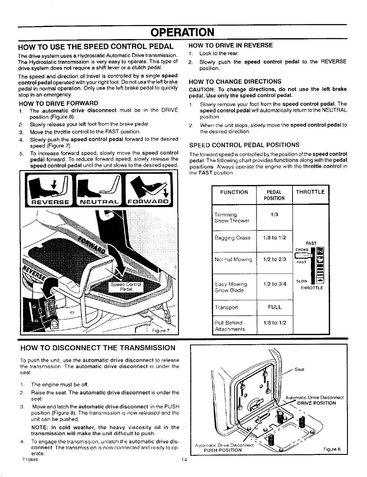
HOW TO DRIVE FORWARD
1. The automatic drive disconnect must be in the DRIVE
position (Figure 8).
2. Slowly release your left foot from the brake pedal
3. Move the throttle control to the FAST position.
4. Slowly push the speed control pedal forward to the desired
speed (Figure 7).
5. To increase forward speed, slowly move the speed control
pedal forward. To reduce forward speed, slowly release the
speed control pedal until the unit slows to the desired speed
Figure 7
HOW TO DRIVE IN REVERSE
1. Look to the rear.
2. Slowly push the speed control pedal to the REVERSE
position.
HOW TO CHANGE DIRECTIONS
CAUTION: To change directions, do not use the left brake
pedal. Use only the speed control pedal.
1 Slowly remove your foot from the speed control pedal. The
speed control pedal w!tlautomatically return tothe NEUTRAL
position.
2. When the unit stops, slowly move the speed control pedal to
the desired direction.
SPEED CONTROL PEDAL POSITIONS
The forward speed iscontrolled by the position of the speed control
pedal The following chart provides functions along with the pedal
positions Always operate the engine with the throttle control in
the FAST position
FUNCTION
Trimming
Snow Thrower
PEDAL
POSITION
1/3
1/3 to 1/2
1/2 to 2/3
Bagging Grass
Normal Mowing
Easy Mowing 1/2 to 3/4
Snow Blade
Transport FULL
1/3 to 1/2Pull Behind
Attachments
THROTTLE
FAST
FAST
lib
D
m
SLOW _
THROTTLE
HOW TO DISCONNECT THE TRANSMISSION
To push the unit, use the automatic drive disconnect to release
the transmission The automatic drive disconnect is under the
seat.
1. The engine must be off.
2. Raise the seat. The automatic drive disconnect is under Ihe
seat.
3. Move and latch the automatic drive disconnect in the PUSH
position (Figure 8). The transmission is now released and the
unit can be pushed.
NOTE: In cold weather, the heavy viscosity oil in the
transmission will make the unit difficult to push.
4 To engage the transmission, unlatch the automatic drive dis-
connect The transmission is now conl_ected and re_dy tOop-
erate
710846 14
sea,
A ut°rp_uatsH Drt(_; ITDli_)CN°nnec` _'_ -_--_--/_ F,gure 8

OPERATION
HOW TO SET THE PARKING BRAKE
1. Completely push the brake pedal forward.
2. Lift the parking brake lever (Figure 9).
3. Remove your foot from the brake pedal and then release the
parking brake lever. Make sure the parking brake will hold the
unit.
4. Torelease the parking brake, completely push the brake pedal
forward. The parking brake will automatically release.
WARNING: Before you leave the operator's position,
,_ move the shift lever to the neutral (N) position. Set the
parking brake. Move the blade rotation control to the
DISENGAGE position. Stop the engine arid remove
the ignition key.
HOW TO CHANGE THE CUTTING HEIGHT
To change the cutting height, raise or lower the lift lever as follows.
1 Move the lift lever forward to lower the mower housing and
back to raise the mower housing (Figure 10)
2 When you ride on a sidewalk or road, move the lift lever to the
highest position and move the blade rotation control to the
DISENGAGE position.
UftLever
HOW TO STOP THE UNIT
1 Slowly remove your foot from the speed control pedal. The
speed control pedal will automatically return to the NEUTRAL
position and the unit will stop
2. Move the blade rotation control to the DISENGAGE position.
3 Set the parking brake.
,_ WARNING: Make sure the parking brake will hold the
unit.
4. Move the throttle control to the SLOW position.
5 To stop the engine, turn the ignition key to the OFF position
Remove the key.
HOW TO TRANSPORT THE UNIT
To transport the unit, follow the steps below
1 Move the blade rotation control to the DISENGAGE position
2 Raise the lift lever to the highest position
3. Move the throttle control to the FAST position.
4. Slowly push the speed control pedal forward to the desired
speed
710846 15
OPERATION
HOW TOOPERATEWITH THE MOWER HOUSING
1,
2
3,
WARNING: The deflector is a safety device. Do not re- 4.
move the deflector. The deflector forces the dis-
charged material toward the ground. Always keep the 5.
deflector in the down position. If the deflector is dam- 6,
aged, replace the deflector with an original equipment
part from an authorized service center. 7.
Start the engine.
Release the parking brake.
Move the lift lever to s height of cut position, in high or thick
grass, cut the grass in the highest position first and then lower
the mower housing to a lower position.
CAUTION: Do not operate with the mower housing in the
LEVEL ADJUSTMENT position, If you operate in the
LEVEL ADJUSTMENT position, the mower housing and
blades can be damaged.
8,
Move the throttlecontrotto the SLOW position.
Move the blade rotationcontrol to the ENGAGE position.
Move the throttle control Io the FAST position.
Slowly push the speed control pedal to the desired speed.
NOTE: When you mow in heavy grass or mow with a grass
bagger, use a slow forward speed.
Make sure the level of cut set at the factory is stillcorrect. After
you mow a short distance, look at the area that was cut. If the
mower housing does not cut level, see the instructions on "How
To Level The Mower Housing" in the Maintenance section,
,_ WARNING: For better control of the unit, always
select a safe speed.
HOW TO OPERATE THE UNIT ON HILLS
WARNINg! Do not ride up or down slopes that are too 2.
steep to back straight up. Never ride the unit across
a slope. See the "Slope Guide" in the back of this 3
book for information on how to check slopes.
HOW TO OPERATE ON A HILL
1 Control the speed only with the speed control peda! Do not use
the brake pedal on a hill.
2, To help prevent an accident, slowly move the speed control
pedal. Avoid sudden turns or changes in speed
3. To reduce forward speed when going down a hill, slowly release
the speed control pedal until the unit slows to the desired
speed.
HOW TO STOP ON A HILL
1. Avoid stopping on a hill. If you must quicMy stop tn an emergen-
cy, remove your right foot from the speed control pedal and
quickly depress the left brake pedal.
Set the parking brake.
Before you dismount from the seat, move the throttle control to
SLOW position, move the blade rotation control to the DISEN-
GAGED position, turn off the engine and set the parking brake
HOW TO START OPERATION ON A HILL
1 Start the engine
2 Move the blade rotation control to the ENGAGED position
3 Move the throttle control to the FAST position
4 Depress the brake pedal and release the parking brake. As you
release the parking brake, push the speed control pedal to the
desired speed
WARNING: Slowly push the speed control pedal as
you release the parking brake. The parking brake
must be disengaged before the speed control pedal
is able to engage the transmission.
710846 16

OPERATION
BEFORE STARTING THE ENGINE
CHECK THE OIL
NOTE: The engine was shipped from the factory filled with oil
Check the level of the oil. Add oil as needed. See the engine
manufacturer's instructions for the type of gasoline and oil to
use.
1. Make sure the unit is level.
NOTE: Do not check the level of the oil while the engine
runs.
2. Check the oil, Follow the procedure in the engine manufactur-
er's instructions.
3. If necessary, add oil until the oil reaches the FULL mark on the
dipstick, The quantity of oil needed from ADD to FULL is shown
on the dipstick. Do not add too much oil.
CAUTION: A mixture of alcohol (ethanol or methanol) and
gasoline (called gasohol), will attract moisture and cause acid
deposits during storage. While the unit is in storage, the acids
in the fuel can damage the fuel system.
To prevent engine problems with the fuel system, empty the fuel
system before storage of 30 days or longer as follows.
1. Drain the fuel tank.
2. Start the engine. Let the engine run until the fuel lines and the
carburetor are empty.
3. After storage, make sure you use fresh fuel. See the storage
instructionsfor additional information.
4. Never use engine cleaner or carburetor cleaner in the fuel tank
or permanent damage can occur.
ADD GASOLINE
WARNING: Always use a safety gasoline container.
Do not smoke when adding gasoline to the fuel tank.
Do not add gasoline when you are inside an enclo-
sure. Before you add gasoline, stop the engine and
let the engine cool for several minutes.
Fill the fuel tank with regular Fuel Tank
unleaded gasoline. Do not use // /"
premium unleaded gasoline.
Make sure the gasoline is fresh
and clean. Leaded gasoline will
increase deposits and shorten
the life of the valves.
CARBURETOR
The factory settings for the carburetor are for most conditions. Ifthe
engine is operated under the following conditions, you can adjust
the carburetor mixture, To adjust the carburetor, see the engine
manufacturer's instructions.
1. The engine has a loss of power or does not run smooth.
2. A change from summer to winter operation.
3. A 40 degree change in the operation temperature. The carbure-
tor was adjusted at 80 degrees at the faetory.
4. The engine is operated above 4,000 feet.
HOW TO START THE ENGINE
WARNING: The electrical system has an operator
presence system that includes a sensor switch for the
seat. These components tell the electrical system if
the operator is sitting on the seat. This system will
stop the engine when the operator leaves the seat if
the blade rotation control is engaged or if the trans-
mission is engaged. For your protection, always
make sure this system operates correctly.
NOTE: The engine will not start unless you depress the brake
pedal or engage the parking brake and move the blade rotation
control to the DISENGAGE position.
1 Push the brake pedal completely forward Keep your foot on
the pedal.
2.
3.
4.
5.
6.
Make sure the blade rotation control is in the DISENGAGE
position,
Move the throttle control completely forward to the CHOKE or
FAST position. Some models have a separate choke knob. Pull
the choke knob to the full CHOKE position
Turn the ignition key to the START position. Release the key
when the engine starts
NOTE: If the engine does not start after four or five tries,
move the throttle control to the FAST position. Again tryto
start the engine. If the engine will not start, see the
TROUBLE SHOOTING CHART.
Slowly move the throttle control to the SLOW position
Let a cold engine run for several minutes, Begin work when the
engine is warm, To start a hot engine, move the throttle control
to a position between FAST and SLOW
710846 17

OPERATION
OPERATING TIPS
1.
2.
3.
4.
Check the blade rotation controlfor correct adjustment. For the
blade(s) to disengage correctly, the adjustment must be cor-
rect.
Before you use the unit, check the oilin the engine and add oil
if necessary.
If the engine will not start, first make sure the wire is attached
to the spark plug.
Make sure ell the belts are inside all the belt guides. See the in-
structions on how to remove and install the motion drive and
mower drive belts.
5.
6.
7.
8.
Before you make an inspection, adjustment (except for the car-
buretor) or repair, make sure the wire from the spark plug is dis-
connected.
For longer life ofthe battery on electric start models, charge the
battery every three months.
Use the speed control pedal tochange the ground speed, not
the throttle control.
Belt noise can occur when the blade is engaged. This noise is
normal and does not affect the operation of the unit,
MOWING AND BAGGING TIPS
1. For a lawn to look better, check the cutting level of the mower
housing See "How To Level The Mower Housing" in the Main-
tenance section.
2.
3.
For the mower housing to cut level, make sure the tires have
the correct arr_unt of air pressure.
Every time you use the unit, check the blade, Ifthe blade isbent
or damaged, immediately replace the blade. Also, make sure
the nut for the blade is tight.
4. Keep the blade(s) sharpened, Worn blades will cause the ends
of the grass to turn brown.
5. Do not cut or bag grass that is wet. Wet grass will not discharge
correctly. Let the grass dry before cutting.
6. Use the left side of the mower housing to trim near an object
7. Discharge the cut grass onto the mowed area. The result is a
more even discharge of cut grass.
8.
When you mow large areas, start by turning to the right so that
the cut grass will discharge away from shrubs, fences, drive-
ways, etc After one or two rounds, mow in the opposite direc-
tion making left turns until finished (Figure 11)
9. If the grass is very high, cut two times to decrease the load on
the engine. First cut with the mower housing in the highest posi-
tion and then lower the mower housing for the second cut
10
11,
12.
13.
For better engtne performance and an even discharge of the
cut grass, always operate the engine with the throttle in FAST
position.
When you use a bagger, operate the engine with the throttle in
FAST position and the speed control pedal pushed 1/3 forward.
For better cutting performance and a quality cut, mow with the
speed control pedal pushed 1/3 to 1/2 forward.
After each use, clean the bottom and top of the mower housing
for better performance Also, a clean mower housing will help
prevent a fire.
(
4
Figure 11
710846 18

MAINTENANCE
M
0
W
E
R
PROCEDURE
3lade Rotation Control, Check
Motion Drive Belt, Check
Battery, Check and Charge
Lubrication
Hydrostahc:Goolmg Fan and Fms_Gheck
MAINTENANCE CHART
EACH
USE
FIRST-
2
HOURS
EVERY EVERY
25 50
HOURS HOURS
¢
¢
,/
,/
_ _ i_iiii_ii_i_i_ _ _ i _i_
" /_i_i!,iii!i!i_:i!!'iiiiiiilii!Li!iii_i!i_i_i_iliiii_i_i_ii_iillI
EVERY
100
HOURS
BEFORE
STORAGE
¢
¢
GENERAL RECOMMENDATIONS
1. The owner's responsibility is to maintain this product This will
extend the life of the product and is also necessary to mainlain
warranty coverage.
2. Check the spark plug, drive brake, lubricate the unit, and ciean
the air filter once a year.
3. Check the fasteners. Make sure all fasteners are tight,
4. Followthe Maintenance section to keep the unil ingood operat-
ing condition.
WARNING: Before you make an inspection, adjust-
ment, or repair to the unit, disconnect the wire to the
spark plug. Remove the wire from the spark plug to
prevent the engine from starting by accident.
NOTE: Torque is measured in foot pounds (metric Nm). This
measurement describes how tight a nut or bolt must be. The
torque is measured with a torque wrench.
HOW TO CHECK THE MUFFLER
Check the muffler every 50 hours. Make sure the muffler is correctly
mounted and is not loose. Ifthe muffler isworn or burnt, rep{ace with
a new muffler. A worn muffler isa fire hazard and can also damage
the engine.
If you mount a spark arrester to the muffler, also check the spark
arrester when you check the muffler. Ifthe spark arrester is worn or
damaged, replace it with a new spark arrester See your nearest
authorized service center for a spark arrester
710846 19

MAINTENANCE
INSPECT BLADE
WARNING: Before you inspect or remove the blade,
disconnect the wire to the spark plug. If the blade hits
an object, stop the engine. Check the unit for dam-
age. The blade has sharp edges. When you hold the
blade, use gloves or cloth material to protect your
hands.
If you keep the blade sharp and inspect the blade for damage, the
blade will cut better and be more safe to operate. Frequently check
the blade for excessive wear, cracks, or other damage. Frequently
check the nut that holds the blade. Keep the nut tight, Ifthe blade
hits an object, stop the engine. Disconnect the wire to the spark plug.
See if the blade is bent or damaged. Check the blade adapter for
damage. Before you operate the unit, replace damaged parts with
original equipment parts. See the authorized service center in your
area. Every three years, have an authorized service person inspect
the blade or replace the old blade with an original equipment part.
9. Tighten the nut that holds the blade to a torque of 30 foot
pounds (41.5 N-m).
10. Install the mower housing. See "How To Install The Mower
Housing".
I I
Blade Adapt
Blade
/
,
Belleville Washer Nut
(Outsiderimmust be [_
againstthe blade.) I
Figure 13
HOW TO REMOVE AND INSTALL THE BLADE
1. Remove the mower housing. See the instructions on "How To
Remove The Mower Housing".
2. Use a piece of wood to keep the blade from rotating
3. Remove the nut that holds the blade (Figure 12)
Hi-Uft
Edge Up
Mandrel
Blade
Blade Adapter
Belleville Washer
Nut Figure 12
4. Check the blade and the blade adapter according to the in-
structions for "Inspect Blade" Replace a badly worn or dam
aged blade with an original equipment bfade See an
authorized service center in your area
5, Clean the top and bottom of the mower housing Remove all the
grass and debris.
B. Mount the blade and blade adapter on the mandrel
(Figure 12).
7. Mount the blade so that the hi-lift edges are up. if the blade
is upside down, the blade will not cut correctly and can cause
an accident.
8. Fasten the blade with the original washers and nut. Make sure
the outside rim of the Belleville washer is against the blade
(Figure 13).
,&
WARNING: Always keep the nut tight that holds the
blade. A loose nut or blade can cause an accident.
710846
HOW TO SHARPEN THE BLADE
WARNING: Vibration can be caused if the blade is
,_not correctly balanced or if the blade is damaged. A
blade that is damaged with cracks can break and
cause an accident.
Keep a sharp edge on the blade A blade that is not sharp will cause
the tips of the grass to become brown
1 Sharpen the blade two times a year or every 25 hours.
2 Remove the blade according to the instructions in "How To Re-
move And Install The Blade".
3 Clean the blade with a brush, soap and water Check the
blade. Look for cracks, nicks, or other damage Replace a
badly worn or damaged blade with an original equipment blade
See an authorized service center in your area.
4. Sharpen the blade with a file (Figure 14). Make sure you keep
the original bevel angle
5. Make sure the blade is balanced. Use a screwdriver and hold
the blade parallel to the ground {Figure 14). A blade that is
balanced will stay parallel to the ground. If the blade is not bal-
anced, the heavy end will rotate toward the ground Sharpen
the heavy end until the blade is balanced.
6. A new blade will cut better than a badly worn blade Every three
years, have an authorized service person inspect the blade or
replace the old blade with an original equipment blade.
7. Assemble the blade according tothe instructions "How To Re-
move And Install The Blade"
2O
Screwdriver
I Blade _ balanced I
I when paralleltothe ground. I
Ground
Blade
Figure 14
MAINTENANCE
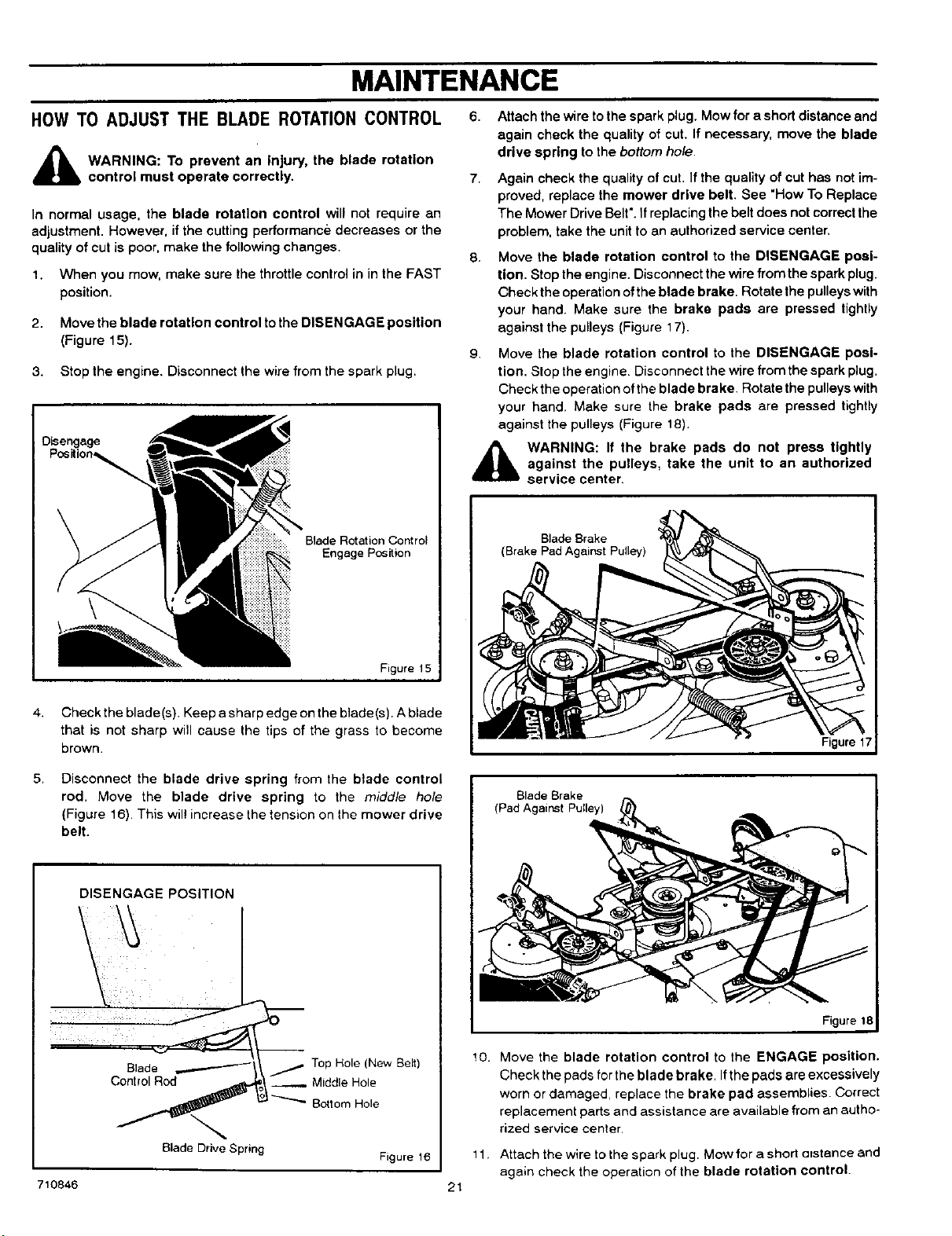
HOW TO ADJUST THE BLADE ROTATIONCONTROL
,_ WARNING: To prevent an Injury, the blade rotation
control must operate correctly.
In normal usage, the blade rotation control will not require an
adjustment. However, if the cutting performance decreases or the
quality of cut is poor, make the following changes.
1. When you mow, make sure the throttle control in in the FAST
position.
2. Move the blade rotation control to the DISENGAGE position
(Figure 15).
3. Stop the engine, Disconnect the wire from the spark plug.
Blade Rotation Control
Engage Pc_ition
Figure 15
4. Check the blade(s). Keep a sharp edge on the blade(s). A blade
that is not sharp will cause the tips of the grass to become
brown.
6. Attach the wire tothe spark plug. Mow for a short distance and
again check the quality of cut. If necessary, move the blade
drive spring to the bottom hole.
7,
Again check the quality of cut. If the quality of cut has not im-
proved, replace the mower drive belt. See "How To Replace
The Mower Drive Belt".If replacingthe beltdoes notcorrect the
problem, take the unitto an authorized service center.
8. Move the blade rotation control to the DISENGAGE posi-
tion. Stop the engine. Disconnect the wire from the spark plug.
Check the operation ofthe blade brake. Rotate the pulleyswith
your hand. Make sure the brake pads are pressed tightly
against the pulleys (Figure 17).
g.
Move the blade rotation control to the DISENGAGE posi-
tion. Stop the engine Disconnect the wire from the spark plug.
Check the operation ofthe blade brake. Rotate the pulleyswith
your hand. Make sure the brake pads are pressed tightly
against the pulleys (Figure 18).
,_ WARNING: If the brake pads do not press tightly
against the pulleys, take the unit to an authorized
service center.
Blade Brake
(Brake Pad Against Pulley)
Figure 17
5.
Disconnect the blade drive spring from the blade control
rod. Move the blade drive spring to the middle hole
(Figure 16). This wil! increase the tension on the mower drive
belt.
DISENGAGE POSITION
\
\
_Top Hole (New Belt)
Control Rod __ M,ddle Hole
,_t_ Bottom Hole
Blade Drive Spring Figure 18
710846
21
Blade Brake
(Pad Against Pulley)
Figure 18
to. Move the blade rotation control to the ENGAGE position.
Check the pads forthe blade brake. Ifthe pads are excessively
worn or damaged, replace the brake pad assemblies. Correct
replacement parts and assistance are available from an autho-
rized service center,
11. Attachthewiretothesparkplug. Mowforashort atstanceand
again check the operation of the blade rotation control.

MAINTENANCE
12. When you move the blade rotation control to the
DISENGAGE position, all movement will stop within five se-
conds. If there is movement of the belt or the blades continue
to rotate, engage and disengage the blade rotation control
five times to remove any excess rubber from a new mower
drive belt. If you need assistance, take the unit to an autho-
rized service center.
13. If you replace the mower drive belt, move the blade drive
spring to the top hole (Figure 16).
710846 22

MAINTENANCE
HOW TO CHECK AND ADJUST THE DRIVE BRAKE
Completely push the brake pedal forward. Set the parking brake,
Move the automatic drive disconnect to the PUSH position. Push
the unit. If the rear wheels rotate, adjust or replace the brake pads,
Adjust the drive brake as follows,
1. The location of the drive brake is on the right side of the
gearbox (Figure 19).
2. Make sure the parking brake is set and the automatic drive
disconnect is in the PUSH position. Turn the hex nut in a
clockwise direction until the rear wheels do not turn when the
unit is pushed forward,
3.
4.
Release the parking brake and push the unit. If the unit does not
roll, turn the hex nut in a counterclockwise direction until the
unit rolls.
Set the parking brake, Push the unit. If the rear wheels do not
turn, the drive brake is correctly adjusted. Release the parking
brake.
WARNING: If you cannot correctly adjust the drive
brake, replace the brake pads. Correct replacement
parts and assistance are available from an autho-
rized service center.
HOW TO CHECK AND ADJUST THE CLUTCH
If the motion drive belt is loose, the clutch will slip when; (1) going
up a hill, (2) pulling a heavy load, or (3) the unit will not move forward.
Adjust the clutch as follows.
7 tf the beit still slips after the clutch has been adjusted, then the
motion drive belt is worn or damaged and must be replaced.
See "How To Replace The Motion Drive Belt".
,&
WARNING: Before you make an inspection, adjust-
ment, or repair to the unit, disconnect the wire to the
spark plug. Remove the wire from the spark plug to
prevent the engine from starting by accident.
1.
2
3
4
Check the routing of the motion drive belt. Make sure the belt
is installed correctly and is inside all the belt guides
Remove the cotter pin, washer, and brake spring from the
adjustable nut (Figure 20).
Disconnect the adjustable nut from the brake lever assembly
and the parking brake latch.
Use the cotter pin removed in step 2. Hold the cotter pin at the
back of the slot and move the brake lever assembly rearward
against the cotter pin. This will set a 1/8 inch (3 mm) gap be-
tween the brake lever assembly and the back of the slot
(Figure 20)
5 Turn the adjustable nut until the nut will fit through the hole in
the brake lever.
6 Assemble the adjustable nut to the parking brake latch,
brake lever and brake spring Fasten w_th the washer and
cotter pin
• 10848
Brake Spring
23
Cotter Pin
/Clutch Rod
Adjustable Nut
Brake Lever
Assembly
C_gure 20

MAINTENANCE
HOWTO ADJUST THE SPEED CONTROL PEDAL
If the unit will not go into REVERSE or if the unit moves very slowly
in REVERSE, adjust the speed control pedal as follows
1 Stop the engine.
2 Set the parking brake.
3 Remove the hair pin from the adjuster nut (Figure 21). Dis-
connect the adjuster nut from the yoke assembly.
4.
Rotate the adjuster nut one turn in the direction shown in
Figure 21.
NOTE: Too much adjustment will cause REVERSE speed
to be too fast and the FORWARD speed to be reduced.
5. Attach the adjuster nut to the yoke assembly with the hair pin.
6. To check the adjustment, drive the unit If the adjustment is cor-
rect, the unit will now go into REVERSE
IMPORTANT: If you need assistance, go to the nearest
Authorized Service Center. They have the equipment and
experience to make the adjustment.
Hair Pin
Adjuster Nut
Speed Control Pedal
Yoke Assembly
Figure 21
MAINTENANCE FREE BATTERY
HOW TO REMOVE THE BATTERY
To charge or clean the battery remove the battery from the unit as
follows
\.
,a,
WARNING: To prevent sparks, disconnect the black
battery cable from the negative (-) terminal before you
disconnect the red cable.
WARNING: The battery contains sulfuric acid which is
harmful to the skin, eyes and clothing. Ifthe acid gets
on the body or clothing, wash with water.
1.
2
3
Disconnect the black cable from the negative (-) terminal
(Figure 22)
Disconnect the red cable from the positive (+) terminal.
Lift the battery tray and the battery out of the unit
HOW TO CLEAN THE BATTERY
1 Remove the battery
2 Wash the battery with a solution of one gallon of water and four
tablespoons of baking soda (sodium bicarbonate) Make sure
the solution does not get into the battery cells
3 Clean the terminals and the ends of Ihe cables with a w_re
brush
4 Install the battery
5 To prevent corrosion, apply grease to the battery terminals
HOW TO CHARGE THE BATTERY
710846
WARNING: When you charge the battery, do not
smoke. Keep the battery away from any sparks. The
fumes from the battery acid ea¢_cause an explosion.
24
1 Before you charge the battery, remove the battery
2 To charge the battery, use a 12 volt battery charger Charge at
a rate of 6 amperes for 1 hour
3 Install the battery,
WARNING: To prevent sparks, fasten the red cable to
the positive (+) terminal before you connect the black
cable.
4 Fasten the red cable to the positive (+) terminal with the fas
teners as shown
5 Fasten the black cable to the negative (-) terminal with the fas-
teners as shown
I Battery Positive (+1 I
Date Code Terminal
Wing
Carriage Bolt
/
Black Cable
Battery
Battery Tray
Carnage Bolt
Figure 22
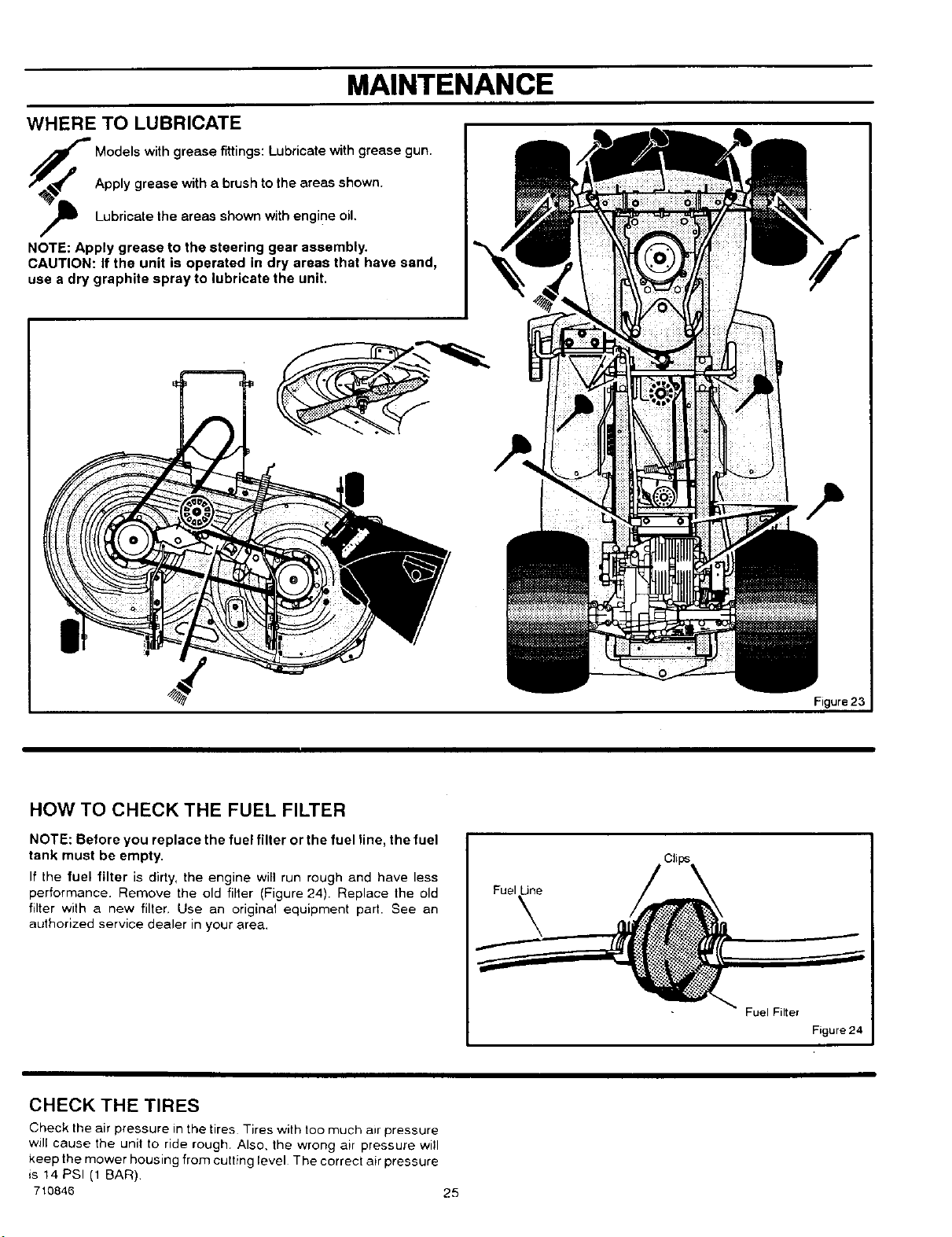
MAINTENANCE
WHERE TO LUBRICATE
NOTE: Apply grease to the steering gear assembly.
CAUTION: If the unit is operated in dry areas that have sand,
use a dry graphite spray to lubricate the unit.
Models with grease fittings: Lubricate with grease gun.
Apply grease with a brush to the areas shown.
Lubricate the areas shown with engine oil.
Figure 23
HOW TO CHECK THE FUEL FILTER
NOTE: Before you replace the fuel filter or the fuel line, the fuel
tank must be empty.
If the fuel filter is dirty, the engine will run rough and have less
performance. Remove the old filter (Figure 24). Replace the old
filter with a new filler. Use an original equipment part. See an
authorized service dealer in your area,
Fuel LJne
Fuel Filter
Figure 24
CHECK THE TIRES
Check the air pressure in the tires Tires with too much air pressure
will cause the unit to ride rough Also, the wrong apr pressure will
keep the mower housing from cutting level The correct air pressure
is 14 PSI (1 BAR)
710846 25

MAINTENANCE
HOW TO INSTALL THE MOWER HOUSING
HOW TO REMOVE THE MOWER HOUSING
1. Move the blade rotation control to the DISENGAGE position.
2. Move the lift lever to the level adjustment position (Figure 25).
4,
5,
6.
7.
8.
9.
WARNING: The lift lever
is spring loaded. Make
sure the lift lever is locked
In the LEVEL ADJUST-
MENT position.
Remove the hair pins and the
washers from the adjuster
arms (Figure 26), See illustra-
lions "C" and "D".
Remove the hair pins and wash-
ers from the suspension links. P_ltion Figure25
See illustrations "A" and "B".
Disconnect the extension spring from the blade control rod.
See illustration "E".
Disconnect the front hanger from the axle support. See
illustration "F".
Remove the mower drive belt from the stack pulley,
Pull the mower housing away from the right side of the unit.
Tooperate without the mower housing, move the lift lever to the
TOP position.
Level Adjustment
1. Push the mower housing under the right side of the unit.
2. Put the mower drive belt around the stack pulley. Make sure
the "V" side of the mower drive belt is against the stack pulley.
Also, make sure the mower drive belt is not twisted.
3. Attach the front hanger to the axle support with the hanger
rod, Fasten with the fasteners as shown. See illustration "F".
4. Make sure the mower drive belt is between the stack pulley
and the two belt guides, See illustration "G".
5. Attach the suspension links to the lifter assembly. Fasten
with the washers and hair pins, See illustrations "A"and "B",
6. Attach the right and the left adjuster arms to the suspension
brackets. Fasten with the washers and hair pins, See illustra-
tions "C" and "D".
7. Attach the extension spring to the blade control rod, See
illustration "E".
8. Move the blade rotation control to the ENGAGE position.
Make sure the mower drive belt is inside all the belt guides.
9. Make sure the mower housing is level. See the instructions on
"How TO Level The Mower Housing".
10 Check the operation of the blade rotation control. See the in-
structions on "How To Adjust The Blade Rotalion Control".
Lifter
Assembly
Adjuster Susper_sion
Arm Link
Ufl Lever
Blade Rotation
Control
G
MowerDrive Belt ,_
AdlusterArm
Blade
Control Rod
E
Extension
Spring
Drive Belt
Front Hanger
Hanger Rod
.F
Figure 26
710846 26

MAINTENANCE
HOW TO LEVEL THE MOWER HOUSING
Ifthe mower housing is level, the blade will cut easier and the lawn
wilt look better.
WARNING: Before you make an inspection, adjust-
ment, or repair to the unit, disconnect the wire to the
spark plug. Remove the spark plug wire to prevent
the engine from starting by accident.
1. Make sure the unit is on a hard flat surface.
2. Check the air pressure in the tires. If the air pressure is incor-
rect, the mower housing will not cut level. Make sure the tires
are inflated to 14 PSI. (1 BAR).
3. Some models have gauge wheels on the mower housing, if
equipped, remove the gauge wheels
4. Open the cover.
5. Move the lift lever to the LEVEL ADJUSTMENT position
(Figure 27).
,_ WARNING: The lift lever is spring loaded. Make sure
the lift lever is locked in the LEVEL ADJUSTMENT
position.
6. Loosen the left and right adjuster knobs. Push down on each
side of the mower housing. Make sure both sides of the mower
housing are setting on a flat surface
Lift Lever
Cutting Height Positions
Figure27
Figure 28
7. Tighten the left and right adjuster knobs.
8. Raise the lift lever from the LEVEL ADJUSTMENT position to
a CUTTING HEIGHT position (Figure 29).
9. Close the cover.
10. If equipped, install the gauge wheels
11 Mowforashorldistance Iftheheightofcutisnotlevel. repeat
the above steps
CAUTION: Do not operate with the mower housing in the
LEVEL ADJUSTMENT position. If you operate in the LEVEL
ADJUSTMENT position, the mower housing and blades can be
damaged.
710848
Cover
27
LiftLever
Cutting Height Positions

MAINTENANCE
HOWTO REPLACE THE MOTION DRIVEBELT
REMOVAL
1. Remove the mower housing, See the instructions on "How To
Remove The Mower Housing"
2, Completely push the pedal forward and engage the parking
brake.
3. Remove the idler pulley (Figure 30).
4. Remove the belt guide at the middle idler pulley
5. Remove the motion drive belt from the drive pulley.
6. Disengage the parking brake.
7 Remove the motion drive belt from the V-idler pulley
8. To remove the motion drive belt fromthe stack pulley, pullthe
front end of the belt under the stack pulley and then back
between the stack pulley and the steering plate (Figure 31).
9. Remove the motion drive belt. A correct replacement part or
assistance is available from an Authorized Service Center in
your area.
INSTALLATION
1. Slide the motion drive belt between the stack pulley and the
belt guides (Figure 31). Install the motion drive belt on the
top pulley of the stack pulley Make sure the "V" side of the belt
is against the pulley.
2. Push the motion drive belt through the opening between the
steering plate and the engine plate. Make sure the motion
drive belt is on the left side of the steering shaft assembly
Install the end of the motion drive belt around the drive pulley
(Figure 30)
Install the motion drive belt on the V-idler pulley
Completely pusl_ the pedal forward and engage the parking
brake
3.
4.
5.
6.
Put the belt around the idler pulley. Assemble the idler pulley
Fasten the idler pulley with the hex nut Make sure the flat side
of the belt is against the idler pulley. Also, make sure the belt
is not twisted.
7. Disengage the parking brake.
8 Install the belt guide at the middle idler pulley. Make sure the
back of the motion drive belt is against middle idler pulley.
9. Check the routing of the motion drive belt (Figure 32). Make
sure the motion drive belt is installed correctly on the idler
pulleys
10 Before you use the unit, check the adjustment of the clutch See
the instructions "How To Check And Adjust The Clutch".
11. Install the mower housing See the instructions "How To Install
The Mower Housing"
V Idler Middle Idler
Pulley Pulley
Drive
Pulley
Motion
Drive Belt
Belt Guide
Idler Pulley Figure 30
__ Steertn
Idler Pulleys
Stack Pulley
Drive Pufley
\
Motion Drive Belt
Belt Guide
Figure 32
710846 28

MAINTENANCE
HOW TO REPLACE THE MOWER DRIVE BELT
1.
2.
3.
4.
5.
Remove the mower housing. See the instructions on "How To
Remove The Mower Housing".
Pull the belt retainer away from the idler pulley and remove
the mower drive belt (Figure 17).
Pull the belt retainer away from the right mandrel pulley and
remove the mower drive belt.
Pull the belt retainer away from the left mandrel pulley and
remove the mower drive belt,
NOTE: Replace the mower drive belt with an original
equipment belt from an authorized service center.
Install the new mower drive belt. Pull the belt retainer away
from the right mandrel pulley Put the belt around the right
mandrel pulley.
6.
7.
Pull the belt retainer away from the left mandrel pulley. Put
the belt around the left mandrel pulley.
Pull the belt retainer away from the idler pulley. Put the flat
side of the mower drive belt around the idler pulley,
8,
9,
Make sure the "V" side of the mower drive belt is against the
mandrel pulleys as shown.
Install the mower housing. See the instructions on "How To
Install The Mower Housing"
10. Before you mow, check the blade rotation control. See the in-
structions on "How To Adjust The Blade Rotation Control".
Belt Retainer Left Mandrel Pulley
Right Mandrel Pulley
Belt Retainer
Idler Pulley
Mower Drive Belt Figure 33
710846 29

MAINTENANCE
HOW TO REPLACE THE FUSE 3
If the fuse is blown, the engine will not start. The location of the fuse
is next to the battery. Remove the fuse and replace with a 15 amp.
automotive fuse (Figure 34).
15 amp
Automotive Fuse
Figure
34
HOW TO REPLACE THE LIGHT BULB
2.
Raise the tractor hood.
Turn the light socket until the tabs on the socket align with the
notches in the bezel (Figure 35) Remove the light socket
Turn the light bulb and remove the bulb
Install a new light bulb. Align the light socket with the notches
in the bezel and turn the light socket to lock in position.
Ught Socket
Figure 35
HOW TO CLEAN THE MOWER HOUSING
l_ WARNING: Before you clean the mower housing,
stop the engine and disconnect the wire to the spark
plug.
Grass and other debris on top of the mower housing can keep the
belt from working correctly. For safety and correct operation,
frequently clean the t_p of the mower housing. Remove grass and
debris from around the pulleys and other moving parts.
1 Move the lever for the blade rotation control to the ENGAGE
position
2 Clean the top of the mower housing
3 Move the lever for the blade rotation contro! to the
DISENGAGE position,
4 Again clean the top of the mower housing.
5. After you cut the grass, clean the bottom of the mower housing.
STORAGE (over 30 days)
At the end of each year, prepare the unit for storage as follows
THE ENGINE
For storage information, see the the engine manufacturer's
instructions
THE BATTERY
! Remove the battery.
2 Clean the battery terminals of any deposits.
3. Charge the battery. See the instructions on "How To Prepare
And Charge The Battery".
4 Store the battery in a cool, dry place
NOTE: After a tong time in storage, charge the battery.
THE FUEL SYSTEM
,&
710846
WARNtNG: Do not drain the gasoline inside a build-
ing or near a fire. Do not smoke because the fumes
from the fuel can cause an explosion.
3O
1 Start the engine
2 Run the engine until the fuel tank and the carburetor are out of
fuel and the engine stops.
3 Do not leave fuel in the fuel tank or the carburetor. The fuel can
damage the function of the fuel system. Some models have a
fuel drain (Figure 36). Hold a cloth under the fuel drain Push
the fuel drain until the carburetor is empty
4. After storage, make sure you use fresh fuel.
Fuel Drain
CLEAN THE UNIT
1 Clean the dirt and grass from the engine
2. Clean the mower housing.
LUBRICATE THE UNIT
See the 'Lubrication" instructions rn this book
Figure 36

TROUBLE SHOOTING CHART
PROBLEM: The engine will not start.
1 Follow the steps, "How To Start The Engine" in this book.
2. Electric-Start Models: Clean the battery terminals. Tighten the
cables,
3 Drain the fuel tank, Clean the fuel line. Replace the fuel filter.
4. Remove the spark plug(s). Move the throttletothe SLOW posi-
tion. Turn the ignition key to the ON position.Try to startthe en-
gine several times, install the spark plug.
5. Replace the spark plug.
6. Adjust the carburetor,
PROBLEM: The engine will not turn over.
1. Follow the steps, "How To Start The Engine" in this book.
2. Electric-Start Models: Check the level of the acid in the battery.
Ifneeded, add water. Charge the battery.
3. Replace the fuse.
4. Check the wiring harness for damage or a loose connection.
Repair the damaged wire.
5. Electric-Start Models: reptacethe solenoid. Recoil-Start Mod-
els: reptace the module.
PROBLEM: The engine is difficult to start.
1. Adjust the carburetor.
2. Replace the spark plug.
3 Replace the fuel filter
PROBLEM: The engine does not run smooth or has a
loss of power.
1. Check the oil.
2 Clean the air filter
3. Clean the air screen
4. Replacethe spark plug
5. The engine is working too hard. Use a lower gear
6. Adjust the carburetor
7. Replace the fuel filter.
PROBLEM: The engine does not run smooth at fast
speed.
1 Replace the spark plug.
2. Adjust the throttle control
3. Clean the air filter.
4. Replacethe fuel filter
PROBLEM: The engine stops when the blades are
engaged.
1 To activate the seat sensor, always sit in the middle of the seat.
2 Check the wiring harness for damage or a loose connection
Repair the damaged wire
PROBLEM: On slopes, the engine stops.
1. Mow up and down slopes Never mow across a slope
2 To activate the seat sensor, always sit in the middle of the seat.
PROBLEM: The engine will not idle.
1 Replace the spark plug
2. Clean the air filter.
3. Adjust the carburetor.
4, Adjust the throttle control
5. Drain the fuel tank. Clean the fuel line. Replace the fuel filter.
PROBLEM: A hot engine causes a decrease in power.
1 Clean the air screen,
2. Check the oil.
3. Adjust the carburetor.
4. Replace the fuel filter.
PROBLEM: Excessive vibration.
1. Replace the blade.
2. Check for loose engine bolts,
3. Decrease the air pressure in the tires
4. Adjust the carburetor.
5, Check for a damaged belt or damaged pulley. Replace the
damaged parts.
PROBLEM: The grass does not discharge correctly.
1. Stop the engine. Clean the mower housing.
2. Raise the height of cut,
3. Replace or sharpen the blade(s)
4. Move the shift lever to a slower speed.
5. Move the throttle control to the FAST position.
6. Replace the spring for the blade idler.
PROBLEM: The mower housing does not cut level.
1. Check the air pressure in the tires,
2. Adjust the level of the mower housing.
3. Check the front axle If the front axle does not freely pivot, loos-
en the axle bolt(s).
PROBLEM: The mower blades will not rotate.
1. Check the mower drive belt, Make sure the belt is installed cor-
rectly.
2. Replace the mower drive belt
PROBLEM: The unit will not move when the brake is
released and the speed control pedal is depressed.
1 Check the motion drive belt Make sure the belt is installed
correctly.
2, Adjust the clutch.
3. Replace the motion drive belt
4 Release the Automatic Drive Disconnect under the seat
PROBLEM: The unit moves slower or stops when the
speed control pedal is depressed.
1. Adjust the clutch.
2. Replacethe motion drive belt,
PROBLEM: When the brake pedal is released, belt noise
can be heard.
1 Temporary belt noise does not change the operation of the unit
If belt noise is continuous, check the routing of the belt. Make
sure the belt is inside all belt guides,
2 if the noise is continuous, adiust the clutch.
PROBLEM: The rear wheels spin over uneven terrain.
1. Check the front axle. If the front axle does not freely pivot, loos-
en the axle bolt(s)
710846 3t
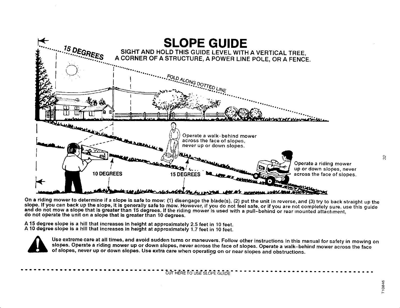
- SLOPE GUIDE
"";'-..l..b'.p_G/_.=_,_ SIGHT AND HOLD THIS GUIDE LEVEL WITH A VERTICAL TREE,
I ...... :._.._ A CORNER OF A STRUCTURE, A POWER LINE POLE OR A FENCE.
oo .
Q
1
1
I
Operate a walk-behind mower
across the face of slopes,
never up or down slopes.
10 DEGREES 15 DEGREES
Operate a riding mower
up or down slopes, never
across the face of slopes.
e)
On a riding mower to determine if a slope is safe to mow: (1) disengage the blade(s), (2) put the unit in reverse, and (3) try to back straight up the
slope. If you can back up the slope, it is generally safe to mow. However, if you do not feel safe, or if you are not completely sure, use this guide
and do not mow a slope that is greater than 15 degrees. If the riding mower is used with a pull-behind or rear mounted attachment,
do not operate the unit on a slope that is greater than 10 degrees.
A 15 degree slope is a hill that increases in height at approximately 2.5 feet in 10 feet.
A 10 degree slope is a hill that increases in height at approximately 1.7 feet in 10 feet.
Use extreme care at all times, and avoid sudden turns or maneuvers. Follow other instructions in this manual for safety in mowing on
slopes. Operate a riding mower up or down slopes, never across the face of slopes. Operate a walk-behind mower across the face
of slopes, never up or down slopes. Use extra care when operating on or near slopes and obstructions.
................................. E_rT__R'E_o'u's_S'LGP'E_GD'E.................................
co
o
p_
PARTS DISTRIBUTORS
BEBCO, INC.
2221 2nd. Ave.
South Birmingham, Ala. 35233
(205) 251-4600
1-800-828-8094
Alabama, Georgia, Florida
BILLIOU'S INC.
1343 South Main
Porterville, CA 93257
(209) 784-4102
TOLL # 1-800-245-5468
FAX # 1-800-266-7337
Arizona, California, Nevada, Hawaii
BROWN & WISER, INC.
9991 S.W. Avery Street
P.O. Box 1109
Tualatin, OR. 97062
(503) 692-0330
1-800-882-4782
Alaska, Oregon, Washington,
Montana (counties Flathead, Lake,
Lincoln, Mineral, Missoulo, Ravalli,
Sanders), Idaho (counties Ada, Adams,
Benewah, Boise, Bonner, Boundry,
Canyon, Clearwater, EImore, Gem,
Idaho, Kooten, Latah, Lewis, NEZ Perce,
Owyee, Payette, Shoshone, Valley,
Ravalli, Washington)
CHILTON AIR COOLED ENGINE
319 4th Ave, South
P.O. Box 150806
Nashville, TN 37215
(615) 254-1634
1-800-621-6934
Tennessee, Arkansas (counties Clay.
Craighead, Crittendan, Cross, Greene,
Jackson, Lawrence, Lee Mississippi,
Monroe, Phillips, Poinsett, Randolph, St.
Francis, Woodruff), Mississippi
(counties Desota, Panola, Tare, Tunica,
Quitman), Missouri (counties Dunkin,
New Madrid, Pemiscot), Virginia
(counties Bland, Buchanan, Dickerson,
Lee, Russell, Scott, Smyth, Tazewell,
Washington, Wise)
FRANK EDWARDS €O.
3653 Sl 500 West
P.O. Box 2158
Salt Lake City, UT. 84115
(801) 281-4660
1-800-366-4563
Colorado, Utah, Wyoming, Montana
(all counties except Brown and Wiser),
Idaho (counties Bannock Bearlake,
Bingham, Blaine, Booneville, Butte, Camas,
Caribou, Cassia, Custer, Franklin, Fremont,
Gooding, Jefferson, Jererne, Lamhi,
Lincoln, Madison, Minidoka, Oneida,
Power, Teton, Twin Falls)
GARDNER, INC.
1150 Chesapeake Ave.
Columbus, OH. 43212
(614) 488-7951
1-800-848-8946
Indiana, Kentucky, Michigan (except
Upper Peninsula), Ohio, West Virginia,
Western Pennsylvania with zip codes
up to and including 16999
ENGINES SOUTHWEST
215 Spring St
P.O. Box 87
Shreveport, LA. 71161-0067
(318) 222-3871
1-800-388-6995
Louisiana, Mississippi (except these
counties: Desota, Pano[a, Tare, Tunica,
Quitman), Arkansas (except these
counties: Clay, Craighead, Crittendan.
Cross, Greene, Jackson, Lawrence, Lee,
Mississippi, Monroe, Phillips, Poinsett,
Randolph, St. Francis, Woodruff,
Hempstead, Howard, Lafayette, Little
River, Miller, Nevada, Pike, Sevier)
GULF COAST ENGINE, INC.
4202 Russell Dr.
P.O. Box 9724
Corpus Christi, TX 78408
(512) 888-6999
1-800-825-6999
New Mexico, Oklahoma, Texas,
Arkansas (counties Hempstead,
Howard, Lalayetle, Litlle River, Miller,
Nevada. Pike, Sevier)
OSCAR WILSON ENGINE &
PARTS
826 Lone Star Drive
O'Fallon, MO. 63366
(314) 978-1313
1-800-873-6722
Illinois (S. of Hwy. 80), Iowa, Ne-
braska, Kansas, Missouri(all counties
except Dunkin, New Madrid, Pemiscot)
CPT CANADA POWER TECHNOL-
OGY LTD.
161 Watline Avenue
Mississauga, Ontario L4Z 1P2
Phone: 905-890-6900
1-800-861-9559
Canada
R.B.I. CORPORATION
P.O. Box 9318
Richmond, VA. 23227
(804) 550-2210
1-800-888-7149
Connecticut, Main, Massachusetts,
New Hamphire, Rhode Island, Ver-
mont, New York, New Jersey, North
and South Carolina, Maryland, Dela.
ware, District of Columbia, Virginia (all
cuonties except Bland, Buchanan,
Dickerson, Lee, Russell, Scott, Smyth,
Tazewell, Washington, Wise),
Pennsylvania, zips 17000 & up
WISCONSIN MAGNETO
4727 N. Teutonia Ave.
P.O, Box 9218
Milwaukee, WI. 55303
(414) 445-2800
1-800-733-7388
Illinois (N. o1 Hwy. 80) Michigan (Upper
Peninsula), Minnesota, Wisconsin,
North & South Dakota
710846
33
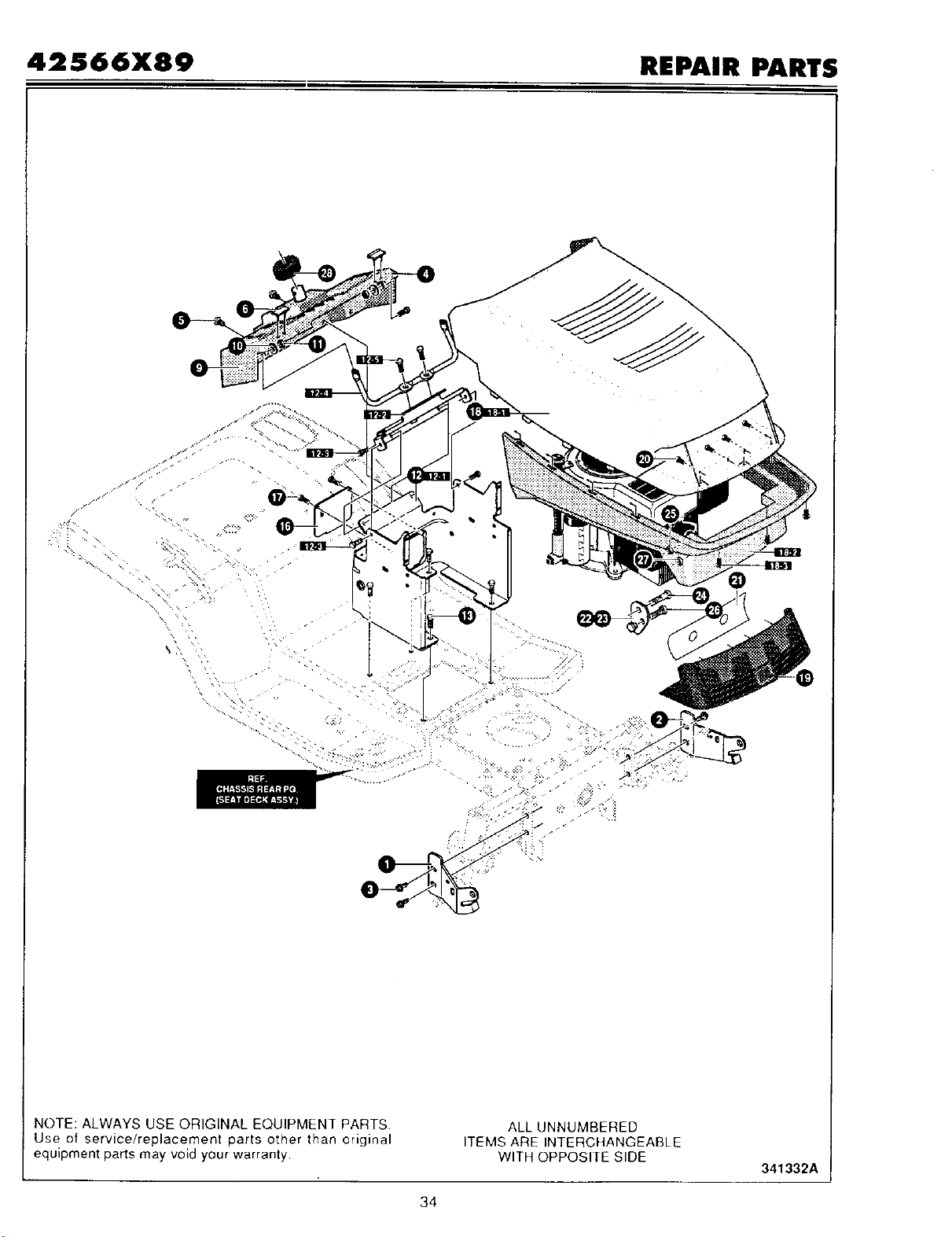
42 $66X89 REPAIR PARTS
\
\
\
NOTE: ALWAYS USE ORIGINAL EQUIPMENT PARTS
Use of service/replacement parts other than original
equipment parts may void your warranty.
ALL UNNUMBERED
ITEMS ARE INTERCHANGEABLE
WITH OPPOSITE SIDE
341332A
34

42566X89 FRONT CHASSIS ASSEMBLY
KEY #
1
2
3
4
5
6
9
10
11
12
12-1
12-2
12-3
12-4
12-5
13
16
17
18
18-1
18-2
18-3
19
20
21
22
23
24
25
26
27
PART#
95411-821
95412-821
710079
94920
710282
324491
180020
120392
780029
341499-823
95425
95426
710264
95407
710264
710079
94638-823
710134
341295
341294
333337
710282
331177
300302
310534
330886-821
330887-821
23589
92059
710312
1498
710846
DESCRIPTION
BRACKET/HOOD RH
BRACKET/HOOD LH
SCREW, 5/16-18X.75HHWATAPSGIBP
DASH
SCREW, 1/4-14X .75PHPANTAPABBL
BUMPER, HOOD/DASH SIDE TOP
SCREW, 1/4-20X.75
WASHER, FLAT .281X .63X.065
NUT,I/4-20 HEX NYLOCK #71035
ASM LOWER CONSOLE
TOWER,LOWER DASH
SUPPORT, STEERING/PTO NLT
SCREW, 1/4-20X .50 WAHHTAP
ROD,DASH BRACE
SCREW, 1/4-20X .50 WAHHTAP
SCREW, 5/16-18X.75HHWATAPSGIBP
PANEL, ACCESS
SCREW, 10-16.190X.62TRUSSCR
HOOD ASSY.
HOOD
GRILLE, QUICK REL.
SCREW, 1/4-14X.75 PHPANTAP
LENS HOOD
SCREW, #10X.50 HHTAP
DECAL, REFLECTOR
BRACKET, PIVOT RH
BRACKET, PIVOT LH
BOLT, .500X.182 HHSH 5/16-18
BELLOWS-STEERING POST
SCREW, 5/16-18Xl.00
NUT, 5/16-18 REGHEXCTRLK
OWNER'S MANUAL
QTY
1
1
4
1
2
2
2
4
2
1
1
1
4
1
2
4
1
2
1
1
1
3
1
4
1
1
1
2
1
2
2
35

42566X89 REPAIR PARTS
REF.
KEY#1
NOTE: ALWAYS USE ORIGINAL EQUIPMENT PARTS.
Use of service/replacement parts other than original
equipment parts may void your warranty•
ALL UNNUMBERED
ITEMS ARE INTERCHANGEABLE
WITH OPPOSITE SIDE
341674B
36

42566X89 REAR CHASSIS ASSEMBLY
KEY
NO.
1
1-1
1-2
1-3
1-4
2
3
4
5
6
7
8
9
9-1
9-2
9-3
10
11
12
13
14
15
16
17
18
19
20
21
22
23
24
PART
NO.
341675-823
94489
94153
710079
710205
95438
95437
94069
710274
94194-823
94680
710196
341494-823
94154
94057
710264
94156
710192
710136
710093
94155
710280
710109
710079
95444
710101
94160
710281
94490
311087
311331
DESCRIPTION
ASM. LARGE SEAT DECK, FOOT
SEAT DECK, LARGE FOOT HYDRO
BRACKET, PIVOT SEAT
SCREW, 5/16-18X.75 HHWATAP
NUT, 5/16-18 WDFLLK (15X88)
FOOTREST PAD RH
FOOTREST PAD LH
CONTAINER, BATTERY
SCREW 1/4-20X.63 HHWATAPSER
PLATE, LIFT DENTENT LG.
COVER, LIFT DETENT
SCREW, 10-24X.50 TRSEG
ASM. SEAT SUPPORT
SUPPORT, SEAT
SPRING, LEAF
SCREW, 1/4-20X.50 WAHHTAP
ZINC HINGE SEAT PIVOT
NUT, PUSH CAP .375 (28X23)
SPRING, COMPRESS 4.57LGX1.17
BOLT, SHOULDER 1/4-20 NC-2A (9X55)
WASHER CUP ZINC
NUT, 1/4-20 WDFLLK 15X89
SPRING, COMPRESS 1.43LG 164X30
SCREW 5/16-18X.75 HHWATAPSGIB
SEAT, QK ADJUST
BOLT, SHOULDER 5/16-18 NC 9X56
BOLT, WING 5/16-18X.50 LG THRD
WASHER, FLAT .344X.62X.06
COVER ,DENTENT PLATE
FASTENER, RATCHET
SCREW, 1/4-15X.44/.53 HILOHHWA
QTY
1
1
1
4
4
1
1
1
2
1
1
2
1
1
1
2
1
2
1
1
1
1
2
2
1
2
2
2
1
12
3
37

42566X89 REPAIR PARTS
O
NOTE: ALWAYS USE ORIGINAL EQUIPMENT PARTS.
Use of service/replacement parts other than original
equipment parts may void your warranty.
ALL UNNUMBERED
ITEMS ARE INTERCHANGEABLE
WITH OPPOSITE SIDE
341410A
38

42S66X89 FRAME ASSEMBLY
KEY PART
NO. NO.
1 94000
2 94001
3 94184
4 94185
5 710079
6 94002
7 710079
8 94431
9 710079
10 94187
11 710079
12 94063
13 94065
14 94030
15 94180
16 710106
17 710310
18 710080
19 94015
20 710000
21 710730
22 710140
23 94019
24 94005
25 710079
26 120395
27 94003
28 710079
29 93349
30 710204
31 94066
32 710204
33 94121
34 94123
35 710312
36 710105
37 94038
38 94035
39 710079
40 94067
41 45171
42 94013
43 710079
45 94186
46 710196
47 94425
48 94434
49 710079
DESCRIPTION QTY
FRAME,RAIL RH 1
FRAME,RAIL LH 1
BRACKET, TRANSAXLE RH 1
BRACEKT, TRANSAXLE LH 1
SCREW, 5/16-18X.75HHWATAP 6
HITCH PLATE 1
SCREW, 5/16-18X.75HHWATAP 4
BRACKET, IDLER/TRUNNION SUPP 1
SCR EW 5/16-18X.75HHWATAP 3
PLATE, REAR LARGE SEAT DECK 1
SCREW 5/16-18X.75 HHWATAP 6
TUBE, LIFTER 1
BUSHING, LIFT TUBE 2
PLATE-LIFT ARM 1
ASSY, LIFT ARM LEVER 2
SCREW, 5/16-18X.50WHHTAP (26X49) 3
SCREW, 5/16-24Xl.25 2
NUT, 5/16-24 NF-2 HEXFLLK 2
BRACKET, PIVOT 1
BOLT, .562Xl .563 HHSH 3/8-16 1
FLATWASHER .4061D (17X191 ) 1
NUT, 3/8-16 HWDFLLK MACK 15X84 1
CRANK, PTO (DRILLED) 1
BRACKET, BELL CRANK 1
SCREW, 5/16-18X.75HHWATAP 2
FLATWASHER .469X.92X.065 1
PLATE, STEERING MOUNTING 1
SCREW, 5/16-18X.75HHWATAP 6
SCREW GUIDE 5/16-18 2
NUT, 5/16-18 HEXWEFLLK WHIZ 2
SCREW-GUIDE 2
NUT, 5/16-18 HEXWDFLLK WHIZ 2
SECTOR GEAR 1
BEARING, SECTOR GEAR 1
SCREW, 5/16-18Xl .00 HHC 1
NUT, 5/16-8 HKEPS 15X113 1
ASSEMBLY, BRAKE LEVER 1
BRACKET, PEDAL PIVOT 2
SCREW, 5/16-18X.75 HHWATAP 4
PIN, THREADED SHOULDER 2
NUT,3/8-16HWDFLWHIZ-LOCK 2
BRACKET, HANGER REAR 1
SCREW, 5/16-18X.75 HHWATAP 6
TOP, REAR PLATE LARGE SEAT DECK 1
SCREW 10-24X.500TRSEGI 5
ROD, TRUNNION YOKE (PEERLESS) 1
CLAMP, TRUNNION PIVOT PEERLESS 2
SCREW 5/16-18X.75HHWATAP 2
39
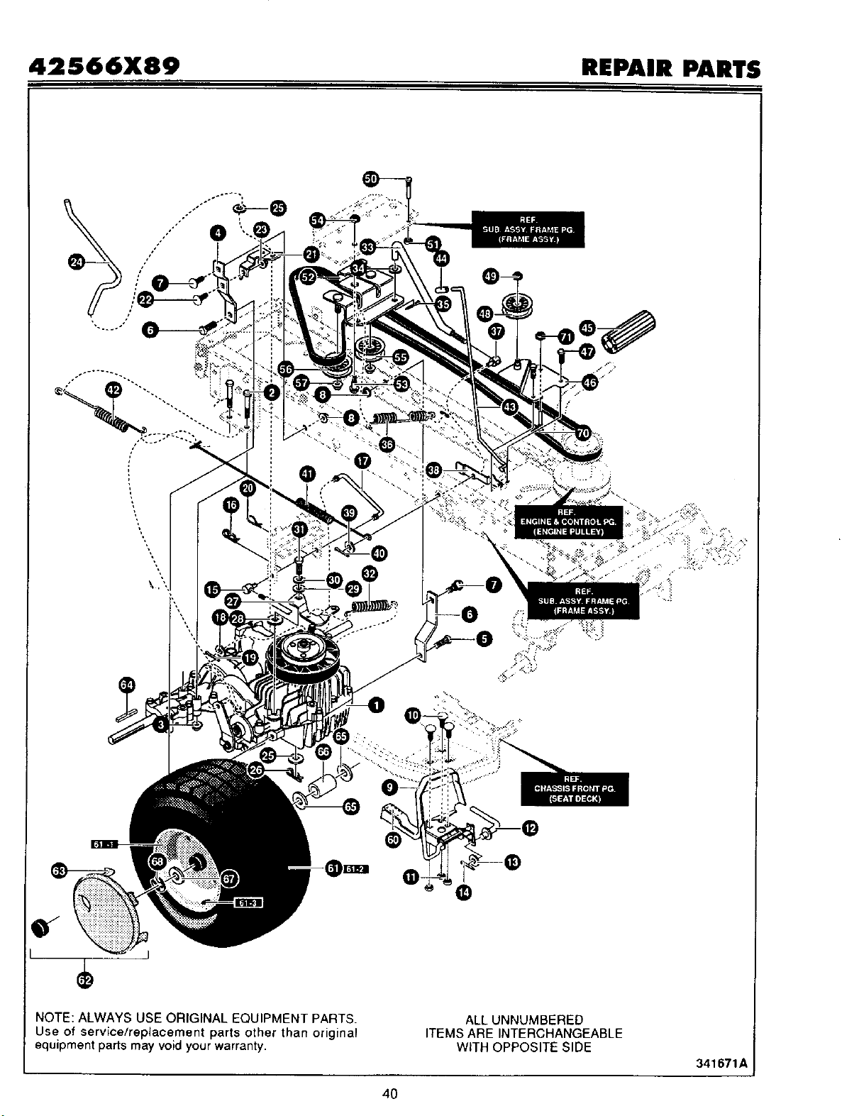
42S66X89 REPAIR PARTS
'\
\
\
\.\
O
°°_.°°
,/• .:.
NOTE: ALWAYS USE ORIGINAL EQUIPMENT PARTS.
Use of service/replacement parts other than original
equipment parts may void your warranty.
ALL UNNUMBERED
ITEMS ARE INTERCHANGEABLE
WITH OPPOSITE SIDE
341671A
4O
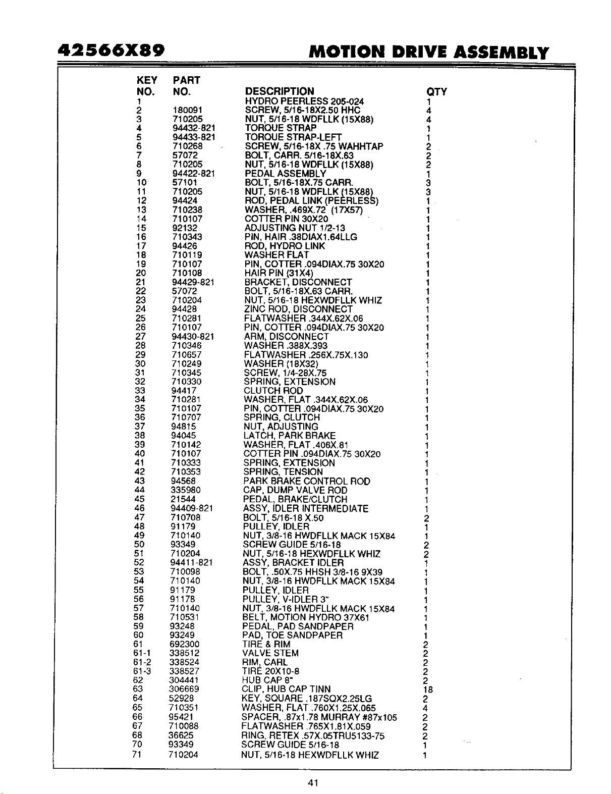
42S66X89 MOTION DRIVE ASSEMBLY
KEY PART
NO. NO.
1
2 180091
3 710205
4 94432-821
5 94433-821
6 710268
7 57072
8 710205
9 94422-821
10 57101
11 710205
12 94424
13 710238
14 710107
15 92132
16 710343
17 94426
18 71O119
19 710107
20 710108
21 94429-821
22 57072
23 71O2O4
24 94428
25 710281
26 710107
27 94430-821
28 710346
29 71O657
30 710249
31 710345
32 710330
33 94417
34 710281
35 710107
36 710707
37 94815
38 94045
39 710142
40 710107
41 710333
42 710353
43 94568
44 335980
45 21544
46 94409-821
47 710708
48 91179
49 710140
50 93349
51 710204
52 94411-821
53 710O98
54 710140
55 91179
56 91178
57 71014O
58 710531
59 93248
60 93249
61 692300
61-1 338512
61-2 338524
61-3 338527
62 304441
63 306669
64 52928
65 710351
66 95421
67 710088
68 36625
70 93349
71 7102O4
DESCRIPTION QTY
HYDRO PEERLESS 205-024 1
SCREW, 5/16-18X2.50 HHC 4
NUT, 5/16-18 WDFLLK (15X88) 4
TORQUE STRAP 1
TORQUE STRAP-LEFT 1
SCREW, 5/16-18X .75 WAHHTAP 2
BOLT, CARR. 5/16-18X.63 2
NUT, 5/16-18 WDFLLK (15X88) 2
PEDAL ASSEMBLY 1
BOLT, 5/16-18X.75 CARR. 3
NUT, 5/16-18 WDFLLK (15X88) 3
ROD, PEDAL LINK (PEERLESS) 1
WASHER, .469X.72 (17X57) 1
COTTER PIN 30X20 1
ADJUSTING NUT 1/2-13 1
PIN, HAIR .38DIAX1.64LLG 1
ROD, HYDRO LINK 1
WASHER FLAT 1
PIN, COTTER .094DIAX.75 30X20 1
HAIR PIN (31X4) 1
BRACKET, DISCONNECT 1
BOLT, 5/16-18X.63 CARR. 1
NUT, 5/16-18 HEXWDFLLK WHIZ 1
ZINC ROD, DISCONNECT 1
FLATWASHER .344X.62X.06 1
PIN, COTTER .094DIAX.75 30X20 1
ARM, DISCONNECT 1
WASHER .388X.393 1
FLATWASHER .256X.75X.130 1
WASHER (18X32) 1
SCREW, 1/4-28X.75 1
SPRING, EXTENSION 1
CLUTCH ROD 1
WASHER, FLAT .344X.62X.06 1
PIN, COTTER .094DIAX.75 30X20 1
SPRING, CLUTCH 1
NUT, ADJUSTING 1
LATCH, PARK BRAKE 1
WASHER, FLAT .406X.81 1
COFFER PIN .094DIAX.75 30X20 1
SPRING, EXTENSION 1
SPRING, TENSION 1
PARK BRAKE CONTROL ROD 1
CAP, DUMP VALVE ROD 1
PEDAL, BRAKE/CLUTCH 1
ASSY, IDLER INTERMEDIATE 1
BOLT, 5/16-18 X.50 2
PULLEY, IDLER 1
NUT, 3/8-16 HWDFLLK MACK 15X84 1
SCREW GUIDE 5/16-18 2
NUT, 5/16-18 HEXWDFLLK WHIZ 2
ASSY, BRACKET IDLER 1
BOLT, .50X.75 HHSH 3/8-16 9X39 1
NUT, 3/8-16 HWDFLLK MACK 15X84 1
PULLEY, IDLER 1
PULLEY, V-IDLER 3" 1
NUT, 3/8-16 HWDFLLK MACK 15X84 1
BELT, MOTION HYDRO 37X61 1
PEDAL, PAD SANDPAPER 1
PAD, TOE SANDPAPER 1
TIRE & RIM 2
VALVE STEM 2
RIM, CARL 2
TIRE 20X10-8 2
HUB CAP 8" 2
CLIP, HUB CAP TINN 18
KEY, SQUARE .187SQX2.25LG 2
WASHER, FLAT .760X1.25X.065 4
SPACER, .87xl .78 MURRAY #87x105 2
FLATWASHER .765Xl .81X.059 2
RING, RETEX .57X.05TRU5133-75 2
SCREW GUIDE 5/16-18 1
NUT, 5/16-18 HEXWDFLLK WHIZ 1
41

42S66X89 REPAIR PARTS
TORQUE 13-t5 FT*L81
llOil
GREASE APPLIED TO SPINDLE SHAFT
TORQUE 25.40 FT-L8 l
@
NOTE: ALWAYS USE ORIGINAL EQUIPMENT PARTS.
Use of service/replacement parts other than original
equipment parts may void your warranty.
ALL UNNUMBERED
ITEMS ARE INTERCHANGEABLE
WITH OPPOSITE SIDE
341377A
42
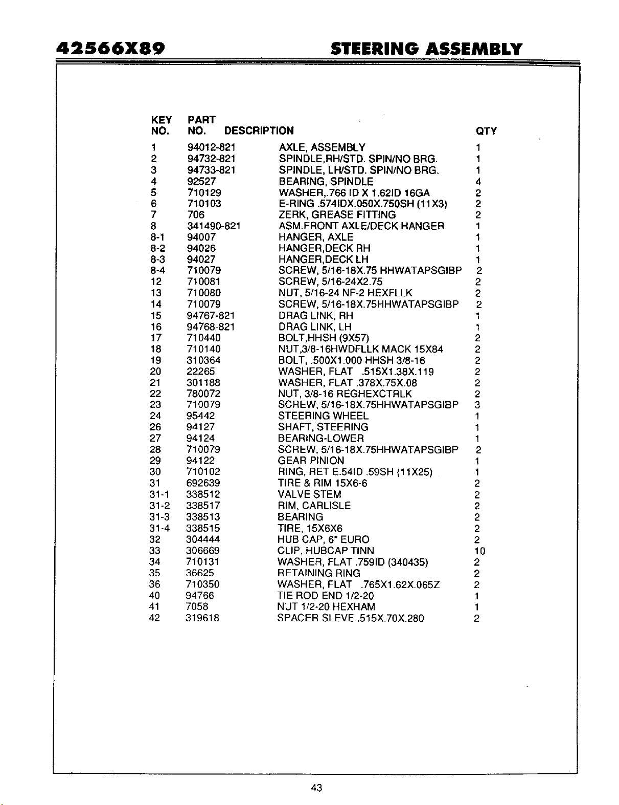
42566X89 STEERIHG ASSEMBLY
KEY PART
NO. NO. DESCRIPTION
1 94012-821
2 94732-821
3 94733-821
4 92527
5 710129
6 710103
7 706
8 341490-821
8-1 94007
8-2 94026
8-3 94027
8-4 710079
12 710081
13 710080
14 710079
15 94767-821
16 94768-821
17 710440
18 710140
19 310364
20 22265
21 301188
22 780072
23 710079
24 95442
26 94127
27 94124
28 710079
29 94122
30 710102
31 692639
31-1 338512
31-2 338517
31-3 338513
31-4 338515
32 304444
33 306669
34 710131
35 36625
36 710350
40 94766
41 7058
42 319618
QTY
AXLE, ASSEMBLY 1
SPINDLE,RH/STD. SPIN/NO BRG. 1
SPINDLE, LH/STD. SPIN/NO BRG. 1
BEARING, SPINDLE 4
WASHER,.766 ID X 1.621D 16GA 2
E-RING .5741DX.050X.750SH (11X3) 2
ZERK, GREASE FITTING 2
ASM.FRONT AXLE/DECK HANGER 1
HANGER, AXLE 1
HANGER,DECK RH 1
HANGER,DECK LH 1
SCREW, 5/16-18X.75 HHWATAPSGIBP 2
SCREW, 5/16-24X2.75 2
NUT, 5/16-24 NF-2 HEXFLLK 2
SCREW, 5/16-18X.75HHWATAPSGIBP 2
DRAG LINK, RH 1
DRAG LINK, LH 1
BOLT,HHSH (9X57) 2
NUT,3/8-16HWDFLLK MACK 15X84 2
BOLT, .500Xl .000 HHSH 3/8-16 2
WASHER, FLAT .515Xl.38X.119 2
WASHER, FLAT .378X.75X.08 2
NUT, 3/8-16 REGHEXCTRLK 2
SCREW, 5/16-18X.75HHWATAPSGIBP 3
STEERING WHEEL 1
SHAFT, STEERING 1
BEARING-LOWER 1
SCREW, 5/16-18X.75HHWATAPSGIBP 2
GEAR PINION 1
RING, RET E.541D .59SH (11X25) 1
TIRE & RIM 15X6-6 2
VALVE STEM 2
RIM, CARLISLE 2
BEARING 2
TIRE, 15X6X6 2
HUB CAP, 6" EURO 2
CLIP, HUBCAP TINN 10
WASHER, FLAT .7591D (340435) 2
RETAINING RING 2
WASHER, FLAT .765X1.62X.065Z 2
TIE ROD END 1/2-20 1
NUT 1/2-20 HEXHAM 1
SPACER SLEVE .515X.70X.280 2
43
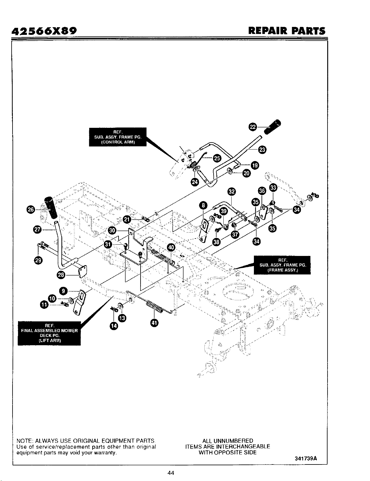
42S66X89 REPAIR PARTS
/
... . ."
NOTE: ALWAYS USE ORIGINAL EQUIPMENT PARTS
Use of service/replacement parts other than original
equipment parts may void your warranty•
ALL UNNUMBERED
ITEMS ARE INTERCHANGEABLE
WITH OPPOSITE SIDE
341739A
44
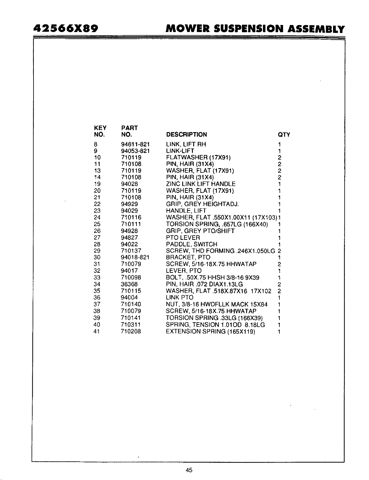
42566X89 MOWER SUSPENSION ASSEMBLY
KEY
NO.
8
9
10
11
13
14
19
20
21
22
23
24
25
26
27
28
29
30
31
32
33
34
35
36
37
38
39
40
41
PART
NO.
94611-821
94053-821
710119
710108
710119
710108
94028
710119
710108
94929
94029
710116
710111
94928
94827
94022
710137
94018-821
710079
94017
710098
36368
710115
94004
710140
710079
710141
710311
710208
DESCRIPTION QTY
LINK, LIFT RH
LINK-LIFT
FLATWASHER (17X91)
PIN, HAIR (31X4)
WASHER, FLAT (17X91)
PIN, HAIR (31X4)
ZINC LINK LIFT HANDLE
WASHER, FLAT (17X91)
PIN, HAIR (31X4)
GRIP, GREY HEIGHTADJ.
HANDLE, LIFT
1
1
2
2
2
2
1
1
1
1
1
WASHER, FLAT .550X1.00X11 (17X103)1
TORSION SPRING, .657LG (166X40) 1
GRIP, GREY PTO/SHIFT 1
PTO LEVER 1
PADDLE, SWITCH 1
SCREW, THD FORMING .246Xl.050LG 2
BRACKET, PTO 1
SCREW, 5/16-18X.75 HHWATAP 2
LEVER, PTO 1
BOLT, .50X.75 HHSH 3/8-16 9X39 1
PIN, HAIR .072 DIAX1.13LG 2
WASHER, FLAT.518X.87X16 17X102 2
LINK PTO 1
NUT, 3/8-16 HWDFLLK MACK 15X84 1
SCREW, 5/16-18X.75 HHWATAP 1
TORSION SPRING .33LG (166X39) 1
SPRING, TENSION 1.01OD 8.18LG 1
EXTENSION SPRING (165Xl 19) 1
45
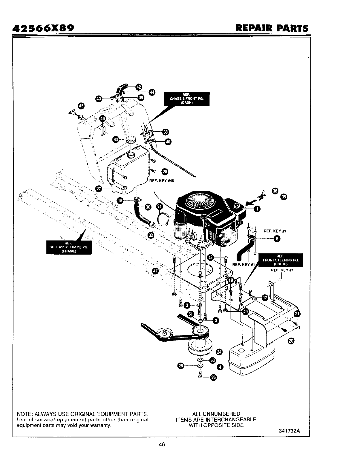
42S66X89 REPAIR PARTS
REF. KEY #45
\
REF, KEY #1
I
NOTE: ALWAYS USE ORIGINAL EQUIPMENT PARTS.
Use of service/replacement parts other than original
equipment parts may void your warranty•
ALL UNNUMBERED
ITEMS ARE INTERCHANGEABLE
WITH OPPOSITE SIDE
341732A
46
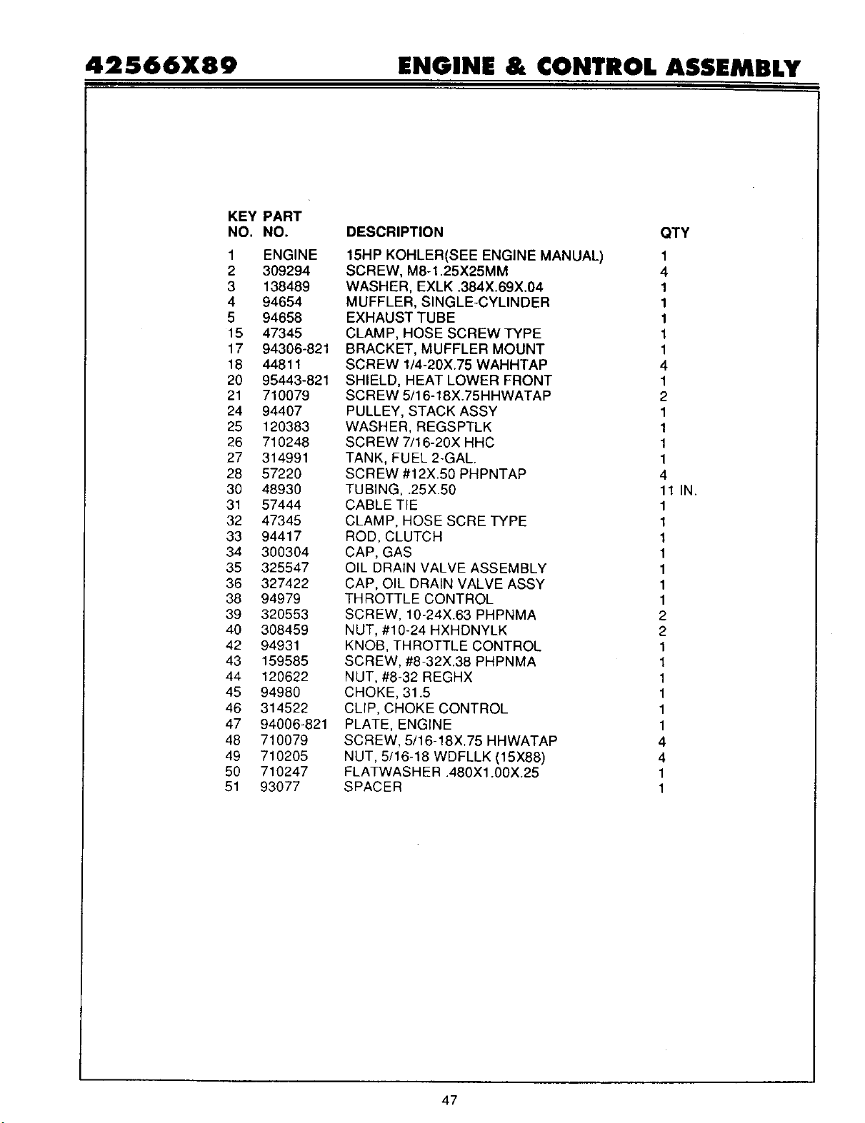
42566X89 ENGINE & CONTROL ASSEMBLY
KEY PART
NO. NO.
1 ENGINE
2 309294
3 138489
4 94654
5 94658
15 47345
17 94306-821
18 44811
20 95443-821
21 710079
24 94407
25 120383
26 710248
27 314991
28 57220
30 48930
31 57444
32 47345
33 94417
34 300304
35 325547
36 327422
38 94979
39 320553
40 308459
42 94931
43 159585
44 120622
45 94980
46 314522
47 94006-821
48 710079
49 71O2O5
50 710247
51 93077
DESCRIPTION QTY
15HP KOHLER(SEE ENGINE MANUAL) 1
SCREW, M8-1.25X25MM 4
WASHER, EXLK .384X.69X.04 1
MUFFLER, SINGLE-CYLINDER 1
EXHAUST TUBE 1
CLAMP, HOSE SCREW TYPE 1
BRACKET, MUFFLER MOUNT 1
SCREW 1/4-20X.75 WAHHTAP 4
SHIELD, HEAT LOWER FRONT 1
SCREW 5/16-18X.75HHWATAP 2
PULLEY, STACK ASSY 1
WASHER, REGSPTLK 1
SCREW 7/16-20X HHC 1
TANK, FUEL 2-GAL. 1
SCREW #12X.50 PHPNTAP 4
TUBING, .25X.50 11 IN.
CABLE TIE 1
CLAMP, HOSE SCRE TYPE 1
ROD, CLUTCH 1
CAP, GAS 1
OIL DRAIN VALVE ASSEMBLY 1
CAP, OIL DRAIN VALVE ASSY 1
THROTTLE CONTROL 1
SCREW, 10-24X.63 PHPNMA 2
NUT, #10-24 HXHDNYLK 2
KNOB, THROTTLE CONTROL 1
SCREW, #8-32X.38 PHPNMA 1
NUT, #8-32 REGHX 1
CHOKE, 31.5 1
CLIP, CHOKE CONTROL 1
PLATE, ENGENE 1
SCREW, 5/16-18X.75 HHWATAP 4
NUT, 5/16-18 WDFLLK (15X88) 4
FLATWASHER .480Xl .00X.25 1
SPACER 1
47

42566X89 REPAIR PARTS
O
NOTE: ALWAYS USE ORIGINAL EQUIPMENT PARTS.
Use of service/replacement parts other than original
equipment parts may void your warranty.
ALL UNNUMBERED
ITEMS ARE INTERCHANGEABLE
WITH OPPOSITE SIDE
341734A
48
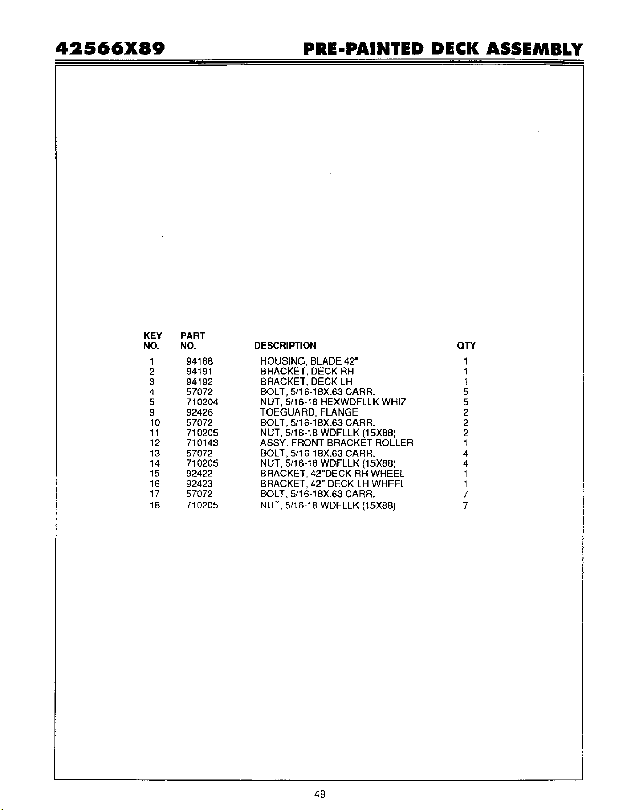
42566X89 PRE-PAINTED DECK ASSEMBLY
KEY
NO.
1
2
3
4
5
9
10
11
12
13
14
15
16
17
18
PART
NO.
94188
94191
94192
57072
710204
92426
57072
710205
710143
57072
710205
92422
92423
57072
710205
DESCRIPTION
HOUSING, BLADE 42"
BRACKET, DECK RH
BRACKET, DECK LH
BOLT, 5/16-18X.63 CARR.
NUT, 5/16-18 HEXWDFLLK WHIZ
TOEGUARD, FLANGE
BOLT, 5/16-18X.63 CARR.
NUT, 5/16-18 WDFLLK (15X88)
ASSY, FRONT BRACKET ROLLER
BOLT, 5/16-18X.63 CARR.
NUT, 5/16-18 WDFLLK (15X88)
BRACKET, 42"DECK RH WHEEL
BRACKET, 42" DECK LH WHEEL
BOLT, 5/16-18X.63 CARR.
NUT, 5/16-18 WDFLLK (15X88)
QTY
1
1
1
5
5
2
2
2
1
4
4
1
1
7
7
49
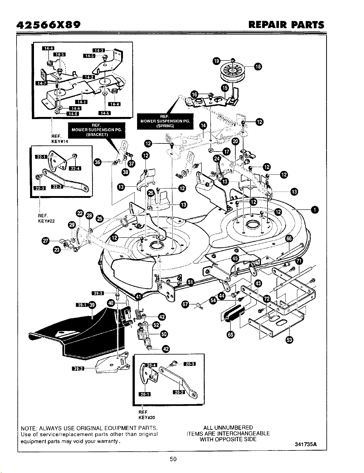
42566X89 REPAIR PARTS
REF.
KEY#14
REF.
KEY#22
I I
REF.
KEY#20
NOTE: ALWAYS USE ORIGINAL EQUIPMENT PARTS.
Use of service/replacement parts other than original
equipment parts may void your warranty.
ALL UNNUMBERED
ITEMS ARE INTERCHANGEABLE
WITH OPPOSITE SIDE
341735A
5O
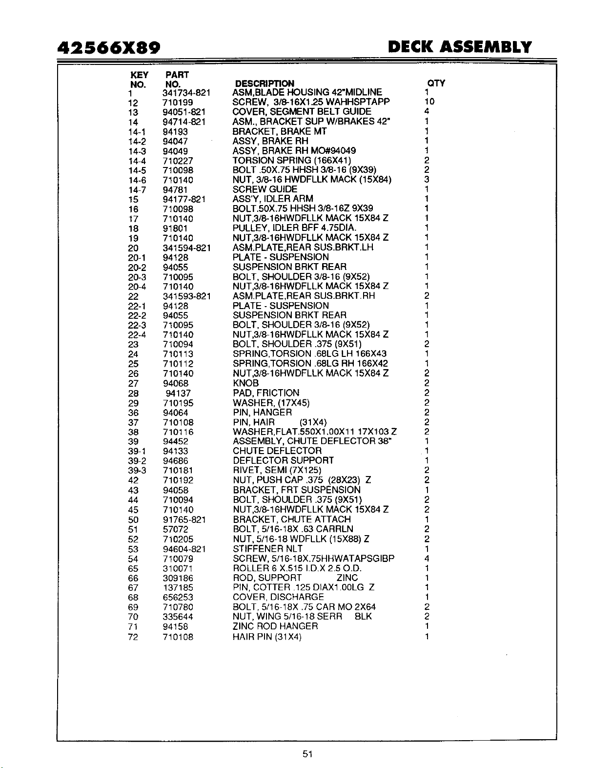
42566X89 DECK ASSEMBLY
KEY
NO.
1
12
13
14
14-1
14-2
14-3
14-4
14-5
14-6
14-7
15
16
17
18
19
2O
20-1
20-2
20-3
20-4
22
22-1
22-2
22-3
22-4
23
24
25
26
27
28
29
36
37
38
39
39-1
39-2
39-3
42
43
44
45
50
51
52
53
54
65
66
67
68
69
70
71
72
PART
NO.
341734-821
710199
94051-821
94714-821
94193
94047
94049
710227
710098
710140
94781
94177-821
710098
710140
91801
710140
341594-821
94128
94055
710095
710140
341593-821
94128
94055
710095
710140
710094
710113
710112
710140
94068
94137
710195
94064
710108
710116
94452
94133
94686
710181
710192
94058
710094
710140
91765-821
57072
710205
94604-821
710079
310071
309186
137185
656253
710780
335644
94158
710108
DESCRIPTION
ASM,BLADE HOUSING 42"MIDLINE
SCREW, 3/8-16X1.25 WAHHSPTAPP
COVER, SEGMENT BELT GUIDE
ASM., BRACKET SUP W/BRAKES 42"
BRACKET, BRAKE MT
ASSY, BRAKE RH
ASSY, BRAKE RH MO#94049
TORSION SPRING (166X41)
BOLT .50X.75 HHSH 3/8-16 (9X39)
NUT, 3/8-16 HWDFLLK MACK (15X84)
SCREW GUIDE
ASS'Y, IDLER ARM
BOLT.50X.75 HHSH 3/8-16Z 9X39
NUT,3/8-16HWDFLLK MACK 15X84 Z
PULLEY, IDLER BFF4.75DIA.
NUT,3/8-16HWDFLLK MACK 15X84 Z
ASM.PLATE,REAR SUS.BRKT.LH
PLATE - SUSPENSION
SUSPENSION BRKT REAR
BOLT, SHOULDER 3/8-16 (9X52)
NUT,3/8-16HWDFLLK MACK 15X84 Z
ASM.PLATE,REAR SUS.BRKT.RH
PLATE - SUSPENSION
SUSPENSION BRKT REAR
BOLT, SHOULDER 3/8-16 (9X52)
NUT,3/8-16HWDFLLK MACK 15X84 Z
BOLT, SHOULDER .375 (9X51)
SPRING,TORSION .68LG LH 166X43
SPRING,TORSION .68LG RH 166X42
NUT,3/8-16HWDFLLK MACK 15X84 Z
KNOB
PAD, FRICTION
WASHER, (17X45)
PIN, HANGER
PIN, HAIR (31X4)
WASHER,FLAT.550X1.00Xll 17X103 Z
ASSEMBLY, CHUTE DEFLECTOR 38"
CHUTE DEFLECTOR
DEFLECTOR SUPPORT
RIVET, SEMI (7X125)
NUT, PUSH CAP .375 (28X23) Z
BRACKET, FRT SUSPENSION
BOLT, SHOULDER .375 (9X51)
NUT,3/8-16HWDFLLK MACK 15X84 Z
BRACKET,CHUTE ATTACH
BOLT, 5/16-18X .63 CARRLN
NUT, 5/16-18 WDFLLK (15X88) Z
STIFFENER NLT
SCREW, 5/16-18X.75HHWATAPSGIBP
ROLLER 6 X.515 ID.X 2.50.D.
ROD, SUPPORT ZINC
PiN, COTTER .125 DIAX1.00LG Z
COVER, DISCHARGE
BOLT, 5/16-18X .75 CAR MO 2X64
NUT, WING 5/16-18 SERR BLK
ZINC ROD HANGER
HAIR PIN (31X4)
QTY
1
10
4
1
1
1
1
2
2
3
1
1
1
1
1
1
1
1
1
1
1
2
1
1
1
1
2
1
1
2
2
2
2
2
2
2
1
1
1
2
2
1
2
2
1
2
2
1
4
1
1
1
1
2
2
1
1
51
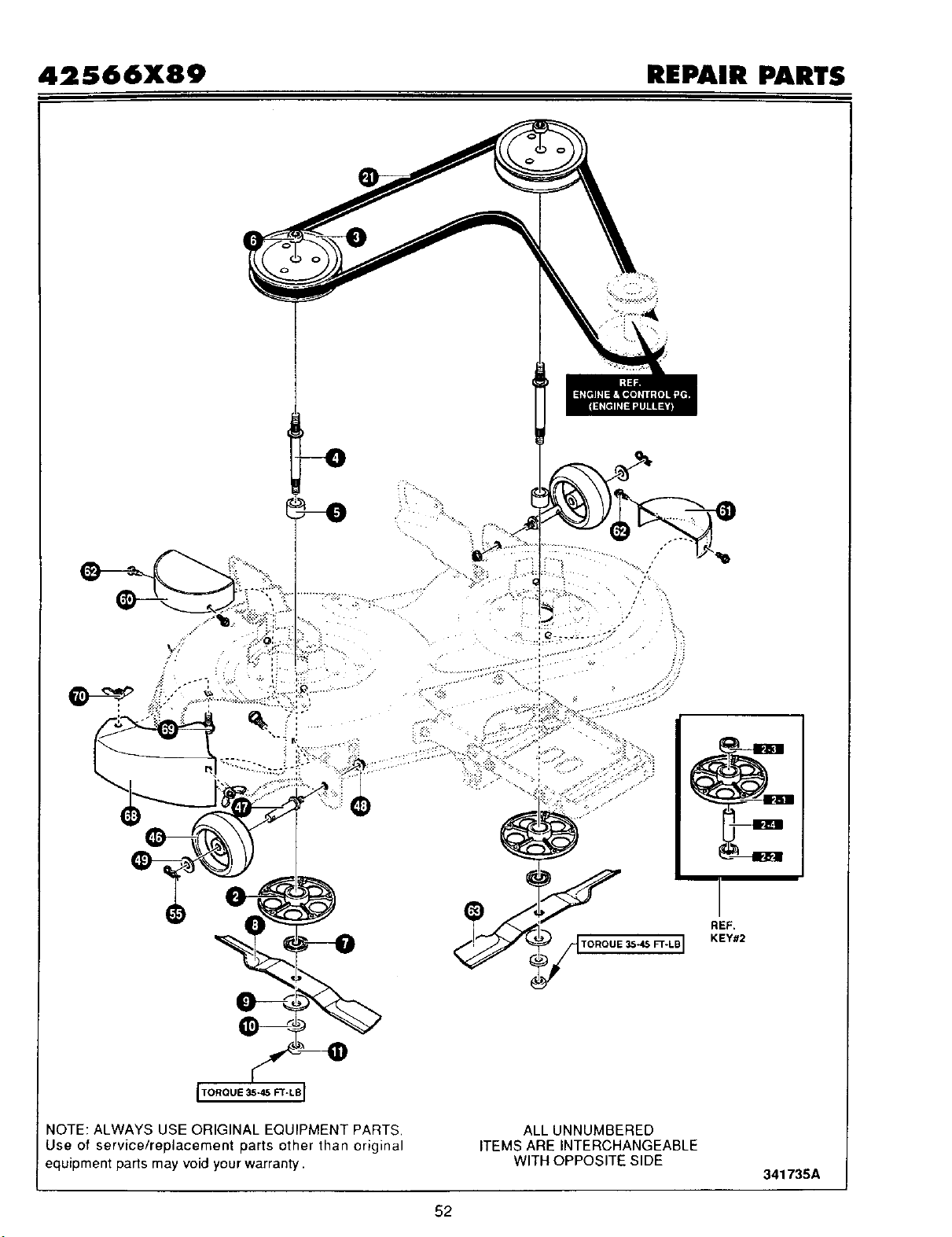
42S66X89 REPAIR PARTS
.:.*.
REF.
TORQUE _*45FT-LB I KEY#2
NOTE: ALWAYS USE ORIGINAL EQUIPMENT PARTS,
Use of service/replacement parts other than original
equipment parts may void your warranty.
ALL UNNUMBERED
ITEMS ARE INTERCHANGEABLE
WITH OPPOSITE SIDE
341735A
52
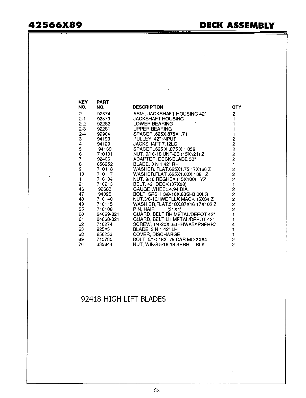
42566X89 DECK ASSEMBLY
KEY PART
NO. NO.
2 92574
2-1 92573
2-2 92282
2-3 92281
2-4 90904
3 94199
4 94129
5 94130
6 710191
7 92466
8 656252
9 710118
10 710117
11 710104
21 710213
46 92683
47 94025
48 710140
49 710115
55 710108
60 94669-821
61 94668-821
62 710274
63 92545
68 656253
69 710780
70 335644
DESCRIPTION
ASM., JACKSHAFT HOUSING 42"
JACKSHAFT HOUSING
LOWER BEARING
UPPER BEARING
SPACER .625X.875X1.71
PULLEY, 42" INPUT
JACKSHAFT 7.12LG
SPACER,.625 X .875 X 1.858
NUT, 9/16-18 UNF-2B (15X121) Z
ADAPTER, DECK/BLADE 38"
BLADE, 3 N 1 42" RH
WASHER, FLAT.625X1.75 17X166 Z
WASHER,FLAT .625Xl .00X.188 Z
NUT, 9/16 REGHEX (15X100) YZ
BELT, 42" DECK (37X88)
GAUGE WHEEL,4.94 DIA.
BOLT, SPSH 3i8-16X.63SH3.00LG
NUT,3/8-16HWDFLLK MACK 15X84 Z
WASH ER,FLAT.518X.87X 16 17X 102 Z
PIN, HAIR (31X4)
GUARD, BELT RH METAL/DEPOT 42"
GUARD, BELT LH METAL!DEPOT 42"
SCREW, 1/4-20X .63HHWATAPSERBZ
BLADE, 3 N 1 42" LH
COVER, DISCHARGE
BOLT, 5/16-18X .75 CAR MO 2X64
NUT, WING 5/16-18 SERR BLK
QTY
2
1
1
1
1
2
2
2
2
2
1
2
2
2
1
2
2
2
2
2
1
1
4
1
1
2
2
92418-HIGH LIFT BLADES
53
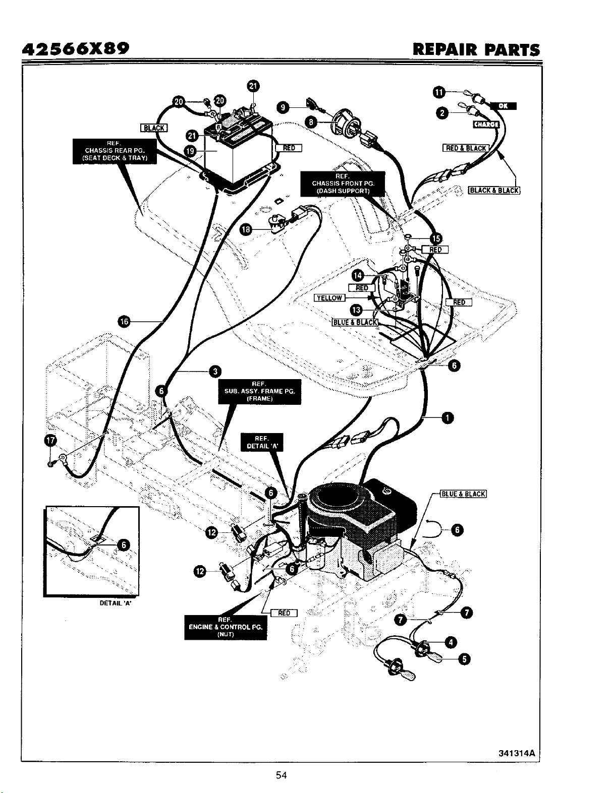
42S66X89 REPAIR PARTS
- !!
/
\
• ::_b
•I i_"_ _:" ""
i_i_."-.. _..
BLUE& BLACK]
DETAIL 'A'
::-
341314A
54

42S66X89 ELECTRICAL ASSEMBLY
KEY PART
NO. NO.
1 94745
2 94740
3 94741
4 303064
5 52572
6 57444
7 41482
8 94762
9 327350
11 57769
12 94136
13 94613
14 710133
15 710203
16 710228
17 710230
18 94159
19 302257
20 710226
21 710225
DESCRIPTION
QTY
HARNESS 14BS OHVL,H25,REBA,SUS 1
HARNESSADAPTER,OK/CHARGE IL 1
WIRE HARNESS, REAR 1
ASSY,LIGHT WIRE-l/4 TURN 1
BULB, HEADLAMP 2
TIE, CABLE BLACK NYLON 5.62L 5
PRESS CLIP,1.380LG .2551D 2
SWITCH, IGNITION DELTA 7 TERM 1
KEY,IGNITION GENERIC DELTA 1
BULB, INDICATOR 2
SWITCH LIMIT DELTA 2
SOLENOID 1
SCREW,HHWATAP 1/4X.50 2
NUT, 1/4-20 HEXNYL 15X116 2
WIRE, GROUND (24X32) 1
SCREW, 1/4-20X.75HWAT (26X213) 1
SWITCH, SEAT 1
BATTERY 12V 7 PLATE 1
BOLT, 1/4-20X.63CAR (2X82) 2
NUT, WING 1/4-20 NC (14X79) 2
SCHEMATIC WIRING
®
55

42566X89 DECAL ASSEMBLY
KEY PART
NO. NO.
1 710638
2 710639
4 710781
5 710768
6 402700
7 402701
8 322763
DESCRIPTION
DECAL HEIGHT ADJUST
DECAL
DECAL
DECAL
DECAL
DECAL
DECAL
DECK LEVEL
FOOT HYDRO INST DASH 1
HYDRO DUMP 1
CAUTION DECK LH 1
CAUTION DECK RH CUT HAND 1
OPER INST TOP FRAME 1
QTY
1
1
341749A
56

42S66X89 DECAL ASSEMBLY
KEY
NO.
1
2
3
4
6
7
8
9
10
11
12
13
14
PART
NO.
710500
710501
710514
710513
710551
710712
710510
710511
710799
710262
710261
710126
710691
DESCRIPTION
DECAL
DECAL
DECAL
DECAL
DECAL
DECAL
DECAL
DECAL
DECAL
DECAL
DECAL
DECAL
DECAL
QTY
YARDKING RH 15/42" 1
YARDKING LH 15/42" 1
PEDAL CONT RH AUTODRIVE 1
PEDAL CONT LH AUTODRIVE 1
YARD PERF KOHLER COMM 2
CUST. CARE YK. PERF 1
ALL PERF. DECK 44X6700 1
TWIN DURA-BEAM FRAME 2
ALL PERF. CUT LEVEL SYS 1
DASH RH W/CHOKE 1
DASH LH CHOKE 1
DASH CENTER OP, ASG,OK 1
PARK BRAKE(P) WHITE/BL 1
57
34163OA

NOTES
710846 58

INDEX
Throttle Control, 13
A
Adjustments
Blade Rotation Control, 21
Clutch, 23
Drive Brake, 23
Mower Housing, Level, 27
Speed Control Pedal, 24
Attachments. 13, 60
Automatic Drive Disconnect, Opera-
tion, 14
B
Battery
Charge, 24
Check, 11
Clean, 24
Install, 11
Removal, 24
Storage, 30
Belt
Motion Drive
Adjust, 23
Replace, 28
Mower Drive
Adjust, 21
Replace, 29
Blade
Inspect, 20
Remove And Install, 20
Sharpen, 20
Blade Rotation Control
Adjust, 21
Location, 12
Operation. 13
Brake Pedal, Location, 12
C
Clutch
Adjust, 23
Check. 23
Controls, Location, 12
Cutting Height
Adjust, 27
Change, 15
D
Drive Brake
Adjust, 23
Check, 23
E
Engine
Fuel, 11, 17
Oil, 11, 17
Preparation, 11
SparkArrester 11, 19
Starting, 17
Storage, 30
F
Filter, Fuel, 25
Fuel, Type, 17
Fuse, 30
H
Headlight, Replace Light Bulb, 30
Headlight Switch, Location, 12
Ignition Switch, Location, 12
L
Lift Lever
Location, 12
Operation. 15
Lubrication, Mower, 25
M
Maintenance
Battery
Charge, 24
Clean, 24
Belt
Motion Drive, 28
Mower Drive, 29
Blade, 20
Blade Rotation Control, 21
Clutch, 23
Drive Brake, 23
Filter, Fuel, 25
Fuse, 30
Headlight, 30
Lubrication, 25
Mower Housing
Clean, 30
Install, 26
Level, 27
Remove, 26
Muffler, 19
Speed Control Pedal, 24
Storage, 30
Maintenance Chart, 19
Motion Drive Belt
Adjust, 23
Replace, 28
Mower Drive Belt
Adjust, 21
Replace, 29
Mower Housing
Clean, 30
Cutting Height, 15
Install 26
Level Adjustment 27
Operation, 16
Remove, 26
Muffler, 19
Spark Arrester, 19
O
Oil
Check, 17
Type, 17
Operation
Attachments, 13
Automatic Drive Disconnect, 14
Blade Rotation Control, 12, 13
Brake Pedal, 12
Headlight Switch, 12
Ignition Switch, 12
Lift Lever, 12, 15
Location Of Controls, 12
Mower Housing, 16
Mowing And Bagging, 18
Operate On Hills, 16
Parking Brake, 12, 15
Speed Control Pedal, 12, 14
Start The Engine, 17
Stop The Unit, 15
Throttle Control, 12, 13
Transport, 15
P
Parking Brake
Location, 12
Operation, 15
Parts Bag, 9
S
Safety Rules
American National Standard Insti-
tute, 34
Safe Mowing Guide, 5-7
Seat, Install, 10
Seat Switch, Operation, 17
Slope Guide, 32
Spark Arrester, 11, 19
Speed Control Pedal
Adjust, 24
Location, 12
Operation, 14
Steering Wheel, 10
Storage, 30
T
Throttle Control
Location, 12
Operation, 13
Tire Pressure, 9, 25
Trouble Shooting Chart, 31
W
Warranty, 2
710846 59

LAWN TRACTOR ACCESSORIES
Make your Lawn Tractor do more than you ever imagined.
The accessories shown on this page can be used on your Lawn Tractor. See the Store or Dealer where
you purchased your Lawn Tractor. If you are unable to obtain the necessary information, contact the
Central Parts Distribution Center for your area as listed in your Repair Parts Book.
710846
LAWN SWEEPER
Model No. 24720
GRASS BAGGER
Model No. 24762
9 Bushel Capacity
(For 42" and 46")
TIRE CHAINS
Model No. 24530
(For 18x8.5 inch tire)
Model No. 24538
(For 18x95 inch tires)
Model No. 24525
(For 20x8 inchtire)
Model No, 24515
(For 20x10 inch tire)
REAR WHEEL WEIGHTS
Model No. 24003
(For 18x9.5 inch tires)
(For 20x8 inch tires)
38" MULCHER KIT
Model No. 24750
40" MULCHER KIT
Model No. 24755
42" MULCHER KIT
Model No. 24758
60
SNOW BLADE
Model No. 24475
SNOW THROWER
Model No. 24571
GRASS BAGGER
Model No. 24742
7 Bushel Capacity
(For38", 40", and 42")
GARDEN TILLER
Model No. 13460
Made in U.S.A.