

100 Series Riding Lawn Tractors North
American
Serial Number 500001-
OPERATOR'S MANUAL
S100, S110, S120, S130, S140, S160,
S170, and S180 Tractors
OMUC44974 ISSUE K5 (ENGLISH)
*OMUC44974*
CALIFORNIA
Proposition 65 Warning
Diesel engine exhaust and some of its constituents
are known to the State of California to cause cancer,
birth defects, and other reproductive harm.
If this product contains a gasoline engine:
WARNING
The engine exhaust from this product contains
chemicals known to the State of California to cause
cancer, birth defects or other reproductive harm.
The State of California requires the above two warnings.
John Deere Power Products
North American Edition
PRINTED IN U.S.A.
*DCY**omuc44974*

Thank You for Purchasing a John Deere
Product
We appreciate having you as a customer and wish you
many years of safe and satised use of your machine.
MX00654,000020B-19-17SEP25
Required Emission-Related Information
Service Provider
A repair shop or person of the owner's choosing may maintain, replace, or repair emission control devices and systems with original or equivalent
replacement parts. However, warranty, recall, and all other services paid for by John Deere must be performed at an authorized John Deere
service center.
DX,EMISSIONS,REQINFO-19-08DEC23
Emissions Performance and Tampering
Operation and Maintenance
The engine, including the emissions control system,
shall be operated, used, and maintained in accordance
with the instructions provided in this manual to maintain
the emissions performance of the engine within the
requirements applicable to the engine's category/
certication.
Tampering
No deliberate tampering with or misuse of the engine
emissions control system shall take place; in particular
with regard to deactivating or not maintaining an
exhaust gas recirculation (EGR) or a DEF dosing
system. Tampering with an engine’s emissions control
system will void the European Union (EU) type approval
and applicable emissions-related warranties.
DX,EMISSIONS,PERFORM-19-12JAN18
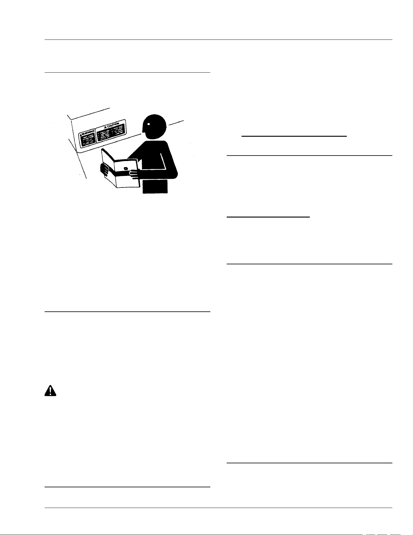
Using Your Operator’s Manual
Read this operator’s manual, watch the safety video,
www.deere.com/QR and review the safety signs on your
machine before use. They all contain important safety
information and operating instructions that must be
followed to help keep you and others safe. Be sure
everyone who uses the machine has read the manual,
reviewed the safety signs, and knows how to use the
machine safely and properly.
Your machine was designed and built to be operated in
accordance with all the safe operating instructions.
Since it was designed to cut grass, it can amputate
hands and feet and throw objects. If you do not follow
safety instructions, serious injury or death can occur.
This operator manual is organized in sections to help
you nd information quickly. You can use this manual to
nd answers to many of your operating and servicing
questions. An index at the end of this book helps you
nd needed information quickly. Contact your dealer if
this manual does not answer your questions.
Before using your machine:
● Know how to operate the machine. The Operating
Controls section helps you understand the controls of
your machine and what they do.
● Prepare your machine and the mowing area by
performing required daily checks outlined in the
General Instructions section.
● Follow instructions in the Preventing Injuries section,
especially related to:
- Keeping children safe by following instructions in
the Protect Children section.
- Avoiding injury on slopes and near terrain
hazards by following instructions in the Operating
on Slopes and Near Terrain Hazards section.
- Follow the instructions in the Avoid Thrown
Objects section and keep all guards in place,
including discharge chute.
- Cleaning machine during use and before storing
as outlined in the Prevent Fires section.
● Understand how to service and inspect your
machine.
If you do not understand the instructions or have
questions, contact your dealer.
The machine shown in this manual can dier slightly
from your machine.
RIGHT-HAND and LEFT-HAND sides are determined
by facing in the direction that the machine travels when
going forward. When you see a broken line (------), the
item referenced is hidden from view.
Before delivering this machine, your dealer performed a
predelivery inspection to ensure best performance.
Introduction
This manual is an important part of your machine. Keep
this manual with the machine when you sell it.
mk71445,1654877011782-19-10JUN25
John Deere Is at Your Service
TS201—UN—15APR13
Customer satisfaction is important to John Deere.
Our dealers strive to provide you with prompt, ecient
parts, and service:
• Maintenance and service parts to support your
equipment.
• Trained service technicians and the necessary
diagnostic and repair tools to service your equipment.
• John Deere replacement parts, repair services,
and information for maintenance or repair are
available. For more information, please visit deere.
com or deere.ca.
DX,IFC,JDS-19-30SEP25
Special Messages
Your manual contains special messages to bring
attention to potential safety concerns and machine
damage, as well as helpful operating and servicing
information. Please read all the information carefully to
avoid injury and machine damage.
CAUTION: Avoid injury! This symbol and text
highlight potential hazards or death to the
operator or bystanders that may occur if the
hazards or procedures are ignored.
IMPORTANT: Avoid damage! This text is used to tell
the operator of actions or conditions that might
result in damage to the machine.
NOTE: General information is given throughout the
manual that may help the operator in the operation
or service of the machine.
MX00654,000020D-19-04AUG25
Parts
We recommend John Deere quality parts and
lubricants, available at your John Deere dealer.
When you order parts, your John Deere dealer needs
the serial number or product identication number (PIN)
for your machine or attachment. These are the numbers
that you recorded in the Product Identication section of
this manual.
Order Service Parts Online
Visit https://partscatalog.deere.com/jdrc/ for your
Internet connection to parts ordering and information.
TC00531,00000E9-19-04AUG25
Service Literature
If you would like to purchase a copy of the Parts Catalog
or Technical Manual for this machine, visit The John
Deere Technical Information Store at:
https://techpubs.deere.com/
or call:
● U.S. & Canada: 1-800-522-7448.
● All Other Regions: Your John Deere dealer.
TH84124,0000199-19-04AUG25
Spark Arrestor
The California Public Resources Code, Section 4442.5
provides as follows:
No person shall sell, oer for sale, lease, or rent to any
person any internal combustion engine subject to
Section 4442 or 4443, and not subject to Section 13005
of the Health and Safety Code, unless the person
provides a written notice to the purchaser or bailee, at
the time of sale or at the time of entering into the lease
or rental contract, stating that it is a violation of Section
4442 or 4443 to use or operate the engine on any forest-
covered, brush-covered, or grass-covered land unless
the engine is equipped with a spark arrestor, as dened
in Section 4442, maintained in eective working order or
the engine is constructed, equipped, and maintained for
the prevention of re pursuant to Section 4443. Cal.
Pub. Res. Code 4442.5. Other states or jurisdictions
may have similar laws. A spark arrestor for your
machine may be available from your John Deere dealer
or other servicing provider. An installed spark arrestor
must be maintained in good working order by the
operator.
OUO2005,00006F6-19-17OCT25
Introduction

Trademarks
Trademarks
CargO Mount™ Trademark of Deere & Company
Deere Trademark of Deere & Company
Plus-50 Trademark of Deere & Company
John Deere Trademark of Deere & Company
Turf-Gard Trademark of Deere & Company
John Deere Easy Change™ Trademark of Deere & Company
MowerPlus™ Trademark of Deere & Company
Plus-4™ Trademark of Deere & Company
Grease-Gard™ Trademark of Deere & Company
SDHTXN6,1748839051116-19-01JUN25
Introduction

Page
Product Identication
Record Identication Numbers ....... . . ......... . ... 00-1
Register Your Product and Warranty Online . ...... 00-1
Safety Labels with Text
Safety Label Location . . . ......... . . ......... . . ........ 05-1
Understanding the Machine Safety Labels . . . ...... 05-2
DANGER ......... . . .......... ........... .......... . .... 05-2
DANGER ......... . . .......... ........... .......... . .... 05-2
DANGER ......... . . .......... ........... .......... . .... 05-2
WARNING ........ . . .......... ........... ........... .... 05-3
CAUTION ........ ........... ........... . ......... . . .... 05-3
Avoid Injury From Hot Surface ... ........... ........ 05-3
CAUTION ........ ........... ........... . ......... . . .... 05-4
Safety Labels without Text
Safety Label Location . . . ......... . . ......... . . ........ 06-1
Understanding the Machine Safety Labels
without Text ... . . .......... . .......... . .......... . ... 06-2
Read Operator’s Manual ...... . . .......... ........... 06-2
Keep Children Away from Mower ......... . . ........ 06-2
Avoid Serious Injury or Death from Tipping .. . ..... 06-2
Avoid Injury from Getting Caught in Belts ........ .. 06-2
Avoid Injury from Equipment Fires . ........... ...... 06-3
Avoid Injury from Rotating Blades ... . . ......... . . .. 06-3
Avoid Injury from Hot Surfaces ......... ........... .. 06-3
Avoid Injury from Rotating Blades and
Thrown Objects ........ . .......... ........... ...... 06-3
Safety
Use Your Mower Safely ........... ........... ........ 10-1
Preventing Injuries ........ . .......... . . ......... . . .... 10-2
Operating on Slopes and Near Terrain
Hazards ......... . . ......... . . .......... ........... .. 10-2
Prevent Fires . . .......... . .......... ........... ........ 10-3
Parking Safely .......... . .......... . ......... . . ........ 10-4
Additional Safety Information . .......... . .......... . . 10-4
Machine Cleanout
General Cleaning Guidelines . .......... . .......... . . 15-1
Cleanout Areas . . .......... . .......... ........... ...... 15-1
Operating Controls
Operator’s Station Controls . .......... . . ......... . . .. 25-1
Operating
Daily Operating Checklist ... ........... . ......... . . .. 30-1
Adjusting Seat ......... . . ......... . . ......... . . ........ 30-1
Adjusting Cutting Height . . ......... . . ......... . . ...... 30-1
Checking and Adjusting Mower Deck Level ..... .. 30-1
Adjusting Mower Deck Wheels ... . .......... ........ 30-4
Page
Testing Safety Systems ...... . . .......... . .......... . 30-4
Testing Park Brake Switch . .......... . .......... ..... 30-5
Testing Park Brake . ......... . . .......... . .......... ... 30-5
Testing Attachment Engagement Switch or
Lever .. ........... .......... . .......... . .......... . . . 30-5
Testing Seat Switch ........ . .......... ........... ..... 30-5
Testing Reverse Implement Option (RIO) . . ........ 30-5
Using the Park Brake ....... . . .......... . .......... . .. 30-6
Checking Fuel Level (If Equipped) ......... . . ....... 30-6
Using Hourmeter and MowerPlus™ Fuel
Gauge (If Equipped) .. . .......... . . ......... . . ..... 30-6
Using Key Switch and Headlights ................. . . 30-7
Starting the Engine .... . . ......... . .......... ......... 30-7
Idling the Engine ............ .......... . . ......... . . ... 30-7
Stopping the Engine .......... .......... . .......... . . . 30-8
Using Travel Controls on Hydrostatic
Transmission .. .......... . .......... . . ......... . . ... 30-8
Using The Reverse Implement Option (RIO) ...... 30-9
Using Cruise Control (If Equipped) ........ . . ....... 30-9
Engaging and Disengaging Mower ...... . . ......... 30-9
Using Wash Port to Clean Mower Deck . .......... 30-10
Unplugging Mower, Bagger, or Material
Collection System ........ .......... . . ......... . . .. 30-10
Moving Machine by Hand .... . ..................... . 30-10
Transporting Machine on Trailer . ........... ........ 30-11
Transporting Material Collection System (If
Equipped) ..... . .......... . .......... . . ......... . . .. 30-12
Using Weights .......... ........... ........... ........ 30-12
Using Tire Chains .......... . .......... . . ......... . ... 30-12
Using Accessories ......... . .......... . .......... .... 30-12
Choosing Mower Blades ..... .......... . .......... . . 30-13
Mowing Tips . ......... . .......... ........... .......... 30-13
Towing Loads . .......... . . ......... . . ......... . . ...... 30-13
Service Intervals
Servicing Your Machine .... . . .......... . .......... . .. 35-1
Service Intervals ....... . .......... . ......... . . ......... 35-1
Service Lubrication
Grease ........ . .......... . .......... ........... ......... 40-1
Lubricating Front Axle . . .......... ........... ......... 40-1
Lubricating Pivot Points ...... . . .......... . .......... . 40-1
Service Engine
Emissions Service Information ...... . . ......... . . ... 45-1
Avoid Fumes ...... ........... .......... . . ......... . . ... 45-1
Gasoline Engine Oil . .......... ........... .......... . . . 45-1
Checking Engine Oil Level . . . .......... . .......... ... 45-2
Changing John Deere Easy Change™ 30-
Second Oil Change System (If Equipped) ...... 45-2
Continued on next page
Original Instructions. All information, illustrations and specications in this
manual are based on the latest information available at the time of publication.
The right is reserved to make changes at any time without notice.
COPYRIGHT © 2025
DEERE & COMPANY
Moline, Illinois
All rights reserved.
Previous Editions
Copyright © 2020, 2021, 2022, 2023, 2024
Contents
i

Page
Changing Engine Oil and Filter on models not
equipped with the John Deere Easy
Change™ 30-Second Oil Change System ...... 45-3
Cleaning Air Intake Screen and Engine Fins ...... 45-4
Checking and Cleaning Air Cleaner Elements .... 45-4
Checking Spark Plug ... .......... . ......... . . ........ 45-6
Replacing Fuel Filter .... . . ......... . .......... ........ 45-6
Spark Arrestor Maintenance (If Equipped) ....... . . 45-7
Service Transmission
Checking Transmission ..... . .......... . . ......... . . .. 50-1
Service Mower
Removing or Installing Mower Drive Belt at
Engine Drive Sheave in Manual PTO
Machines ...... . . .......... . .......... ........... .... 55-1
Removing or Installing Mower Drive Belt at
Engine Drive Sheave in Electronic PTO
Machines ...... . . .......... . .......... ........... .... 55-1
Removing Mower Deck ..... . .......... . .......... . ... 55-1
Installing Mower Deck ...... . .......... . . ......... . ... 55-3
Replacing Mower Drive Belt—42 in Deck . . ........ 55-3
Replacing Mower Drive Belt—48 in and 54 in
Decks . . . ......... . . ......... . ........... ........... .. 55-4
Checking for Bent Mower Blades ................... 55-4
Servicing Mower Blades .. . .......... . .......... ...... 55-5
Sharpen Blades ... . .......... . ........... .......... . .. 55-5
Balance Blades .... . . ......... . . .......... . .......... .. 55-6
Service Electrical
Electrical . ......... . . .......... ........... ........... .... 60-1
Service the Battery Safely ........ .......... . ........ 60-1
Removing and Installing the Battery . . . ......... . . .. 60-1
Clean Battery and Terminals ............ .......... . .. 60-2
Use Booster Battery ..... . ......... . . ......... . . ...... 60-2
Replacing Headlight .. ........... .......... . .......... 60-2
Replacing Fuse ..... . ......... . . .......... . .......... . . 60-3
Service Miscellaneous
Gasoline Fuel for 4-Cycle Engines .......... ........ 65-1
Fill Fuel Tank ... . .......... . .......... . . ......... . . .... 65-1
Lifting Machine ...... . .......... . ..................... . 65-1
Checking Tire Pressure .. . .......... . . ......... . ..... 65-2
Removing and Installing Hood ........ . . ......... . ... 65-2
Cleaning Plastic Surfaces ........ . ......... . . ........ 65-3
Cleaning and Repairing Metal Surfaces .......... . . 65-3
Avoid Damage to Plastic and Painted
Surfaces .... . .......... . . ......... . .......... ........ 65-3
Removing and Installing Front Wheel
Assembly . . .......... . .......... . .......... .......... 65-4
Removing and Installing Rear Wheel
Assembly . . .......... . .......... . .......... .......... 65-4
Troubleshooting
Using Troubleshoot Chart . .......... . . ......... . . .... 70-1
Engine ..... . . ......... . . ......... . . .......... ........... 70-1
Electrical . ......... . . .......... ........... ........... .... 70-1
Tractor .. . ......... . . .......... . .......... . . ......... . ... 70-2
Mower ..... . .......... ........... .......... . .......... . . 70-2
Storage
Storing Safety ....... .......... . .......... . .......... . . 75-1
Preparing Machine for Storage ....... ........... .... 75-1
Page
Preparing Fuel and Engine For Storage ...... . . ... 75-1
Removing Machine From Storage .... . .......... . .. 75-2
Specications
Model S100 .... . .......... ........... ........... ....... 80-1
Model S110 ..... . . .......... . .......... ........... ..... 80-1
Models S120, S130, S140, and S160 ......... ..... 80-1
Models S170 and S180 ........ ........... .......... . 80-1
Electrical System ...... . .......... . ......... . . ......... 80-1
Fuel System (All Models) .. .......... . . ......... . .... 80-1
Tires ... . ......... . . .......... . .......... . . ......... . .... 80-1
Capacities ...... . .......... . .......... ........... ....... 80-2
Dimensions ......... .......... . .......... . .......... . . . 80-2
Mower Deck - 107 cm (42 in) ..... .......... . ....... 80-2
Mower Deck - 122 cm (48 in) ..... .......... . ....... 80-2
Mower Deck - 137 cm (54 in) ..... .......... . ....... 80-2
Recommended Lubricants . .......... . . ......... . .... 80-2
Warranty
Product Warranty .... . ......... . . .......... . .......... . 85-1
U.S. EPA Emission Control System Warranty
Statement (O-Road Engine Equipment) .... . . . 85-1
Tire Warranty ....... ........... .......... . .......... . . . 85-3
Limited Battery Warranty For Factory
Installed Batteries ....... . .......... . . ......... . . ... 85-3
John Deere Quality Statement
John Deere Quality ....... .......... . . ......... . . . JDQS-1
Service Record
Record Service Dates . . . ......... . .......... ........ SR-1
Slope Gauge
Slope Gauge Template .... . .......... . . ......... . ... SG-1
Contents
ii
Record Identication Numbers
Lawn Tractors
S Series Riding Lawn Tractors.
When you contact an Authorized Service Center for
information on servicing, always provide the product
model and product identication numbers.
Locate the model, product identication number, and
engine serial number of your machine. Record the
information in the space provided as follows:
DATE OF PURCHASE:
_________________________________________
DEALER NAME:
_________________________________________
DEALER PHONE:
_________________________________________
PRODUCT IDENTIFICATION NUMBER:
__ __ __ __ __ __ __ __ __ __ __ __ __ __ __ __ __
ENGINE SERIAL NUMBER:
__ __ __ __ __ __ __ __ __ __ __ __ __ __ __ __ __
Machine Product Identication Number Location
APY33773—UN—06APR20
Left-Hand Side of the Machine Shown
Engine Serial Number Location
APY33771—UN—06APR20
V-Twin Cylinder Engine Model Shown
SDHTXN6,1745648864442-19-26APR25
Register Your Product and Warranty Online
To register your product through the Internet, simply go
to www.JohnDeereWarrantyRegistration.com.
Completing the information, either online or with the
product warranty card, will ensure that your product will
receive all post sales, service, and important product
information.
MP47322,00F45FF-19-17MAY22
Product Identication
00-1

Safety Label Location
MX663345—UN—06MAY25
A—WARNING— GX23479
B—DANGER/WARNING/CAUTION — UC43017
C—CAUTION— UC27081
D—DANGER — M139128
E—DANGER — M89504
F—DANGER — M118610
SDHTXN6,1745831068322-19-06MAY25
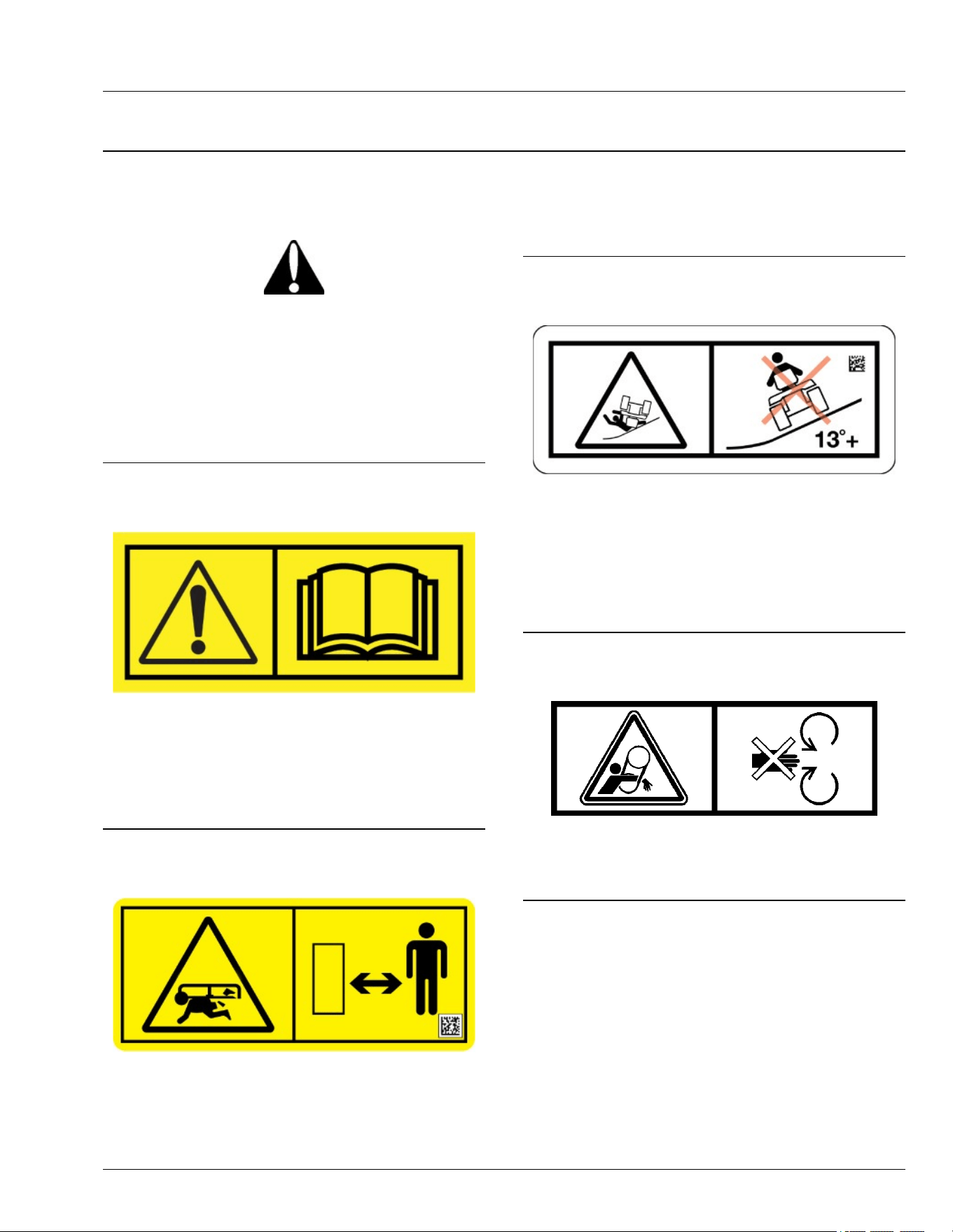
Safety Labels with Text
05-1
Understanding the Machine Safety Labels
MXAL42363—UN—22MAY13
The machine safety labels shown in this section are
placed in important areas on your machine to draw
attention to potential safety hazards. DANGER or
WARNING safety labels are located near specic
hazards.
The operator’s manual also explains any potential
safety hazards whenever necessary in special safety
messages that are identied with the word, CAUTION,
and the safety-alert symbol.
On your machine safety labels, the words DANGER,
WARNING, and CAUTION are used with this safety-
alert symbol. DANGER identies the most serious
hazards:
● DANGER; The signal word DANGER indicates a
hazardous situation which, if not avoided, will result
in death or serious injury.
● WARNING; The signal word WARNING indicates a
hazardous situation which, if not avoided, could
result in death or serious injury.
● CAUTION; The signal word CAUTION indicates a
hazardous situation which, if not avoided, could
result in minor or moderate injury. CAUTION may
also be used to alert against unsafe practices
associated with events which could lead to personal
injury.
Replace missing or damaged safety labels. Use this
operator’s manual for correct safety label placement.
There can be more safety information contained on
parts and components sourced from suppliers that is not
reproduced in this operator’s manual.
French or Spanish Safety Labels and Operator’s
Manual
Operator’s manuals and safety labels with content in
French or Spanish are available for this machine
through authorized John Deere dealers. See your John
Deere dealer.
NOTE: Both text and no-text labels are shown. Your
machine is only equipped with one of these types of
labels.
MP47322,00F4601-19-21FEB23
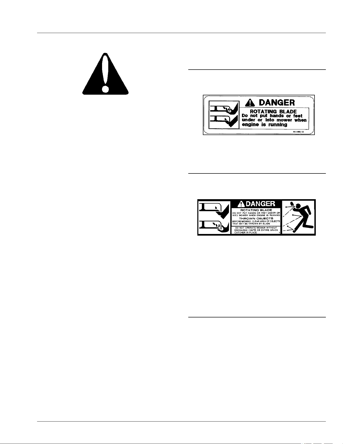
DANGER
GXAL41947—UN—04MAR13
ROTATING BLADE
● Do not put hands or feet under or into mower when
engine is running.
OUO2004,0000BAF-19-28FEB15
DANGER
GXAL41948—UN—04MAR13
ROTATING BLADE
● Do not put hands or feet under or into mower when
engine is running.
THROWN OBJECTS
● Before mowing, clear area of objects that may be
thrown by blade.
● Do not operate mower without discharge chute or
entire grass catcher in place.
OUO2004,0000BB0-19-28FEB15
DANGER
Safety Labels with Text
05-2
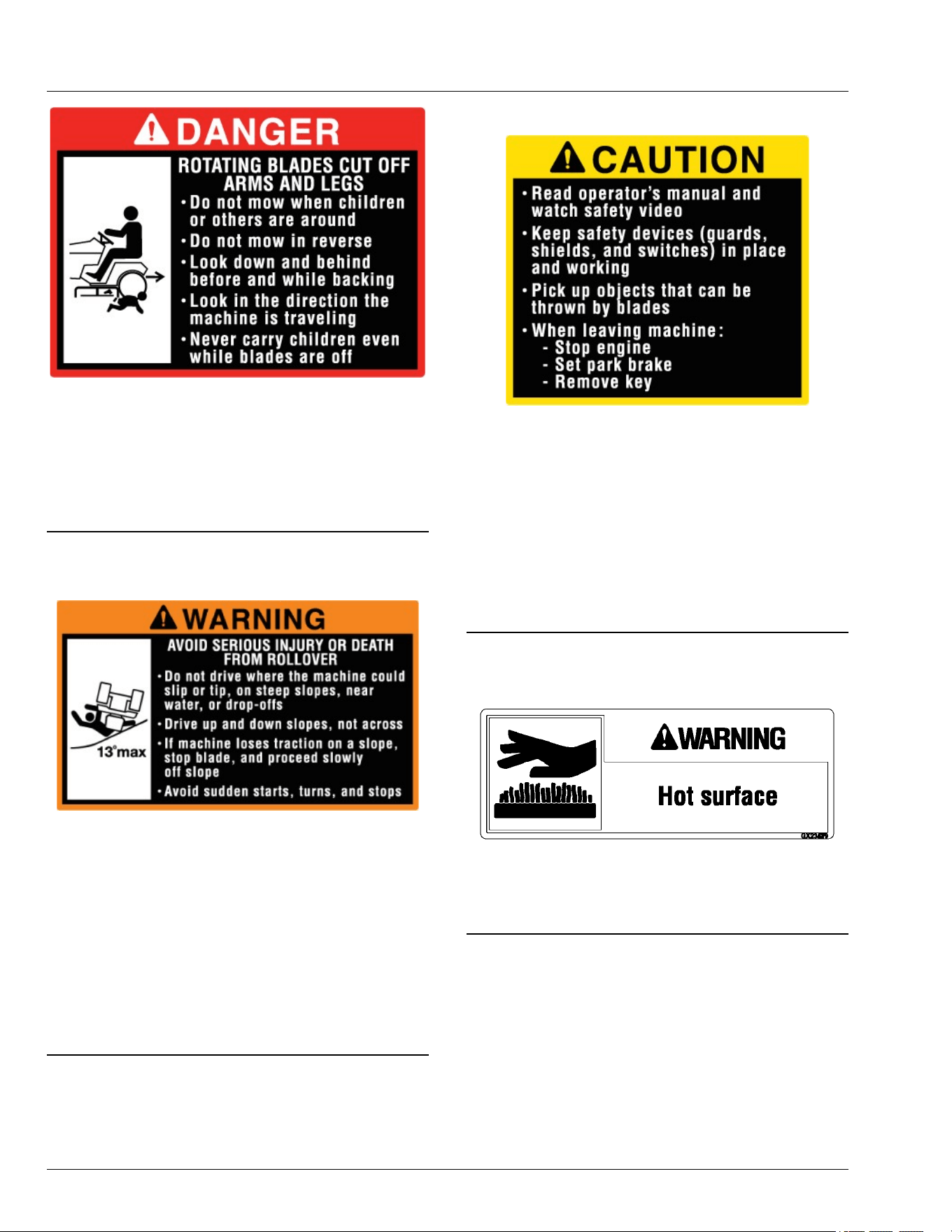
MX663346—UN—06MAY25
ROTATING BLADES CUT OFF ARMS AND LEGS
● Do not mow when children or others are around.
● Do not mow in reverse.
● Look down and behind before and while backing.
● Never carry children, even with the blades o.
SDHTXN6,1745831127013-19-06MAY25
WARNING
MX663347—UN—06MAY25
AVOID SERIOUS INJURY OR DEATH FROM
ROLLOVER
● Do not drive where the machine could slip or tip, such
as on steep slopes, near water, or drop-os.
● Drive up and down slopes, not across them.
● If the machine loses traction on a slope, stop the
blade, and proceed slowly o the slope.
● Avoid sudden starts, turns, and stops.
● Never mow or operate the machine on slope angles
greater than 13 degrees.
SDHTXN6,1745831186522-19-01JUN25
CAUTION
MX663348—UN—06MAY25
● Read the operator’s manual and watch the safety
video.
● Keep safety devices (guards, shields, and switches)
in place and working.
● Pick up objects that can be thrown by blades.
● When leaving the machine:
- Stop the engine
- Set the park brake
- Remove the key
SDHTXN6,1745831157966-19-06MAY25
Avoid Injury From Hot Surface
GXAL41952—UN—04MAR13
WARNING
● Hot surface
OUO2004,0000BB3-19-28FEB15
Safety Labels with Text
05-3

CAUTION
APY36145—UN—10JUL20
Avoid equipment res
Accumulation of grass, leaves and other debris on or
near hot or moving parts can cause a re
Inspect machine before, during, and after use
Shut o engine and allow machine to cool before
cleaning
MG39705,00004A7-19-26JUN20
Safety Labels with Text
05-4

Safety Label Location
MX663349—UN—06MAY25
A—Read OM, Keep Children Away from Mower; Avoid Injury from
Tipping — UC43019
B— Avoid Injury from Getting Caught in Belt – M136436
C— Avoid Injury from Equipment Fires — GX24503
D— Avoid Injury from Rotating Blades — M118041
E— Avoid Injury from Hot Surfaces — GX25568
F— Avoid Injury from Rotating Blades and Thrown Objects —
M148522
Safety Labels without Text
06-1
G— Avoid Injury from Rotating Blades and Thrown Objects —
M118040
SDHTXN6,1745840712744-19-06MAY25
Understanding the Machine Safety Labels
without Text
TCT005498—UN—11SEP12
The machine safety labels shown in this section are
placed in important areas on your machine to draw
attention to potential safety hazards.
On your machine safety labels, the words DANGER,
WARNING, and CAUTION are used with this safety-
alert symbol. DANGER identies the most serious
hazards.
MX00654,0000389-19-09JAN23
Read Operator’s Manual
MX682199—UN—31JUL25
● This operator’s manual contains important
information necessary for safe machine operation.
● Carefully read operator’s manual before operating
machine or attachment. Observe all safety rules to
avoid accidents.
MX00654,000038B-19-04AUG25
Keep Children Away from Mower
TC1362283—UN—28MAR24
● Mower can cause dismemberment or death.
● Stay a safe distance from the machine.
● Make sure that children stay clear of mower at all
times when the engine is running.
MX00654,000038D-19-08APR24
Avoid Serious Injury or Death from Tipping
GX669619—UN—02JUN25
● Do not drive where the machine could slip, tip, or roll
over.
● Never mow or operate the machine on slope angles
greater than 13 degrees.
● Refer to the "Operating on Slopes" section for more
information.
SDHTXN6,1745840798584-19-10JUN25
Avoid Injury from Getting Caught in Belts
MXT018017—UN—03MAY16
● Stay clear of moving belts.
● Do not operate machine without shields in place.
MX00654,0000391-19-24APR19
Safety Labels without Text
06-2
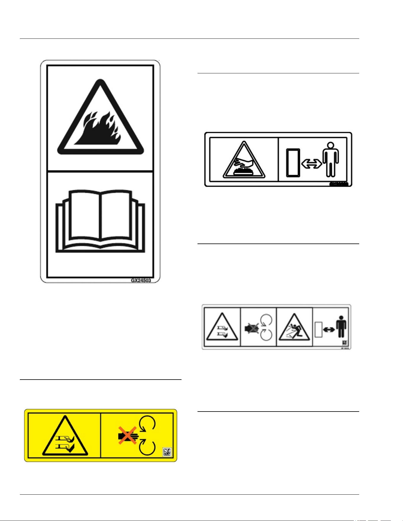
Avoid Injury from Equipment Fires
APY36195—UN—10JUL20
● Avoid equipment res.
● Accumulation of grass, leaves, and debris on or near
hot or moving parts can cause a re.
● Inspect and clean the entire machine before, during
and after use.
● Shut o engine and allow machine to cool before
cleaning.
● Carefully read operator’s manual Machine Cleanout
section for details.
MG39705,00004B6-19-06JUL20
Avoid Injury from Rotating Blades
TC1362285—UN—28MAR24
● Do not put hands or feet under or into mower when
engine is running.
● Do not operate mower without discharge chute/
deector or entire grass catcher in place.
MX00654,0000392-19-08APR24
Avoid Injury from Hot Surfaces
APY36196—UN—10JUL20
● Keep away from hot surfaces.
MG39705,00004B7-19-06JUL20
Avoid Injury from Rotating Blades and
Thrown Objects
APY36197—UN—10JUL20
Avoid injury from rotating blade and thrown objects. Do
not operate blower without entire grass catcher in place.
Shut engine o before unclogging or servicing.
MG39705,00004B8-19-06JUL20
Safety Labels without Text
06-3

Use Your Mower Safely
General Instructions
● Read this operator’s manual, watch the safety video,
and review the safety signs on your machine before
use. They all contain important safety information
and operating instructions that must be followed to
help keep you and others safe. Be sure everyone
who uses the machine has read the manual,
reviewed the safety signs, and knows how to use the
machine safely and properly.
● Never mow when there is a risk of lightning.
● Age, physical ability, and mental capacity can be
factors in equipment-related injuries. Operators must
be mentally and physically capable of operating the
machine properly and safely. Never allow a child to
operate the machine.
● Do not operate the machine while under the
inuence of alcohol or drugs or when distracted or
fatigued. Proper operation requires your full
attention.
● Always wear eye protection, hearing protection,
close-tting clothing, and substantial footwear while
operating the machine. Never operate while wearing
sandals or when barefoot.
● Do not wear radio or music headphones. Both safe
operation and service require your full attention.
● Never tamper with safety devices.
● Operate the machine only in daylight or good articial
light.
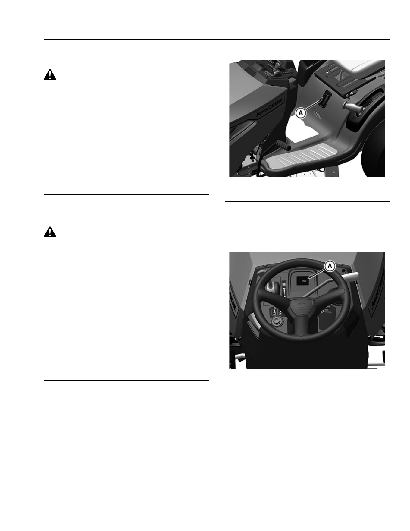
● Only operate the engine in well-ventilated areas.
Exhaust gasses contain carbon monoxide, a deadly
poison.
● Never leave a running machine unattended.
● Look both ways when approaching roadways and
use caution when turning around on public
roadways. You can be struck by a vehicle and suer
serious injury or death.
Before Using Your Machine
● Know how to operate the machine. The Operating
Controls section helps you understand the controls of
your machine and what they do.
● Prepare your machine and the mowing area by
performing required daily checks outlined in the
General Instructions section.
● Follow instructions in the Preventing Injuries section,
especially related to:
- Keeping children safe by following instructions in
the Protect Children section.
- Avoiding injury on slopes and near terrain
hazards by following instructions in the Operating
on Slopes and Near Terrain Hazards section.
- Follow the instructions in the Avoid Thrown
Objects section, and keep all guards in place,
including discharge chute.
- Cleaning machine during use and before storing
as outlined in the Prevent Fires section.
● Understand how to service and inspect your
machine.
Inspection and Daily Checklist
● Inspect machine before you operate. Be sure that
hardware is tight, and all guards and shields are in
good condition and fastened in place. Make all
necessary adjustments before you operate. Repair or
replace damaged, badly worn, or missing parts.
● Visually inspect that mower blades, blade bolts, and
the mower assembly are not worn or damaged. To
prevent machine damage, replace worn or damaged
blades and bolts in sets.
● Make sure that the fuel cap and air cleaner are in
place before starting engine.
Fuel
● Use care when handling fuel. Fuel is ammable and
fuel vapors can be explosive. Do not smoke when
handling fuel. Only use an approved fuel container.
Clean up spilled fuel immediately.
● Check fuel lines, tank, cap, and ttings frequently for
cracks or leaks. Replace if necessary.
Check the Mowing Area
● Keep bystanders and pets out of the mowing area.
● Clear the area of objects such as rocks, wire, or toys,
which can be thrown by the blades. Remove low-
hanging branches or other obstacles, which can
interfere with your travel path.
● Study the mowing area. Set up a safe mowing path.
Do not mow where traction or stability is doubtful.
● Slopes and terrain hazards are major factors related
to loss-of-control and tipover accidents. Operation on
slopes and near terrain hazards requires extra
caution. Follow instructions in the Operating on
Slopes and Near Terrain Hazards section.
Weights and Attachments
● Some attachments require ballast weights. Follow
recommendations for wheel weights or
counterweights.
● Use only accessories and attachments approved by
John Deere.
● If you do not understand the instructions or have
questions, contact your dealer or other service
provider.
SDHTXN6,1745840906380-19-29JUL25
Safety
10-1

Preventing Injuries
Protect Children
MXAL41929—UN—18FEB13
● Children can be killed or seriously injured by riding
mowers when operators do not follow safe operating
practices.
● Do not mow in reverse. Operating with the mower
engaged while backing up is discouraged.
● Never give children a ride on a mower or in a cart
behind the mower, even when the blades are o.
They can fall o and be run over or cut by the mower
blades. Children can interfere with mower operation.
Children who have been given rides in the past can
suddenly appear in the mowing area for another ride.
If you are not aware, they can be run over or backed
over by the mower.
● Children are often attracted to lawn mowers and
mowing activities, especially if they have been given
rides before. They do not know if the blades are
rotating or understand that they can be killed or
seriously injured even if the blades are not rotating.
● Keep children indoors and out of the mowing area
when the mower is being operated. Keep children
under the watchful eye of a responsible adult, other
than the operator. If there is not a responsible adult to
ensure that children stay indoors, DO NOT mow.
● Be alert to the presence of children or others. Turn o
the mower blades and stop the machine if someone
enters the mowing area.
● Look in the direction the machine is traveling. Before
and while backing, turn o the mower blades and
look down and behind the machine carefully,
especially for children.
● Use extreme care when approaching objects that
block your view, such as blind corners, shrubs, or
trees, especially while backing. They can hide a
child.
Avoid Thrown Objects
● Clear the mowing area of all bystanders when using
this machine. Thrown objects could cause serious
injury or death.
● Clear the area of objects such as rocks, wire, or toys,
which can be thrown by the blades.
● Never direct discharged material toward anyone.
● Avoid discharging material against a wall or
obstruction such as a fence or retaining wall. Material
can ricochet towards the operator.
● Avoid discharging material towards a street or
roadway.
● Stop the blades when crossing gravel surfaces.
OUO2005,0000783-19-15FEB20
Operating on Slopes and Near Terrain
Hazards
● Slopes are a major factor related to loss of control
and tip-over accidents, which can result in serious
injury or death. Use caution and common sense
when operating on slopes.
● If you feel uneasy on a slope, do not mow or operate
the machine on it.
● Drive up and down slopes, not across them.
● Watch for holes, ruts, bumps, rocks, or other hidden
objects. Tall grass can hide obstacles.
● Drive slowly so you do not have to stop while on a
slope.
● Do not mow on wet grass. Tires can slip on wet grass
even if the brakes are working normally.
● Keep all movement on slopes slow and gradual. Do
not make sudden changes in speed or direction,
which can cause the ride-on mower to roll over.
● If the tires lose traction, disengage the PTO and
proceed slowly and carefully o the slope.
● Do not shift to neutral and coast downhill.
Identify Safe Slopes
● Before using your machine, measure the slopes of all
mowing areas to determine which slopes are safe for
mowing with a ride-on mower. Use good judgment
and common sense when performing this survey.
Measuring Slopes
● Suggested method 1: Lay a straight piece of sturdy
lumber 1.2 m (4 ft) long on the slope and measure
the angle with an angle gauge or protractor level.
● Suggested method 2: Refer to the slope gauge
provided at the end of the manual.
Slope Limits
● Exceeding the recommended maximum slope angle
increases the risk of rollover accidents that can result
in serious injury or death.
Safety
10-2
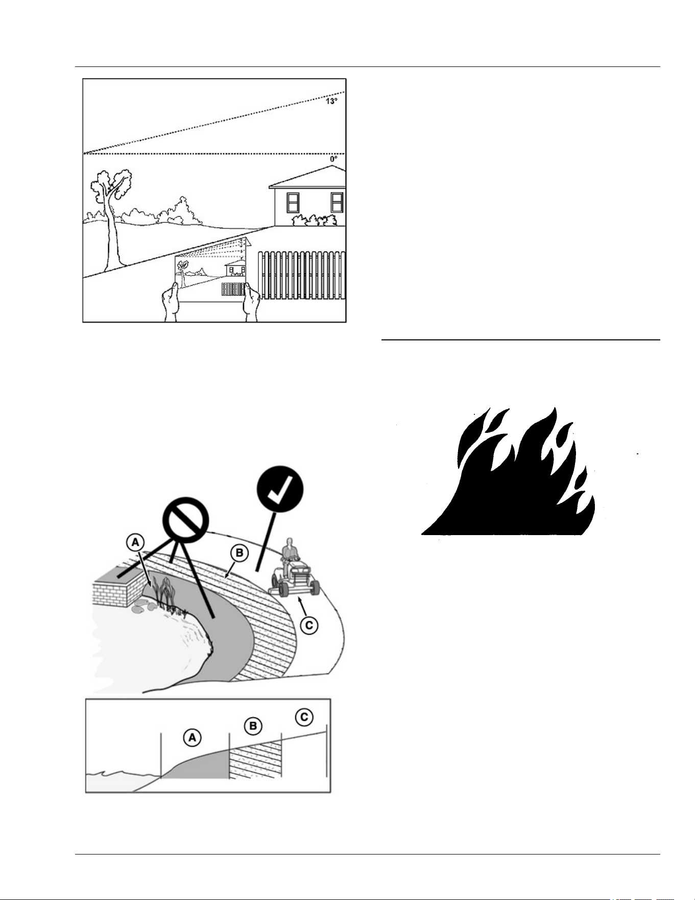
GX100108—UN—14FEB20
● Never mow or operate this ride-on mower on slope
angles greater than 13°. (A 13° slope is a slope that
rises 1.4 m [4.6 ft] over a horizontal distance of 6.1 m
[20 ft].)
● Material collection systems, weather enclosures, or
other attachments increase the risk of a rollover.
● As slope increases the risk of rollover increases.
Operating Near Terrain Hazards
GX100106—UN—01FEB20
● Terrain hazards such as ditches and drop-os are a
factor related to loss of control and tip-over
accidents, which can result in serious injury or death.
Use caution and common sense when operating
near terrain hazards.
● Do not mow or operate the machine in areas
adjacent to hazards that can cause the machine to
roll over. If a wheel goes over an edge or if the edge
breaks away, the machine can suddenly lose
traction, slide, and/or roll over.
● Hazards (A) include but are not limited to ditches,
drop-os, embankments, or areas near bodies of
water.
● Maintain a buer area (B) at least as wide as the
machine between hazards (A) and the mowing area
(C). Do not mow or operate the machine in the
hazard area or buer area.
● Only mow or operate in the mowing area (C). Do not
exceed the recommended slope operating angle.
Refer to the Slope Limits section.
SDHTXN6,1745840980137-19-04JUN25
Prevent Fires
TS227—UN—15APR13
● Do not mow tall, dry grass or through piles of leaves.
Combustible materials can contact hot components
and increase the risk of re.
● Debris can build up anywhere on the machine,
especially on horizontal surfaces. While using your
machine, periodically check for and remove debris,
especially in dry or heavy debris conditions, such as
when collecting leaves.
● After operating, completely remove any combustible
materials from equipment before storing. Use
compressed air, a leaf blower, or water to keep the
machine clean.
● Allow machine to cool in an open area before storing.
Do not park machine near ammable materials, such
as straw, mulch, cloth, or chemicals. Do not park
near an open ame or other sources of ignition, such
as a water heater or furnace.
● Excess lubrication or fuel/oil leaks or spills on the
machine can also provide collection sites for debris.
Promptly cleaning up spills and repairing leaks
reduces the potential for debris collection.
Safety
10-3

● Refer to the Machine Cleanout section for more
information on checking for debris buildup and
locations to inspect.
● Always park the machine safely before cleaning or
servicing a machine. See the Parking Safely section.
OUO2005,0000787-19-15FEB20
Parking Safely
Always apply the park brake and remove the key or key
pin before leaving the machine unattended. Children or
others may attempt to move or operate an unattended
machine.
● Bring the machine to stop on a level surface.
● Disengage mower blades or other attachments.
● Lower attachments to the ground.
● Apply the park brake.
● Shut the machine OFF.
● Remove the key or key pin.
● Wait for all moving parts to stop before you leave the
seat.
● Disconnect battery before maintenance.
OUO2005,0000788-19-12APR23
Additional Safety Information
Towing Loads Safely
● Stopping distance increases with speed and weight
of towed load. Travel slowly and allow extra time and
distance to stop.
● Total towed weight must not exceed Towing Capacity
stated in Specications of this manual.
● Excessive towed load can cause loss of traction and
loss of control on slopes. Reduce towed weight when
operating on slopes.
● Never allow children or others in or on towed
equipment.
● Use only approved hitches. Tow only with a machine
that has a hitch designed for towing. Do not attach
towed equipment except at the approved hitch point.
● Towed equipment increases the risk of rollover on
slopes. Refer to the Operating on Slopes and Near
Terrain Hazards section for more information.
● Do not turn sharply. Use additional caution when
turning or operating on adverse surface conditions.
Use care when reversing.
Safe Transportation
Follow instructions in the Transporting Machine on
Trailer section.
● Use a full-width loading ramp at least 30 cm (12 in)
wider than the machine, never two separate ramps.
Service and Maintenance
● Proper service and maintenance of the machine is
essential.
● Keep all parts in good condition, keep all nuts and
bolts tight, and repair any damage immediately. Stop
and inspect the machine immediately if you strike an
object.
● Ensure that all safety devices, discharge chute, and
grass catcher components are in good condition and
replace when necessary.
● Understand service procedures thoroughly before
working on the machine. If you do not understand the
service procedures or are uncomfortable working in
your machine, contact your John Deere dealer or
other service provider.
● Disconnect the battery or all spark plug wires before
servicing the machine. Disconnect negative terminal
rst and positive last. Install positive terminal rst and
negative last.
● Some components could have stored energy in
springs or hydraulic components. Servicing
procedures described in the Service section describe
how to perform service and maintenance tasks
safely.
● Support any machine elements that must be raised
for service work. Use jack stands or service locks to
support components when needed.
Disposing of Waste Products and Chemicals
● Waste products, such as used oil, fuel, coolant, brake
uid, and batteries can harm the environment and
people.
● Do not use beverage containers for waste uids –
someone can mistakenly drink from them.
● A Safety Data Sheet (SDS) provides specic details
on chemical products: Physical and health hazards,
safety procedures, and emergency response
techniques. The seller of the chemical products used
with your machine is responsible for providing the
SDS for that product.
● To learn how to recycle or properly dispose of waste
products generated from service, see your local
recycling center, John Deere dealer, or other service
provider. If you wish to discard the machine, contact
your local recycling center, John Deere dealer, or
other service provider.
OUO2005,0000789-19-17OCT25
Safety
10-4
General Cleaning Guidelines
Machine must be inspected periodically throughout the
day. Buildup of debris must be removed to ensure
proper machine function and to reduce the risk of re.
Frequency of these inspections and cleanings vary
depending on a number of factors including operating
conditions, machine conguration, operating speeds,
and weather conditions. Inspections and cleanings may
be required multiple times throughout the day
particularly in dry, hot, and windy conditions.
IMPORTANT: Avoid damage! Regular and thorough
cleaning of machine combined with other
routine maintenance procedures listed in the
Operator’s Manual greatly reduce the risk of
re, downtime, and improve machine
performance.
Besides proper maintenance, the condition of
the material being handled is the most
signicant factor contributing to res. Dry,
light, and uy materials that can create a dust
cloud are the most likely to catch re. Debris
can accumulate in various areas especially on
horizontal surfaces. Conditions such as wind
speed and direction can change where the
material accumulates. Be aware of these
changing conditions and adjust your cleaning
schedule and practices to ensure proper
machine function and to reduce the risk of re.
Always follow all safety procedures posted on the
machine and in the Operator’s Manual. Before carrying
out any inspection or cleaning, always shut OFF engine,
set park brake, and remove key.
The entire machine should be inspected, with extra
attention given to the areas noted below.
SR99263,000028F-19-15APR20
Cleanout Areas
Primary areas that must be inspected and cleaned on
the machine include (see Safety Label section):
APY33760—UN—26MAR20
APY33761—UN—26MAR20
1. Exhaust manifold (A), muer pipe (B), muer (C),
and muer shield (D).
APY36199—UN—28JUL20
2. Engine intake screens (E), cooling ns (F), and oil
cooler (if equipped).
Machine Cleanout
15-1
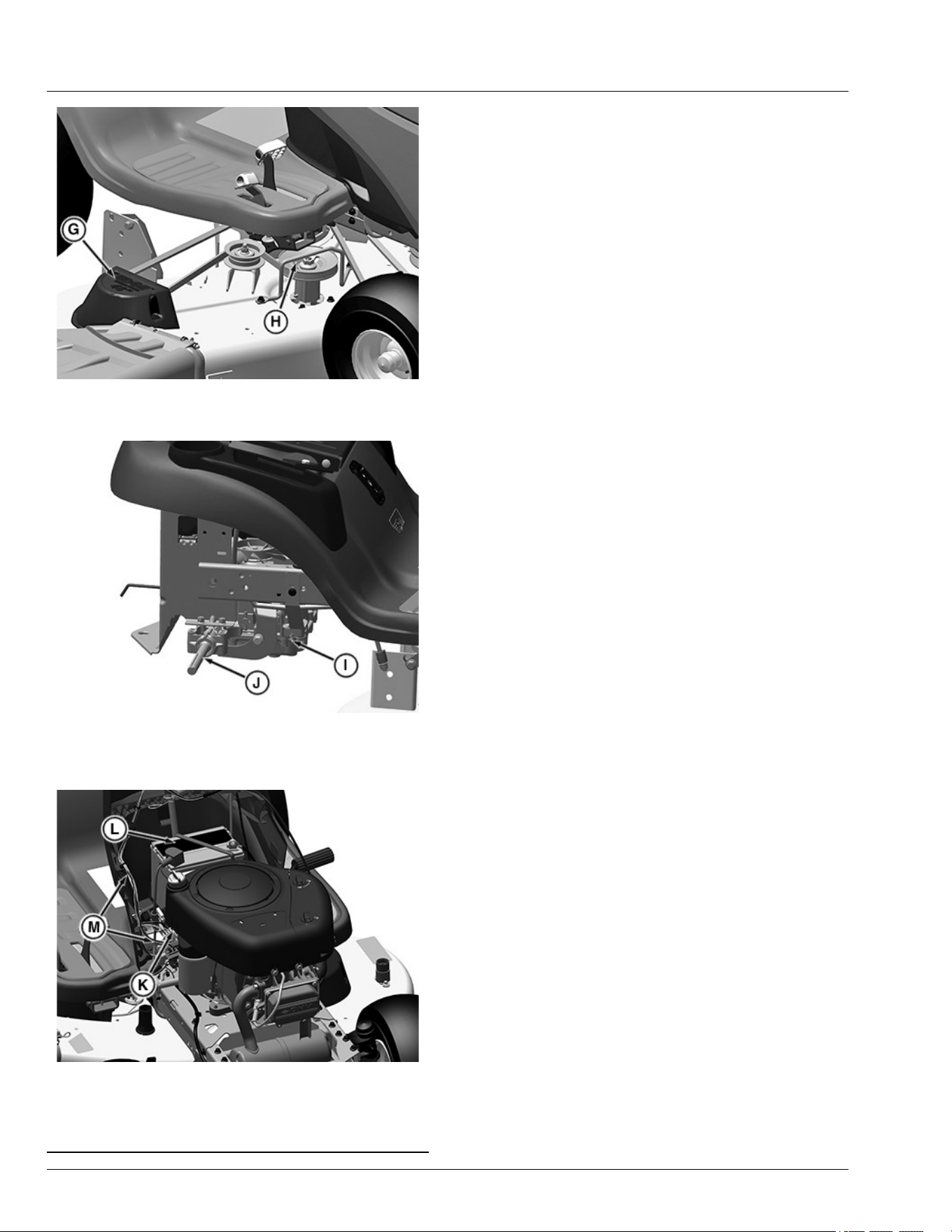
PY43269—UN—29MAY17
3. Top of mower deck, under shields (G), including
spindle (H) and belt areas.
APY36511—UN—14MAY20
Shown with Wheel Removed
4. On or near transmission (I) and driveline (J).
APY36151—UN—08APR21
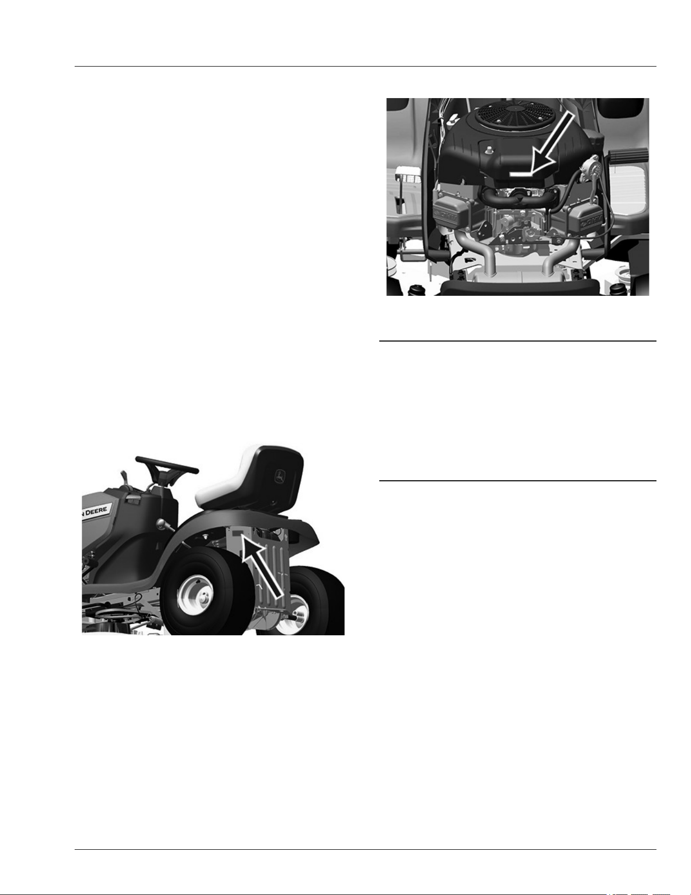
5. Under left side panel near fuse block (K) and all
wiring, including the battery (L) and related wiring
harnesses (M).
SR99263,00002FA-19-28JUL20
Machine Cleanout
15-2
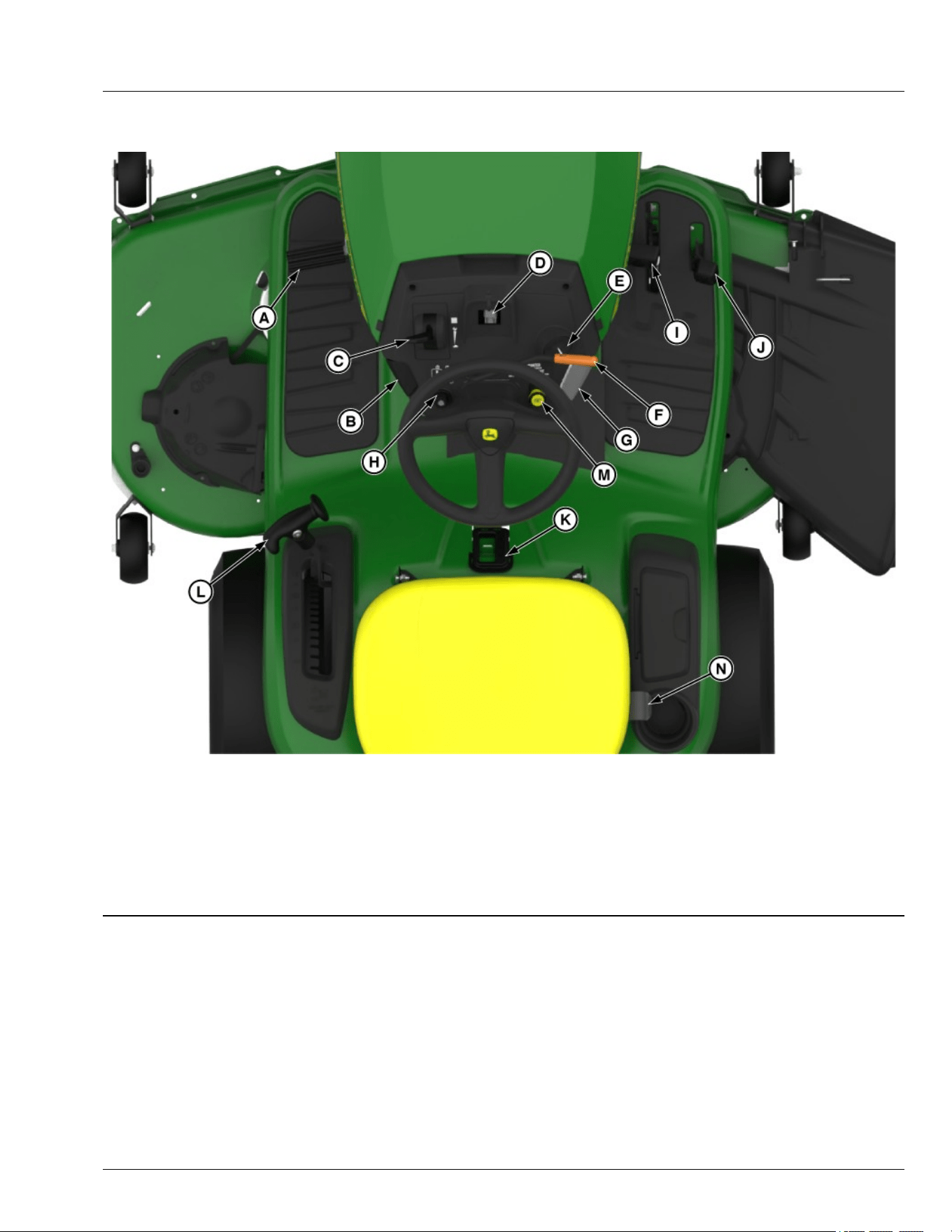
Operator’s Station Controls
GX663369—UN—22MAY25
.
A—Brake Pedal
B—Park Brake Lock Lever
C—Throttle/Choke Lever
D—Hourmeter/MowerPlus Fuel Gauge (if equipped)
E—Key Switch
F—Attachment Engagement Lever, Manual PTO (if equipped)
G—Cruise Control Lever (if equipped)
H—Reverse Implement Option (RIO) Switch
I—Forward Travel Pedal
J—Reverse Travel Pedal
K—Cover/Fuel Level Window (if equipped)
L—Attachment Lift Lever
M—Attachment Engagement Switch, Electric PTO (if equipped)
N—Seat Adjust Lever
SDHTXN6,1745841319178-19-22MAY25
Operating Controls
25-1
Daily Operating Checklist
Check/test safety systems.
Check tire pressure and brakes.
IMPORTANT: Avoid damage! Using stale,
contaminated, or improper fuel can result in
engine and fuel system damage. Repairs
caused by stale, contaminated, or improper fuel
are not covered by warranty.
Check fuel level. (See Service Miscellaneous
section, using proper fuel and stabilizer.)
Check engine oil level.
Remove grass and debris from engine compartment
and muer area, and on top of mower deck, before
and after operating machine.
Clean air intake screen.
Check below machine for uid leaks.
Check/tighten any loose hardware.
SR99263,0000293-19-15APR20
Adjusting Seat
1. Sit on seat.
APY34607—UN—31MAR20
2. Lift up on adjustment lever (A) on right side of seat.
3. Lean forward and slide seat forward or rearward to
desired position. Do not lean back on top of seat to
push rearward.
4. Release seat adjustment lever to lock in position.
SR99263,0000306-19-01APR20
Adjusting Cutting Height
Cutting height is adjusted from approximately 25—100
mm (1—4 in) in 6.4 mm (1/4 in) increments. When
mower deck is in the transport position, cutting height is
approximately 100 mm (4 in).
Detents allow the adjustment lever to be positioned at
each indicated mower setting, as well as the mid-point
between each setting.
Mower Setting Approximate Cutting Height
1 25 mm (1 in)
– 32 mm (1-1/4 in)
– 38 mm (1-1/2 in)
– 44 mm (1-3/4 in)
2 50 mm (2 in)
– 57 mm (2-1/4 in)
– 65 mm (2-1/2 in)
– 70 mm (2-3/4 in)
3 75 mm (3 in)
– 83 mm (3-1/4 in)
– 90 mm (3-1/2 in)
– 95 mm (3-3/4 in)
4 (Transport) 100 mm (4 in)
1. Put the attachment lift lever into the slot near desired
cutting height.
2. Adjust mower deck wheels.
Transporting or Getting on and o Machine
● Pull the attachment lift lever all the way back to
transport position or 100 mm (4 in) cutting height.
JS86122,00003BF-19-07MAY21
Checking and Adjusting Mower Deck Level
CAUTION: Avoid injury! Rotating blades are
dangerous. Before adjusting or servicing
mower:
● Disconnect spark plug wires or battery
negative (-) cable to prevent engine from
starting accidentally.
● Always wear gloves when handling mower
blades or working near blades.
NOTE: Mower deck wheels should not contact the
ground when leveling the mower deck.
Method One
1. Make sure machine is on a at, level surface.
2. Park machine safely. (See Parking Safely in the
Safety section.)
3. Check that tires are inated to correct tire pressure.
Tire pressure is marked on the side of the tire.
4. Raise deck to highest position.
Operating
30-1

APY18570—UN—10JUL20
42 in (107 cm) Mower Deck is Shown.
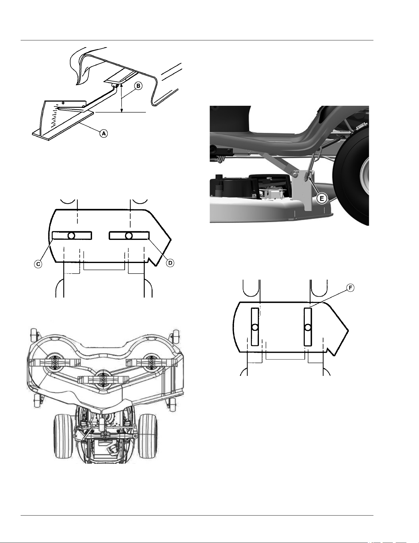
5. Place three short 51 mm (2 in) blocks of wood under
the edges (A) of the mower deck.
6. Lower mower deck to the 63 mm (2.5 in) cutting
height position.
For S130 models, lower deck to 57 mm (2-1/4 in)
cutting height position.
7. Check that the mower deck is level and lightly
touching each of the three wooden blocks.
APY36153—UN—24JUL20
● If the rear of the mower deck is not touching the
rear blocks, or is sitting heavily on the blocks,
adjust the rear lift links by turning the leveling nut
(B) on each lift link. The blocks should be able to
easily slide in and out beneath the mower deck
when the mower deck is correctly adjusted.
APY36154—UN—10JUL20
42 in (107 cm) Mower Deck is Shown.
● If the front of the mower deck is not lightly
touching the front block, adjust the front draft arm
by turning the nut (C).
8. Raise the cutting height to the next highest position
and remove the three wooden blocks.
9. Turn the nut (C) on the front draft arm
counterclockwise 1-2 full turns so that the front of the
deck is 3-6 mm (1/8-1/4 in) lower than the rear. This
adjustment prevents “double cutting,” which wastes
horsepower and causes brown grass tips.
Specication
Mower Deck, Front-to-
Back—Height. . . . . . . . . . . . . . . . . . . . . . . . . . 1/8-1/4 in (3-6 mm)
Method Two
NOTE: An optional mower deck leveling gauge
(AM130907) is available for purchase. It allows for
precision mower deck leveling by measuring
mower deck level at the blade tips.
1. Make sure that machine is on a at, level surface.
2. Park machine safely. (See Parking Safely in the
Safety section.)
3. Inate tires to the correct pressure.
4. Move mower lift handle to preferred cutting height.
5. Measure mower deck level (side-to-side).
Operating
30-2
GXAL41983—UN—04MAR13
A convenient Leveling Gauge (A) (AM130907) is available
for purchase.
a. Position mower blades as follows and measure
from each outside blade tip (B) to the level
surface.
GXAL41984—UN—04MAR13
Two Blade Deck is Shown.
APY08950—UN—17JUL18
Three Blade Deck is Shown.
b. Turn left blade (C) as shown. Hold drive belt and
turn right blade (D) as shown. Take
measurement for both blades.
The dierence between blade measurements
must not be more than specied distance.
Specication
Mower Deck Blade Outside Tips
to Ground
(Dierence)—Distance. . . . . . . . . . . . . . . . . . . . . . . . 1/8 in (3 mm)
APY36155—UN—24JUL20
c. Adjust mower deck level, if necessary, by
turning rear nuts (E) clockwise to raise the side
of the mower deck or counterclockwise to lower
the mower deck.
6. Measure mower level (front-to-rear).
GXAL41986—UN—04MAR13
a. Turn right blade (F) so blade tip points straight
forward.
b. Measure from blade tip to the surface. Take
measurement for both blades.
The front blade tip must be specied distance
lower than rear blade tip.
Specication
Mower Deck Blade Outside Tips
to Ground
(Dierence)—Distance. . . . . . . . . . . . . . . . . . . 3–6 mm (1/8 -1/4 in)
Operating
30-3
APY36156—UN—10JUL20
42 in (107 cm) Mower Deck is Shown.
c. Adjust mower deck level, if necessary, by
turning the nut (G) counterclockwise to lower the
front of deck or clockwise to raise front of deck.
SR99263,00002EA-19-17OCT25
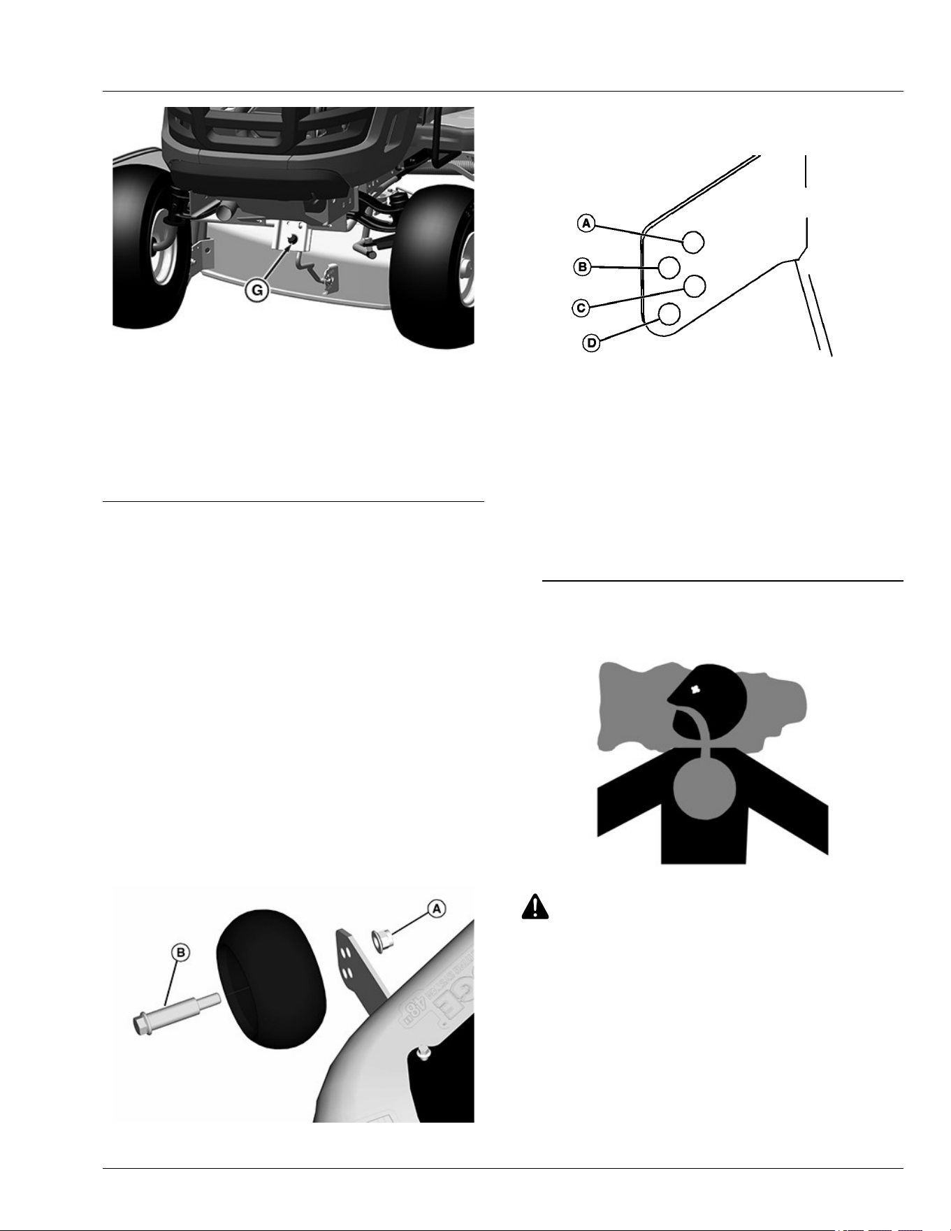
Adjusting Mower Deck Wheels
IMPORTANT: The mower deck can be damaged if
mower wheels are adjusted wrong:
● Bottom of wheels should be approximately 3
to 13 mm (1/8 to 1/2 in) from the ground.
● If mowing at 75 mm (3 in) height of cut or
higher set the anti-scalp wheels in their
lowest position
1. Park machine safely. (See Parking Safely in the
SAFETY section.)
2. Inate tires to the correct pressure.
3. Lower mower deck to the desired mowing position.
NOTE: Bottom of wheels should be approximately 3-13
mm (1/8-1/2 in.) from the ground.
GXAL41988—UN—04MAR13
4. Check each mower wheel position. Remove nut (A)
and bolt (B), and move mower wheel to proper hole.
GXAL41989—UN—04MAR13
A—38 mm (1.5-In.) or less
B—51 mm (2-In.)
C—64 mm (2.5-In.)
D—76 mm (3-In.) and above
5. Install bolts and nuts to lock wheels in position.
Tighten nuts to specications.
Specication
Mower Deck Wheel
Nut—Torque. . . . . . . . . . . . . . . . . . . . . . . . . . . . . 25 lb·ft (34 N·m)
JS86122,0000312-19-11JUL14
Testing Safety Systems
MXAL42804—UN—09APR13
CAUTION: Avoid injury! Engine exhaust fumes
contain carbon monoxide and can cause
serious illness or death.
Do not run an engine in an enclosed area, such
as a garage, even with doors or windows
opened.
Move the machine to an outside area before
running the engine.
The safety systems installed on your machine should be
checked before each machine use. Be sure that you
have read the machine operator’s manual and are
familiar with the operation of the machine before
performing these safety system checks.
Operating
30-4

Use the following checkout procedures to check for
normal operation of machine.
If there is a malfunction during one of these procedures,
do not operate machine. See your dealer or other
service provider for service.
Perform these tests in a clear open area. Keep
bystanders away.
SR99263,0000296-19-29JUL25
Testing Park Brake Switch
1. Park machine safely. (See Parking Safely in the
SAFETY section.)
2. Sit on seat.
3. Unlock the park brake.
4. Try to start engine.
Result: Engine must not turn over. If engine turns over,
there is a problem with your safety interlock circuit.
MP47322,00F4638-19-09APR19
Testing Park Brake
1. Park machine safely. (See Parking Safely in the
Safety section.)
2. Lock the park brake.
3. Pull out on bypass control valve rod to engage.
4. Try to push machine manually.
Result: Park brake must prevent machine from moving.
If machine moves, the park brake requires adjustment.
SR99263,0000318-19-06APR20
Testing Attachment Engagement Switch or
Lever
CAUTION: Avoid injury! The mower blades
should stop in approximately ve seconds
when the mower or PTO is disengaged.
If you believe that your blades may not be
stopping in that period of time, take your
machine to your dealer or other service
provider where they can safely check and
service your machine.
1. Park machine safely. (See Parking Safely in the
Safety section.)
2. Sit on seat.
3. Lock the park brake.
4. Engage mower:
● On models with electric attachment engagement
switch, pull up switch.
● On models with mechanical attachment
engagement lever, push lever forward.
5. Try to start engine.
Result: Engine must not start. If engine starts, there is a
problem with your safety interlock circuit.
SR99263,0000299-19-29JUL25
Testing Seat Switch
1. Park machine safely. (See Parking Safely in the
SAFETY Section.)
2. First test:
a. Lock park brake.
b. Start engine.
c. Move throttle lever up to maximum engine
speed.
d. Engage mower.
e. Raise up o seat. Do not get o machine.
Result: Engine and mower blades should stop. If
engine and mower blades do not stop, there is a
problem with your safety interlock circuit.
3. Second test:
a. Disengage mower.
b. Start engine.
c. Unlock park brake.
d. Raise up o seat. Do not get o machine.
Result: Engine should stop. If engine does not stop,
there is a problem with your safety interlock circuit.
4. Third test:
a. Lock park brake.
b. Disengage mower.
c. Start engine.
d. Raise up o seat. Do not get o machine.
Result: Engine should continue to run. If engine
stops, there is a problem with your safety interlock
circuit.
MP47322,00F463B-19-19MAR13
Testing Reverse Implement Option (RIO)
1. Park machine safely. (See Parking Safely in the
Safety section.)
2. Start engine.
Operating
30-5
3. Engage attachment engagement switch or lever to
start attachment.
CAUTION: Avoid injury! Rotating blades are
dangerous. Children or bystanders may be
injured by runover and rotating blades.
Before backing up, carefully check the area
around the machine.
4. Look behind the vehicle to be sure that there are no
bystanders.
5. Begin reverse travel by depressing reverse pedal.
Result: Attachment and engine should stop operation. If
attachment or engine continues to operate as machine
begins travel in reverse, do not continue to operate
machine. If Engine or attachment continues to operate
in reverse, then contact an authorized service center.
SR99263,000029A-19-16JUL20
Using the Park Brake
CAUTION: Avoid injury! Children or bystanders
may attempt to move or operate an unattended
machine.
Always lock the park brake and remove the key
before leaving the machine unattended.
Locking Park Brake:
1. Push and hold brake pedal down.
2. Pull park brake lever up to lock park brake.
3. Release brake pedal. Pedal should stay down and
park brake lever should stay locked.
Unlocking Park Brake:
1. Push and hold brake pedal down.
2. Push park brake lever down to unlock park brake.
3. Release brake pedal.
SR99263,000029B-19-03APR20
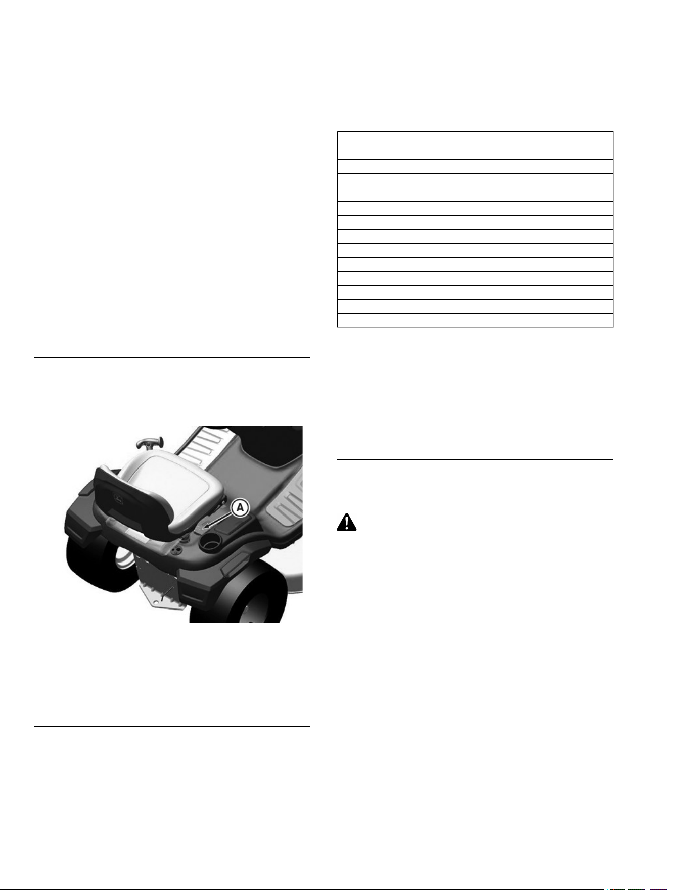
Checking Fuel Level (If Equipped)
APY36157—UN—10JUL20
Check fuel level in fuel tank (A).
MG39705,00004AA-19-30JUN20
Using Hourmeter and MowerPlus™ Fuel
Gauge (If Equipped)
Using Hourmeter
APY36158—UN—10JUL20
1. The hour meter (A) shows the number of hours the
engine has run.
2. Follow the service timetable on the maintenance
schedule located under the hood and centered
toward the rear of the machine. For specic service
procedures, see the Service section of this manual.
3. The hour meter cannot be reset.
4. The hour meter display will always be on.
5. The decimal point ashes while the hour meter is
accumulating time.
Operating
30-6
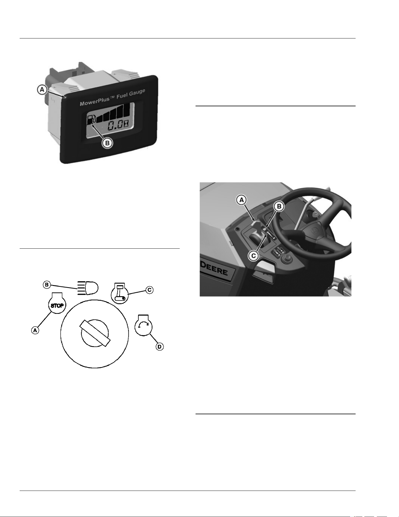
Using MowerPlus™ Fuel Gauge (If Equipped)
APY33785—UN—24JUL20
1. The hour meter (A) shows the number of hours the
engine has run. The hour meter is always visible and
active, it cannot be reset.
2. Fuel level (B) indicated by the graph by ve
segments in increasing height. When fuel tank has
emptied to approximately 20%, the last segment
ashes indicating approximately 30 minutes of fuel
remaining.
MG39705,00004AB-19-27JUL20
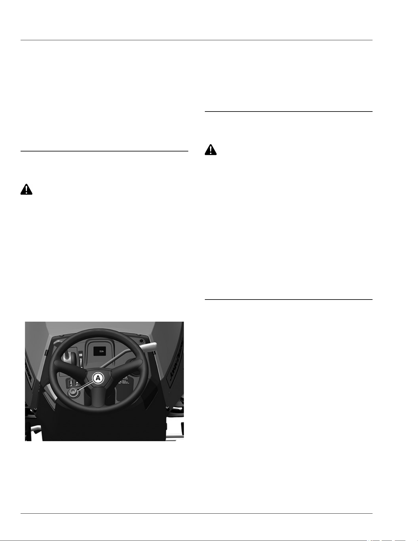
Using Key Switch and Headlights
GXAL41992—UN—04MAR13
A—STOP Position
B—HEADLIGHTS ON Position
C—RUN Position
D—START Position
Engine O
NOTE: Headlights will drain the battery rapidly if key
switch is left in headlights on position (B) with the
engine o.
● To turn on headlights, turn the key switch to
HEADLIGHTS ON position (B).
● To turn o headlights, turn the key switch to STOP
position (A).
Engine On
● To turn on headlights, start engine, then turn key
switch from RUN position (C) to HEADLIGHTS ON
position (B).
● To turn o headlights, turn the key switch from
HEADLIGHTS ON position (B) to RUN position (C).
MX00654,000039A-19-25APR19
Starting the Engine
1. Operator must sit on the seat.
2. Disengage attachment engagement lever / switch.
(See Engaging and Disengaging Mower in the
Operating section.)
3. Fully depress the brake pedal.
APY38190—UN—07JUL20
4. Push throttle lever (A) forward to full throttle position
(C).
5. Turn ignition to START (not more than 5 seconds).
6. If engine is cold:
● Push throttle lever (A) into choke area (B) and
hold.
● Turn ignition to START (not more than 5 seconds).
● Release choke to full throttle position.
NOTE: Run engine at full throttle when operating
mower or other attachments.
SR99263,000029E-19-05OCT20
Idling the Engine
Unnecessary engine idling may cause engine or
transmission damage. Excessive idling can
cause engine overheating, carbon build-up, and
poor performance.
Operating
30-7
Idling or low throttle operation while mowing,
climbing hills, or towing could result in
transmission overheating. Always operate at
full throttle once the engine is warm.
Do not operate machine with hood open. Hood
must be closed for proper engine cooling and
exhaust.
● Engine is air cooled and needs a large volume of air
to keep cool. Keep air intake screen on top of engine
clean.
● Keep hood closed when engine is idling.
SR99263,0000039-19-10JUL18
Stopping the Engine
IMPORTANT: Avoid damage! Do not stop the engine
by moving choke control to the choke position.
Backre, re or engine damage can occur.
Follow recommended procedure for stopping
engine.
1. Let engine run at high throttle without load for a few
seconds.
2. Turn key to STOP position. Engine will stop and
headlights will turn o.
3. Remove key.
4. Lock the park brake.
SR99263,000029D-19-03APR20
Using Travel Controls on Hydrostatic
Transmission
CAUTION: Avoid injury! Children or bystanders
may be injured by runover and rotating blades.
Before traveling forward or rearward:
● Carefully check the area around the machine.
● Disengage the mower before backing up.
Travel Forward
APY33767—UN—06APR20
Tractor with PTO Lever
● Push down the forward travel pedal (A).
Travel in Reverse
NOTE: Any operating attachment and the engine stop
as the reverse motion pedal is pressed with
attachment engaged.
APY36160—UN—10JUL20
Tractor with PTO Switch
1. Disengage attachment:
● On models with mechanical attachment
engagement lever (B), pull lever back to the o
position.
● On models with electric attachment engagement
switch, push switch in location (C) (not shown
above) down to the o position.
2. Look behind the machine to be sure there are no
bystanders nearby.
3. Slowly push down the reverse travel pedal (D).
Operating
30-8
Stopping
1.Remove foot from travel pedal.
2.Depress brake pedal.
Emergency Stopping
1.Remove foot from travel pedal.
2.Depress brake pedal.
3.Turn key switch to stop (O) position. Do not release
brake pedal until all moving parts have stopped.
4.If possible, lock the park brake.
SR99263,00002FF-19-01JUL20
Using The Reverse Implement Option (RIO)
CAUTION: Avoid injury! Children or bystanders
may be injured by runover and rotating blades.
Before traveling forward or rearward:
● Carefully check the area around the machine.
● Disengage the mower before backing up.
NOTE: Backing up while the mower is engaged is
strongly discouraged. The Reverse Implement
Option should be used only when operating another
attachment or when the operator deems it
necessary to reposition the machine with the
mower engaged.
1. Stop forward travel.
2. Look behind the machine to be sure there are no
bystanders.
APY36159—UN—10JUL20
3. Push and hold in the reverse implement switch (A)
while depressing reverse pedal slightly.
NOTE: If the engine and mower stop while repositioning
the machine, return the attachment engagement
lever/switch to the o position. Start engine and
engage mower. Begin again with Step 2.
4. Release the reverse implement switch (A) and
reposition the machine as the machine begins to
move rearward.
5. Resume forward travel. The mower should continue
operating.
6. Repeat procedure to position the machine again.
SR99263,00002EB-19-01JUL20
Using Cruise Control (If Equipped)
CAUTION: Avoid injury! Do not use cruise
control when going down hills. Machine speed
will increase. Operate machine in a large, open
area to learn how the cruise control works.
Use cruise control when you want to maintain travel
speed without having to hold the forward travel pedal
down. Cruise control operates only for forward travel.
Engage Cruise Control
1. Push forward pedal down until you reach desired
travel speed.
2. Pull cruise control lever up and release forward pedal
to lock the cruise control.
Disengage Cruise Control
● Depress brake pedal, tap on forward pedal or push
cruise control lever down to the o position.
SR99263,00002EC-19-28JUL25
Engaging and Disengaging Mower
NOTE: Put attachment lift lever in transport position to
transport machine or when parking machine.
1. Start engine and run at half speed for a couple of
minutes to warm up.
2. Lower mower deck to desired cutting height position.
NOTE: Throttle lever should be at full throttle position
before engaging mower to avoid stalling engine.
3. Push throttle lever up to the full throttle position.
4. Engage mower.
● On models with electric attachment engagement
switch: Pull up switch.
● On models with mechanical attachment
engagement lever: Push lever forward.
NOTE: The mower and engine stops as the reverse foot
pedal is depressed.
Operating
30-9
5. Disengage mower blades before moving in reverse
or stopping engine.
● Machines with mechanical attachment
engagement lever: Pull lever back.
● Machines with electric attachment engagement
switch: Push down switch.
SR99263,0000338-19-12MAY20
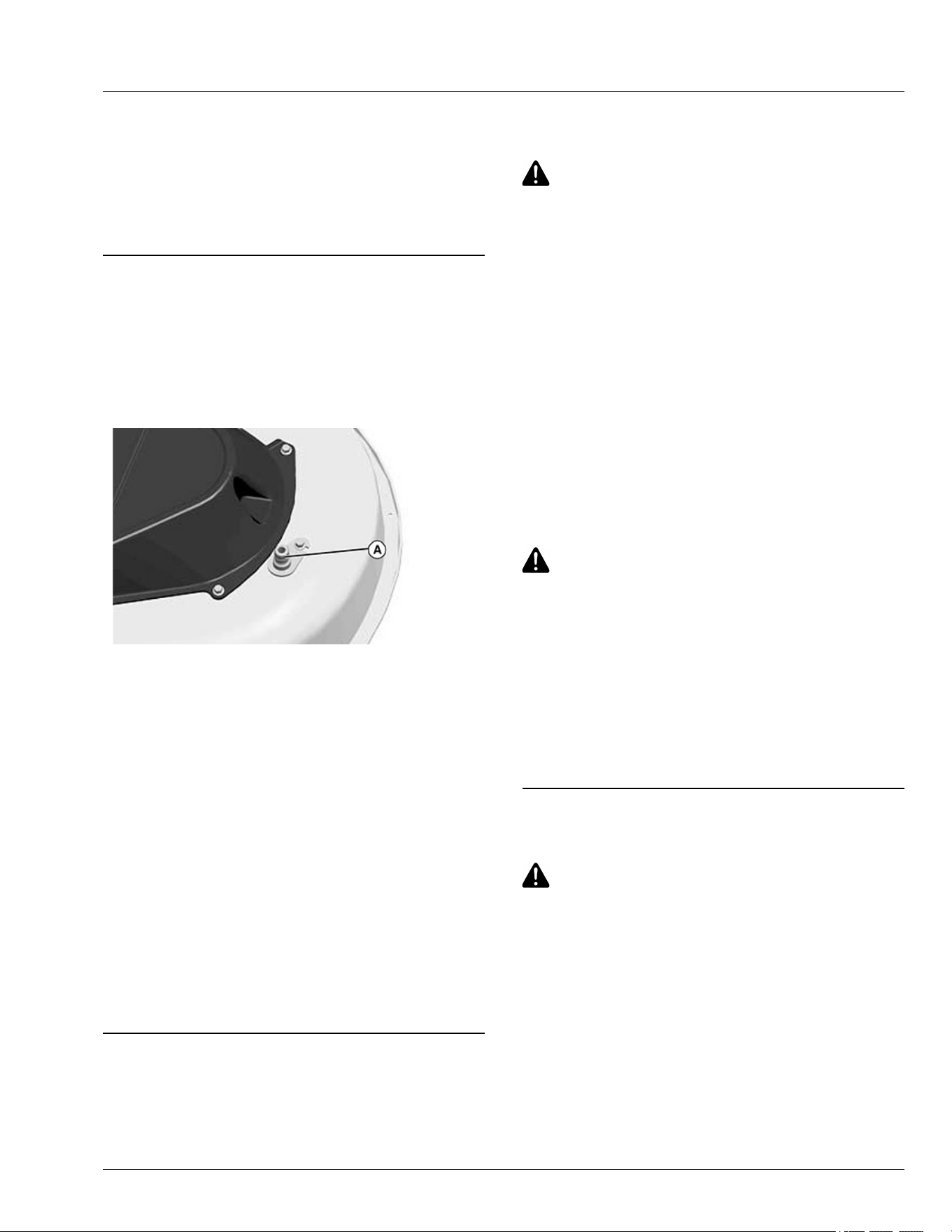
Using Wash Port to Clean Mower Deck
NOTE: Follow this procedure after each use to prevent
buildup and remove corrosive lawn chemicals.
1. Park machine safely. (See Parking Safely in the
Safety section).
GXAL41997—UN—04MAR13
2. Attach quick-coupler to garden hose.
3. Attach garden hose with quick-coupler to wash port
(A) on the mower deck.
4. Turn on water.
5. Start engine.
6. Run at full throttle.
7. Engage mower blades.
8. Flush water under deck for approximately one
minute.
9. Disengage mower blades.
10. Stop engine.
11. Turn o water and remove garden hose and quick-
coupler from wash port.
12. Remove quick-coupler from garden hose and store
for future use.
OUO1023,00001B0-19-01MAR13
Unplugging Mower, Bagger, or Material
Collection System
CAUTION: Avoid injury! Do not attempt to
unplug attachment with the machine running.
● Rotating blades are dangerous. Shut o the
engine and remove the key before getting o
the seat to inspect the machine and
attachment.
● Thrown objects can cause serious injury.
Make sure that all machine parts are stopped
before raising hopper top or removing
chutes.
Checking for Plugging While Driving
If grass builds up in the front of the mower discharge
chute, check for plugged chute or problems with blower
assembly (if equipped).
If there is a trail of clippings behind mower or clippings
blow to the side, check for plugged chute, full collector
bags, or problems with blower assembly.
Removing Debris from Inspection Points:
CAUTION: Avoid injury! Do not use hands or
feet to clear plugged mower deck or blower
assembly. Stored energy can cause blades to
rotate.
1. Park machine safely. Wait for all moving parts to stop
before getting o to inspect machine.
2. Open hopper cover. Check chute outlet.
3. Remove chute from the mower deck or blower
assembly. Check chute inlet.
4. Check under the mower deck for debris.
MP47322,00F4646-19-10JUL20
Moving Machine by Hand
CAUTION: Avoid injury! When the bypass valve
is open, the machine has unrestricted motion.
● Do not open the bypass valve when the
machine is stopped on an incline to prevent
it from going downhill out of control.
IMPORTANT: Avoid damage! Transmission damage
may occur if the machine is towed or moved
incorrectly:
● Move machine by hand only.
● Do not use another vehicle to move machine.
● Do not tow machine.
1. Unlock the park brake.
Operating
30-10
APY36161—UN—10JUL20
2. On hydrostatic models: Pull out on bypass valve
control rod (A).
3. Push machine to desired location.
IMPORTANT: Avoid damage! Hydrostatic
transmission might be damaged if the bypass
valve control rod is not pushed back to
operating position before attempting to start
the engine. Do not start or operate the machine
with the bypass valve control rod in the pulled-
out position.
4. Push bypass valve control rod back in.
5. Lock the park brake.
MG39705,00004EE-19-28JUL20
Transporting Machine on Trailer
NOTE: Trailer capacity must exceed combined machine
weight and attachment weight. (See Specications
section in Operator’s manual.)
Be sure the trailer has all necessary lights and signs
required by law.
CAUTION: Avoid injury! Use extra care when
loading or unloading the machine onto a trailer
or truck.
● Park trailer on a level surface.
● Use of a trailer with sides is recommended.
● Keep wheels away from drop-os and edges.
● Back slowly and in a straight line.
● Close fuel shut-o valve, if your machine is
equipped.
● Do not secure machine using optional
bumper as this can dislodge during
transport.
IMPORTANT: Avoid damage! Transporting a
machine on a trailer or on a truck bed at high
speeds can result in hood or engine cover
raising and possibly coming o machine if not
secured.
● Position machine on trailer so hood or
engine cover opens from rear of trailer to
prevent wind from blowing hood or cover
open.
● Secure hood or engine cover with existing
machine locks or latches.
● Secure hood or engine cover with tie down
straps if no locks or latches exist.
1. Park trailer on a level surface.
2. Raise mower deck, if installed, before driving
machine onto trailer.
3. Drive machine onto heavy-duty trailer. Position
machine on trailer so hood or engine cover will not
raise in wind while being transported.
4. Lower mower deck completely.
5. Lock park brake.
6. Turn o machine and remove key.
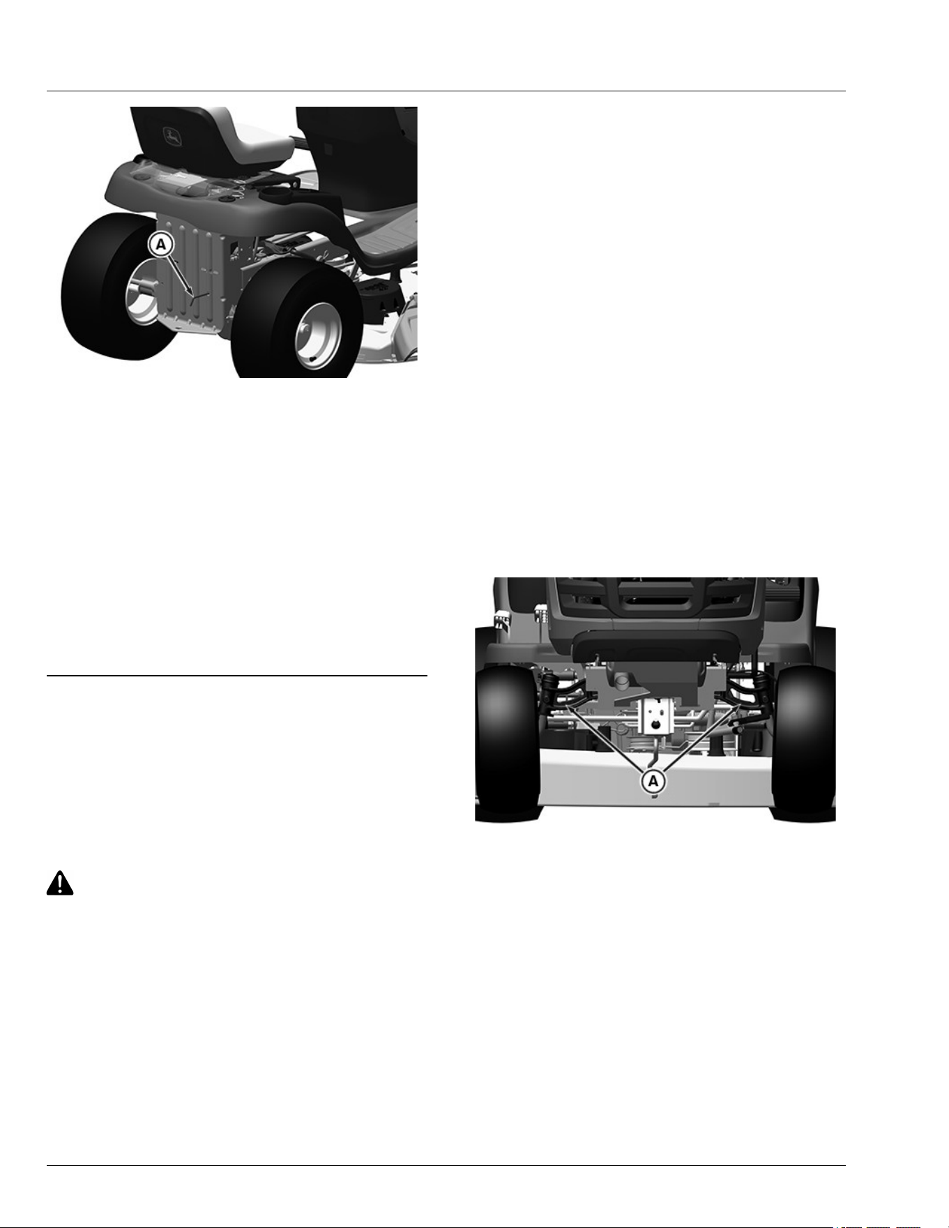
APY36162—UN—10JUL20
7. Secure front of machine at both sides of the axle at
points (A) to trailer with heavy-duty straps, chains, or
cables. Straps must be directed down and outward
from machine.
IMPORTANT: Avoid damage! Do not secure machine
using transmission housing.
Operating
30-11
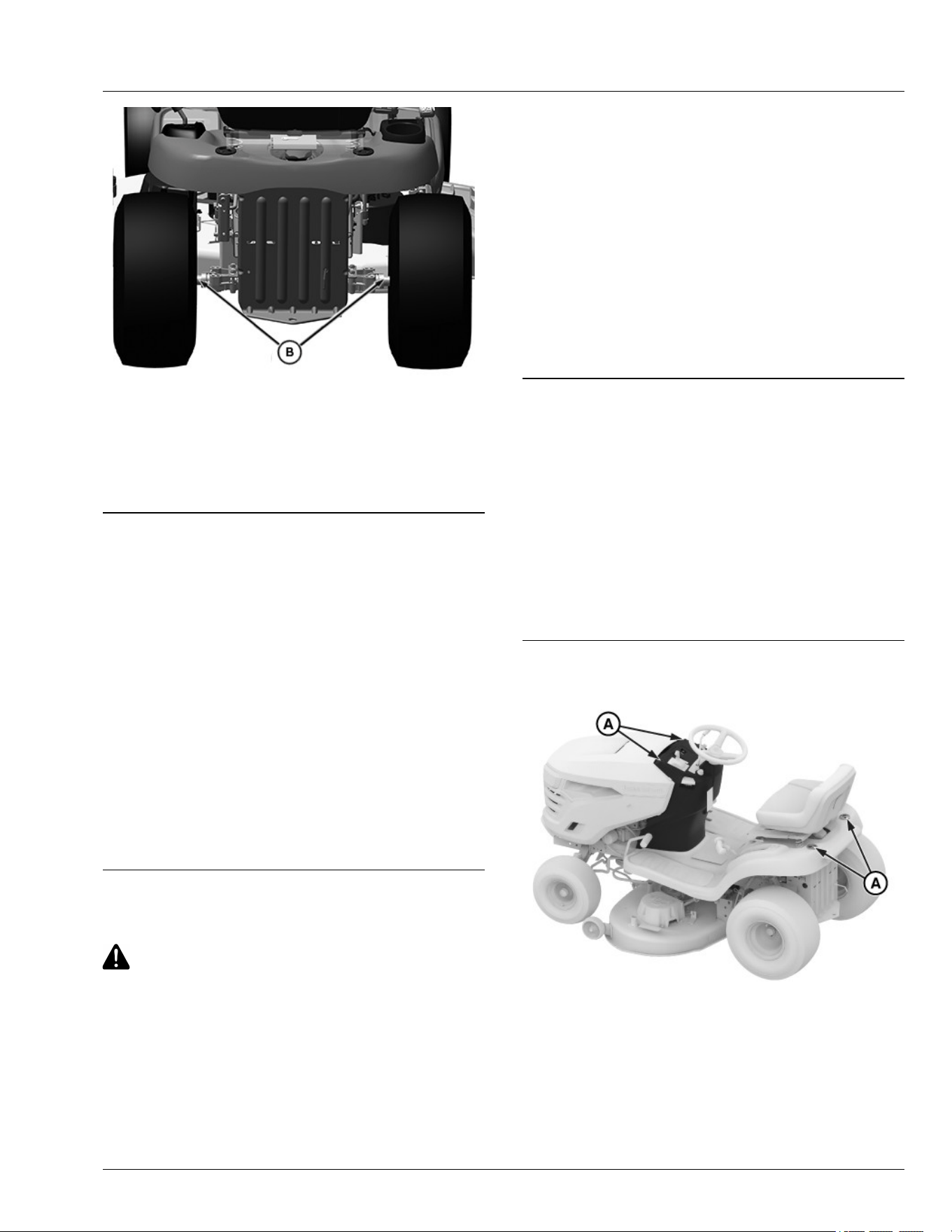
PY43279—UN—29MAY17
8. Secure rear of machine at both sides of the axle at
points (B) to trailer with heavy-duty straps, chains, or
cables. Straps must be directed down and outward
from machine.
9. Secure hood to prevent from lifting while driving.
SR99263,00002ED-19-02JUL20
Transporting Material Collection System (If
Equipped)
If the material collection system is left on the machine
during transport, follow these guidelines when trailering
the unit:
● Empty the cloth bags and remove them from the
hopper. Full bags add extra weight which can
overstress the hopper frame on rough roads. At road
travel speeds, wind can cause premature wear of the
cloth bags.
● Make sure that the hopper cover is latched securely
to the hopper frame.
● If the unit is transported over long distances or at
high speeds, remove the rear bagger or power ow
chute before transport.
TH84124,000020A-19-10APR19
Using Weights
CAUTION: Avoid injury! The machine may
become unstable when operating on slopes
and/or with some attachments.
Use weights to improve stability when
operating on slopes or using attachments.
Remove weights when not required.
IMPORTANT: Avoid damage! Never use liquid in
tires or wheel weights as ballast. Transmission
damage can occur.
When rear ballast is needed, use only the
approved rear weight bracket and attaching
weights.
NOTE: See your John Deere dealer or other service
provider for recommended weights.
● Install front weights for added stability and steering
control when you use equipment, such as the rear-
mounted grass bagger.
● Install rear weights when using the snow blade or
snowblower.
● Remove weights when not required.
MX00654,000039C-19-17OCT25
Using Tire Chains
IMPORTANT: Avoid damage! Do not use chains with
mower deck.
Tire chains are recommended for use with most front
attachments. Remove tire chains before installing
mower deck.
See your attachment operator’s manual for tire chain
recommendation. See your John Deere dealer or other
purchase provider.
SR99263,0000150-19-17OCT25
Using Accessories
GX624364—UN—29MAY24
Using CargO Mount System
The front and rear CargO Mount system brackets (A)
can be used for easy attachment of selected optional
equipment.
Use John Deere approved optional equipment only. See
Operating
30-12
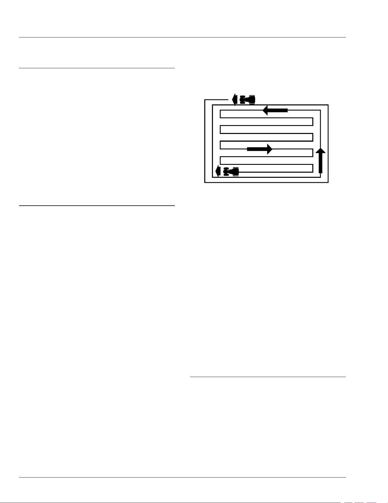
your authorized service center for approved optional
equipment.
gvg6119,1715763751909-19-22MAY24
Choosing Mower Blades
Three types of mower blades are available to use with
100 series models.
● 3-N-1 blades. These are general purpose blades that
are best suited for side-discharge operation, but can
be used with a bagger attachment, or with a mulch
cover installed. They are not designed for optimal
performance when bagging or mulching.
● Bagger blades. These blades are designed for
optimal performance when used with bagger
attachments.
● Mulching blades. These blades are designed for
optimal performance when used with a mulch cover
installed.
MG39705,00004AC-19-02JUL20
Mowing Tips
The following recommendations produce the best lawn
cut quality and appearance:
● Keep mower blades sharp. Dull blades tear grass;
tips of grass then turn brown.
● Mowing at fast speed increases the amount of grass
that collects in the hopper or bagger (where
applicable).
● Cutting grass too short may kill grass and let weeds
grow easily.
Specication
Suggested Finished Cut Height
Range—Height. . . . . . . . . . . . . . . . . . . 44—70 mm (1.75—2.75 in)
● Adjust cutting height to remove only 1/3 of the grass
at a time.
● Do not mow wet grass. If this cannot be avoided,
increasing deck rake from 6.4 mm (1/4 in) to 12.7 mm
(1/2 in) will improve the machines ability to cut in wet
conditions without plugging the discharge chute.
● Mow grass often. Short grass clippings will decay
quickly.
● Mow with engine at full throttle.
● Adjust travel speed to match mowing conditions:
- Travel at slow speed when you mow thick, tall
grass, make sharp turns or trim around objects.
- Travel at moderate speed when you mow thin
grass.
● Use a dierent mowing pattern each time you mow.
Overlap mowing paths to specied distance.
Specication
Mowing Path
Overlap—Distance. . . . . . . . . . . . . . . . . . . . 50—100 mm (2—4 in)
● Drive over ridges and through shallow ditches
straight-on, not at an angle.
GXAL42115—UN—04MAR13
● Mow around the outside twice, then mow inside in
straight passes. Best cut is achieved when mowing in
a straight line.
● When mowing or mulching near pavement, overlap
the pavement by 50 mm (2 in) to allow clippings to
dispense over grass.
● A thick layer of mulched leaves can prevent sunlight
from getting to grass and smother it. Taller grass
heights allow mulched leaves to dispense easier in
lawn. Mulch leaves several times if needed.
● Use a thatcher in late spring or summer to pull up
dead grass and aerate ground.
● For Mulching Mower:
- Shorter cut heights provide better cut quality, but
may leave noticeable clippings. Higher cut
heights reduce clippings, but cut quality may
decline.
- Increasing the cutting height by a minimum of 6.4
mm (1/4 in) can improve mulching performance.
- If engine begins to labor during mulching
operations, increase deck height to reduce the
amount of grass being added into the mower
deck.
gvg6119,1719203569788-19-23JUN24
Towing Loads
IMPORTANT: Avoid damage! Towing excessive
trailer loads at full speeds for long distances
and up slopes can stress drivetrain
components. To avoid damage to drivetrain
components, use the following guidelines.
● Total towed weight must not exceed 226.79 kg (500
lb). Use counterweights or wheel weights as
Operating
30-13

described in an attachment or pulling machine
operator’s manual.
● When towing over 150 kg (350 lb), depress forward
travel pedal no more than halfway to avoid
transmission damage. Always run tractor at full
throttle when towing loads.
● Avoid inclines greater than a 10° slope while towing
to avoid damage to the pulling machine. Use the
Slope Guide located in this operator’s manual to
ensure proper machine towing operation. See
SAFETY section, Operating on Slopes in this
operator’s manual for additional information.
IMPORTANT: Avoid damage! Always run tractor at
full throttle when PTO is engaged and when
towing loads.
RM87422,0000261-19-04AUG25
Operating
30-14

Servicing Your Machine
IMPORTANT: Avoid damage!
Operating in extreme conditions may require
more frequent service intervals:
● Engine components may become dirty or
plugged when operating in extreme heat,
dust or other severe conditions.
● Engine oil can degrade if machine is
operated constantly at slow or low engine
speeds or for frequent short periods of time.
High-pressure washing can cause damage to
machine components. It is recommended that
your vehicle be washed by hand or with a
garden hose using mild soap.
Avoid spraying water with any great force near
or into the following places:
● Air intake
● Electrical connections (including battery
compartment)
● Wheel bearings
● Radiator (if equipped)
● Warning labels
● Other labels
● Ignition switch
● Instrument panel (gauges and switches)
● Breather/tube vents
● Mower spindles
● Mower idler bearings
● Transmission cooling fans
Please use the following timetables to perform routine
maintenance on your machine.
Park the vehicle safely. (See Park Safely in the SAFETY
Section.)
OUMX068,00006EF-19-22NOV16
Service Intervals
Initial Service 8 Hours
● Lubricate mower spindles.
● Check the mower deck spindle brakes (manual
PTO).
● Lubricate front axle pivot and axle spindles.
Every 25 Hours
● Lubricate mower spindles.
● Lubricate front axle pivot and axle spindles.
Yearly or Every 50 Hours (Whichever Comes First)
● Replace engine oil and lter, or Easy Change ™ 30-
Second Oil Change System (if equipped).
● Replace air lter element(s).
● Replace fuel lter.
● Replace spark plug(s).
● Clean engine cooling ns.
● Clean or replace emission lter (if equipped).
● Sharpen or replace mower blades.
● Check or replace mower drive belts.
● Check and level mower deck.
● Clean mower deck.
● Check mower deck spindle brakes (manual PTO).
● Clean battery terminals.
Every 200 Hours
● Check and adjust valve clearance. (See your John
Deere dealer or other service provider for this
service.)
SDHTXN6,1746463748018-19-04JUN25
Service Intervals
35-1
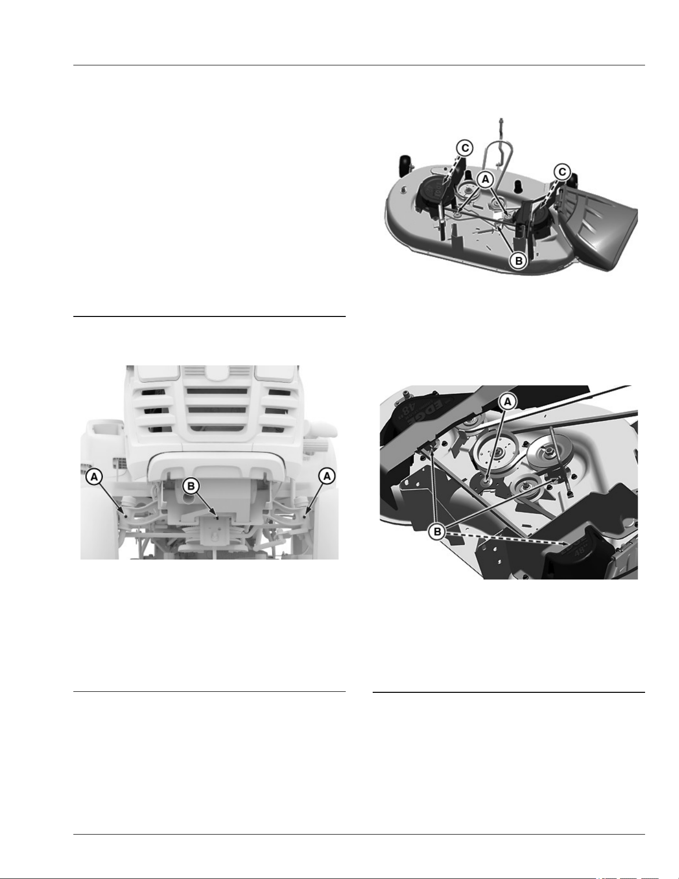
Grease
IMPORTANT: Avoid damage! Use recommended
John Deere greases to avoid component failure
and premature wear.
The following grease is recommended for service:
● John Deere Multi-Purpose HD Lithium Complex
Grease
● Grease-Gard Premium Plus
Not all grease types are compatible; John Deere does
not recommend mixing greases. If using any product
other than the recommended grease in service, purge
any remaining grease from the system before
application. If not practical, grease twice as often until all
old grease is purged from the system.
OUMX068,0000642-19-12APR24
Lubricating Front Axle
GX624365—UN—23MAY24
Wheel Spindles and Bushings
● Lubricate front wheel spindle grease tting (A) , with
one or two shots of general all-purpose grease.
Front Axle Pivot
● Lubricate front axle center pivot grease tting (B) with
one or two shots of general all-purpose grease.
gvg6119,1716185004505-19-22MAY24
Lubricating Pivot Points
107 cm (42 in) Mower Deck:
APY38196—UN—28JUL20
A— Blade Brake Pivot (2)
B— Deck Idler Pivot
C— Spindle Grease Fitting (2)
● Lubricate the two spindle grease ttings (C) with one
or two shots of general all-purpose grease.
122 cm (48 in) Mower Deck:
APY38197—UN—07JUL20
A— Deck Idler Pivot
B— Spindle Grease Fitting (3)
● Lubricate the deck idler pivot (A) with a general all-
purpose spray lubricant.
● Lubricate the three spindle grease ttings (B) with
one or two shots of general all-purpose grease.
BVVMSIT,00003A5-19-28JUL20
Service Lubrication
40-1
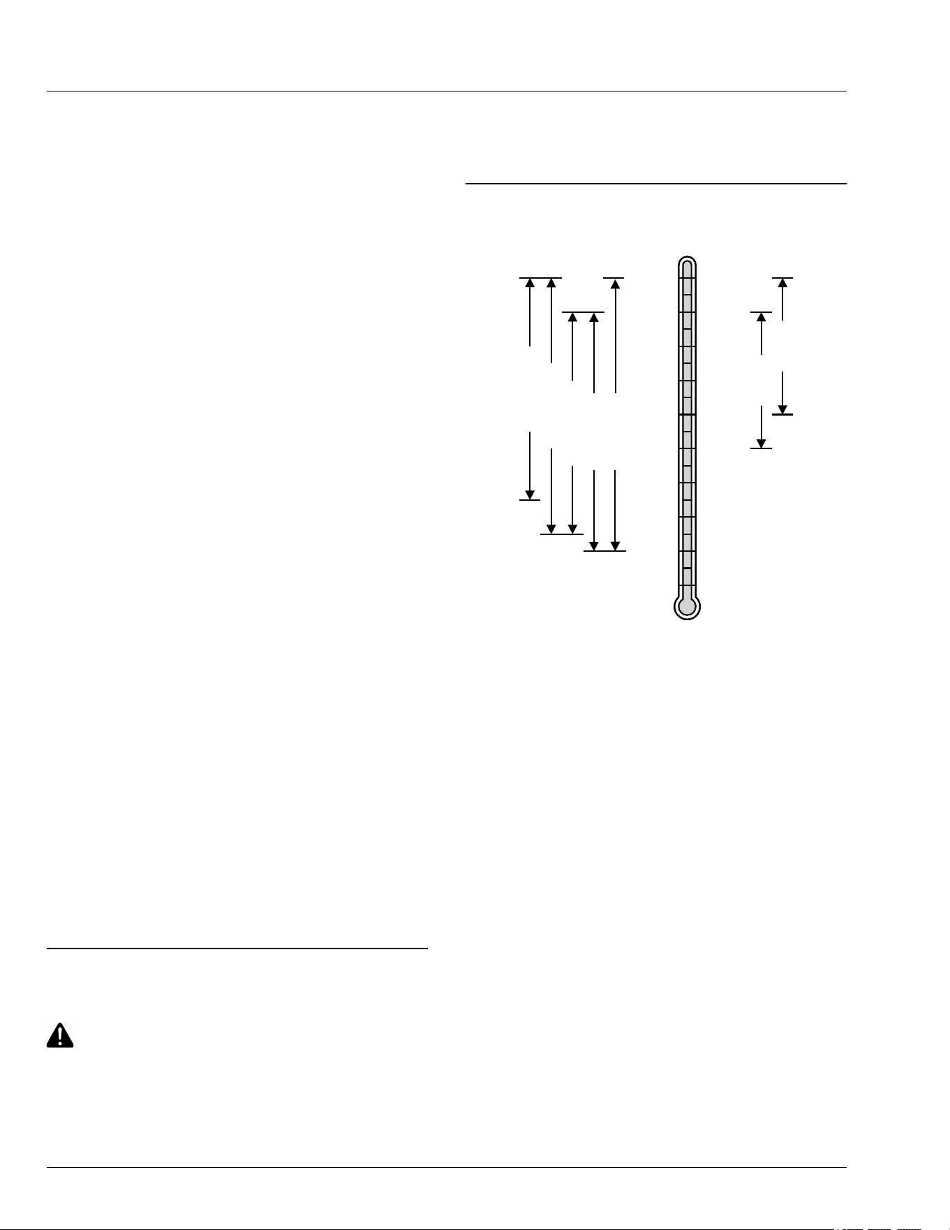
Emissions Service Information
Within the warranty period, John Deere will reimburse
reasonable service costs incurred at service providers
outside the John Deere authorized network only in an
unsafe, emergency condition if an authorized John
Deere dealer is not available and the failure does not
arise from the owner’s misuse or failure to perform
required maintenance. An emergency situation exists
under this section if, after 30 days, the authorized John
Deere network is unable to perform the repairs or
source replacement parts.
Emission Control System Certication Label
NOTE: Tampering with emission controls and
components by unauthorized personnel may result
in severe nes or penalties. Emission controls and
components can only be adjusted by EPA and/or
CARB authorized service centers. Contact your
John Deere Retailer concerning emission controls
and component questions.
The presence of an emissions label signies that the
engine has been certied with the United States
Environmental Protection Agency (EPA) and/or
California Air Resources Board (CARB).
The emissions warranty applies only to those engines
marketed by John Deere that have been certied by the
EPA and/or CARB; and used in the United States and
Canada in o-road mobile equipment.
Altitude Adjustment (Gasoline or Propane
Converted Engines Only)
If your engine features a carburetor it is calibrated by the
engine manufacturer and is not adjustable.
If your engine is operated at altitudes below 610 m
(2,000 ft.), a high altitude carburetor jet kit is not
required. If your engine is operated at altitudes above
610 m (2,000 ft.), a high altitude carburetor jet kit may
be required for proper engine performance and
emissions control. Operating the engine with the wrong
carburetor conguration at a given altitude may increase
the engine’s emissions and decrease fuel eciency and
performance.
See a qualied service provider for details on jet kit
requirements for your specic product.
TC00531,00000EC-19-20FEB25
Avoid Fumes
CAUTION: Avoid injury! Engine exhaust fumes
contain carbon monoxide and can cause
serious illness or death.
Do not run an engine in an enclosed area, such
as a garage, even with doors or windows
opened.
Move the machine to an outside area before
running the engine.
MP47322,00F4652-19-13JAN15
Gasoline Engine Oil
SAE 5W-40
SAE 30
SAE 40
SAE 5W-30
SAE 10W-30
SAE 10W-40
SAE 15W-40
0
o
C
-10
o
C
-20
o
C
-30
o
C
-40
o
C
10
o
C
20
o
C
30
o
C
40
o
C
50
o
C
32
o
F
14
o
F
-4
o
F
-22
o
F
-40
o
F
50
o
F
68
o
F
86
o
F
104
o
F
122
o
F
TS1744—UN—25AUG20
Oil Viscosities for Air Temperature Ranges
Use oil viscosity based on the expected air temperature
range during the period between oil changes.
Using single viscosity grade oils such as SAE 30 or SAE
40 can reduce oil consumption in air cooled engines.
The following oils are approved:
● John Deere Plus-50™ II
● John Deere Turf-Gard™
Other oils may be used if they meet one or more of the
following:
● ILSAC GF-6A
● API Service Category SP
● API Service Category SN
● API Service Category SM
● API Service Category SL
● API Service Category SJ
● ACEA Oil Sequence A3/B3
● ACEA Oil Sequence A3/B4
● ACEA Oil Sequence A5/B5
● ACEA Oil Sequence C5
Plus-50 is a trademark of Deere & Company
Turf-Gard is a trademark of Deere & Company
Service Engine
45-1
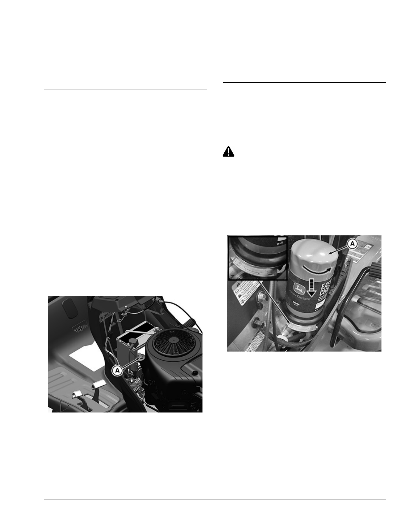
● ACEA Oil Sequence C4
● ACEA Oil Sequence C3
● ACEA Oil Sequence C2
● ACEA Oil Sequence C1
DX,ENOIL2-19-15JUL20
Checking Engine Oil Level
IMPORTANT: Avoid damage! Failure to check the oil
level regularly could lead to serious engine
problems if oil level is out of the operating
range:
● Check oil level before operating.
● Check oil level when the engine is cold and
not running.
● Keep oil level between the dipstick marks.
● Shut o engine before adding oil.
NOTE: Check oil twice a day if you run engine over 4
hours in a day.
Make sure engine is cold when checking engine oil
level.
1. Park machine safely on level surface. (See Parking
Safely in the Safety section.)
2. Lift hood.
3. Clean area around dipstick to prevent debris from
falling into crankcase.
APY36165—UN—10JUL20
Twin Cylinder Engine Shown
4. Remove dipstick (A). Wipe with clean cloth.
5. Install and tighten dipstick.
6. Remove dipstick.
7. Check oil level on dipstick. Oil must be between ADD
and FULL marks.
8. If oil level is low, add oil to bring oil level no higher
than FULL mark on dipstick. Do not overll.
9. Install and tighten dipstick. Lower hood.
MG39705,00004AD-19-15JUL20
Changing John Deere Easy Change™ 30-
Second Oil Change System (If Equipped)
● For engines equipped with the Easy Change system.
● Replaces the lter and a portion of the engine oil.
CAUTION: Avoid Injury! Park the machine
safely using park brake, turn o engine, and
disconnect spark plug wires.
IMPORTANT: Avoid Damage! Oil should be changed
when engine is cool. It is not necessary to run
engine prior to changing oil.
1. Lift hood.
2. Remove shipping tie strap (if equipped) on rst
service only.
APY08908—UN—29MAY18
A— Easy Change Oil System (ECOS)
3. Remove old easy change oil system (ECOS) (A) by
rotating the lter 90 degrees counterclockwise.
Push down while rotating.
4. Wipe clean any drips.
Service Engine
45-2
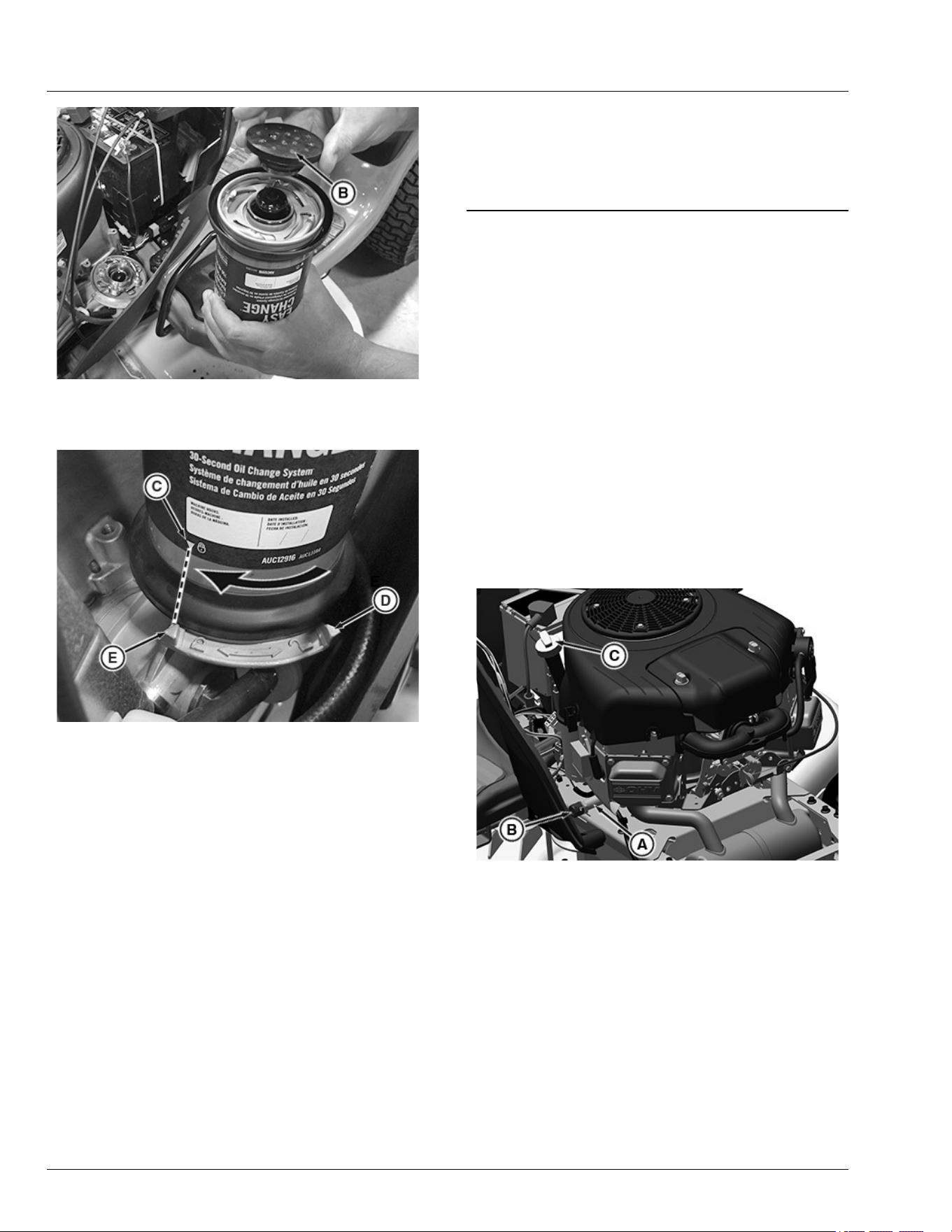
PY44545—UN—03AUG17
B— Rubber Cap
5. Remove rubber cap (B) from new ECOS.
APY08907—UN—29MAY18
Shown in Locked Position
C— Alignment Pointer on the ECOS
D— Unlocked Pointer
E— Locked Pointer
6. Install new ECOS by aligning the alignment pointer
(C) on the ECOS with the unlocked pointer (D) on
the engine. Rotate the ECOS 90 degrees clockwise,
until the detent lock engages and the lock pointer on
the ECOS (C) and engine (E) are aligned.
IMPORTANT: Avoid Damage! Keep turning the
ECOS until the detent is engaged and the lock
symbols are aligned.
7. Check oil level with the dipstick. Add oil if
necessary.
8. Connect spark plug wires, start, and run engine at
idle to check for leaks. Stop engine. Fix any leaks
before operating.
9. Lower the hood.
10. The rubber cap can be installed on the used ECOS.
NOTE: Many local government recycling programs,
authorized retailers, auto repair stations, and auto
parts stores puncture and recycle used oil lters
and oil.
SR99263,000014A-19-09JUL20
Changing Engine Oil and Filter on models
not equipped with the John Deere Easy
Change™ 30-Second Oil Change System
IMPORTANT: Avoid damage! Change the oil more
often if the vehicle is used in extreme
conditions:
● Extremely dusty conditions.
● Frequent slow or low-speed operation.
● Frequent short trips.
1. Run engine to warm oil.
2. Park machine safely. (See Parking Safely in the
SAFETY section.)
3. Lift hood.
4. Remove closeout panels.
APY36166—UN—10JUL20
Twin Cylinder Engine is Shown.
5. Put drain pan under drain valve (A).
6. Rotate and remove drain cap (B) and drain oil into
oil drain pan. Allow oil to drain completely.
7. Remove dipstick (C).
Service Engine
45-3
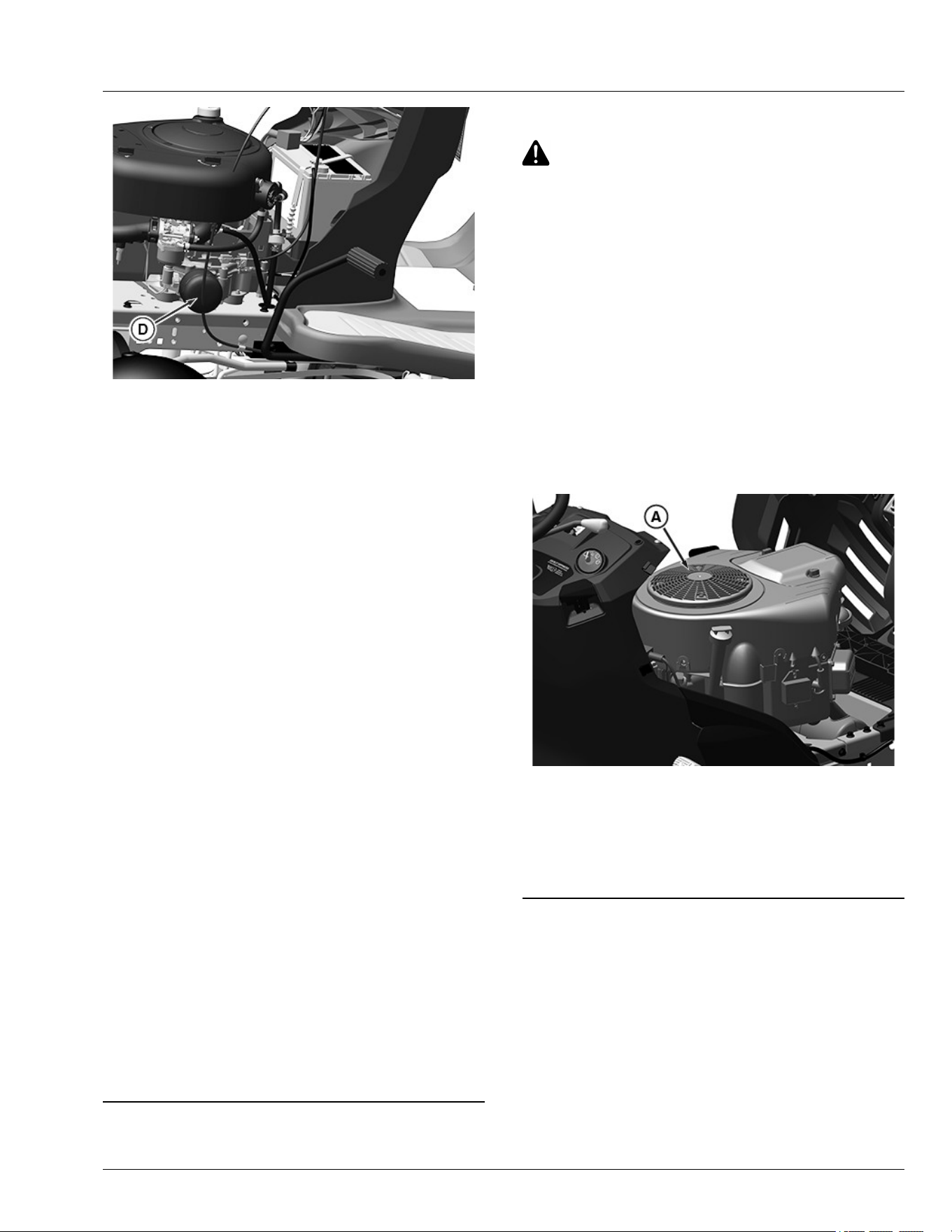
APY36168—UN—10JUL20
Single Cylinder Engine Shown
8. Replace oil lter (D).
a. Wipe dirt from around oil lter.
b. Place a drain pan or funnel under lter tray.
c. Remove old lter and lter gasket and dispose
of properly. Wipe up any spilled oil.
d. Put a light coat of fresh, clean oil on the new
lter gasket.
e. Install replacement oil lter by turning oil lter
to the right (clockwise) until the rubber gasket
contacts lter base. Tighten lter an additional
one-half turn.
9. Install drain cap.
IMPORTANT: Avoid damage! Do not overll.
Overlling can cause smoking, hard starting,
fouling of spark plug, and oil saturation of air
lter.
10. Add oil no higher than FULL mark on dipstick. Use
approximately the amount of oil listed in the
Specications section. Do not overll.
11. Install dipstick.
12. Connect spark plug wires to start and run engine at
idle to check for leaks. Stop engine. Fix any leaks
before operating.
13. Check oil level. Add oil if necessary.
14. Install closeout panels and lower hood.
NOTE: Many local government recycling programs,
authorized retailers, auto repair stations, and auto
parts stores will puncture and recycle used oil lters
and oil.
MG39705,00004AE-19-24JUL20
Cleaning Air Intake Screen and Engine Fins
CAUTION: Avoid Injury! Compressed air can
cause debris to y a long distance.
● Clear work area of bystanders.
● Wear eye protection when using compressed
air for cleaning purposes.
● Reduce compressed air pressure to 210 kPa
(30 psi).
IMPORTANT: Avoid Damage! An obstructed air
intake screen can cause engine damage due to
overheating. Keep air intake screen and other
external surfaces of the engine, including
cooling ns, clean at all times to allow adequate
air intake.
1. Park machine safely. (See Parking Safely in the
Safety section.)
2. Lift hood.
APY36167—UN—10JUL20
Twin cylinder engine shown
3. Clean air intake screen (A), cooling ns and external
surfaces with rag, brush, vacuum or compressed air.
4. Lower hood.
OUO1023,00001C3-19-15JUL20
Checking and Cleaning Air Cleaner
Elements
Checking and Cleaning Air Cleaner Elements (S100,
S110, S120, S130, and S140)
1. Park the machine safely. (See "Parking Safely" in the
SAFETY section.)
2. Let the engine cool.
3. Lift the hood.
4. Clean dirt and debris from the air cleaner cover.
Service Engine
45-4
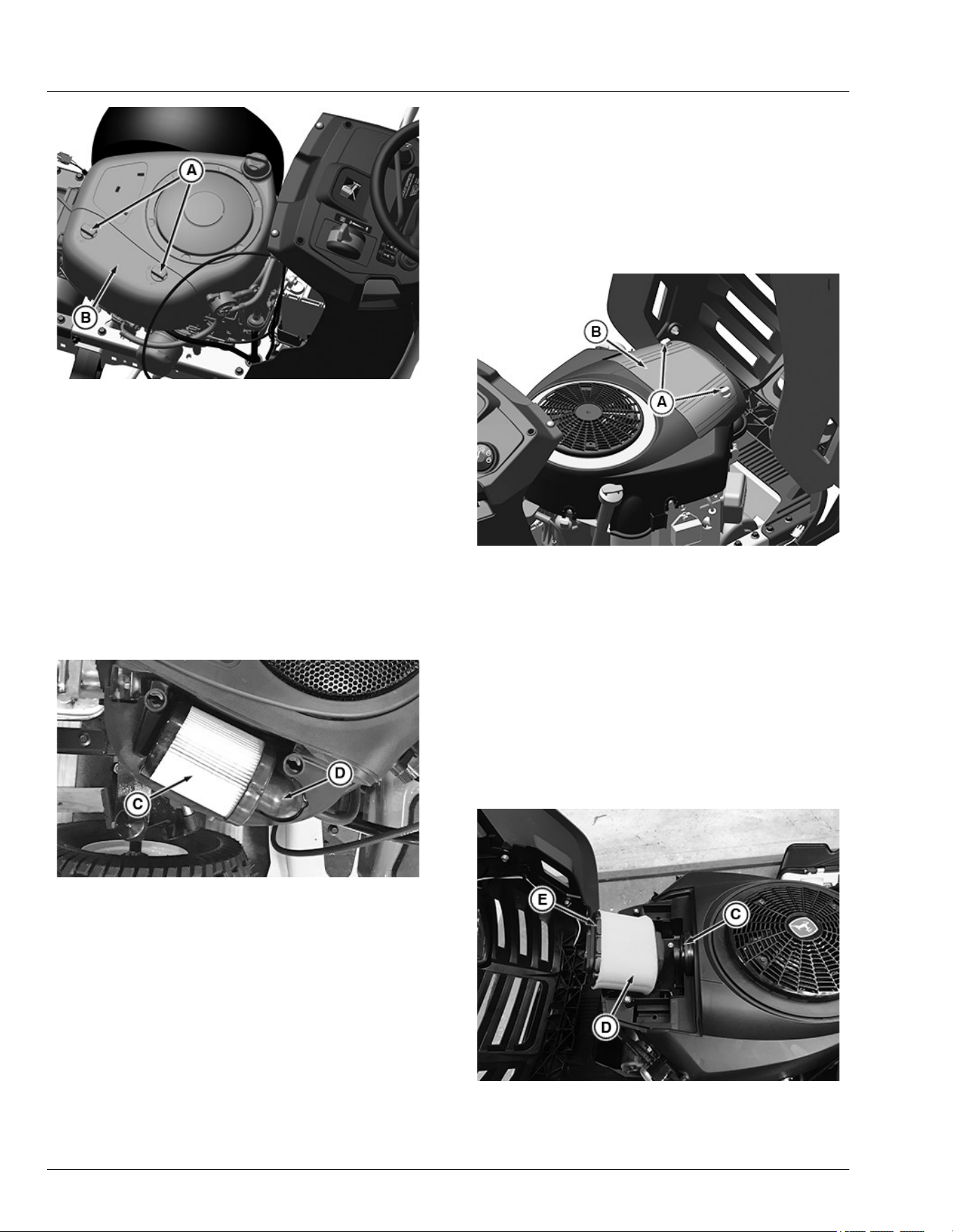
APY36169—UN—10JUL20
5. Lift the latch (A) to unlock the cover (B). Lift the cover
forward and remove it.
IMPORTANT: Avoid Damage! Dirt and debris can
enter the engine through a damaged lter
element:
● Do not wash the paper element.
● Do not attempt to clean paper element by
tapping it against another object.
● Do not use pressurized air to clean the
element.
● Replace the element only if it is very dirty,
damaged or if the seal is cracked.
PY44553—UN—14AUG17
6. Inspect the paper lter element (C) without removing
it. If the paper lter element is damaged or dirty,
replace it with a new lter:
● Clean air cleaner base very carefully, preventing
any dirt from falling into carburetor.
● Carefully pull the paper element from the air
cleaner elbow (D).
● Install new paper lter element back onto air
cleaner elbow.
7. Install the air cleaner cover and push the latch down
to lock.
8. Lower the hood.
Checking and Cleaning Air Cleaner Elements (S160,
S170, and S180)
1. Park the machine safely. (See "Parking Safely" in
the SAFETY section.)
2. Let the engine cool.
3. Lift the hood.
4. Clean dirt and debris from the air cleaner cover.
APY36171—UN—10JUL20
5. Loosen the two knobs (A) and remove the cover (B).
IMPORTANT: Avoid Damage! Dirt and debris can
enter the engine through a damaged lter
element:
● Do not wash the paper element.
● Do not attempt to clean the paper element by
tapping it against another object.
● Do not use pressurized air to clean the
element.
● Replace the element only if it is very dirty,
damaged or if the seal is cracked.
APY36198—UN—10JUL20
6. Pull lter assembly from air cleaner base (C).
Inspect the foam precleaner (D) without removing it.
If the foam precleaner is dirty:
Service Engine
45-5
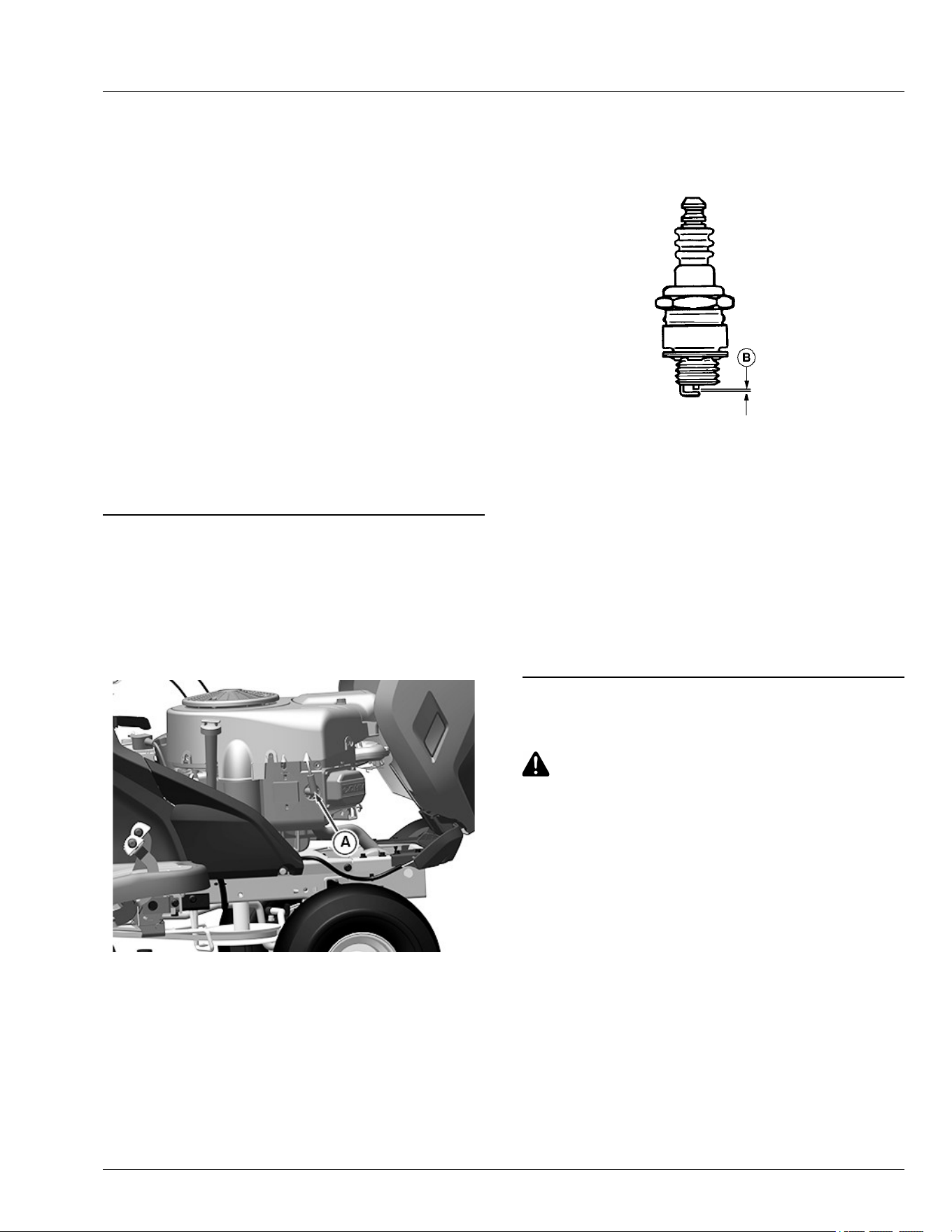
a. Remove it from the paper lter carefully.
b. Wash the precleaner in a solution of warm
water and liquid detergent. Do not use oil.
c. Rinse the precleaner thoroughly. Squeeze out
excess water with a dry cloth until the
precleaner is completely dry.
7. Inspect the paper lter element (E). If the paper lter
element is damaged or dirty, replace it with a new
lter.
8. Clean the air cleaner base very carefully, preventing
any dirt from falling into the carburetor.
9. Install the foam precleaner on the paper lter
element.
10. Install the new lter assembly back onto the air
cleaner base.
11. Install the air cleaner cover and tighten the two
knobs.
12. Lower the hood.
SDHTXN6,1745841602070-19-05MAY25
Checking Spark Plug
1. Park machine safely. (See Parking Safely in the
SAFETY section.)
2. Let engine cool.
3. Lift hood.
APY36172—UN—10JUL20
Twin cylinder engine shown
4. Disconnect spark plug wire(s) (A), one on each side
on V-twin engines.
5. Remove spark plug(s).
6. Clean spark plug carefully with a wire brush.
7. Inspect spark plug for:
● Cracked porcelain.
● Pitted or damaged electrodes.
● Other wear or damage.
8. Replace spark plug as necessary.
GXAL42022—UN—04MAR13
9. Check plug gap (B) with a wire feeler gauge. To
change gap, move the outer electrode.
Gap must meet specications.
Specication
Spark Plug—Gap. . . . . . . . . . . . . . . . . . . . . . . 0.030 in. (0.76 mm)
10. Install and tighten spark plugs to specications.
Specication
Spark Plug—Torque. . . . . . . . . . . . . . . . . . .. . . . . 15 lb-ft (20 N·m)
11. Connect spark plug wire(s) and lower hood.
MG39705,00004AF-19-02JUL20
Replacing Fuel Filter
CAUTION: Avoid injury! Fuel vapors are
explosive and ammable:
● Do not smoke while handling fuel.
● Keep fuel away from ames or sparks.
● Shut o engine before servicing.
● Cool engine before servicing.
● Work in a well-ventilated area.
● Clean up spilled fuel immediately.
NOTE: Change lter when fuel is low.
1. Park machine safely. (See Parking Safely in the
Safety section).
2. Lift hood.
3. Let engine cool.
4. Put a drain pan under the fuel lter.
Service Engine
45-6

MXT015030—UN—02JUL15
5. Slide hose clamps (A) away from the fuel lter (B)
using pliers.
6. Disconnect hoses from the lter.
IMPORTANT: Avoid damage! Incorrect installation
of the fuel lter may cause engine damage.
Install the lter with the arrow pointing in the
direction of fuel ow (towards the engine) for
proper operation.
7. Connect hoses to the new lter making sure that the
lter arrow is pointing in the direction of the fuel ow.
8. Install clamps and check for leaks.
9. Lower hood.
MG39705,00004C2-19-02SEP20
Spark Arrestor Maintenance (If Equipped)
Spark arrestor assemblies include a screen element
that should be inspected and cleaned
periodically. Visually inspect the screen for tears, broken
wires, or loose welds. Replace the spark arrestor
assembly if any of these conditions exist. If the screen is
determined to be in good condition, proceed with
cleaning the screen by brushing away loose dirt or
carbon using a brush.
RM87422,00002DA-19-05JUL17
Service Engine
45-7

Checking Transmission
The transmission is a sealed component. No
maintenance is required on this transmission. If you
suspect any transmission problems, please contact your
dealer or other service provider.
MP47322,00F465D-19-29JUL25
Service Transmission
50-1
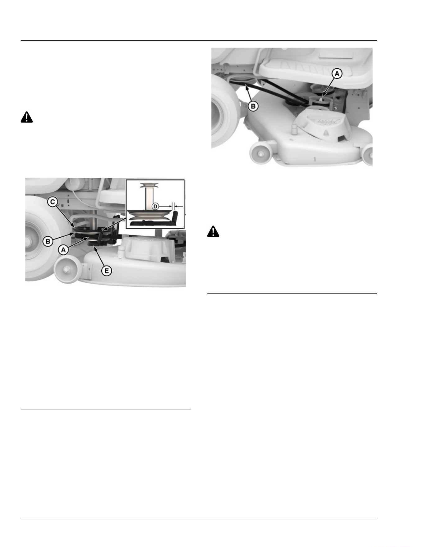
Removing or Installing Mower Drive Belt at
Engine Drive Sheave in Manual PTO
Machines
1. Park machine safely. (See Parking Safely in Safety
section.)
2. Put lift lever in lowest position.
CAUTION: Avoid injury! Component is spring-
assisted and under tension. Injury can occur if
spring-assisted component is released
suddenly.
NOTE: The sheave extension is only applicable for
manual PTO models.
GX633065—UN—25JUN24
A—Belt
B—Drive Sheave
C—Plastic Sheave Extension
D—Gap
E—Belt Keeper
3. Remove belt (A) from the drive sheave (B) through
gap at (D) on both sides by exing the plastic sheave
extension (C). Do not pull down on belt keeper (E).
4. To install the belt (A) on the drive sheave (B), ex the
plastic drive sheave extension (C) through the gap
(D) on both sides between C and E without pulling
down on (E).
gvg6119,1716185642208-19-28JUN24
Removing or Installing Mower Drive Belt at
Engine Drive Sheave in Electronic PTO
Machines
1. Park machine safely. (See Parking Safely in Safety
section.)
2. Put wood blocks under each side of mower deck.
3. Put attachment lift lever in lowest position, bringing
mower deck down onto blocks.
GX619005—UN—26JUN24
4. Put a 15 mm closed-end wrench or a socket on the
idler sheave nut (A) and rotate clockwise to move
idler sheave toward the front of the tractor and hold to
release belt tension.
5. Remove mower drive belt from drive sheave (B).
CAUTION: Avoid injury! Mower lift arms can
pinch ngers. Lift arms are spring loaded and
can snap back when deck is removed.
Lock lift lever before pulling pin to remove
mower deck.
6. Installation is the reverse of removal.
gvg6119,1719231253741-19-27JUN24
Removing Mower Deck
1. Park machine safely. (See Parking Safely in Safety
section.)
2. Put wooden blocks under each side of the mower
deck.
3. Put attachment lift lever in lowest position, bringing
mower deck down onto blocks.
4. Remove the drive belt. (See Removing or Installing
Mower Drive Belt at Engine Drive Sheave in Manual
PTO Machines or Removing or Installing Mower
Drive Belt at Engine Drive Sheave in Electronic PTO
Machines in the Service Mower section.)
Service Mower
55-1
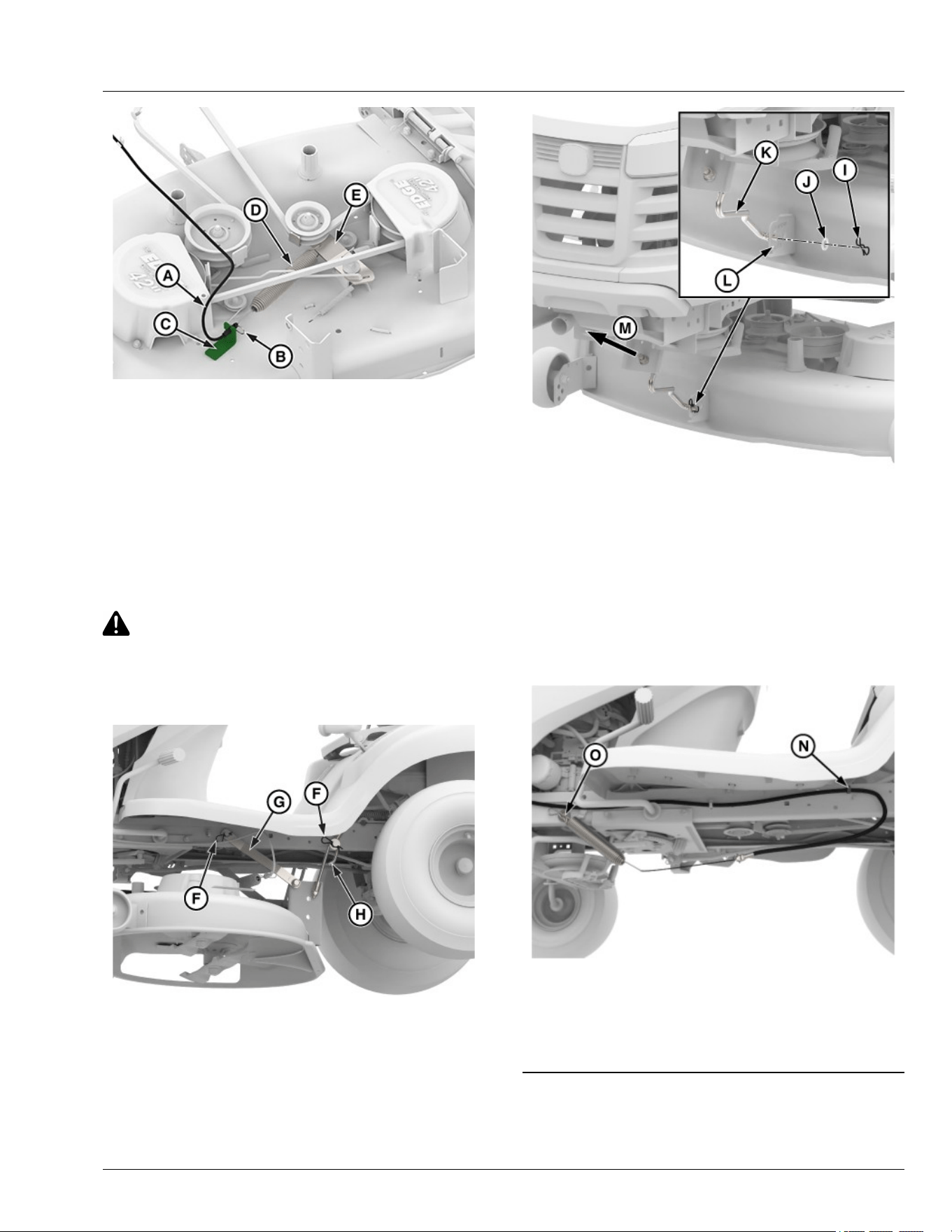
GX624367—UN—30MAY24
NOTE: The removal of the engagment drive cable is
only for Manual PTO machines
On machines with manual PTO mower deck,
disconnect mower engagement drive cable (A) on
the left side of the mower deck.
a. Remove spring locking pin (B), lift up and
remove from bracket (C).
b. Push down on center of spring (D) and pull the
hook out of bracket (E).
CAUTION: Avoid injury! Mower lift arms can
pinch ngers. Lift arms are spring loaded and
can snap back when deck is removed.
Lock lift lever before pulling pin to remove
mower deck.
GX624362—UN—05JUN24
6. Remove spring locking pins (F), washers, pull rear
draft arm (G) and adjustable lift links (H) o of the
pins on each side of machine.
GX633061—UN—01JUL24
7. Remove spring locking pin (I), washer (J), and front
draft rod (K) from the mower deck bracket (L).
8. Remove wooden blocks from both sides and slide
mower deck out from under the machine.
9. To operate the machine without the mower deck see
below step:
● To remove from the machine: Pull front draft rod
(K) out from front of the unit in direction (M)
without removing nut.
GX624344—UN—26JUN24
● On manual PTO mower deck only: Push mower
engagement drive cable into clip (N) and hook end of
the cable spring with hardware (O) into peg on the
left side of machine frame.
gvg6119,1716185663853-19-01JUL24
Service Mower
55-2
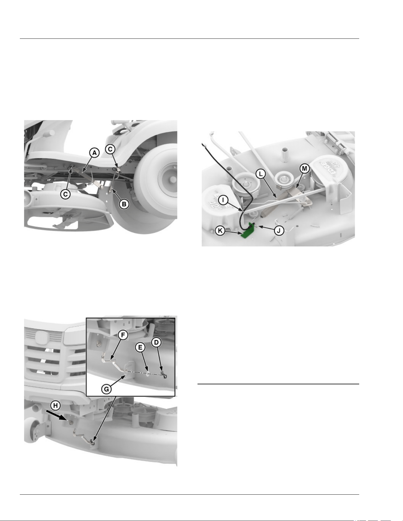
Installing Mower Deck
1. Park machine safely. (See Parking Safely in Safety
section.)
2. Put attachment lift lever in the transport position.
3. Slide mower under machine.
4. Put wooden blocks under each side of mower deck.
5. Put attachment lift lever in lowest position.
GX624369—UN—23MAY24
6. Fasten rear draft arm (A) and adjustable lift link (B)
on each side with washers and spring locking pins
(C).
IMPORTANT: Avoid damage! To prevent clutch
damage, make sure that front draft rod is
installed correctly. Secure rod with washer and
spring locking pin on the left side of mower
deck bracket.
GX633062—UN—01JUL24
7. Install front draft rod (F) into the front rod hanger
bracket in direction (H) and then into the mower
deck bracket (G) in the upper hole, without
removing the nut on the front draft rod.
8. Secure front draft rod with washer (E) and spring
locking pin (D).
9. Install the drive belt. (See Removing or Installing
Mower Drive Belt at Engine Drive Sheave in Manual
PTO Machines or Removing or Installing Mower
Drive Belt at Engine Drive Sheave in Electronic
PTO Machines in the Service Mower section.)
GX619013—UN—01JUL24
10. On manual PTO mower deck only: Connect mower
engagement drive cable (I) on the left side of the
mower deck.
a. Ensure that the spring cable is routed under
the belt.
b. Install spring locking pin (J), lift down, and
install into bracket (K).
c. Push on center of spring (L) and install into the
idler sheave bracket M).
11. Lift mower deck to transport positon and then
remove wood blocks from both sides of mower
deck.
12. Level mower deck. (See Checking and Adjusting
Mower Deck Level in the Operating section.)
gvg6119,1716185698820-19-01JUL24
Replacing Mower Drive Belt—42 in Deck
1. Park machine safely. (See Parking Safely in the
Safety section.)
2. Remove mower deck. (See Removing Mower Deck
in the Service Mower section.)
Service Mower
55-3
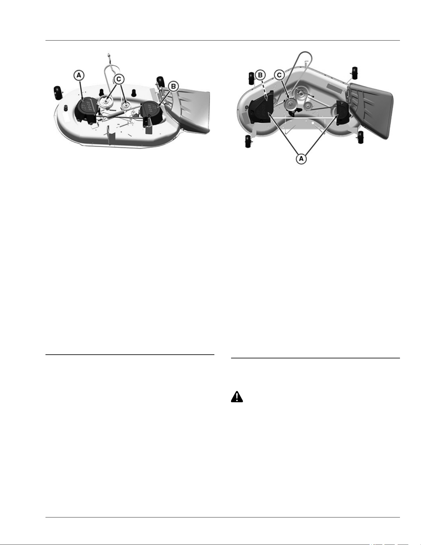
APY22313—UN—18JUL19
3. Remove drive belt:
a. Remove three capscrews and belt shield (A).
b. Remove two capscrews and belt shield (B).
c. Loosen sheaves (C).
d. Remove mower belt.
4. Inspect belt for wear or damage; replace as
necessary.
5. Clean top surface of mower deck and sheaves.
6. Install belt on mower deck as shown. Make sure belt
is in the groove of each sheave.
7. Tighten sheaves to specications.
Specication
Mower Deck Drive Sheave Nuts
(42 in Mower Deck)—Torque. . . . . . . . . . . . . . . . . 47 N·m (35 lb-ft)
8. Install belt shields.
9. Install mower deck.
gvg6119,1717493094281-19-01JUL24
Replacing Mower Drive Belt—48 in and 54
in Decks
1. Park machine safely. (See Parking Safely in Safety
section.)
2. Remove mower deck. (See Removing Mower Deck
in the Service Mower section.)
APY22314—UN—24JUL19
Remove ve capscrews and left and right belt shields
(A).
3. Remove drive belt.
a. Loosen left side sheaves (B) and (C).
b. Remove mower belt.
4. Inspect belt for wear or damage; replace as
necessary.
5. Clean top surface of mower deck and sheaves.
6. Install belt on mower deck as shown. Make sure belt
is in the groove of each sheave.
7. Tighten sheaves to specications.
Specication
Mower Deck Drive Sheave Nuts
(48 in and 54 in Mower
Deck)—Torque. . . . . . . . . . . . . . . . . . . . . . . . . . . 47 N·m (35 lb-ft)
8. Install belt shields.
9. Install mower deck.
gvg6119,1717493128049-19-01JUL24
Checking for Bent Mower Blades
CAUTION: Avoid Injury! Blades are sharp.
Always wear gloves when handling blades or
working near blades.
Replace blades if defective. Never straighten or
weld them.
1. Park machine safely. (See Parking Safely in the
Safety section.)
2. Raise mower deck to highest position to access
blades.
Service Mower
55-4
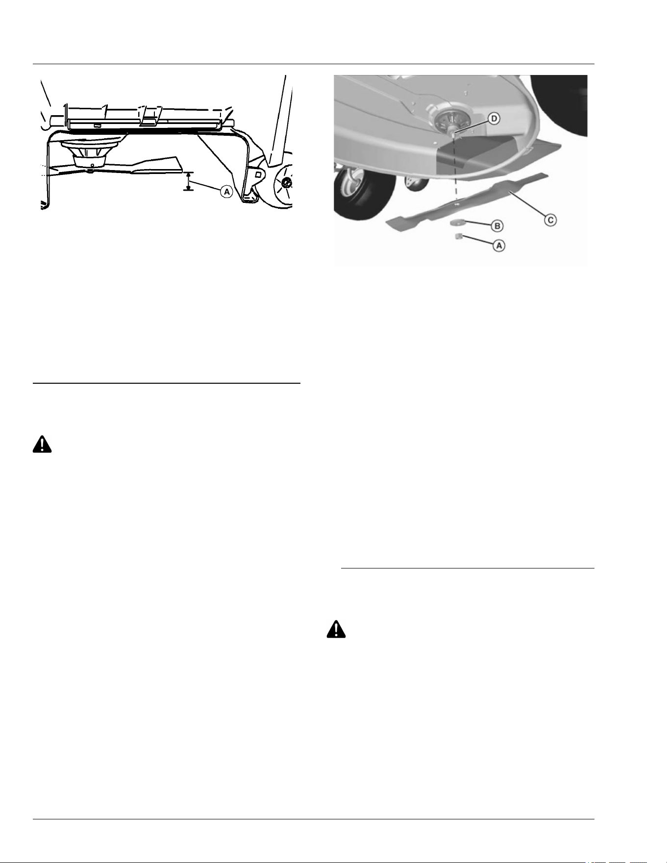
MXAL42867—UN—09APR13
Mower Deck With Side Discharge Used for Illustration
3. Measure distance (A) between blade tip and at
ground surface.
4. Rotate blade 180° and measure distance between
other blade tip and at ground surface.
5. Install new blade if the dierence between the two
measurements is more than 3 mm (1/8 in).
6. Repeat for all blades.
SR99263,00002AA-19-10APR20
Servicing Mower Blades
CAUTION: Avoid injury! Rotating blades are
dangerous. Before adjusting or servicing
mower:
Disconnect spark plug wires or battery negative
(-) cable to prevent engine from starting
accidentally.
Always wear gloves when handling mower
blades or working near blades.
Removing Mower Blades
1. Park machine safely. (See Parking Safely in Safety
section.)
2. Raise mower deck to gain access to mower blades. If
necessary, remove mower deck.
3. Block mower blade with a piece of wood to prevent it
from spinning.
GXAL42597—UN—19MAR13
4. Loosen and remove nut (A), washer (B), and blade
(C).
5. Inspect blades; sharpen, balance, or replace blades
as necessary.
Installing Mower Blades
1. Position mower blade (C) with the cutting edge
towards the ground.
2. Align the splined center hole in the blade with the
splined spindle shaft (D) and put the blade onto the
mower spindle shaft.
3. Install washer, with cupped side towards blade, and
install nut to secure blade onto splined spindle shaft.
4. Block mower blade with a piece of wood to prevent
spinning and tighten nut.
5. Using 15/16 in socket, tighten 5/8 in blade nut to
specications.
Specication
Mower Deck Blade Nut—Torque . . . . . . . . . . . . . . . 88 N·m (65 lb·ft)
SR99263,00002E3-19-06APR20
Sharpen Blades
CAUTION: Avoid injury! Blades are sharp.
Always wear gloves when handling blades or
working near blades.
Always wear safety eye protection when
grinding.
● Sharpen blades with grinder, hand le, or electric
blade sharpener.
Service Mower
55-5
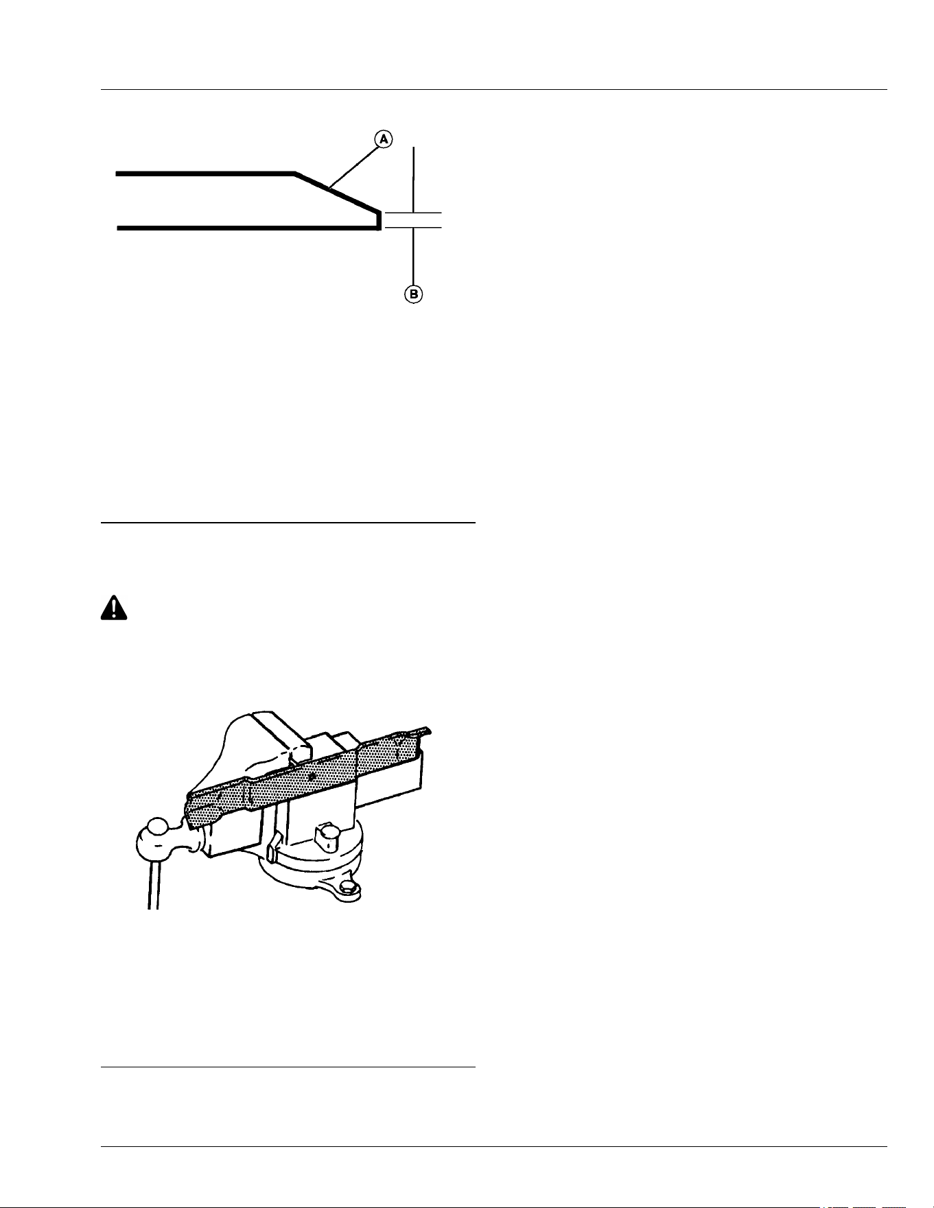
GXAL42041—UN—04MAR13
● Keep original bevel (A) when grinding.
● The blade cutting edge (B) should meet
specications.
Specication
Mower Blade Cutting
Edge—Distance. . . . . . . . . . . . . . . . . . . . . . . . . . . . . . . . 0.40 mm
(1/64 in)
● Balance blades before installing.
MX00654,000039E-19-17AUG23
Balance Blades
CAUTION: Avoid injury! Blades are sharp.
Always wear gloves when handling blades or
working near blades.
1. Clean blade.
GXAL42042—UN—04MAR13
2. Put blade on nail in a vise. Turn blade to horizontal
position.
3. Check balance. If blade is not balanced, heavy end
of blade will drop.
4. Grind bevel of heavy end. Do not change blade
bevel.
MX00654,000039F-19-17AUG23
Service Mower
55-6
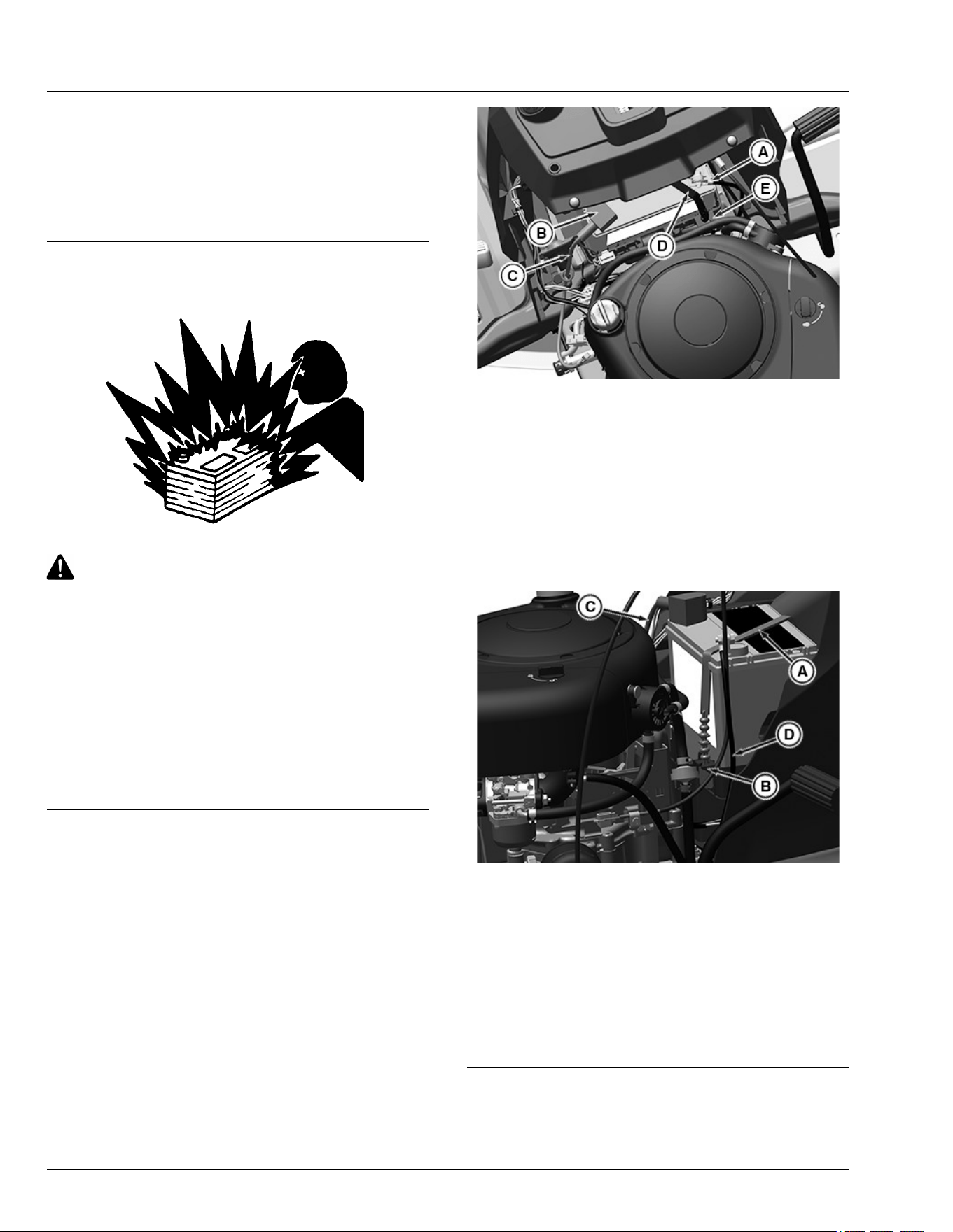
Electrical
WARNING: Avoid injury! Battery posts, terminals and
related accessories contain lead and lead components,
chemicals known to the State of California to cause
cancer and reproductive harm. Wash hands after
handling.
MP47322,00F466E-19-04AUG25
Service the Battery Safely
MXAL42869—UN—09APR13
CAUTION: Avoid injury! The battery produces a
ammable and explosive gas.
To prevent the battery from exploding:
● Do not smoke or have open ame near
battery.
● Wear eye protection and gloves.
● Do not allow direct metal contact across
battery posts.
● Remove negative cable rst when
disconnecting.
● Install negative cable last when connecting.
MP47322,00F466F-19-13JAN15
Removing and Installing the Battery
Removing
1. Park machine safely and lift hood. (See Parking
Safely in the Safety Section.)
APY36177—UN—10JUL20
2. Disconnect negative (-) battery cable (A).
3. Push red cover (B) away from positive (+) battery
terminal and remove cable (C) from battery.
4. Remove the battery strap (D) from C type clip (E) on
the front left side of the battery tray.
5. Remove battery.
Installing
1. Place battery into battery tray.
APY36178—UN—27JUL20
2. Insert the battery strap (A) into the clip (B) between
the beads on the strap.
3. Connect positive (+) cable (C) to positive (+) battery
terminal rst, then negative (-) cable (D) to negative
(-) battery terminal.
4. Apply spray lubricant to terminal to help prevent
corrosion.
5. Slide red cover over positive battery terminal.
MG39705,00004B3-19-03JUL20
Service Electrical
60-1
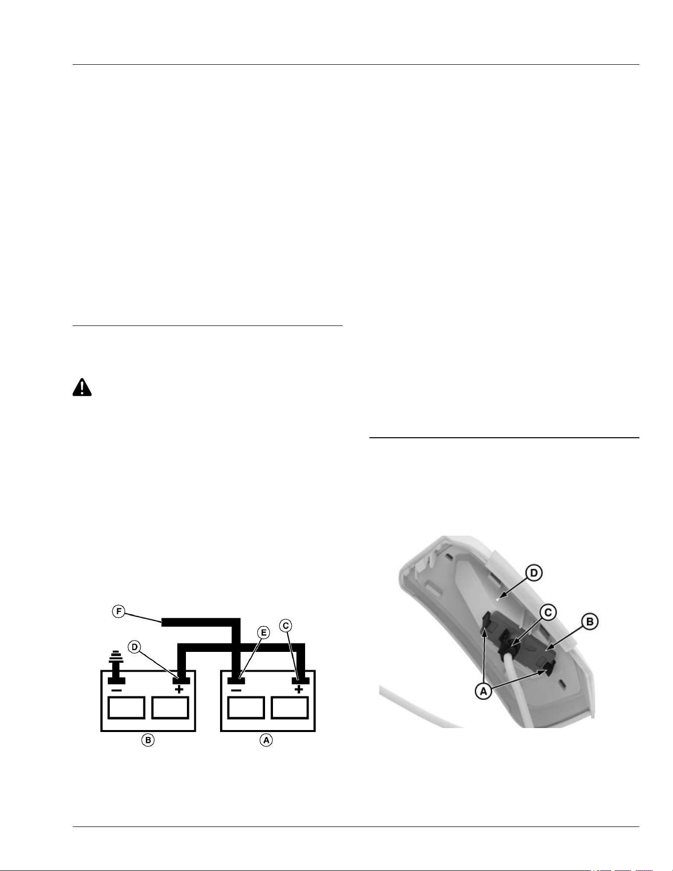
Clean Battery and Terminals
1. Park machine safely. (See Parking Safely in the
Safety section.)
2. Disconnect and remove battery.
3. Wash battery with solution of four tablespoons of
baking soda to one gallon of water. Be careful not to
get the soda solution into the cells.
4. Rinse the battery with plain water and dry.
5. Clean terminals and battery cable ends with wire
brush until bright.
6. Install battery.
7. Attach cables to battery terminals, beginning with the
positive cable, using washers and nuts.
8. Apply spray lubricant to terminal to prevent
corrosion.
MP47322,00F4671-19-17AUG23
Use Booster Battery
CAUTION: Avoid injury! The battery produces a
ammable and explosive gas.
To prevent the battery from exploding:
● Do not smoke or have open ame near
battery.
● Wear eye protection and gloves.
● Do not jump-start or charge a frozen battery.
Warm battery to:
Specication
Battery—Temperature. . . . . . . . . . . . . . . . . . . . . . . . . 16°C (60°F)
● Do not connect the negative (-) booster cable
to the negative (-) terminal of the discharged
battery. Connect at a good ground location
away from the discharged battery.
MXAL42872—UN—09APR13
A—Booster Battery
B—Disabled Vehicle Battery
C—Positive (+) Post
D—Positive (+) Post
E—Negative (-) Post
F—Negative (-) Booster Cable End
1. Connect positive (+) booster cable to booster battery
(A) positive (+) post (C).
2. Connect the other end of positive (+) booster cable to
the disabled vehicle battery (B) positive (+) post (D).
3. Connect negative (–) booster cable to booster
battery negative (–) post (E).
IMPORTANT: Avoid damage! Electric charges from
the booster battery damages machine
components. Do not install negative booster
cable to machine frame. Install only to the
engine block.
Install negative booster cable away from
moving parts in the engine compartment, such
as belts and fan blades.
4. Connect the other end (F) of negative (–) booster
cable to a metal part of the disabled machine engine
block away from battery.
5. Start the engine of the disabled machine and run
machine for several minutes.
6. Carefully disconnect the booster cables in the exact
reverse order: negative cable rst and then the
positive cable.
MP47322,00F4672-19-10AUG23
Replacing Headlight
1. Park the machine safely. (See "Parking Safely" in the
Safety section.)
2. Lift the hood.
MX663343—UN—06MAY25
3. Spread the tabs (A).
4. Remove the LED light (B) from the headlight
assembly (D).
5. Disconnect the connector (C) from the LED light (B).
Service Electrical
60-2
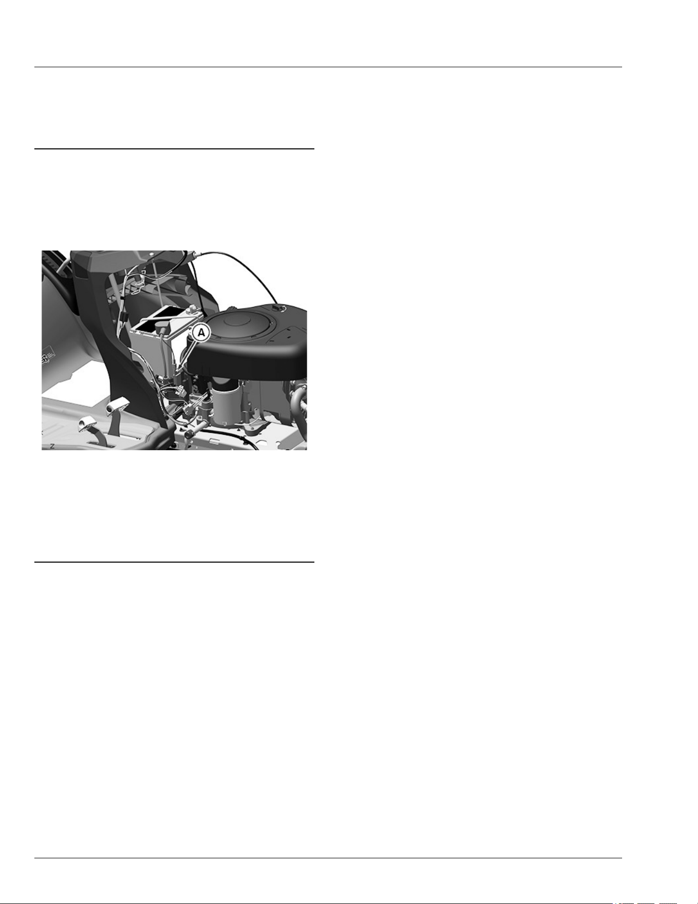
6. Connect the new LED light to the connector.
7. Install the new LED light into headlight assembly (D).
8. Lower the hood.
SDHTXN6,1745842272398-19-06MAY25
Replacing Fuse
1. Park machine safely. (See Parking Safely in the
Safety section.)
2. Lift hood.
APY36188—UN—10JUL20
3. Pull defective fuse (A) out of socket.
4. Check metal clip in fuse window and discard fuse if
clip is broken.
5. Push new 20 A fuse into socket.
6. Lower hood.
MG39705,00004B5-19-03JUL20
Service Electrical
60-3
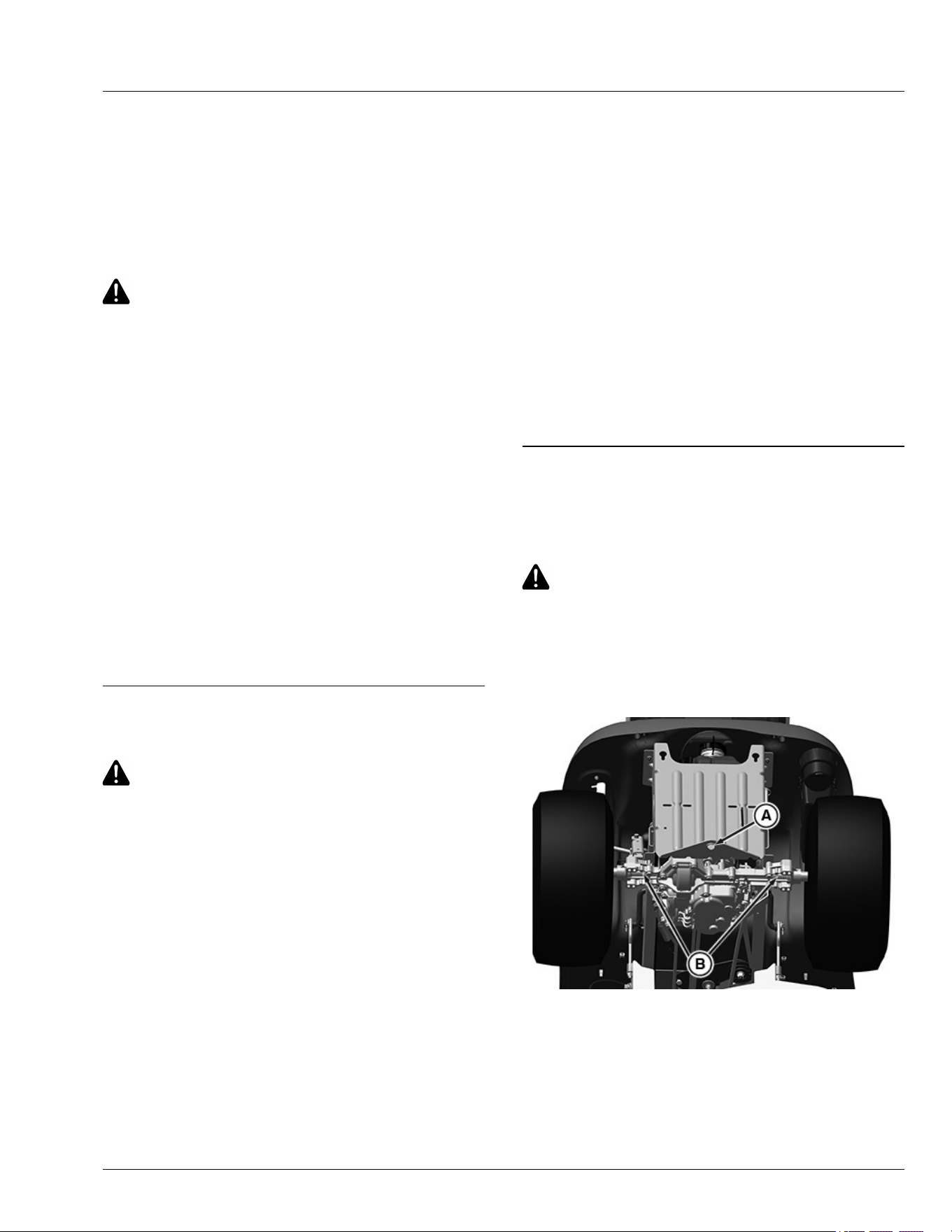
Gasoline Fuel for 4-Cycle Engines
Use unleaded gasoline with a minimum octane rating of
87 AKI (anti-knock index) or 90 RON (research octane
number). Gasoline fuels specied to EN 228 or ASTM
D4814 are recommended.
Fuel blends of unleaded gasoline with a maximum 10%
ethanol or 15% MTBE (methyl tertiary-butyl ether) are
also acceptable.
CAUTION: Reduce the risk of re. Handle fuel
carefully. DO NOT ll the fuel tank when the
engine is running or hot. Stop engine and allow
it to cool for several minutes before lling fuel
tank. Fill fuel tank only to the bottom of the ller
neck.
Refuel outdoors. DO NOT smoke while you ll
the fuel tank or service the fuel system.
Store fuel in properly identied polyethylene
containers.
When storing fuel, add John Deere Gasoline
Conditioner and Stabilizer (or equivalent) at the
specied concentration.
IMPORTANT: DO NOT use methanol or fuel blends
that contain methanol.
Avoid spilling fuel. Gasoline can damage plastic
and painted surfaces.
DO NOT mix oil with gasoline.
DX,FUEL2-19-15MAY13
Fill Fuel Tank
CAUTION: Avoid injury! Fuel vapors are
explosive and ammable:
● Shut engine o before lling fuel tank.
● Allow engine to cool before refueling.
● Do not smoke while handling fuel.
● Keep fuel away from ames or sparks.
● Fill fuel tank outdoors or in ventilated area.
● Clean up spilled fuel immediately.
● Prevent static electric discharge by using a
clean, approved, non metal container.
IMPORTANT: Avoid damage! Dirt and water in fuel
causes engine damage:
● Clean dirt and debris from the fuel tank
opening.
● Use clean, fresh, stabilized fuel.
● Fill the fuel tank at the end of operation each
day to prevent condensation and freezing
during cold weather.
● If using a funnel, make sure it is plastic and
has no screen or lter.
1. Park machine safely. (See Parking Safely in the
Safety section.)
2. Allow engine to cool.
3. Remove any debris from area around fuel tank cap.
4. Remove fuel tank cap slowly to allow any pressure
built up in tank to escape.
5. Fill fuel tank only to bottom of ller neck. Do not
overll.
NOTE: On some models, the fuel tank cap will click
when it is tight.
6. Install fuel tank cap and turn cap until it is tight.
MP47322,00F4675-19-10AUG23
Lifting Machine
1. Park machine safely. (See Parking Safely in the
Safety section.)
CAUTION: Avoid injury! The machine can fall or
slip from an unsafe lifting device or supports.
● Use a safe lifting device rated for the load to
be lifted.
● Lower machine onto jackstands or other
stable supports and block wheels before
servicing.
APY36180—UN—10JUL20
2. Safely lift rear of the machine at the machine frame
point (A). Place jackstands or other stable supports
onto transaxle locations (B) where mounting bolts for
frame come through.
3. If only lifting rear of machine, block front wheels
remaining on ground to avoid movement of the
machine.
Service Miscellaneous
65-1
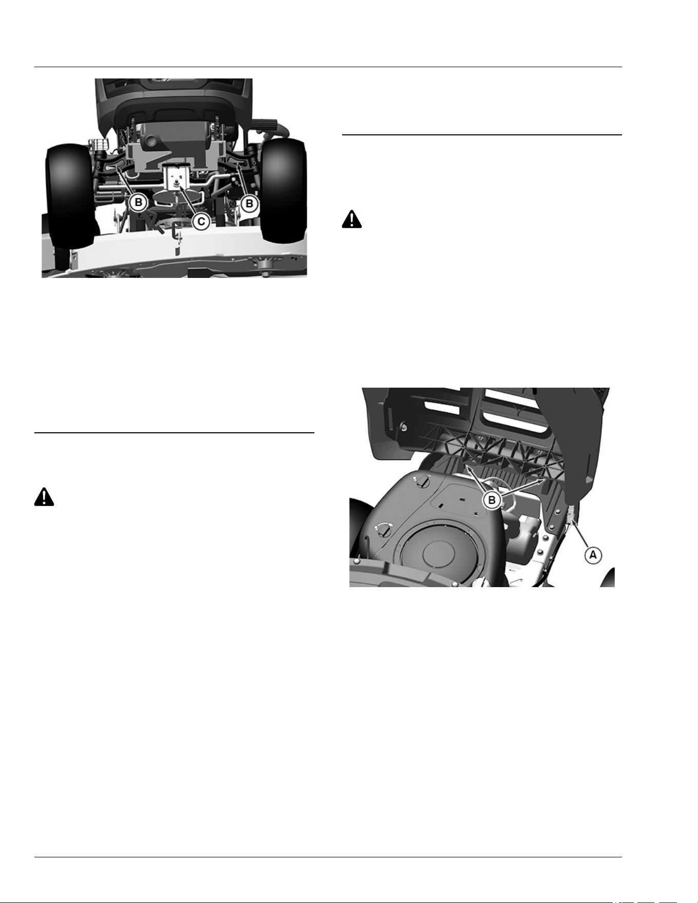
APY36181—UN—10JUL20
4. Safely lift front of the machine at the machine frame
point (C). Place jackstands or other stable supports
under the frame on each side at location (B).
5. If only lifting front of machine, block rear wheels
remaining on ground to avoid movement of the
machine.
6. To lower the machine, lift front and/or rear of
machine, and remove jackstands or supports. Lower
machine.
MG39705,00004ED-19-28JUL20
Checking Tire Pressure
CAUTION: Avoid injury! Explosive separation of
tire and rim parts is possible when they are
serviced incorrectly:
● Do not attempt to mount a tire without the
proper equipment and experience to perform
the job.
● Make sure that all tires are inated to the
recommended pressure, especially when
operating on slopes. Low pressure can
cause machine to become unstable on
slopes.
● Do not weld or heat a wheel and tire
assembly. Heat can cause an increase in air
pressure resulting in an explosion. Welding
can structurally weaken or deform the wheel.
● Do not stand in front or over the tire
assembly when inating. Use a clip-on chuck
and extension hose long enough to allow
you to stand to one side.
1. Check tires for damage.
2. Check tire pressure with an accurate low-pressure
gauge.
3. A lower pressure will improve traction and
performance depending on turf conditions or if
transport areas have steep inclines.
4. Add or remove air to meet specied tire pressure.
(See Specications section for recommended tire
pressures.)
MP47322,00F4677-19-10JUN20
Removing and Installing Hood
Removing
CAUTION: Avoid injury! Touching hot surfaces
can burn skin. The engine, components, and
uids are hot if the engine has been running.
Allow the engine to cool before servicing or
working near the engine and components.
IMPORTANT: Avoid damage! Do not operate
machine with hood open. Hood must be closed
for proper engine cooling and exhaust.
1. Park machine safely. (See Parking Safely in the
Safety section.)
2. Let engine cool.
APY36182—UN—10JUL20
3. Open hood.
4. Disconnect wiring harness (A).
Service Miscellaneous
65-2
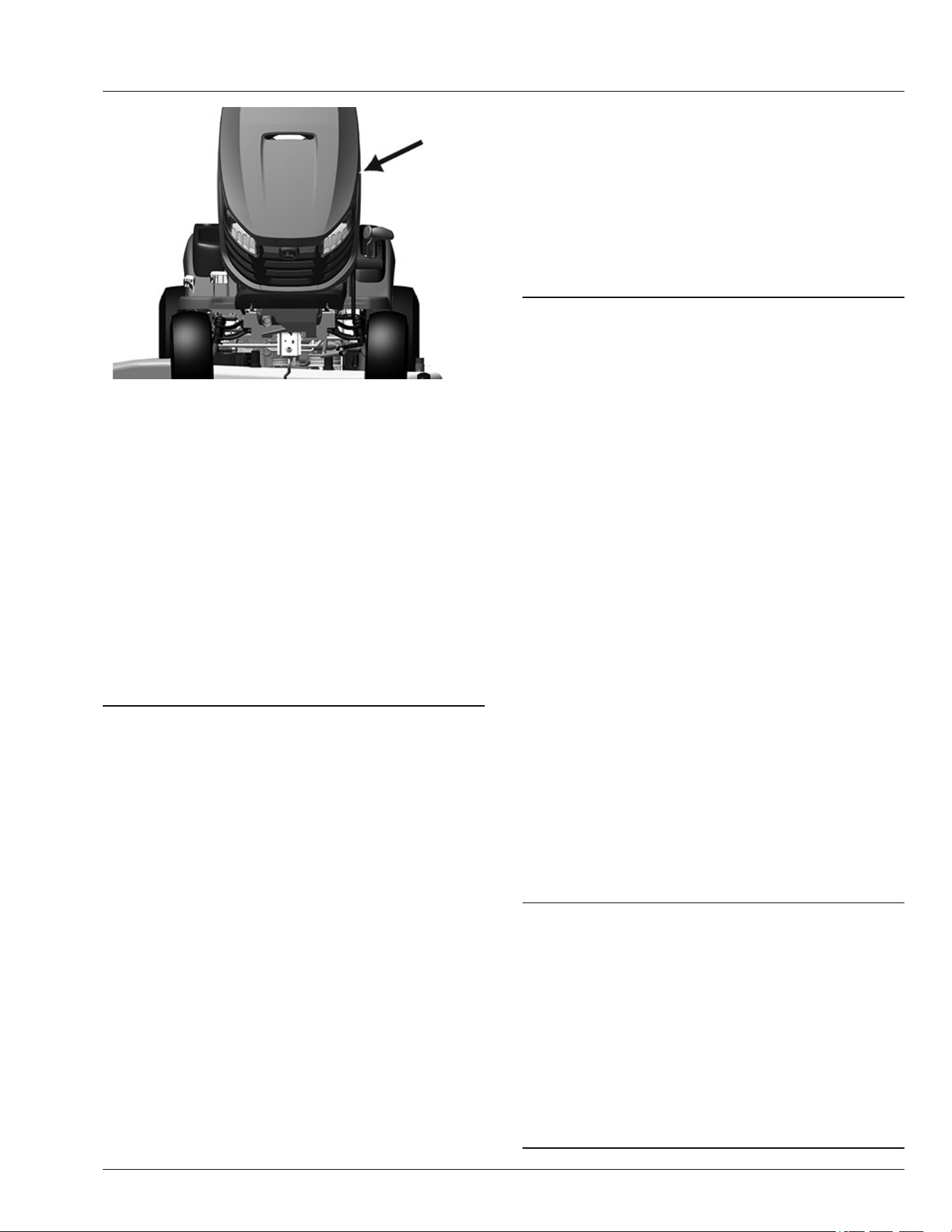
APY36183—UN—10JUL20
5. Apply pressure to the pointed position on the left side
of hood and slowly lower hood. Left side pivot will
release after rotating closed approximately 45°.
Once left side pivot releases, slide out right side
pivot. Lower hood slightly and lift hood from brackets
(B).
Installing
1. Slide right side hood pivot into the tractor bracket
with hood in open position (left side pivot slides into
place as hood closes) and slowly close hood.
2. Open hood.
3. Connect wiring harness. Verify that wiring harness is
properly retained.
4. Close hood.
MG39705,00004EF-19-28JUL20
Cleaning Plastic Surfaces
IMPORTANT: Avoid damage! Improper care of
machine plastic surfaces can damage that
surface:
● Do not wipe plastic surfaces when they are
dry. Dry wiping results in minor surface
scratches.
● Use a soft, clean cloth (bath towel, diaper,
automotive mitt.)
● Do not use abrasive materials, such as
polishing compounds, on plastic surfaces.
1. Rinse hood and entire machine with clean water to
remove dirt and dust that may scratch the surface.
2. Wash surface with clean water and a mild liquid
automotive washing soap.
IMPORTANT: Avoid damage! Insect repellent spray
may damage plastic and painted surfaces. Do
not spray insect repellent near machine.
3. Dry thoroughly to avoid water spots.
4. Wax the surface with a liquid automotive wax. Use
products that specically say “contains no
abrasives.”
IMPORTANT: Avoid damage! Do not use a power
buer to remove wax.
5. Bu applied wax by hand using a clean, soft cloth.
SR99263,00002B3-19-06APR20
Cleaning and Repairing Metal Surfaces
Cleaning:
Follow automotive practices to care for your vehicle’s
painted metal surfaces. Use a high-quality automotive
wax regularly to maintain the factory look of your
vehicle’s painted surfaces.
Repairing Minor Scratches (surface scratch):
1. Clean area to be repaired thoroughly.
IMPORTANT: Avoid damage! Do not use rubbing
compound on painted surfaces.
2. Use automotive polishing compound to remove
surface scratches.
3. Apply wax to entire surface.
Repairing Deep Scratches (bare metal or primer
showing):
1. Clean area to be repaired with rubbing alcohol or
mineral spirits.
2. Use paint stick with factory-matched colors available
from your service provider to ll scratches. Follow
directions included on paint stick for use and for
drying.
3. Smooth out surface using an automotive polishing
compound. Do not use power buer.
4. Apply wax to surface.
MP47322,00F467A-19-16JUL25
Avoid Damage to Plastic and Painted
Surfaces
● Do not wipe plastic parts until they are rinsed rst.
Using a dry cloth causes scratches.
● Insect repellent spray damages plastic and painted
surfaces. Do not spray insect repellent near
machine.
● Be careful not to spill fuel on the machine. Fuel
damages surfaces. Wipe up spilled fuel immediately.
MP47322,00F4630-19-02DEC22
Service Miscellaneous
65-3
Removing and Installing Front Wheel
Assembly
Removing:
1. Park machine safely. (See Parking Safely in the
Safety section.)
CAUTION: Avoid injury! The machine can fall or
slip from an unsafe lifting device or supports.
● Use a safe lifting device rated for the load to
be lifted.
● Lower machine onto jackstands or other
stable supports and block wheels before
servicing.
IMPORTANT: Avoid damage! Place jackstands
under frame, not under transmission or engine,
when raising or supporting machine.
APY36184—UN—10JUL20
2. Safely lift and support machine. Place safe lifting
device under end of front hanger bracket at location
(A), and place jackstands or other stable supports
under frame on each side at location (B). Block
wheels remaining on the ground to prevent machine
movement.
GXAL42052—UN—04MAR13
3. Remove plastic cap (C) from end of wheel hub.
CAUTION: Avoid injury! Components are
installed under spring tension. Wear eye
protection and use proper tools when installing
and removing components with spring tension.
GXAL42053—UN—04MAR13
4. Remove snap ring (D) from end of axle.
5. Remove washer (E) and wheel from axle.
CAUTION: Avoid injury! Explosive separation of
tire and rim parts is possible when they are
serviced incorrectly:
● Do not attempt to mount a tire without the
proper equipment and experience to perform
the job.
6. Take wheel assembly to a John Deere dealer or other
service providerfor repairs.
Installing
1. Grease spindles and wheel hub grease ttings with
specied grease.
2. Install wheel and washer (E) on axle.
3. Install snap ring (D).
4. Install plastic cap (C).
5. Safely remove jackstands and lower machine.
SR99263,00002B1-19-17OCT25
Removing and Installing Rear Wheel
Assembly
Removing
1. Park machine safely. (See Parking Safely in the
Safety section.)
CAUTION: Avoid injury! The machine can fall or
slip from an unsafe lifting device or supports.
● Use a safe lifting device rated for the load to
be lifted.
● Lower machine onto jackstands or other
Service Miscellaneous
65-4
stable supports and block wheels before
servicing.
IMPORTANT: Avoid damage! Place jackstands
under frame, not under transmission or engine,
when raising or supporting machine.
APY36180—UN—10JUL20
2. Safely lift and support machine. Place safe lifting
device under transmission centered under machine
frame point (A). Place jackstands or other stable
supports on each side (B) where mounting bolts for
frame come through. Block wheels remaining on the
ground to prevent machine movement.
APY36185—UN—10JUL20
3. Remove plastic cap (C), snap ring (D), and washer
(E).
4. Remove wheel.
IMPORTANT: Avoid damage! Do not lose the shaft
key. Key must be installed for wheels to rotate
and tractor to move.
5. Remove shaft key (F) (shown on end of transmission
shaft), two washers (G), except for model S100, and
spacer (H).
CAUTION: Avoid injury! Explosive separation of
tire and rim parts is possible when they are
serviced incorrectly:
● Do not attempt to mount a tire without the
proper equipment and experience to perform
the job.
6. Take wheel assembly to a John Deere dealer or other
service provider for repairs.
Installing
IMPORTANT: Avoid damage! Do not lose the shaft
key. Key must be installed for wheels to rotate
and tractor to move.
NOTE: Rear wheels are installed with valves to the
outside.
1. Install two washers (G), except on model S100,
spacer (H), and shaft key (F).
2. Install rear wheel, washer (E), snap ring (D), and
plastic cap (C).
3. Safely remove jackstands and lower machine.
SR99263,00002F1-19-17OCT25
Service Miscellaneous
65-5

Using Troubleshoot Chart
If you are experiencing a problem that is not listed in this chart, see
your Technical Manual, dealer, or other service provider for service.
MP47322,00F467B-19-17OCT25
Engine
IF CHECK
Poor Engine Performance Dirt in fuel system or fuel is old.
Replace fuel with fresh stabilized
fuel. Obtain fuel from another
supplier before suspecting
machine problems. Suppliers
blend fuels dierently and
changing suppliers will generally
solve any performance
problems.
Fuel blended with alcohol or
ether may contribute to
performance problems by
causing gum and varnish
deposits, especially if fuel is
stored for several weeks or more.
Obtain fresh fuel.
Engine Will Not Start Brake pedal not depressed.
Mower is engaged.
Spark plug wire is loose or
disconnected.
Improper fuel.
Transmission is in reverse.
Plugged fuel lter.
Defective safety switch.
Electrical problem - See
Electrical Troubleshooting
Section
Engine Is Hard To Start Choke cable not adjusted
properly.
Plugged fuel lter.
Faulty spark plug.
Stale or improper fuel.
Loose or corroded electrical
connections.
Improper engine oil viscosity.
Engine Runs Unevenly Cooling ns plugged.
Loose electrical connections.
Choke or throttle cable sticking.
Fuel line or fuel lter plugged.
Stale or dirty fuel.
Improper fuel.
Air cleaner element plugged.
Engine Misses Under Load Faulty spark plug.
Stale or dirty fuel.
Plugged fuel lter.
Engine Vapor Locks Fuel tank vent plugged.
Dirt in fuel lter.
Cooling ns plugged.
Loose hose connection at fuel
lter or fuel pump.
Engine Overheats Engine air intake screen
plugged.
Cooling ns plugged.
Engine oil low or too high.
Engine operated too long at a
slow idle speed.
IF CHECK
Engine Will Not Idle Spark plug not gapped correctly.
Faulty spark plug.
Operator raising o the seat.
Engine Knocks Stale or low octane fuel.
Engine overloaded.
Low engine speed.
Oil level low.
Engine Stops Or Misses When
Operating On Hillsides
Fuel tank less than half full of
fuel.
Operator raising o of the seat.
Engine Backres Faulty spark plug.
Operator raising o of the seat.
Engine Loses Power Engine overheating.
Too much oil in engine.
Dirty air cleaner.
Faulty spark plug.
Travel speed is too fast for
conditions.
Improper fuel.
Excessive Fuel Consumption Choke is not fully open.
Black Exhaust Smoke Air lter is dirty or oil soaked.
Choke partially engaged.
Engine Stops When REVERSE
Foot Pedal Is Depressed And
Attachment Is Engaged
(Hydrostatic)
Normal condition. (See Using
Reverse Implement Option in the
OPERATING section.)
Engine Stops When Automatic
Shift Lever Is Moved To The R
(REVERSE) Position and
Attachment Is Engaged
(Automatic)
Normal condition. (See Using
Reverse Implement Option in the
OPERATING section.)
RM87422,00002A4-19-06JUL15
Electrical
IF CHECK
Starter Does Not Work Or Will
Not Turn Engine
Brake pedal is not depressed.
Mower is engaged.
Battery terminals are corroded.
Battery not charged.
Transmission is in reverse.
Blown fuse.
Battery Will Not Charge Dead cell in the battery.
Battery cables and terminals are
dirty.
Low engine speed or excessive
idling.
Lights Do Not Work Light plug disconnected.
Loose or burned out bulb.
The fuel level indicator ashes
"E33" intermittently or shows full
bars constantly when fuel tank is
not full
Check the fuel sender connector
located beneath the seat for full
and proper connection. If
connections are good but the
problem persists, contact your
John Deere Dealer or other
service provider.
MG39705,00004DB-19-29JUL25
Troubleshooting
70-1

Tractor
IF CHECK
Tractor Vibrates Too Much Or
Rattles Excessively
Attachment drive belts worn or
damaged.
Traction drive belt damaged or
worn.
Dirt on drive sheaves.
Blades bent or out of balance.
Tractor Will Not Move With
Engine Running
Parking brake locked.
Bypass rod is pulled out.
OUO1023,00001EB-19-19JUN15
Mower
IF CHECK
Discharge Chute Plugged Travel speed too fast.
Grass too long.
Grass too wet.
Engine rpm not at wide open
throttle.
Restricted air ow.
Belt installed incorrectly.
Patches Of Grass Uncut Travel speed too fast.
Engine rpm not at wide open
throttle.
Mower deck needs cleaning.
Belt Slipping Debris in sheaves.
Worn belt.
Belt tension is incorrect.
Too Much Vibration Debris on mower deck or in
sheaves.
Damaged drive belt.
Damaged sheaves or sheaves
out of alignment.
Blades out of balance.
Blades Scalping Grass Cutting too low.
Mower wheels not adjusted
correctly.
Turning speed too fast.
Ridges in terrain.
Rough or uneven terrain.
Low tire pressure.
Mower Loads Down Tractor Engine rpm too low.
Travel speed too fast.
Debris wrapped around mower
spindles.
Uneven Cut Mower deck not leveled properly.
Travel speed too fast.
Blades dull.
Mower wheels not adjusted
correctly.
Tire pressure unequal.
Mower (Or Other Attachment)
Stops When Vehicle Is Operated
in REVERSE
Normal condition. (See Using
Reverse Implement Option in the
OPERATING section.)
OUO1023,00001EC-19-19JUN15
Troubleshooting
70-2

Storing Safety
CAUTION: Avoid injury! Fuel vapors are
explosive and ammable.
Engine exhaust fumes contain carbon
monoxide and cause serious illness or death:
● Run the engine only long enough to move
the machine to or from storage.
● If a machine is stored before allowing it to
cool, machine res and structure res can
occur. Fires can occur if debris is not
removed from around the engine and muer,
or if stored near combustible materials.
● Do not store vehicle with fuel in the tank
inside a building where fumes reach an open
ame or spark.
● Allow the engine to cool before storing the
machine in any enclosure.
MP47322,00F4680-19-06MAY15
Preparing Machine for Storage
1. Repair any worn or damaged parts. Replace parts if
necessary. Tighten loose hardware.
2. To prevent rust, repair scratched or chipped metal
surfaces.
3. Remove grass and debris from machine.
4. Clean under the rotary deck and remove grass and
debris from inside chute and bagger, if applicable.
5. Wash the machine and apply wax to metal and
plastic surfaces.
6. To dry belts and pulleys, run machine for ve
minutes.
7. To prevent rust, apply light coat of engine oil on pivot
and wear points.
8. Lubricate grease points and check tire pressure.
MP47322,00F4681-19-13JUL16
Preparing Fuel and Engine For Storage
Fuel:
If you have been using “Stabilized Fuel,” add stabilized
fuel to tank until the tank is full.
NOTE: Filling the fuel tank reduces the amount of air in
the fuel tank and helps reduce deterioration of fuel.
If you are not using “Stabilized Fuel”:
1. Park machine safely in a well-ventilated area. (See
Parking Safely in the Safety section.)
NOTE: Try to anticipate the last time the machine will be
used for the season so very little fuel is left in the
fuel tank.
2. Turn on engine and allow to run until it runs out of
fuel.
3. For machines equipped with key switch, turn key to
o position.
IMPORTANT: Avoid damage! Stale fuel can produce
varnish and plug carburetor or injector
components and aect engine performance.
● Add fuel conditioner or stabilizer to fresh fuel
before lling tank.
4. Mix fresh fuel and fuel stabilizer in separate
container. Follow stabilizer instructions for mixing.
5. Fill fuel tank with stabilized fuel.
6. Run engine for a few minutes to allow fuel mixture to
circulate through carburetor on gas engine or fuel
injectors on diesel engine.
Engine:
Engine storage procedure should be used when vehicle
is not to be used for longer than 60 days.
1. Change engine oil and lter.
2. Service air lter if necessary.
3. Clean debris from engine air intake screen.
4. On gas engines:
● Remove spark plugs. Put 30 mL (1 oz) of clean
engine oil in cylinders.
● Install spark plugs, but do not connect spark plug
wires.
● Crank the engine 5 or 6 times to allow oil to be
distributed.
5. Clean the engine and engine compartment.
6. Remove battery.
7. Clean the battery and battery posts. Check the
electrolyte level if your battery is not maintenance
free.
8. Close fuel shuto valve if your machine is equipped.
9. Store the battery in a cool, dry place where it will not
freeze.
NOTE: The stored battery should be recharged every 90
days.
10. Charge the battery.
IMPORTANT: Avoid damage! Prolonged exposure to
sunlight could damage surfaces. Store machine
inside or use a cover if stored outside.
Storage
75-1

11. Store the vehicle in a dry, protected place. If vehicle
is stored outside, put a waterproof cover over it.
RM87422,00007C9-19-19JUL17
Removing Machine From Storage
1. Check tire pressure.
2. Check engine oil level.
3. Check battery electrolyte level if your battery is not
maintenance free. Charge battery if necessary.
4. Install battery.
5. On gas engines: check spark plug gap. Install and
tighten plugs to specied torque.
6. Lubricate all grease points.
7. Open fuel shut-o valve if your machine is equipped.
8. Run the engine 5 minutes without the mower or any
attachments running to allow oil to be distributed
throughout engine.
9. Be sure all shields and guards or deectors are in
place.
MP47322,00F4683-19-17FEB23
Storage
75-2

Model S100
Engine Model . . . . . . . . . . . . . . . . . . . . . . . Briggs & Stratton 31
Power Rating Information . . . . . . . . . . www.briggsandstratton.com/
Displacement. . . . . . . . . . . . . . . . . . . . . . . . . . . 500 cc (30.5 in
3
)
Spark Plug Gap . . . . . . . . . . . . . . . . . . . . . . . 0.76 mm (0.030 in)
Spark Plug Torque . . . . . . . . . . . . . . . . . . . . . . . 20 N·m (15 lb·ft)
Cylinders. . . . . . . . . . . . . . . . . . . . . . . . . . . . . . . . . . . . . . Single
Oil Filter . . . . . . . . . . . . . . . . . . . . . . . . . . . . . . . . . . . . Standard
Air Filter . . . . . . . . . . . . . . . . . . . . . . . . . . . . . . . . . . . .Cartridge
Transmission . . . . . . . . . . . . . . . . . . . . . . . . . . . . . . . Hydrostatic
Transaxle Model . . . . . . . . . . . . . . . . . . . . . . . . . . . . . . . . TL200
Travel Speed - Forward . . . . . . . . . . . . 0—8.9 km/h (0—5.5 mph)
Travel Speed - Reverse . . . . . . . . . . . . 0—4.8 km/h (0—3.0 mph)
SDHTXN6,1748836442854-19-01JUN25
Model S110
Engine Model . . . . . . . . . . . . . . . . . . . . . . . Briggs & Stratton 33
Power Rating Information . . . . . . . . . . www.briggsandstratton.com/
Displacement. . . . . . . . . . . . . . . . . . . . . . . . . . . . 540 cc (33 in
3
)
Spark Plug Gap . . . . . . . . . . . . . . . . . . . . . . . 0.76 mm (0.030 in)
Spark Plug Torque . . . . . . . . . . . . . . . . . . . . . . . 20 N·m (15 lb·ft)
Cylinders. . . . . . . . . . . . . . . . . . . . . . . . . . . . . . . . . . . . . . Single
Oil Filter . . . . . . . . . . . . . . . . . . . . . . . . . . . . . . . . . . . . Standard
Air Filter . . . . . . . . . . . . . . . . . . . . . . . . . . . . . . . . . . . .Cartridge
Transmission . . . . . . . . . . . . . . . . . . . . . . . . . . . . . . . Hydrostatic
Transaxle Model . . . . . . . . . . . . . . . . . . . . . . . . . . . . . . . . TL200
Travel Speed - Forward . . . . . . . . . . . . 0—8.9 km/h (0—5.5 mph)
Travel Speed - Reverse . . . . . . . . . . . . 0—4.8 km/h (0—3.0 mph)
SDHTXN6,1748836456580-19-01JUN25
Models S120, S130, S140, and S160
Engine Model . . . . . . . . . . . . . . . . . . . . . . . Briggs & Stratton 44
Power Rating Information . . . . . . . . . . www.briggsandstratton.com/
Displacement. . . . . . . . . . . . . . . . . . . . . . . . . . . 724 cc (44.2 in
3
)
Spark Plug Gap . . . . . . . . . . . . . . . . . . . . . . . 0.76 mm (0.030 in)
Spark Plug Torque . . . . . . . . . . . . . . . . . . . . . . . 20 N·m (15 lb·ft)
Cylinders. . . . . . . . . . . . . . . . . . . . . . . . . . . . . . . . . . . . . . . Twin
Oil Filter (If Equipped) . . John Deere Easy Change 30-Second Oil
Change System
Air Filter . . . . . . . . . . . . . . . . . . . . . . . . . . . . . . . . . . . .Cartridge
Transmission . . . . . . . . . . . . . . . . . . . . . . . . . . . . . . . Hydrostatic
Transaxle Model . . . . . . . . . . . . . . . . . . . . . . . . . . . . . . . . TL200
Travel Speed - Forward . . . . . . . . . . . . 0—8.9 km/h (0—5.5 mph)
Travel Speed - Reverse . . . . . . . . . . . . 0—4.8 km/h (0—3.0 mph)
SDHTXN6,1748836490808-19-01JUN25
Models S170 and S180
Engine Model . . . . . . . . . . . . . . . . . . . . . . . Briggs & Stratton 44
Power Rating Information . . . . . . . . . . www.briggsandstratton.com/
Displacement. . . . . . . . . . . . . . . . . . . . . . . . . . . 724 cc (44.2 in
3
)
Spark Plug Gap . . . . . . . . . . . . . . . . . . . . . . . 0.76 mm (0.030 in)
Spark Plug Torque . . . . . . . . . . . . . . . . . . . . . . . 20 N·m (15 lb·ft)
Cylinders. . . . . . . . . . . . . . . . . . . . . . . . . . . . . . . . . . . . . . . Twin
Oil Filter John Deere Easy Change 30-Second Oil Change System
Air Filter . . . . . . . . . . . . . . . . . . . . . . . . . . . . . . . . . . . .Cartridge
Transmission . . . . . . . . . . . . . . . . . . . . . . . . . . . . . . . Hydrostatic
Transaxle Model . . . . . . . . . . . . . . . . . . . . . . . .Tu Torq HD K46
Travel Speed - Forward . . . . . . . . . . . . 0—8.9 km/h (0—5.5 mph)
Travel Speed - Reverse . . . . . . . . . . . . 0—4.8 km/h (0—3.0 mph)
SDHTXN6,1748836510499-19-01JUN25
Electrical System
Charging System . . . . . . . . . . . . . . . . . . . . . . . . Regulated Circuit
Charging System Capacity (S100, S110, S120, S130, and S140) 9
Amp
Charging System Capacity (S160, S170, and S180). . . . . .16 Amp
Battery Voltage . . . . . . . . . . . . . . . . . . . . . . . . . . . . . . . 12 Volts
Battery Type . . . . . . . . . . . . . . . . . . . . . . . . . . . . . BCI Group U1
SR99263,0000339-19-12MAY20
Fuel System (All Models)
Fuel Types (Recommended):
. . . . . . . . . . . . . . . . . . . Regular Grade 87 Octane Unleaded Fuel
. . . . . . . . . . . . . . . . . . . . . . . . Ethanol Blended Fuel (Up to 10%)
. . . . . . . . . . . . . . . . . . . . . MTBE Reformulated Fuel (Up to 15%)
OUO1023,00001F8-19-01MAR13
Tires
Models S100, S110, S120, and S140
Size (Front) . . . . . . . . . . . . . . . . . . . . . . . . . . . . . . . 15 x 6.00 - 6
Size (Rear) . . . . . . . . . . . . . . . . . . . . . . . . . . . . . . . . 20 x 8.0 - 8
Tire Pressure (Front) . . . . . . . . . . . . . . . . . . . . . . 97 kPa (14 psi)
Tire Pressure (Rear) . . . . . . . . . . . . . . . . . . . . . . 69 kPa (10 psi)
Models S130 and S160
Size (Front) . . . . . . . . . . . . . . . . . . . . . . . . . . . . . . . 15 x 6.00 - 6
Size (Rear) . . . . . . . . . . . . . . . . . . . . . . . . . . . . . . . 20 x 10.0 - 8
Tire Pressure (Front) . . . . . . . . . . . . . . . . . . . . . . 97 kPa (14 psi)
Tire Pressure (Rear) . . . . . . . . . . . . . . . . . . . . . . 69 kPa (10 psi)
Models S170 and S180
Size (Front) . . . . . . . . . . . . . . . . . . . . . . . . . . . . . . . . 16 x 6.5 - 8
Size (Rear) . . . . . . . . . . . . . . . . . . . . . . . . . . . . . . . 22 x 9.5 - 12
Specications
80-1

Tire Pressure (Front) . . . . . . . . . . . . . . . . . . . . . . 83 kPa (12 psi)
Tire Pressure (Rear) . . . . . . . . . . . . . . . . . . . . . . 83 kPa (12 psi)
(Tire pressure information is also located on the sidewalls of the
tires)
SR99263,000033A-19-07JUN21
Capacities
Models S100 and S110
Crankcase, with Oil Filter . . . . . . . . . . . . . . . . . . . . . 1.4 L (1.5 qt)
Models S140
Crankcase, with Oil Filter . . . . . . . . . . . . . . . . . . . . . 1.9 L (2.0 qt)
Models S120, S130, S160, S170, and S180
Crankcase, with Easy Change™ 30-Second Oil Change
System . . . . . . . . . . . . . . . . . . . . . . . . . . . . . . . . . . 2.6 L (2.8 qt)
Fuel Tank (All Models) . . . . . . . . . . . . . . . . . . . . . . . 9 L (2.4 gal)
Towing Capacity (All Models) . . . . . . . . . . . . . . 226.79 kg (500 lb)
SR99263,000033B-19-07MAY21
Dimensions
Height (S100 and S110) . . . . . . . . . . . . . . . . . . . 108 cm (42.5 in)
Height (S120, S130, and S140) . . . . . . . . . . . . . 113 cm (45.5 in)
Height (S160) . . . . . . . . . . . . . . . . . . . . . . . . . 118 cm (46.46 in)
Height (S170 and S180). . . . . . . . . . . . . . . . . . . 118 cm (46.5 in)
Length (Overall)
(S100, S110, and S120) . . . . . . . . . . . . . . . . . . 175 cm (68.75 in)
Length (Overall) (S130) . . . . . . . . . . . . . . . . . . 186 cm (73.25 in)
Length (Overall) (S140) . . . . . . . . . . . . . . . . . . . 177 cm (69.5 in)
Length (Overall) (S160) . . . . . . . . . . . . . . . . . . . 191 cm (75.2 in)
Length (Overall) (S170 and S180). . . . . . . . . . . . 194 cm (76.5 in)
Width (Mower Deck Chute Down)
(S100, S110, S120, and S130) . . . . . . . . . . . . . . 138 cm (54.4 in)
Width (Mower Deck Chute Down) (S160) . . . . . . . .155 cm (61 in)
Width (Mower Deck Chute Down)
(S140 and S170) . . . . . . . . . . . . . . . . . . . . . . . . . .152 cm (60 in)
Width (Mower Deck Chute Down) (S180) . . . . . . 174 cm (68.5 in)
Weight: S100. . . . . . . . . . . . . . . . . . . . . . . . . . . . 189 kg (415 lb)
Weight: S110 . . . . . . . . . . . . . . . . . . . . . . . . . . . . 193 kg (423 lb)
Weight: S120. . . . . . . . . . . . . . . . . . . . . . . . . . . . 198 kg (436 lb)
Weight: S130. . . . . . . . . . . . . . . . . . . . . . . . . . . . 201 kg (443 lb)
Weight: S140. . . . . . . . . . . . . . . . . . . . . . . . . . . . 218 kg (479 lb)
Weight: S160. . . . . . . . . . . . . . . . . . . . . . . . . . 217.72 kg (480 lb)
Weight: S170. . . . . . . . . . . . . . . . . . . . . . . . . . . . 229 kg (504 lb)
Weight: S180. . . . . . . . . . . . . . . . . . . . . . . . . . . . 241 kg (530 lb)
SR99263,000033C-19-15MAY20
Mower Deck - 107 cm (42 in)
Blades Rotary . . . . . . . . . . . . . . . . . . . . . . . . . . . . . . . . . . . . . 2
Blade Nut Torque (w/5/8 in. Nut) . . . . . . . . . . . . . 88 N•m (65 lb·ft)
Cutting Height (Approximately) . . . . . . . . . . 2.5 -10.2 cm (1 - 4 in)
Cutting Width. . . . . . . . . . . . . . . . . . . . . . . . . . . . .107 cm (42 in)
SR99263,000014D-19-24JUL19
Mower Deck - 122 cm (48 in)
Blades Rotary . . . . . . . . . . . . . . . . . . . . . . . . . . . . . . . . . . . . . 3
Blade Nut Torque (w/5/8 in. Nut) . . . . . . . . . . . . . 88 N•m (65 lb·ft)
Cutting Height (Approximately) . . . . . . . . . . 2.5 -10.2 cm (1 - 4 in)
Cutting Width. . . . . . . . . . . . . . . . . . . . . . . . . . . . .122 cm (48 in)
SR99263,000014E-19-24JUL19
Mower Deck - 137 cm (54 in)
Blades Rotary . . . . . . . . . . . . . . . . . . . . . . . . . . . . . . . . . . . . . 3
Blade Nut Torque (w/5/8 in. Nut) . . . . . . . . . . . . . 88 N•m (65 lb·ft)
Cutting Height (Approximately) . . . . . . . . . . 2.5 -10.2 cm (1 - 4 in)
Cutting Width. . . . . . . . . . . . . . . . . . . . . . . . . . . . .137 cm (54 in)
SR99263,000014F-19-24JUL19
Recommended Lubricants
Engine Oil . . . . . . . . . . . . . . . . . . . . . . . . . . Turf-Gard OR Plus-4
Grease . .Grease-Gard Premium Plus. . John Deere Multi-Purpose
HD Lithium Complex Grease
(Specications and design subject to change without
notice.)
gvg6119,1716186699181-19-20MAY24
Specications
80-2

Product Warranty
John Deere oers a standard warranty on new John
Deere products. For a copy of the product warranty
statement or for details on the warranty terms and
conditions for products purchased in the United States
and Canada, please contact your local John Deere
Dealer or utilize the following resources:
United States
Website:
http://www.deere.com/en_US/services_and_support/
warranty/warranty.page
Toll Free: 1-800-537-8233
Dealer Locator:
http://dealerlocator.deere.com/servlet/country=US
Canada
Website (English):
http://www.deere.ca/en_CA/services_and_support/
service_plans_warranties/service_plans_warranties.
page
Website (French):
http://fr.deere.ca/en_CA/services_and_support/
service_plans_warranties/service_plans_warranties.
page
Toll Free: 1-800-537-8233
Dealer Locator:
http://dealerlocator.deere.com/servlet/country=CA
Emission-related warranties are included in this
Operator’s Manual, and applicable if required by law
or regulation.
For products purchased in a country other than the
United States or Canada, please contact your local
John Deere dealer for assistance.
MP47322,00F4690-19-27FEB24
U.S. EPA Emission Control System
Warranty Statement (O-Road Engine
Equipment)
Your Warranty Rights and Obligations
John Deere and the United States Environmental
Protection Agency are pleased to explain the emission
control system's warranty on your o-road engine
equipment. John Deere must warrant the emission
control system on your o-road engine equipment for
the period listed below provided there has been no
abuse, neglect or improper maintenance of your o-
road engine equipment leading to the failure of the
emission control system.
Manufacturer’s Warranty Coverage
Your evaporative emission control system is warranted
for two years. Your o-road engine is warranted as
follows: If your o-road engine equipment has a Briggs
& Stratton engine, your o-road engine is warranted for
two years. For all other o-road engines referenced in
this Operator's Manual, your o-road engine is
warranted for three years. If any emission-related part
on your o-road equipment is defective, the part will be
repaired or replaced by John Deere or an authorized
John Deere service provider.
Owner’s Warranty Responsibilities
● As the spark ignited o-road engine equipment
owner, you are responsible for the performance of
the required maintenance listed in your Operator’s
Manual. John Deere recommends that you retain all
receipts covering maintenance on your spark ignited
o-road engine equipment, but John Deere cannot
deny warranty coverage solely for lack of receipts or
for your failure to ensure the performance of all
scheduled maintenance.
● As the spark ignited o-road engine equipment
owner, you should however be aware that John
Deere may deny you warranty coverage if your spark
ignited o-road engine equipment or a part has failed
due to abuse, neglect, or improper maintenance or
unapproved modications.
● You are responsible for presenting your spark ignited
o-road engine equipment to a John Deere Turf and
Compact Utility distribution center or service center
as soon as a problem exists. The warranty repairs
shall be completed in a reasonable amount of time,
not to exceed 30 days. If you have a question about
your emission control warranty coverage, your
emission control warranty rights and responsibilities,
how to make an emission control system warranty
claim or how to make arrangements for emission-
related authorized repairs, you should contact your
John Deere Turf and Compact Utility retailer, or the
John Deere Customer Contact Center at 1-800-537-
8233, or email John Deere from
https://www.deere.com/en/our-company/contact-us/.
General Emission Control System Warranty
Coverage
The warranty period begins on the date the spark
ignited o-road engine equipment is delivered to an
ultimate purchaser. John Deere warrants to the ultimate
purchaser and each subsequent purchaser that the
spark ignited o-road engine equipment is:
● Designed, built and equipped so it conforms at the
time of sale to the ultimate purchaser with applicable
U.S. Environmental Protection Agency regulations
under 40 CFR Parts 1054, 1048 and 1060; and,
● Free from defects in materials and workmanship that
causes the failure of a warranted part to conform with
Warranty
85-1

applicable regulations for the emission control
system warranty period provided herein.
● For owners located more than 100 miles from a John
Deere authorized service center, John Deere will pay
either for shipping costs to and from an authorized
service center, provide for a service technician to
come to the owner to make the warranty repair, or
pay for the repair to be made at a local non-
authorized service center. These provisions do not
apply to high-altitude counties within the following
States: Alaska, Hawaii, Arizona, Colorado, Idaho,
Montana, Nebraska, Nevada, New Mexico, Oregon,
Texas, Utah, and Wyoming.
Emission Control System Warranty Interpretation
● Any warranted part that is not scheduled for
replacement as required by the maintenance
instructions in the Operator's Manual is warranted as
provided herein. If any such part fails during the
period of warranty coverage it will be repaired or
replaced by John Deere or an authorized John Deere
service provider. Any such part repaired or replaced
under warranty is warranted for the remaining
warranty period.
● Any warranted part that is scheduled only for regular
inspection in the maintenance instructions in the
Operator’s Manual is warranted as provided herein.
A statement in the Operator’s Manual to the eect of
“repair or replace as necessary” does not reduce the
period of warranty coverage. Any such part repaired
or replaced under warranty is warranted for the
remaining warranty period.
● Any warranted part that is scheduled for replacement
as required maintenance in the Operator's Manual is
warranted for the period of time prior to the rst
scheduled replacement point for that part. If the part
fails prior to the rst scheduled replacement, the part
will be repaired or replaced by John Deere or an
authorized John Deere service provider. Any such
part repaired or replaced under warranty is
warranted for the remainder of the period prior to the
rst scheduled replacement point for the part.
● Repair or replacement of any warranted part under
the warranty will be performed at no charge to the
owner by John Deere or an authorized John Deere
service provider.
● The owner will not be charged for diagnostic labor
which leads to the determination that a warranted
part is defective, provided such work is performed by
John Deere or an authorized John Deere service
provider.
● John Deere or an authorized John Deere service
provider will repair damages to other engine
components proximately caused by a failure under
warranty of any emission-related warranted part.
● Add-on or modied parts that are not exempted by
the California Air Resources Board may not be used.
The use of any non-exempted add-on or modied
parts will be grounds for disallowing a warranty claim.
John Deere or any authorized John Deere service
provider will not be liable to warrant failures of
warranted parts caused by the use of a non-
exempted add-on or modied part.
Emission Control System Warranty Parts List
Coverage under this warranty includes, but is not limited
to, the parts listed below (the emission control system
parts) to the extent these parts were on the o-road
equipment and engine purchased.
Fuel Metering System:
● Carburetor and internal parts (or fuel injection
system)
● Air/fuel ratio feedback and control system
● Cold start enrichment system
Evaporative System:
● Fuel tank, fuel cap and tether
● Fuel hose, line, ttings, clamps
● Fuel pump, fuel shut-o valve
● Fuel vapor hoses, ttings
● Carbon canister
● Rollover/slant valve for fuel vapor control
● Purge and vent line
Air Induction System:
● Air cleaner
● Intake manifold
Ignition System:
● Spark plugs
● Magneto or electronic ignition system
● Spark advance/retard system
● Gaskets
Lubrication System:
● Oil pump and internal parts
Positive Crankcase Ventilation (PCV) System
● PCV Valve
● Oil ller cap
Exhaust System:
● Exhaust manifold
● Catalyst muer
Miscellaneous Items Used in Above Systems
Warranty
85-2

● Valves and Switches: vacuum, temperature, position,
check, time-sensitive
● Electronic controls
● Hoses, belts, connectors and assemblies
Limited Liability
a) The liability of John Deere under this emission control
system warranty is limited solely to the remedying of
defects in materials or workmanship. Except as
otherwise expressly provided herein, this warranty does
not cover inconvenience or loss of use of the o-road
equipment or engine or transportation of the equipment
or engine to or from the John Deere Turf and Compact
Utility retailer or authorized service provider. John Deere
shall not be liable for any other expense, loss, or
damage, whether direct, incidental, consequential
(except as listed above under "coverage") or exemplary
arising in connection with the sale or use of or inability to
use the o-road equipment or engine for any other
purpose.
b) No express emission control system warranty is given
by John Deere with respect to the equipment or engine
except as specically set forth in this document. Any
emission control system warranty implied by law,
including any warranty of merchantability or tness for a
particular purpose, is expressively limited to the
emission control system warranty terms set forth in this
document.
c) No dealer or service provider is authorized to modify
this Federal, California and John Deere Emission
Control System Warranty.
mk71445,1710421168405-19-22MAR24
Tire Warranty
John Deere warranty applies for tires available through
the John Deere parts system. For tires not available
through the John Deere parts system, the tire
manufacturer’s warranty applicable to your machine
may not apply outside the U.S. (See your John Deere
dealer for specic information.)
MX00654,0000314-19-21AUG14
Limited Battery Warranty For Factory
Installed Batteries
NOTE: Applicable in North America only. For complete
machine warranty, reference a copy of the John
Deere warranty statement. Contact your John
Deere dealer to obtain a copy.
TO SECURE WARRANTY SERVICE
The purchaser must request warranty service from a
John Deere dealer authorized to sell John Deere
batteries, and present the battery to the dealer with the
top cover plate codes intact.
FREE REPLACEMENT PERIOD
Any new battery which becomes unserviceable (not
merely discharged) due to defects in material or
workmanship within the FREE REPLACEMENT
PERIOD will be replaced free of charge. Installation
costs will be covered by warranty if the unserviceable
battery was installed by a John Deere factory or dealer
and the replacement battery is installed by a John
Deere dealer.
PRO RATA ADJUSTMENT (batteries with letter code
identication only)
Any new battery which becomes unserviceable (not
merely discharged) due to defects in material or
workmanship within the Pro Rata Warranty Period will
be replaced upon payment of the battery’s current list
price less a pro rata credit for unused months of service.
The applicable adjustment period is determined from
the Warranty Code printed at the top of the battery and
table below. Installation costs are not covered after the
battery warranty period has ended.
THIS WARRANTY DOES NOT COVER
A. Breakage of the container, cover, or terminals.
B. Depreciation or damage caused by lack of
reasonable and necessary maintenance or by improper
maintenance.
C. Transportation, mailing, or service call charges for
warranty service.
D. Batteries that are merely discharged.
LIMITATION OF IMPLIED WARRANTIES AND
PURCHASER’S REMEDIES
To the extent permitted by law, neither John Deere nor
any company aliated with it makes any warranties,
representations, or promises as to the quality,
performance or freedom from defect of the products
covered by this warranty. IMPLIED WARRANTIES OF
MERCHANTABILITY AND FITNESS FOR A
PARTICULAR PURPOSE, TO THE EXTENT
APPLICABLE, SHALL BE LIMITED IN DURATION TO
THE APPLICABLE ADJUSTMENT PERIOD SET
FORTH HERE. THE PURCHASER’S ONLY
REMEDIES IN CONNECTION WITH THE BREACH OR
PERFORMANCE OF ANY WARRANTY ON JOHN
DEERE BATTERIES ARE THOSE SET FORTH HERE.
IN NO EVENT WILL THE DEALER, JOHN DEERE OR
ANY COMPANY AFFILIATED WITH JOHN DEERE BE
LIABLE FOR INCIDENTAL OR CONSEQUENTIAL
DAMAGES. (Note: Some states do not allow limitations
on how long an implied warranty lasts or the exclusion
or limitation of incidental or consequential damages. So
these limitations and exclusions may not apply to you.)
This warranty gives you specic legal rights, and you
may also have some rights which vary from state to
state.
Warranty
85-3

NO DEALER WARRANTY
The selling dealer makes no warranty of its own and the
dealer has no authority to make any representation or
promise on behalf of John Deere, or to modify the terms
or limitations of this warranty in any way.
WARRANTY TERMS TABLE
NOTE: If your battery is not labeled with a warranty
code, it is a warranty code 6.
Warranty Code Free Replacement
Period
Pro Rata Warranty
Period
A 90 Days 40 Months
B 90 Days 36 Months
C 90 Days 24 Months
D 12 Months 48 Months
E 90 Days 12 Months
F 90 Days 60 Months
G 12 Months 60 Months
H 12 Months 60 Months
6 6 Months 0 Months
12 12 Months 0 Months
18 18 Months 0 Months
OUMX068,0000504-19-18OCT24
Warranty
85-4

John Deere Quality
John Deere equipment is more than just a purchase, it’s
an investment in quality. That quality goes beyond our
equipment to your John Deere dealer’s parts and
service support. This support is needed to keep you a
satised customer.
That’s why John Deere has initiated a process to handle
your questions or problems, should they arise. The
following three steps will help guide you through the
process.
Step 1
Refer to your operator’s manual
A. It has many illustrations and detailed information on
the safe and proper operation of your equipment.
B. It gives troubleshooting procedures, and specication
information.
C. It gives ordering information for parts catalogs,
service and technical manuals.
D. If your questions are not answered in the operator’s
manual, then go to Step 2.
Step 2
Contact your dealer
A. Your John Deere dealer has the responsibility,
authority, and ability to answer questions, resolve
problems, and fulll your parts and service needs.
B. First, discuss your questions or problems with your
dealer’s trained parts and service sta.
C. If the parts and service people are unable to resolve
your problem, see the dealership manager or owner.
D. If your questions or problems are not resolved by the
dealer, then go to Step 3.
Step 3
Contact John Deere
A. Your John Deere dealer is the most ecient source in
addressing any concern, but if you are not able to
resolve your problem after checking your operator’s
manual and contacting your dealer, contact John Deere
for assistance.
B. For prompt, eective service, please have the
following ready before you call:
● The name of the dealer with whom you’ve been
working.
● Your equipment model number.
● Number of hours on machine (if applicable).
● Your serial number which you recorded on the inside
front cover of this manual.
● If the problem is with an attachment, your attachment
identication number.
C. Then call 1-800-537-8233 (United States and
Canada) and our advisor will work with your dealer to
investigate your concern. If you are outside the United
States and Canada, visit the following website:
https://www.deere.com/en/global-country-selector/
Select your country and then click on the Contact Us link
at the bottom of the page.
SP66632,00043A7-19-04AUG25
John Deere Quality Statement
JDQS-1

Record Service Dates
Oil Change Oil Filter Change (If
Equipped)
Lubricate Machine Air Cleaner Element
Check/Clean
Fuel Filter Change
OUO1082,00066CA-19-15MAY17
Service Record
SR-1
Slope Gauge Template
Hold up or copy this page and follow the directions below to use the Slope Gauge Template.
MXT013189—UN—22APR15
Use this slope gauge to determine if a slope is too steep for safe operation. Do not operate your machine on a slope greater than what is
recommended in your operator’s manual. See Operating on Slopes in the Safety section.
• Fold along the appropriate line (A) to match the recommended slope.
• Align this edge (B) with a vertical surface, a tree, building, fence pole, etc.
• Compare slope (C) with folded edge.
OUMX068,0000513-19-05JUL17
Slope Gauge
SG-1

A
Accessories, using......... . .......... . .......... ..... 30-12
Adjustment, Altitude . ......... . . .......... ........... .. 45-1
Attachment engagement switch or lever, testing 30-5
Axle, lubricating front . . ......... . ...................... 40-1
B
Battery and Terminals, Cleaning ....... . ......... . . .. 60-2
Battery, removing and installing......... . .......... . . 60-1
Battery, Service Safely ....... . . .......... ........... .. 60-1
Battery, Using Booster . . ......... . . ......... . ......... 60-2
Belt, replacing mower drive (54 in. (137 cm) and 54 in.
(137 cm) Decks) ...... . . ......... . .......... ........ 55-4
Belt, replacing mower drive (107 cm (42 in.) mower
deck) . . ......... . . .......... ........... ........... .... 55-3
Blades, balancing....... . ......... . . ......... . . ........ 55-6
Blades, Checking Mower .... . ........... ........... .. 55-4
Blades, Servicing Mower . .......... . .......... . ...... 55-5
Blades, sharpening ...... . . ......... . . ......... . ....... 55-5
Brake, using park ...... ........... .......... . .......... 30-6
Bulb, replacing headlight.... . .......... . . ......... . . .. 60-2
C
Controls on hydrostatic transmission, using travel 30-8
Cruise control, using ........... .......... . .......... . . 30-9
Cutting height, adjusting . . ......... . . ......... . . ...... 30-1
D
Deck, adjusting mower level ........ . . ......... . . .... 30-1
Deck, installing mower . . ......... . .......... .......... 55-3
Deck, removing mower .......... ........... .......... 55-1
E
Electrical . ......... . . .......... ........... ........... .... 60-1
Electrical troubleshooting ........ . . ......... . ......... 70-1
Emissions
Required language
EPA ....... . . .......... ........... ........... .......... 2
Emissions Performance
Tampering ..... ........... .......... . . ......... . . ........ 2
Engine
Oil . . . ......... . . .......... . .......... . .......... ...... 45-1
Engine ns, cleaning ......... .......... . . ......... . . .. 45-4
Engine troubleshooting......... .......... . .......... . . 70-1
Engine, idling....... ........... .......... . . ......... . . .. 30-7
Engine, starting .... . . ......... . . .......... . .......... .. 30-7
Engine, stopping ....... ........... ........... .......... 30-8
F
Filter, changing engine oil ....... .......... . .......... 45-3
Filter, Replacing Fuel...... . .......... . . ......... . ..... 45-6
Four-cycle Engine, gasoline fuel.... . . ......... . . .... 65-1
Fuel Storage........ ........... .......... . . ......... . . .. 75-1
Fuel Tank, Filling. .......... ........... ........... ...... 65-1
Fuse, replacing.... . . ......... . . .......... . .......... . .. 60-3
G
Gasoline fuel, four-cycle engine . ......... . .......... 65-1
Grease ........ . .......... . .......... ........... ......... 40-1
H
Headlights, using . . . ......... . . .......... . .......... ... 30-7
Hood, removing and installing.......... . .......... . . . 65-2
I
Identication numbers....... .......... . . ......... . . ... 00-1
Intervals for Service . . ......... . ...................... . 35-1
J
John Deere Quality ......... ........... ........... . JDQS-1
L
Labels, safety with text. ......... . .......... ........... 05-2
Labels, safety without text ...... . .......... ........... 06-2
Lifting machine ....... . ......... . . .......... . .......... . 65-1
M
Material Collection System, Unplugging ......... . . 30-10
Metal Surfaces, Repairing and Cleaning . . ......... 65-3
Moving machine by hand ......... . .......... ........ 30-10
Mower blades, choosing . ......... . . ......... . . ...... 30-13
Mower deck, cleaning ................. .......... . .... 30-10
Mower deck, engaging and disengaging . . ......... 30-9
Mower deck, lubricating pivot points . . .......... . ... 40-1
Mower deck, removing and installing drive belt at engine
sheave (122 cm (48 in.) and 137 cm (54 in.) decks)
55-1
Mower troubleshooting . ......... . . ......... . . ......... 70-2
Mowing tips........ . . ......... . . .......... . .......... .. 30-13
Mowing Tips . . ......... . . ......... . . ......... . . ........ 30-13
O
Oil
Engine
Gasoline ......... . . ......... . .......... ........... 45-1
Oil level, checking engine ........ . . ......... . ........ 45-2
Operating checklist, daily ......... ........... ......... 30-1
Operator’s Station Controls “Models S110 and S120”
25-1
Order Service Parts Online....... ........... ........... .. 3
P
Park Brake, Testing......... . .......... ........... ..... 30-5
Parts......... . .......... ........... .......... . .......... . . ... 3
Plastic And Painted Surfaces, Avoid Damage To 65-3
Plastic surfaces, cleaning........ . ......... . . ......... 65-3
Index
Index-1

R
Record service dates........ . .......... . . ......... . . . SR-1
Reverse implement option, testing .......... ........ 30-5
Reverse implement option, using the ......... . . .... 30-9
S
Safety labels, with text . . ......... . . ......... . ......... 05-2
Safety labels, without text ......... ........... ........ 06-2
Safety Systems, Testing ......... . .......... .......... 30-4
Seat, adjusting . . . .......... . .......... ........... ...... 30-1
Service Information, Emissions ......... .......... . .. 45-1
Service Literature .... . . ......... . . .......... . .......... .... 3
Slopes, operating on
Terrain hazards, operating near ........ . . ........ 10-2
Spark plug, checking ........ . .......... . . ......... . . .. 45-6
Special Messages ..... . . ......... . . ......... . . .......... . . 3
Storage, Preparing Machine for. ........... .......... 75-1
Storage, Removing Machine from ........... ........ 75-2
Storing Safety ........ . . ......... . . .......... . .......... 75-1
Switch, Testing Park Brake ......... . .......... . ...... 30-5
Switch, Testing Seat....... ........... .......... . ...... 30-5
T
Template, slope gauge ................ . ......... . . ... SG-1
Thank You for Purchasing a John Deere Product .. . 2
Tire chains, using ........... .......... . . ......... . . ... 30-12
Tire Pressure, Checking . . .......... . ......... . . ...... 65-2
Tractor troubleshooting................. .......... . .... 70-2
Trademarks....... . . .......... . .......... ........... ........ 4
Transmission, Checking. ......... . . ......... . . ........ 50-1
Transporting machine on trailer . .......... .......... 30-11
Transporting Material Collection System.......... . 30-12
Troubleshooting chart ..... . .......... ........... ...... 70-1
W
Warranty Registration ..... . .......... . . ......... . . .... 00-1
Warranty, product ..... . ......... . . .......... . .......... 85-1
Weights, using ....... . . ......... . . .......... . ......... 30-12
Wheel Assembly, Removing and Installing Front 65-4
Wheel Assembly, Removing and Installing Rear 65-4
Wheels, adjusting mower deck ... ........... ........ 30-4
Index
Index-2

Notes

Notes