f
P RRf,4 /LZE
_SA_E This Instruction Book Contains Information
For Several Models. Read And Keep Thin Book For
ture Reference. This Book Contains Important Information On:
ASSEMBLY, OPERATION AND MAINTENANCE.
PRODUCT INFORMATION
The owner must be certain that all the product Information is Included with this unit.
This information includes the INSTRUCTION BOOKS, the REPLACEMENT PARTS J
and the WARRANTIES. This information must be included to make
sure state laws and other laws are followed.
F M_odel
50562x89
Record The Following Information About Your Unit. This Information
is Necessary When Ordering Parts Or In Case Of Loss Or Theft.
WHERE PURCHASED:
DATE PURCHASED: Month Day. .Year
MODEL NO.: DATE OF MANUFACTURE:
BUILT iN THE
LISA
_,710933B •
TABLE OF CONTENTS
WARRANTY ......................................... 2
RESPONSIBILITY OF THE OWNER .................... 3
SAFETY RULES ..................................... 3
ASSEMBLY .......................................... 9
PARTS BAG - CONTENTS ............................... 9
CHECK THE TIRES ...................................... 9
CHECK THE LEVEL OF THE MOWER HOUSING ............ 9
HOW TO INSTALL THE SEAT ............................. 10
HOW TO ASSEMBLE THE STEERING WHEEL .............. lS
HOW TO ASSEMBLE THE GAUGE WHEELS ............... 10
HOW TO INSTALL THE MOWER HOUSING ................. 11
MAINTENANCE FREE BA'rrERY .......................... 12
HOW TO PREPARE THE ENGINE ......................... 12
IMPORTANTI BEFORE YOU START MOWING .............. 12
OPERATION ......................................... 13
LOCATION OF CONTROLS ............................... 13
AI"rACHMENTS ......................................... 14
HOW TO USE THE THROTn.E CONTROL .................. 14
HOW TO USE THE BLADE ROTATION CONTROL ........... 14
HOW TO USE THE SPEED CONTROL PEDAL .............. 15
HOW TO DISCONNECT THE TRANSMISSION .............. 15
HOW TO SET THE PARKING BRAKE ...................... 16
HOW TO CHANGE THE DuI"rlNG HEIGHT ................. 16
HOW TO STOP THE UNIT ................................ 16
HOW TO TRANSPORT THE UNIT .......................... 16
HOW TO OPERATE WITH THE MOWER HOUSING .......... 17
HOW TO OPERATE THE UNIT ON HILLS ................... 17
BEFORE STARTING THE ENGINE ......................... 18
HOW TO START THE ENGINE ............................ 18
OPERATING TIPS .................................... 19
MOWING AND SAGGING TIPS ............................ 19
MAINTENANCE ...................................... 2O
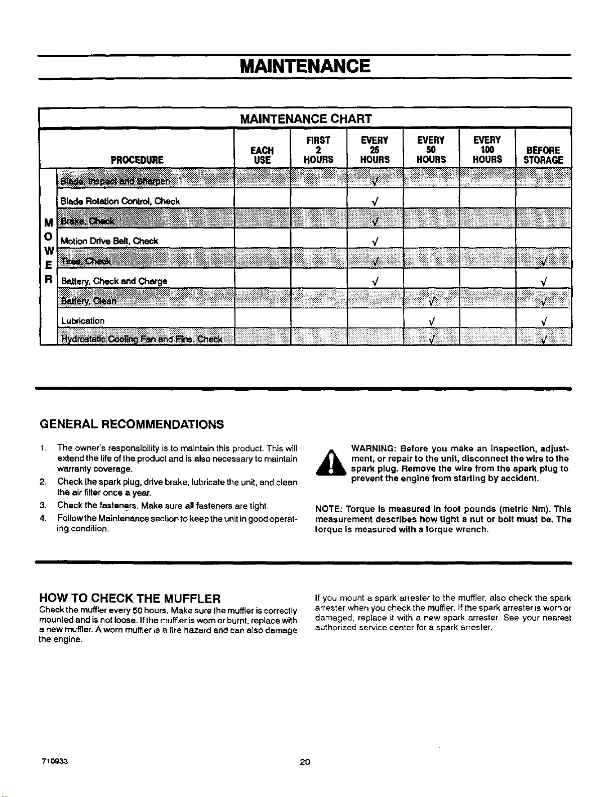
MAINTENANCE CHART .................................. 20
HOW TO CHECK THE MUFFLER .......................... 20
HOW TO REMOVE AND INSTALL THE BLADE .............. 21
HOW TO SHARPEN THE BLADE ....................... ... 21
HOW TO ADJUST THE BLADE ROTATION CONTROL ....... 22
HOW TO CHECK AND ADJUST THE DRNE BRAKE ......... 23
HOW TO CHECK AND ADJUST THE MOTION DRIVE BELT .. 23
HOW TO ADJUST THE SPEED CONTROL PEDAL ........... 24
MAINTENANCE FREE BAI"rERY .......................... 24
HOW TO CHARGE THE BAI-[ERY ......................... 24
WHERE TO LUBRICATE .................................. 25
HOW TO CHECK THE FUEL FILTER ....................... 25
CHECK THE TIRES ...................................... 25
HOW TO REMOVE THE MOWER HOUSING ................ 26
HOW TO INSTALL THE MOWER HOUSING ................. 26
HOW TO ADJUST THE GAUGE WHEELS .................. 27
HOW TO LEVEL THE MOWER HOUSING ................... 28
HOW TO REPLACE THE MOTION DRIVE BELT ............. 29
HOW TO REPLACE THE MOWER DRIVE BELTS ............ 3O
HOW TO REPLACE THE FUSE ............................ 31
HOW TO REPLACE THE LIGHT BULB ..................... 31
HOW TO CLEAN THE MOWER HOUSING .................. 31
STORAGE (OVER 30 DAYS) .............................. 31
TROUBLE SHOOTING CHART ........................ 32
SLOPE GUIDE ....................................... 33
REPAIR PARTS ...................................... 34
LAWN TRACTOR ACCESSORIES ...................... 58
YARDKING PERFORMANCE Two Year Limited Warranty
Yardking Performance warrants to the original purchaser that this unit shall be free from defects in material and workmanship
under normal use and service for a period ofTwo (2) Years from the date of purchase; however, this warranty does not cover
engines, accessories (such as snow blowers, snow blades, grass baggers and plows), transmissions, batteries and Normal
Wear Parts (except as noted below) or transaxles as the companies that manufacture these items furnishtheir own warranties
and provideservice through their authorized field service facilities. For additional information,see the warranties covering these
padiculerparts. Ifyouare uncertain whether your unitcontainsor isequipped withone ormore ofthese pads, consultyour dealer
priorto purchase. Subject tothe terms and conditions noted inthis LimitedWarranty, we shall, at our option, repair or replace
at no costto the original purchaser any part covered by this Umited Warranty during the applicable warranty period.
In the event the battery proves defective within ninety (90) days from the date of purchase, we will replace it withoutcharge. If
the battery proves defective after (90) days butwithin one hundred twenty (120) days from the date of purchase, we willreplace
itfor a charge of one half (1/2) ofthe retail price of the battery in effect at the time of return.
Normal Wear Parts are defined as belts, blades, blade adapters, pneumatic tires, headlights and seat covers. These parts are
warranted to be free from defects in material and workmanship as delivered with the product. Any claim for repair orreplacement
of Normal Wear Parts must be made withinthirty (30) days of the date of purchase. No claims involvingdamage caused from
material use, abuse or misuse will be honored.
This Yardking Performance Two (2) Year Limited Warranty isyour exclusive remedy; however, thiswarranty is void or does
not apply to any unit that has been tampered with, altered, misused, abused or used for rental or other commercial and/or
professional (non-homeowner) uses. Your warranty does not cover minor mechanical adjustments which are notdue to any
defect in material or workmanship. For assistance in making such adjustments, consult your InstructionBook.
Tomake a claim under thisYardking Performance Two (2) Year Limited Warranty, return the unit (orif authorized in advance,
the defective part) alongwith your proof ofpurchase toan Authorized Service Center near you. To locate the nearest Authorized
Service Center, callthe Central Parts Distributor foryour area shown inthe list providedwith your unitorcheck the Yellow Page
listings in your local telephone directory. If you return the entire unit, we will repair the unit. If we authorize the return of the
defective partonly,we willeither replace or repair the part. In thecase ofa defect in atransmission ordifferential(asdistinguished
from a transaxle), the entire transmission or differential must be returned since they do not include user serviceable pads.
ThisYardklng Performance Two (2) Year Limited Warranty givesyou specific legal rights, and you may alsohave other rights
which vary from state to state. This Limited Warranty Is given In lieu of all other expressed and implied warranties
Including the Implied warranty of merchantability and warranty of fitness for a particular purpose. If you need additional
information on this written warranty or assistance in obtaining service, write or call: Yardking Performance, Outdoor Power
Equipment, Customer Service Department, P.O. Box 268, Brentwood, Tennessee 37027. (1-800-289-8995)
710933 2
OWNER'S INFORMATION
Thisinstructionbook isforseveral differentmodels.The instructions
are written fora person withsome mechanical ability,Uke most ser-
vicebooks, notallthe steps are described. Steps onhowto loosenor
tightenfasteners are steps anyone canfollowwithsome mechanical
ability.Read and follow these instructionsbefore you usethe unit.
Knowyour product: Ifyou understandthe unitand howtheunitoper-
ates, youwill get thebestperformance. Asyou readthismanual, com-
pare the illustrations tothe unit. Learn the location and the function of
thecontrols.To help prevent aneccident, followthe operating instruc-
tions end thesafety rules. Keep this manual for future reference.
IMPORTANT: Many units are not assembled and are sold in car-
tons. It is the responsibility of the owner to make sure the assembly
instructions in this manual ere exactly followed. Other units are pur-
chased in an assembled condition,On assembled units, itisthe re-
spensibility of the owner to make sure the unit is correctly
assembled, The owner must carefully check the unit according to
the instructionsin this manual before it is first used.
RESPONSIBILITY OF THE OWNER
Environmental Awareness
The responsibility of the owner Is to follow the instructions below.
1. Carefully read and follow the rules for safe operation.
2+ Follow ell the assembly instructions.
3. Inspect the unit.
4. Make sure that the operator of the unit knows how to correctly
use all standard and accessory equipment.
5, Operate the unit only with guards, shields, and other safety
items in place end working correctly.
6+ Correctly adjust the unit.
7. Service the unitonly with authorized or approved replacement
parts.
8. Complete aft maintenance on the unit.
• Do not fillthe engine's fuel tank completely full.
• Drain fuel for off-season storage.
• Use only unleaded gasoline.
• Service the air cleaner regularly.
• Change oil regularly. Use 30W oil insummer.
• Tune-up the engine regularly.
• Keep equipment in efficientoperating condition.
• Dispose ofused engine oil properly.
,&
SAFETY RULES
Safe Operation Practices for Riding Vehicles
As Recommended by American National Standards Institute
WARNING: This cutting machine is capable of amputating hands and feet and throwing objects. Failure to observe the
following safety Instructions could result in serious injury or death to the operator or bystanders.
GENERAL OPERATION:
1. Read, understancland followallinstructions inthe InstructionBook, on the machine, theengine and with anyattachments before starting.
2. Only allow responsible adults familiar with the instructions to operate the machine.
3. Clear the area of objects such as rocks, toys, wire, etc. which could be picked up and thrownby the blade.
4. Be sure the area is clear of other people before mowing. Stop the machine if anyone enters the area.
5. Never carry passengers.
6. Disengage power to the mower or any attachments before backing up. Do not mow in reverse unless absolutely necessary. Always
look down and behind before and while backing.
7. Be aware of the direction the mower discharges. Do not point discharge from the mower at anyone or at places where people may be.
Do not operate the mower without either the entire grass bagger or the mower guard in place.
8. Slow down before turning.
9. Never leave a machine unattended with the engine running. Always disengage the blade(s), set the parking brake, stop the engine and
remove the key before dismounting.
10. Disengage power toattachment(s) when transporting or notin use. Disengage the blade(s) when not mowing.
11. Stop the engine before removing the grass bagger or unclogging the chute.
12. Mow only in daylight or good artificial light.
13. Do not operate the machine while under the influence of alcohol or drugs or when very tired.
14. Watch for trafficwhen operating near or crossing roadways.
15. Use extra caution when loading or unloading the machine when using a trailer or truck for transporting.
16. Disengage all attachment clutches before attempting to start the engine
17. Always wear safety glasses or an eye shield when you operate the unit to protect your eyes from foreign objects that can be thrown
from the unit. Always wear eye protection when you make an adjustment or repair to the machine.
18. Use care when pulling loads or using heavy equipment.
e. Use only approved drewbar hitch points.
b. Limit loads to those you can safely control.
c, Do not turnsharply. Use care when backing.
d. Use counterweights or wheel weights when suggested in the Instruction Book.
710933 3
OWNER'S INFORMATION
19. Do not operate this machine if you are taking drugs or other medication which can cause drowsiness or affect your ability tooperate
this machine.
20. Do not use this machine ifyou are mentally or physically unable to operate this machine safely.
SLOPE OPERATION:
Slopes and rough terrain are major factors related to loss of control and tip over accidents which can result In severe injury or
death. ALL ==lopes require extra caution. If you cannot back up the slope or if you feel uneasy on the slope, do not mow it. See the
"Slope Guide" In the back of this book to cheek for safe operation.
DO
1. Mow up end down slopes, not across.
2. Remove obstacles such as rocks, limbs, etc...
3. Watch for holes, ruts or bumps. Uneven terrain could ovedurn the machine. =Tallgrass can hide obstacles."
4, Use slow speed on slopes. Do not make sudden speed changes.
5. Follow the manufacturer's recommendations for wheel weights or counterweights to improve stabitity
6. Use extra care with grass baggers or other attachments, they can change the stabilityof the machine,
7. Keep all movement on the slopes slow and gradual. [30not make sudden changes in speed or direction.
8. Avoid starting or stopping on a slope, If tires lose traction,disengage the blades and proceed slowly straight down the slope.
DO NOT
1. Do not turn on slopes unless absolutely necessary, then onlyturn slowly and gradually downhill, if possible.
2. Do not mow near drop-offs, ditches or embankments. A wheel over the edge or anedge caving incould cause a sudden overturn and
an injuryor death.
3. Do not mow on wet grass. Reduced traction could cause sliding.
4. Do not try to stabilize the machine by putting your foot on the ground.
5. Do not use a grass bagger or other rear mounted accessories on steep slopes (greater than 10 degrees).
CHILDREN:
Tragic accidents can occur ifthe operator Is not alert to the presence of children. Children are often attracted to the machine and
the mowing activity. NEVER assume that children will remain where you last saw them.
1. Keep children out ofthe mowing area and inthe watchfulcare of an adult other than the operator.
2. Be alert and tLKnthe engine off if children enterthe area.
3. Before and when backing, look behind and down for small children.
4. Never carry children or any passengers. They may fall off and be seriously injuredor interfere with the safe operationof the machine.
5. Never allow children to operate the machine. Instructchildren in the dangers of the machine.
6. Use extra care when approaching blind corners, shrubs, trees or other objects that may obscure vision.
SERVICE:
1, Use extra care when handling gasoline and other fuels. Fuels ere flammable and the vapors are explosive.
a. Use only an approved container.
b. Never remove the gas cap or add fuel with the engine running. AIlow the engine to cool for several minutes before refueling, Do
not smoke.
c. Never refuel Ihe machine indoors
d. Never store the machine with fuel in the tank or fuel container inside where there is an open flame, such as awater heater.
2. Never star or run the engine inside a closed area.
3. Keep all nuts and.bolts, especially the blade attachment nuts tight. Frequently check the blade(s) for wear or damage such as cracks
and nicks. A blade that is bent or damaged must be immediately replaced with an original equipment blade from an autheri;_ed service
dealer. For safety, replace the blade every two years. Keep the equipment in good condition.
4. Never tamper with the safety devices. Check their proper operation regularly.
5. To reduce fire hazards keep the machine free of grass, leaves or other debris build-up, Clean up oil or fuel spills. Mow the machine
to cool before storing.
6, Stop and inspect the equipment if you strike an object. Repair, if necessary, before restarting.
7. Never make adjustments or repairs with the engine running. The carburetor can be adjusted with the engine running. Do not change
the engine governor settings or over-speed the engine.
8, Grass bagger components are subiect to wear, damage and deterioration, which could expose moving parts or allow objects to be
thrown. For storage, always make sure the grass bag is empty. Frequently check components and replace with manufacturer's recom-
mended pads when necessary.
9. Mower blade(s) ere sharp and can cut. Wrap the blade(s) or wear gloves and use extra caution when servicing them or the blade housing
area.
10. Check the brake operation frequently. Adjust and service as required.
11. Wait for all movement tostop before servicing any par ofthe unit.
,_ Look for this symbol to indicate Important safety
precautions, This symbol indicates: "Attention!
Become Alert! Your Safety Is At Risk."
710933
4
Each person that operates power
equipment must learn to use correct and
safe mowing procedures. To help you
learn, carefully read the following
pages. Most of the time the operator was
notcorrectly shown or did not read the
instructionson the unitor in the instruction
Book before using the'unit. Also, some
operators do not have enough experience.
The result isunsafe use, endangering the
operator, bystanders and the equipmenL
Another result can be a poor appearance
of the area mewed.
Read this book. Read the instructionson
the unit. Operate the mower according to
the Safe Mowing Guide. Followall safety
rules, cautions orwarnings in this book
and on the unit. Make sure anyone that
uses the unit reads the instructionsand is
told how to safely operate the mower.
The mower will give you good service and
durability,if operated in normal conditions.
Ifthe mower is not correctlyserviced or is
used where the terrain is rough or
unsuitable, product performance and
safety will be decreased.
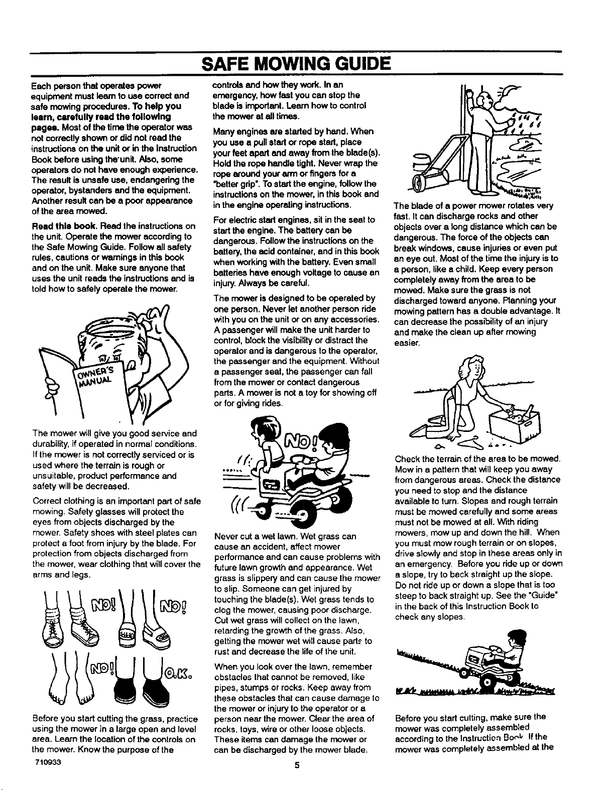
Correct clothing is an important part of safe
mowing. Safety glasses will protect the
eyes from objects discharged by the
mower. Safety shoes with steel plates can
protect a foot from iniuryby the blade. For
protection from objects discharged from
the mower, wear clothing that willcover the
arms and legs.
Before you start cuttingthe grass, practice
using the mower in a large open and level
area. Learn the location of the controls on
the mower. Know the purpose ofthe
71C_33
SAFE MOWING GUIDE
controlsand how they work. In an
emergency, how fast you can stop the
blade is important. Learn how to control
the mower at all times.
Many engines are started by hand. When
you use a pullstart or rope start, place
your feet apart and away from the blade(s).
Hold the rope handle tight.Never wrap the
rope around your arm or fingersfor a
"petter grip'. Tostart the engine, follow the
instructionson the mower, inthis book and
in the engine operating instructions.
For electric start engines, sitin the seat to
start the engine. The battery can be
dangerous. Followthe instructionson the
battery, the acid container, and in this book
when working withthe battery. Even smell
batteries have enough voltage to cause an
injury.Always be careful.
The mower is designed to be operated by
one person. Never let another person ride
with you on the unit or on any accessories.
A passenger will make the unitharder to
control, blockthe visibilityor distractthe
operatorand is dangerous tothe operator,
the passenger and the equipment. Without
a passenger seat, the passenger can fall
from the mower or contact dangerous
pads. A mower is not a toy for showing off
or for giving rides.
Never cut a wet lawn. Wet grass can
cause an accident, affect mower
performance and can cause problemswith
future lawn growthand appearance. Wet
grass isslippery and can cause the mower
to slip. Someone can get injuredby
touching the blade(s), Wet grass tends to
clog the mower, causing poor discharge.
Cut wet grass will collect on the lawn,
retarding the growth ofthe grass. Also,
gettingthe mower wet will cause pads to
rust and decrease the life of the unit.
When you look over the lawn, remember
obstacles that cannot be removed, like
pipes, stumps or rocks. Keep away from
these obstacles that can cause damage to
the mower or injuryto the operator or a
person near the mower. Clear the area of
rocks, toys,wire or other loose objects.
These items can damage the mower or
can bedischarged by the mower blade.
5
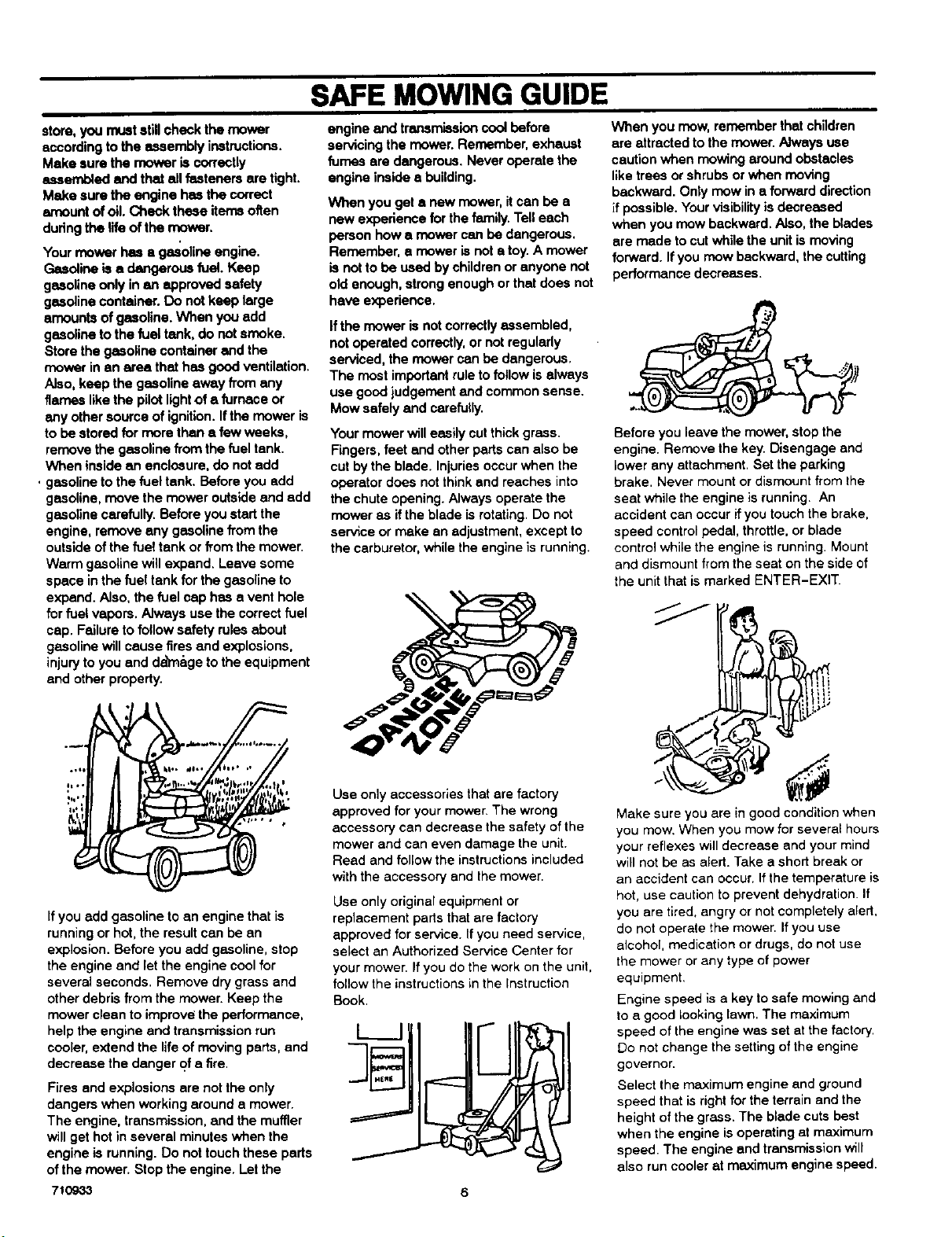
The blade of a power mower rotates very
fast. Itcan discharge rocks and other
objects over a long distance which can be
dangerous. The force of the objects can
break windows, cause injuriesor even put
an eye out. Most of the time the injury isto
a person, like a child. Keep every person
completely away from the area to be
mowed. Make sure the grass isnot
discharged toward anyone. Planning your
mowing pattern has a double advantage, it
can decrease the possibilityof an injury
and make the clean up after mowing
easier.
°
Check the terrain of the area to be mowed.
Mow in a pattern that will keep you away
from dangerous ames. Check the distance
you need to stop and the distance
available to turn. Slopes and roughterrain
must be mowed cerefully and some areas
must not be mowed at all. With riding
mowers, mow up and down the hill. When
you must mow roughterrain or on slopes,
drive slowly and stop in these areas only in
an emergency, Before you ride up or down
a slope, try to back straight up the slope.
Do notride up or down a slope that istoo
steep to back straight up. See the "Guide"
in the back of this InstructionBook to
check any slopes.
Before you start cutting, make sure the
mower was completely assembled
according to the Instruction Bo_L" !fthe
mower was completely assembled at the
store,youmuststillcheckthemower
according to the assembly instructions.
Make sure the mower is correctly
assembled and thai ell fasteners are tight•
Make sure the engine has the correct
amount of oil. Check these items often
during the life of the mower.
Your mower has • gasoline engine.
Gasoline is a dangerous fuel. Keep
gasoline only in an approved safety
gasoline container. Do not keep large
amounts ofgasoline. When you add
gasoline to the fuel tank, do not smoke.
Store the gasoline container and the
mower in an area that has good ventilation,
Also, keep the gasoline away from any
flames like the pilotlightof a furnace or
any other source of ignition. Ifthe mower is
to be stored for more than a few weeks,
remove the gasoline from the fuel tank.
When inside an enclosure, do not add
, gasoline tothe fuel tank. Before you add
gasoline, move the mower outside and add
gasoline carefully. Before you start the
engine, remove any gasoline from the
outside of the fuel tank or from the mower.
Warm gasoline willexpand. Leave some
space in the fuel tank for the gasoline to
expand. Also, the fuel cap has a vent hole
forfuel vapors. Always use the correct fuel
cap. Failure to follow safety rules about
gasoline will cause fires and explosions,
injuryto you and da_&ge tothe equipment
and other property.
If you add gasoline to an engine that is
running or hot, the result can be an
explosion. Before you add gasoline, stop
the engine and let the engine cool for
several seconds. Remove dry grass end
other debris from the mower. Keep the
mower clean to improve the performance,
help the engine end transmission run
cooler, extend the life of moving parts, and
decrease the danger of a fire.
Fires and explosions are not the only
dangers when working around a mower.
The engine, transmission, and the muffler
will get hot in several minutes when the
engine is running. Do nottouch these parts
of the mower. Stop the engine. Let the
71O933
SAFE MOWING GUIDE
engine and transmission cool before
servicing the mower. Remember, exhaust
fumes ere dangerous. Never operate the
engine inside e building.
When you get a new mower, it can be a
new experience for the family. Tell each
person how a mower can be dangerous.
Remember, a mower is not atoy. A mower
is notto be used by children or anyone not
old enough, strong enough or that does not
have experience.
If the mower isnot correctly assembled,
not operated correctly,or notregularly
serviced, the mower can be dangerous,
The most importantrule to follow is always
use good judgement and common sense.
Mow safely and carefutly.
Your mower will easily cutthick grass.
Fingers, feet and other parts can also be
cut bythe blade. Injuriesoccur when the
operator does not think and reaches into
the chute opening. Always operate the
mower as ifthe blade is rotating. Do not
service or make an adjustment, except to
the carburetor, while the engine is running.
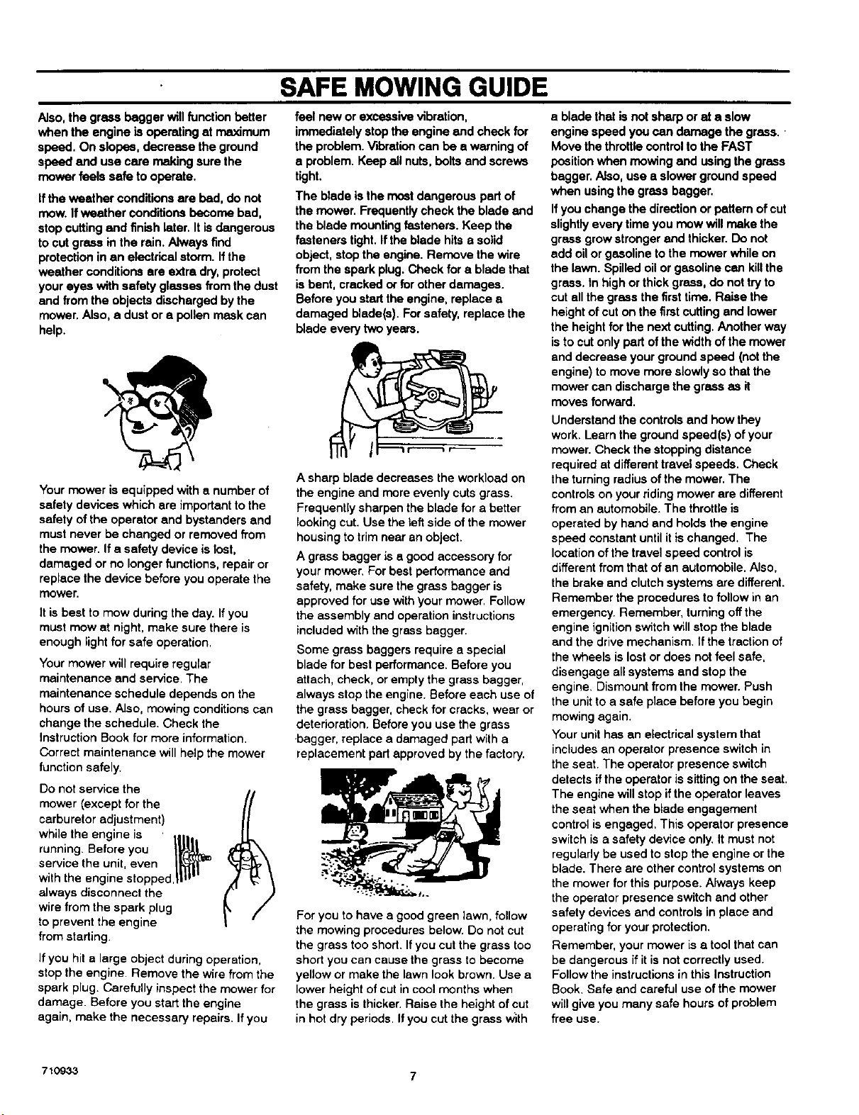
When you mow, remember that children
are attracted to the mower. Always use
caution when mowing around obstacles
like trees or shrubs or when moving
backward. Only mow in a forward direction
if possible. Your visibility is decreased
when you mow backward, Also, the blades
are made tocut while the unit ismoving
forward. Ifyou mow backward, the cutting
performance decreases.
Before you leave the mower, stop the
engine. Remove the key. Disengage and
lower any attachment, Set the parking
brake. Never mount or dismount from the
seat while the engine is running. An
accident can occur if you touch the brake,
speed control pedal, throttle, or blade
control while the engine is running. Mount
and dismount from the seat on the side of
the unitthat ismarked ENTER-EXIT.
Use only accessories thatare factory
approved for your mower. The wrong
accessory can decrease the safety of the
mower and can even damage the unit.
Read and followthe instructionsincluded
with the accessory end the mower.
Use only original equipment or
replacement parts that are factory
approved for service. If you need service,
select an Authorized Service Center for
your mower. Ifyou do the work on the unit,
follow the instructionsinthe Instruction
Book.
I I
=li
Make sure you are in good condition when
you mow. When you mow for several hours
your reflexes will decrease and your mind
will not be as alert. Take a short break or
an accident can occur. If the temperature is
hot, use caution to prevent dehydration. If
you ere tired, angry or not completely alert.
do not operate the mower. If you use
alcohol, medication or drugs, do not use
the mower or any type of power
equipment,
Engine speed is a key to safe mowing and
to a good looking lawn. The maximum
speed of the engine was set at the factory.
Do not change the setting of the engine
governor.
Select the maximum engine end ground
speed that is right for the terrain and the
height of the grass. The blade cuts best
when the engine is operating at maximum
speed. The engine and transmission will
also run cooler at maximum engine speed.
6
SAFE MOWING GUIDE
Also, the grass begger will functionbetter
when the engine isoperating at mmdmum
speed. On slopes, decrease the ground
speed and use care making sure the
mower feels safe to operate.
Ifthe weather conditions are bed, do not
mow. Ifweather conditionsbecome bad,
stop cuttingend finish later. It isdangerous
tocut grass in the rain. Always find
protection in an aiectdcat storm. Ifthe
weather conditions are extra,dry,protect
your eyes with safety glasses from the dust
and from the objects discharged by the
mower. Also, a dust or a pollen mask can
help.
Your mower isequipped with a number of
safety devices which are important tothe
safety of the operator and bystanders and
must never be changed or removed from
the mower. If a safety device is lost,
damaged or no longer functions, repair or
replace the device before you operate the
mower.
it is best to mow during the day. Ifyou
must mow at night, make sure there is
enough light forsafe operation.
Your mower will require regular
maintenance and service. The
maintenance schedule depends on the
hours of use. Also, mowing conditions can
change the schedule. Check the
instruction Book for more information.
Correct maintenance will helpthe mower
function safely.
Do not service the
mower (except for the
carburetor adjustment)
while the engine is ' ,...
running. Before you _ !
service the unit, even I_1_j'_-
with the engine stopped,||t _
always disconnect the
wire from the spark plug
to prevent the engine
from starting.
Ifyou hit a large object during operation,
stopthe engine. Remove the wire from the
spark plug. Carefully inspect the mower for
damage. Before you start the engine
again, make the necessary repairs. Ifyou
feel new or excessive vibration,
immediately stopthe engine and check for
the problem. Vibrationcan be a warning of
a problem. Keep all nuts, bolts and screws
tight.
The blade is the most dangerous pad of
the mower. Frequently check the blade and
the blade mounting fasteners. Keep the
fasteners tight. Ifthe blade hits a solid
object, stop the engine. Remove the wire
fromthe spark plug. Check for a blade that
is bent, cracked or for other damages.
Before you start the engine, replace a
damaged blade(s). Forsafety, replace the
blade every two years.
A sharp blade decreases the workload on
the engine and more evenly cuts grass.
Frequently sharpen the blade for a better
lookingcut. Use the left side of the mower
housing totrim near an object.
A grass bagger is a good accessory for
your mower, For best performance and
safety, make sure the grass bagger is
approved for use with your mower. Follow
the assembly and operationinstructions
included with the grass bagger.
Some grass baggers require a special
blade for best performance. Before you
attach, check, or empty the grass bagger,
always stop the engine. Before each use of
the grass bagger, checkfor cracks, wear or
deterioration. Before you use the grass
bagger, replace a damaged part with a
replacement part approved by the factory.
For you to have a good green lawn, follow
the mowing procedures below. Do notcut
the grass too shod. Ifyou cut the grass too
short you can cause the grassto become
yellow or make the lawn lookbrown. Use a
lower height ofcut in cool months when
the grass isthicker. Raise the height ofcut
in hot dry periods. Ifyou cut the grass With
a blade thatis not sharp or at a slow
engine speed you can damage the grass.
Move the throttlecontrolto the FAST
positionwhen mowing and usingthe grass
bagger. Also, use a slowerground speed
when using the grass bagger.
Ifyou change the direction or pattem of cut
slightlyevery time you mow will make the
grass grow strongerand thicker. Do not
add oilor gasoline to the mower while on
the lawn. Spilled oil or gasoline can killthe
grass. In highor thick grass, do nottry to
cut all the grass the first time. Raise the
height of cut on the first cutting and lower
the heightfor the next cutting. Another way
isto cut only part ofthe width of the mower
and decrease your ground speed (not the
engine) to move more slowlyso that the
mower can discharge the grass as it
moves forward.
Understand the controlsand how they
work. Learn the groundspeed(s) of your
mower. Check the stopping distance
required at differenttravel speeds. Check
the turning radius ofthe mower. The
controlson your riding mower are different
from an automobile. The throttleis
operated by hand and holds the engine
speed constant until itis changed. The
location ofthe travel speed control is
differentfrom that of an automobile. Also,
the brake and clutchsystems are different.
Remember the procedures tofollow in an
emergency. Remember, turning offthe
engine ignition switch will stop the blade
and the drive mechanism. If the tractionof
the wheels islost or does not feel safe,
disengage allsystems and stop the
engine. Dismount fromthe mower. Push
the unitto a safe place before you begin
mowing again.
Your unithas an electrical system that
includesan operator presence switch in
the seat. The operator presence switch
detects ifthe operator is sittingon the seat.
The engine will stop ifthe operator leaves
the seat when the blade engagement
control is engaged, This operator presence
switch is a safety device only.It must not
regularlybe used to stop the engine or the
blade. There are other control systems on
the mower for this purpose. Always keep
the operator presence switch and other
safety devices and controlsin place and
operating foryour protection.
Remember, your mower is a toolthat can
be dangerous ifit isnot correctly used.
Follow the instructionsin this Instruction
Book, Safe and careful use of the mower
willgive you many safe hours of problem
free use.
710933 7
STEPS TO FOLLOW
BEFORE MOWING
• Be sure to dress correctly.Wear hard shoes, notsandals or tennisshoes.
• Examine the blade. A blade that is bent, cracked, or damaged must he replaced with e factory replacement blade.
• Fillthe fuel tank outside. Clean offspilled fuel.
• Read end folk)w the Owner's Manual, the instructions with the engine, and the instructions with any attachments, Owner's Manual
instructionsare for your safety and the safety of others.
• Exhaust fumes ere dangerous. Start the engine outside,
• Make sure all safety devices ere in place end workingcorrectly.
• Operation ofthe mower is onlyfor e person that has experience.
• Wet grass can be dangerous, Let the grass dry.
• instructchildren and others to keep away from the work area.
• Never cutthe grass without good light,
• Pick up loose objects. Remove them from the mowing area,
WHILE MOWING
• Watch for fixed objects and avoid them. They can damage the mower or cause injury.
• A hot engine, muffler,and transmission willcause e burn. Do not touch.
• Inclines and slopes must be carefully mowed. See the "Guide" in the back of this book to check a slope,
• Lack of daylight or good adificial light is cause to stop mowing.
• Examinethem_wer'theb__de_andotherpadsf_rdamageafterhittingaf_reign_bject_riftheunitvibratesexcessively`
• Do not make adjustments or repairs without stoppingthe engine. Disconnect the spark plug wire.
• On or near roads, watch out for traffic. Direct discharge away from roads.
• When mewing, avoid areas where tractionis unsure. Look back before changing direction of travel.
• In heavy grass, raise the cutting height. Cut slower. Stop the engine to remove clogged grass from the mower,
• Never remove any safety related pads.
• Do not pour gasoline intoa engine that is hotor running.
AFTER MOWING
• Always letthe mower cool before storing in an enclosed area,
• Foreign material on the mower is dangerous. Clean off grass, reaves, grease and oil before storing.
• Tighten all loose nuts, belts and screws before you use the unit.
• Empty and clean any grass catcher or other accessory.
• Remove the key or disconnect the spark plug wire to prevent unauthorized use.
• Make sure the mower is not kept near a source of ignition. Gas fumes can cause an explosion.
• Only original pads or factory approved substitutescan be used to service the mower.
• When storing the mower for an extended period, remove the fuel from the fuel tank,
• Instruct children to leave the mower alone. It is not a toy,
• Never keep gasoline near a source of ignition. Always use an approved container, Keep gasoline away from children.
• Lubricate according to the Instruction Book. See "Lubrication'.
IMPORTANT--Road the Instruction Book. Keep this book for future use and reference.
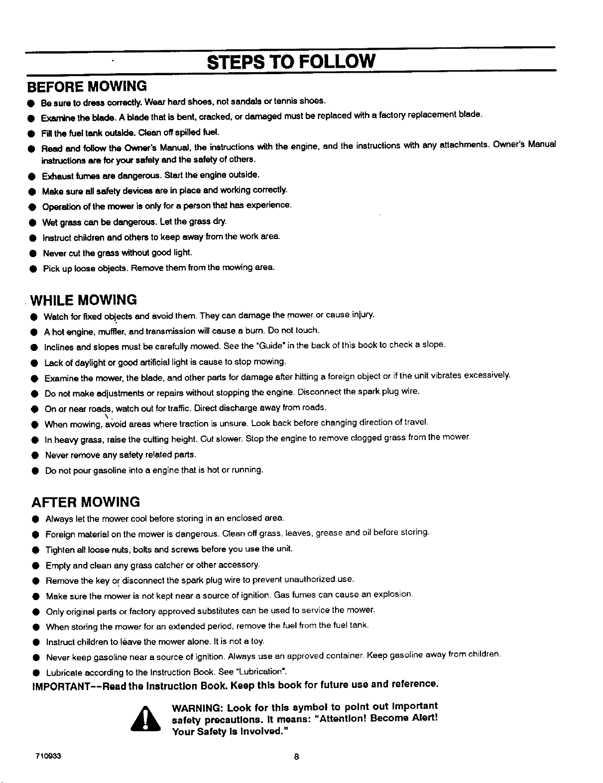
WARNING: Look for this symbol to point out Important
safety precautions. It means: "Attention! Become Alert!
Your Safety Is Involved,"
710933 8
ASSEMBLY
ASSEMBLY
This instructionbook isfor several models. Some partsor ecossso-
rias are not included on all models. Read and follow the assembly
and adjustment instructionsforyour mower. Allfasteners are in the
parts bag. Do not discard any parts or material until the unit is
assembled.
_IL WARNING: Before doing any assembly or mainte-
nance to the mower, remove the wire from the spark
plug.
NOTE: in this Instruction book, left and dght describe the loca-
tion of a part with the operator on the seat.
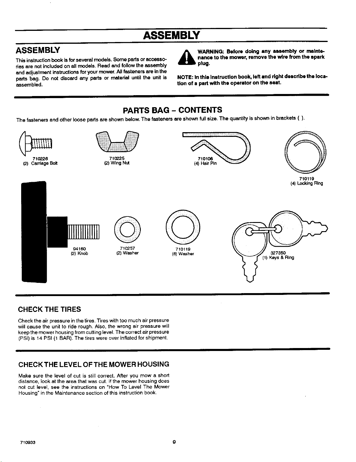
PARTS BAG - CONTENTS
The fasteners and other loose parts are shown below.The fasteners are shown full size. The quantity isshown in brackets ().
710226 71_P-25
(2) CarriageBolt (2)WingNut
94160
(2) Knob
71(_57
(2) Washer
710119
(8) W_her
_7350
(1) Keys & Ring
O
710119
(4) LockingRing
CHECK THE TIRES
Check the air pressure in the tires.Tires with too much air pressure
will cause the unit to ride rough. Also, the wrong air pressure will
keep the mower housing from cuttinglevel, The correct air pressure
(PSI) is 14 PSI (1 BAR). The tires were over inflated for shipment.
CHECKTHE LEVEL OFTHE MOWER HOUSING
Make sure the level of cut is stillcorrect, After you mow a short
distance, look at the area that was cut. Ifthe mower housing does
not cut level, see the instructions on "How To Level The Mower
Housing" in the Maintenance section of this instruction book,
710933 9
ASSEMBLY
3.
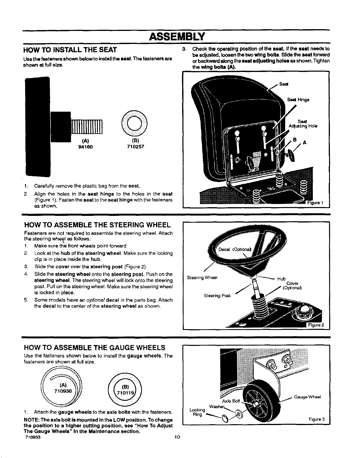
HOW TO INSTALL THE SEAT
Use the fasteners shown belowto installthe seat. The fasteners ere
shown at full size,
Check the operating positionof the seat. If the seat needs to
be adjusted, loosenthe two wing bolts. Slide the seat forward
orbackward along theseat adjusting holes as shown. Tighten
the wing bolt_ (A).
1.
2.
(A) (B)
94160 710257
Carefully remove the plastic bag from the seat.
Align the holes in the seat hinge to the holes in the seat
(Figure 1). Fasten the seat tothe seat hinge withthe fasteners
as shown.
Seat
Seal Hinge
A
HOW TO ASSEMBLE THE STEERING WHEEL
Fasteners are not required to assemble the steering wheel. Attach
the steering wheel as follows:
1. Make sure the front wheels point forward.
2. Look at the hub of the steering wheel. Make sure the locking
clip is in piece inside the hub.
3. Slide the cover over the steering post (Figure 2).
4. Slide the steering wheel onto the steering poet. Push on the
steorlng wheel. The steering wheel will lock onto the steering
post. Pull on the steering wheel. Make sure the steering wheel
is locked in place.
5. Some models have an optional decal in the parts bag. Attach
the decal to the center of the steering wheel as shown.
Steering Wheel
Steering Post
Hub
Cover
(Optional)
HOW TO ASSEMBLE THE GAUGE WHEELS
Use the fasteners shown below to install the gauge wheels, The
fasteners are shown at full size.
1. Attach the gauge wheels to the axle bolts with the fasteners.
NOTE: The axle bolt Ismounted In the LOW position. To change
the position to a higher cutting position, see "How To Adjust
The Gauge Wheels" in the Maintenance section.
710933
Locking
Ring
10
Axle Bolt
.=Wheel
Figure 3
ASSEMBLY
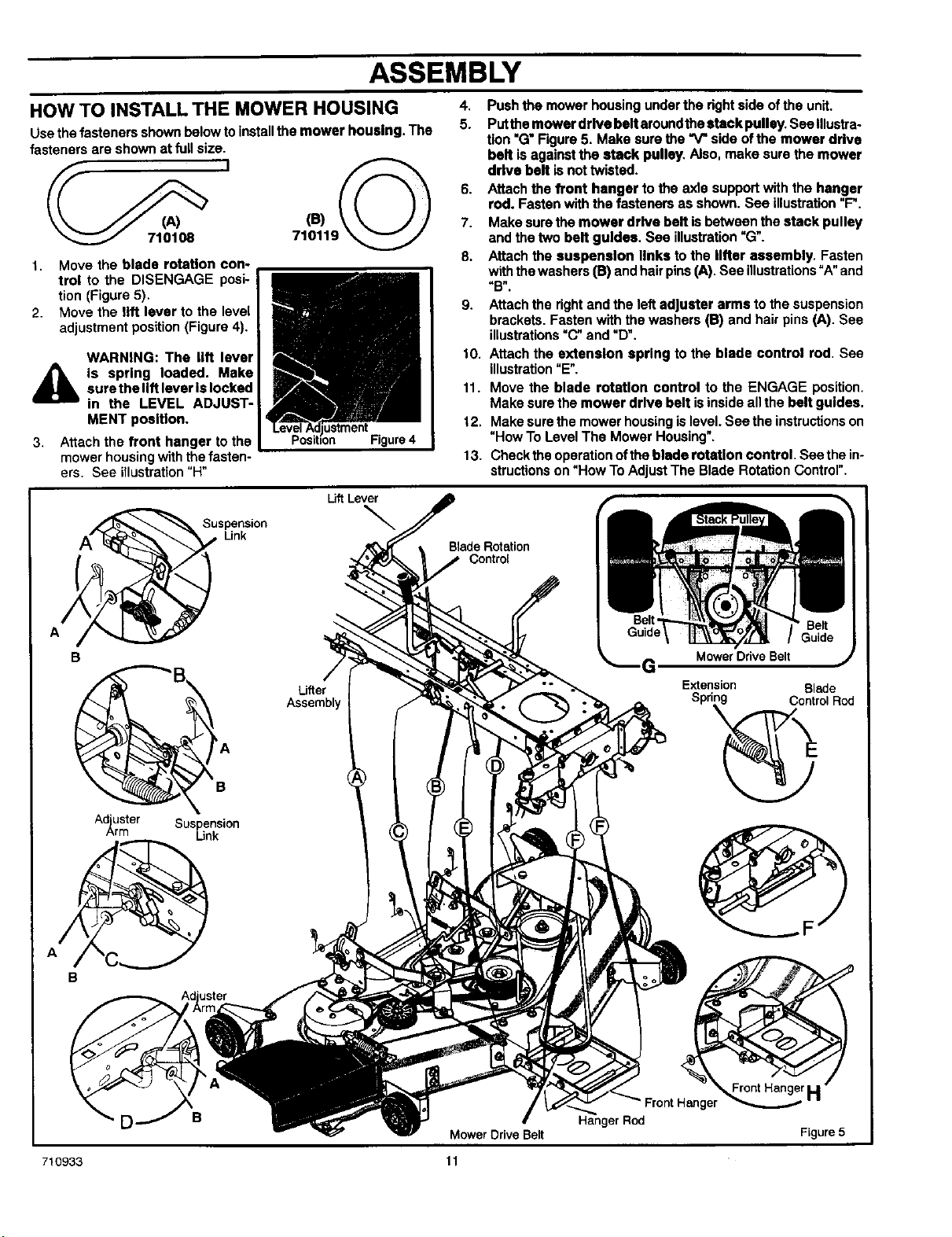
HOW TO INSTALL THE MOWER HOUSING
Use the fasteners shown below toInstall the mower housing. The
fasteners are shown at full size.
I
1. Move the blade rotation con-
trol to the DISENGAGE posi-
tion (Figure 5).
2. Move the lift lever to the level
adjustment position (Figure 4).
WARNING: The lift lever
iS spring loaded. Make
sure the lift lever Is locked
in the LEVEL ADJUST-
MENT position.
3. Attach the front hanger to the
mower housing with the fasten-
ers. See illustration"H"
Figure 4
4. Push the mower housing under the dght side of the unit.
5. Putthe mower drive belt aroundthe stack pulley. See Illustra-
tion "G" Figure 5. Make sure the "V" side ofthe mower drive
belt is against the ldack pulley. Also, make sure the mower
drive belt is not twisted.
6. Attach the front hanger to the axle support with the hanger
rod. Fasten with the fasteners as shown. See illustration"F".
7. Make sure the mower drive beR is between the stack pulley
and the two belt guides. Sea illustration"G".
8. Attach the suspension links to the lifter assembly. Fasten
withthe washers (B) and hair pins (A). See illustrations"A"and
"B".
9. Attach the rightend the left adjuster arms to the suspension
brackets. Fasten with the washers (13)and hair pins (A). See
illustrations"C" and "D".
10. Attach the extension spring to the blade control rod. See
illustration"E".
11. Move the blade rotstlon control to the ENGAGE position.
Make sure the mower drive belt isinside allthe belt guides.
12. Make surethe mower housingis level. See the instructionson
"How To Level The Mower Housing".
13. Check the operation of the blade rotstlon control. See the in-
structions on "How To Adjust The Blade Rotation Control".
B
Ad'uster
_rm
Suspension
Link
P'A
B
Suspension
Link
Lift Lever
\
Lifter
Assernbl
Blade Rotation
Control
Mower Drive Belt
Extension Blade
Spd_rol Rod
D B
uster
Hanger Rod
Front_
Figure 5
Mower Drive Belt
710933 11
ASSEMBLY
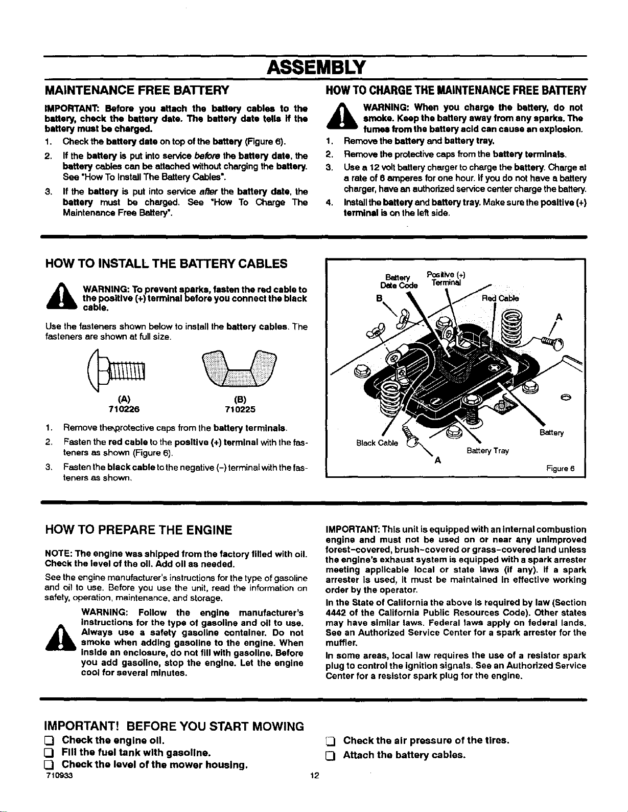
MAINTENANCE FREE BATTERY HOWTO CHARGETHE MAINTENANCEFREEBATTERY
IMPORTANT:. Before you attach the battery cables to the
battery, check the battery date. The battery date tells if the
battery must be charged.
1. Check the battery date on top of the battery (Figure 6).
2. If the battery is put into service before the battery date. the
battery cables can be attached without charging the battery.
See "How To Install The Battery Cables*.
3. If the battery is put into service alter the battery date, the
battery must be charged. See "How To Charge The
Maintenance Free Battery'.
A
1.
2.
3.
4,
WARNING: When you charge the battery, do not
smoke. Keep the battery away from any sparks. The
fumes from the battery acid can cause an explosion.
Remove the battery and battery tray.
Remove the protective caps from the battery terminals.
Use a 12 volt battery charger to charge the battery. Charge at
s rate of 6 amperes for one hour. if you do not have a battery
charger, have an authorized service center charge the battery.
Installthe battery and battery tray. Make sure the pesltlve (+)
terminal is on the leftside.
HOW TO INSTALL THE BATTERY CABLES
_k WARNING: To prevent sparks, fasten the red cable to
the positive (+) terminal before you connect the black
cable.
Use the fasteners shown below to install the battery cables. The
fasteners are shown st fullsize.
(A) (B)
710226 710225
1. Remove the_rotective caps from the battery terminals.
2. Fasten the red cable to the positive (+) terminal with the fas-
teners as shown (Figure 6).
3. Fasten the black cable tothe negative (-) terminalwith the fas-
teners as shown,
I positive(+) I
_Ek_te___ Terminal
e A
/
HOW TO PREPARE THE ENGINE
NOTE: The engine was shipped from the factory filled with oil.
Cheek the level of the oil. Add oil aa needed.
Bee the engine manufacturer's instructions for the type of gasoline
and oil to use. Before you use the unit, read the information on
safety, operation, maintenance, and storage,
WARNING: Follow the engine manufacturer's
instructions for the type of gasoline and oil to use.
Always use a safety gasoline container. Do not
smoke when addthg gasoline to the engine. When
inside an enclosure, do not fill with gasoline. Before
you add gasoline, stop the engine. Let the engine
cool for several minutes.
IMPORTANT: This unit is equipped with an internal combustion
engine and must not be used on or near any unimproved
forest-covered, brush-covered or grass-covered land unless
the engine's exhaust system is equipped with a spark arrester
meeting applicable local or state laws (if any). If a spark
arrester is used, it must be maintained in effective working
order by the operator.
In the State of California the above Is required by law (Section
4442 of the California Public Resources Code). Other states
may have similar laws. Federal laws apply on federal lands.
See an Authorized Service Center for a spark arrester for the
muffler,
In some areas, local law requires the use of a resistor spark
plug to control the ignition signals. See an Authorized Service
Center for a resistor spark plug for the engine.
IMPORTANT! BEFORE YOU START MOWING
[3 Check the engine oil.
[_ Fill the fuel tank with gasoline.
[_ Check the level of the mower housing.
710933
_1 Check the air pressure of the tires.
[3 Attach the battery cables.
12
OPERATION
ThrottleControl
Lever
Blade Rotation
Control
Brake Pedal
Speed
Control
P_ial
Figure 7
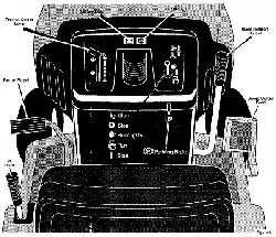
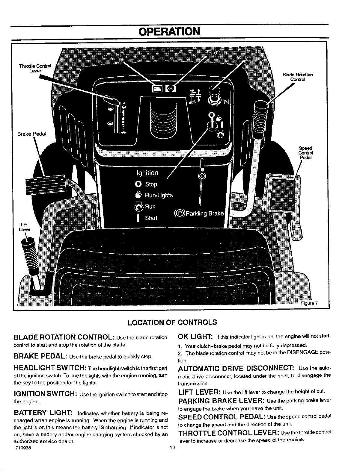
LOCATION OF CONTROLS
BLADE ROTATION CONTROL: Use the blade rotation
control to start and stop the rotationof the blade.
BRAKE PEDAL: Use the brake pedal toquickly stop.
HEADLIGHT SWITCH: The headlight switch isthefirst part
of the ignitionswitch. To use the lights with the engine running, turn
the key to the position forthe lights.
IGNITION SWITCH: usetheignitionswitchtostartandstop
the engine,
BATTERY LIGHT: Indicates whether battery is being re-
charged when engine is running. When the engine is running and
the light is on this means the battery IS charging. If indicator is not
on, have a battery and/or engine charging system checked by an
authorized service dealer.
710933
OK LIGHT: Ifthisindicatorlightison,theenginewillnotstart.
1. Your clutch-brake pedal may not be fully depressed.
2. The blade rotationcontrol may not be in the DISENGAGE posi-
tion.
AUTOMATIC DRIVE DISCONNECT: Usetheauto-
matic drive di,_connect,located under the seat, to disengage the
transmission.
LIFT LEVER: Use the liftleverto change the height of cut.
PARKING BRAKE LEVER: usetheparkingbrake lever
toengage the brake when you leave the unit.
SPEED CONTROL PEDAL: Usethe speedcontrolpedal
to change the speed and the direction of the unit.
THROTTLE CO NTROL LEVER: usethe throttle control
lever to increase or decrease the speed of the engine,
13
OPERATION
ATTACHMENTS HOWTO USETHE BLADEROTATIONCONTROL
This unitcan use many ditfemntattachments. See the attachment
page in this book. This unit can pull attachments like a lawn
sweeper, a lawn aerator, or a hopper spreader. This unitcan notuse
attachments that engage the ground like a plow,a disk harrow,or
a cultivator.
HOW TO USE THE THROTTLE CONTROL
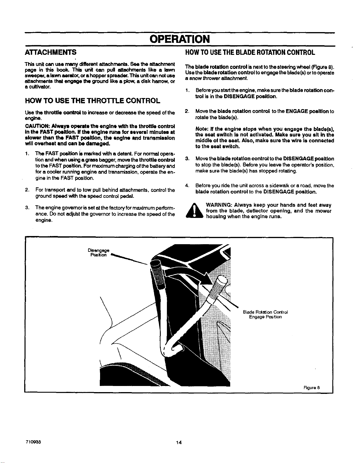
The blade rotation control is next totho steering wheel (Figure 8).
Use the blade rotation control toengage the blade(s) orto operate
• snow thrower attachment.
1. Before you start the engine, make surethe blade rotation con-
trol is in the DISENGAGE poattlon•
Use the throttle €_)ntrol to increase or decrease the speed of the
engine.
CAUTION: Always operate the engine with the throttle control
In the FAST posiflon. If the engine mrle for several minutes st
slower than the FAST position, the engine end transmission
will overheat end ran be damaged.
1. The FAST praition is marked with a detent. For normal opera-
tionand when using a grass bagger, move the throttle control
tothe FAST position. For maximum chargingof the batteryend
for a cooler running engine end transmission, operate the en-
gine inthe FAST position.
2.
3,
For transport end to tow pull behind attachments, control the
ground speed with the speed control pedal.
The engine governoris set at the factoryformaximum perform-
ance. Do not edjt._t the governor to increase the speed ofthe
engine.
2. Move the blade rotation control tothe ENGAGE position to
rotate the blade(s).
Nots: If the engine stops when you engage the blade(s),
the seat switch Is not activated. Make sure you sit In the
middle of the seat. Also, make sure the wire Is connected
to the seat switch.
3. Move the blade rotation control tothe DISENGAGE position
to stop the blade(s). Before you leave the operator's position,
make sure the blade(s) has stopped rotating,
4. Before you ride the unitacross asidewalk ora road, move the
blade rotation control to the DISENGAGE position.
_1 WARNING: Always keep your hands and feet away
from the blade, deflector opening, and the mower
housing when the engine runs.
Disengage
Position
B_adeR_=ionCo_rol
Engage Pc_s_ion
Figure 8
7109,33 14
OPERATION
HOW TO USE THE SPEED CONTROL PEDAL
The drive system uses a HydrostaticAutomatic Drive transmission.
The Hydrostatic transmission is very easy to operate. This type of
drive system does not require e shiRlever or a clutch pedal.
The speed end direction of travel is controlled by a single speed
control pedal operated withyour rightfoot. Donotusethe leftbrake
pedal in normal operation. Only use the left brake pedal to quickly
stop in an emergency.
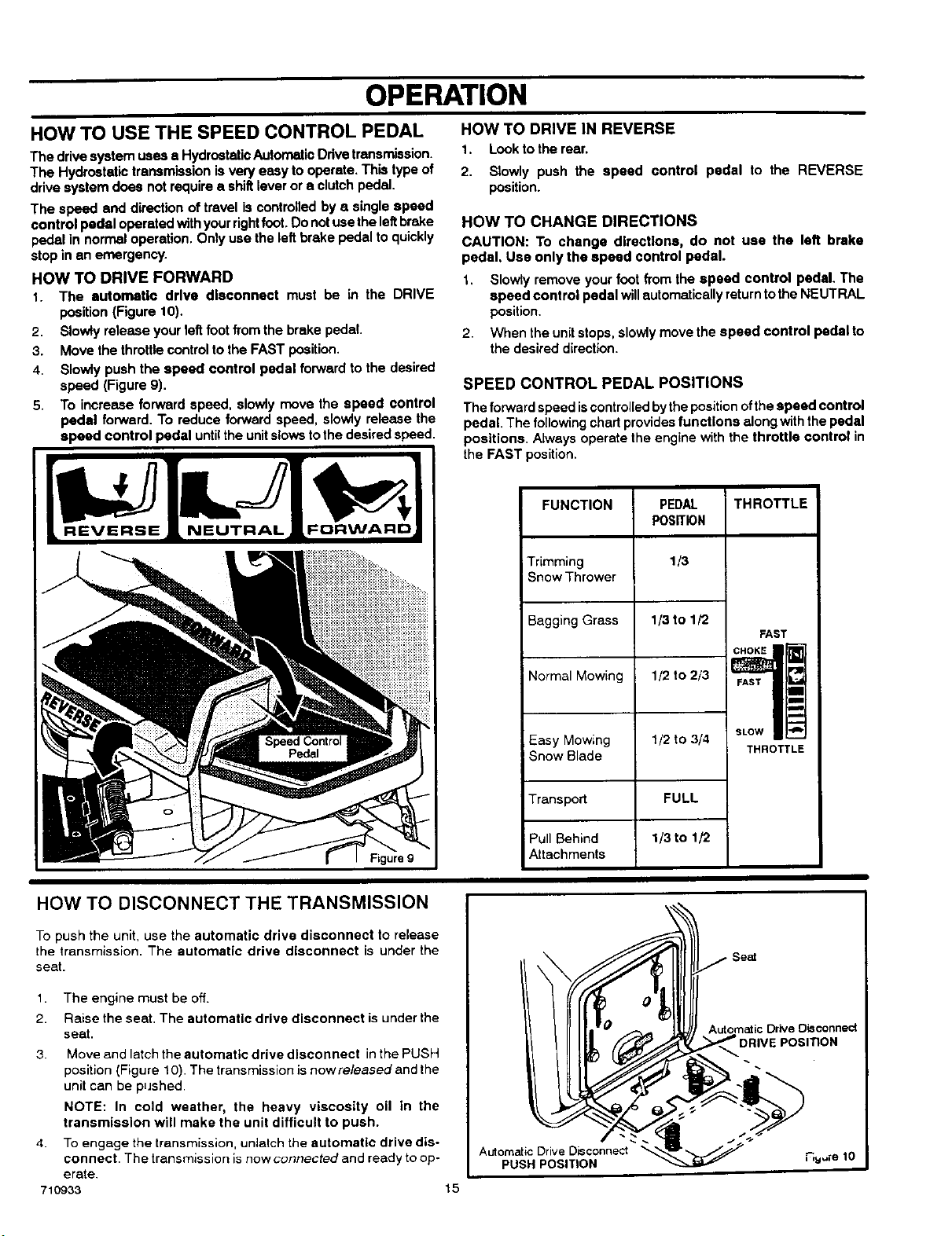
HOW TO DRIVE FORWARD
1. The automatic drive dlaconnest must be in the DRIVE
position (Figure 10).
2. Slowly release your left footfrom the brake pedal.
3. Move the throttlecontrol tothe FAST position.
4. Slowly push the speed control pedal forward to the desired
speed (Figure 9).
5+ To increase forward speed, slowly move the speed control
pedal forward. To reduce forward speed, slowly release the
speed control pedal untilthe unitslows tothe desired speed.
HOW TO DRIVE IN REVERSE
1. Look to the rear.
2. Slowly push the speed control pedal to the REVERSE
position.
HOW TO CHANGE DIRECTIONS
CAUTION: To change diracttons, do not use the left brake
pedal, Use only the speed control pedal.
1. Slowly remove your foot from the speed control pedal. The
speed control pedal willautomatically returnto the NEUTRAL
position.
2. When the unitstops, slowly move the speed control pedal to
the desired direction.
SPEED CONTROL PEDAL POSITIONS
The forward speed iscontrolledby the positionofthe speed control
pedal. The following chad providesfunctions along with the pedal
positions. Always operate the engine with the throttle control in
the FAST position.
FUNCTION THROTTLE
Trimming
Snow Thrower
Bagging Grass
Normal Mowing
Easy Mowing
Snow Blade
Transport
Pull Behind
Attachments
PEDAL
POSITION
1/3
1/3 to 1/2
1/2 to 2/3
1/2 to 3/4
FULL
1/3 to 1/2
FAST
CHOKE __
FAST
_l
m
m
m
u
SLOW
THROTTLE
m
HOW TO DISCONNECT THE TRANSMISSION
To push the unit, use the automatic drive disconnect to release
the transmission. The automatic drive disconnect is under the
seat.
1. The engine must be off.
2. Raise the seat. The automatic drive disconnect is under the
seat.
3. Move and latch the automatic drive disconnect in the PUSH
position {Figure 10). The transmission is nowreleasedand the
unit can be pushed
NOTE: In cold weather, the heavy viscosity oil in the
transmission will make the unit difficult to push.
4. To engage the transmission, unlatch the automatic drive dis-
connect. The transmission is now connected and ready to op-
erate.
710933
Automatic Drive Disconnect
PUSH POSITION
15
Automatic Drive Disconnect
POSITION
OPERATION
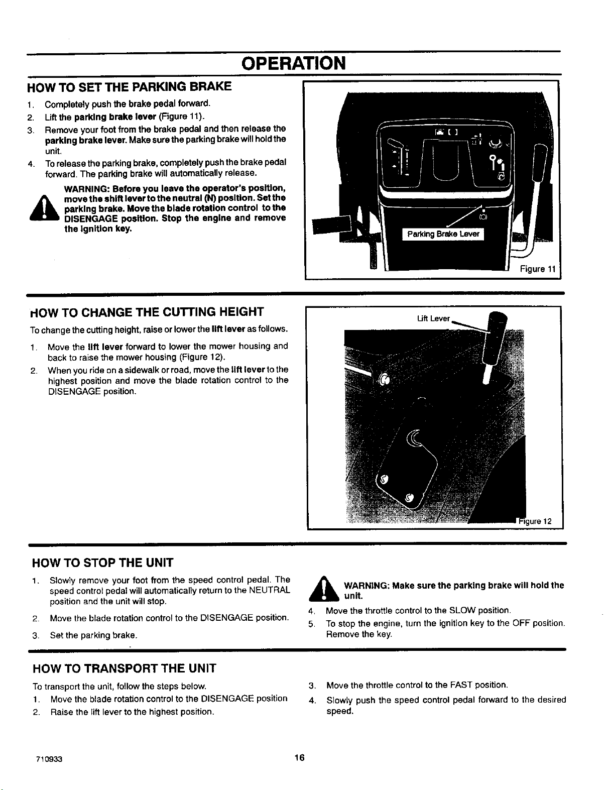
HOW TO SET THE PARKING BRAKE
1.
2.
3.
4.
A
Completely push the brake pedal forward.
Liftthe parking brake lever (Figure 11).
Remove your foot from the brake pedal and then release the
parking brake lever. Make sure the parking brake will holdthe
unit,
Torelease the parking brake, completely pushthe brake pedal
forward. The parking brake will automatically release.
WARNING: Before you leave the operator's position,
move the shift lever to the neutral (N) poslUon. Set the
parking brake. Move the blade rotation control tothe
DISENGAGE position. Stop the engine and remove
the Ignition key.
Figure 11
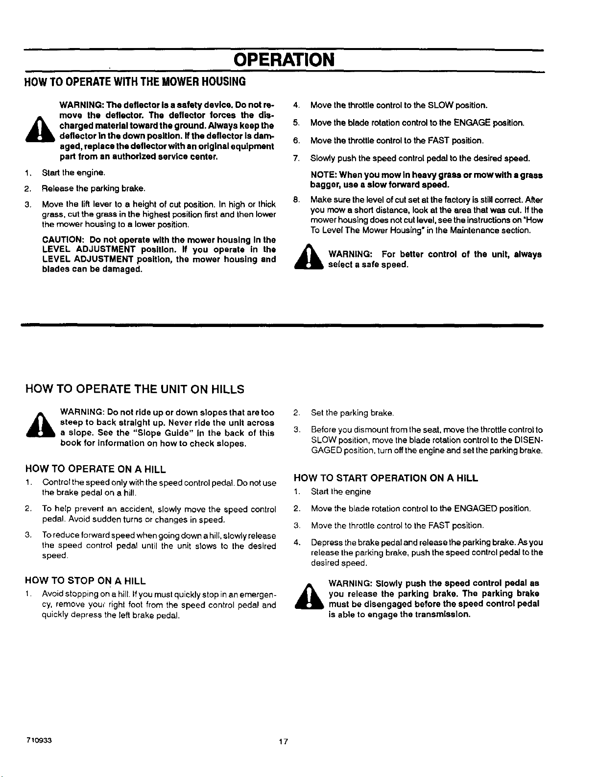
HOW TO CHANGE THE CUTTING HEIGHT
To change the cuttingheight, raise or lower the lift lever asfollows.
1. Move the lift lever forward to lower the mower housing and
back to raise the mower housing (Figure 12).
2. When you ride ona sidewalk or road, move the lift lever tothe
highest position and move the blade rotation control to the
DISENGAGE position.
Uff Lever
HOW TO STOP THE UNIT
1.
Slowly remove your foot from the speed control pedal. The
speed control pedal will automatically return tothe NEUTRAL
position and the unitwill stop.
2. Move the blade rotation control to the DISENGAGE position.
3. Set the parking brake.
_bb ARNING: Make sure the parking brake will hold the
unit.
4, Move the throttle control to the SLOW position
5, To stop the engine, turn the ignition key to the OFF position.
Remove the key.
HOW TO TRANSPORT THE UNIT
To transport the unit, follow the steps below.
1. Move the blade rotation control to the DISENGAGE position
2. Raise the lift lever to the highest position.
3. Move the throttle control to the FAST position.
4. Slowly push the speed control pedal forward to the desired
speed.
710933 16
OPERATION
ROWTO OPERATEWITH THEMOWERHOUSING
1.
2.
3.
WARNING: The deflector is asafety device. Do not re-
move the deflector. The deflector forces the dis-
charged material toward the ground. Always keep the
deflector In the down position. Ifthe deflector Is darn-
aged, replace the deflector with an original equipment
part from an authorized service center.
Start the engine.
Release the parking brake.
Move the lift lever to e height of cut position. In high or thick
grass, cut the grass inthe highest positionfirst and then lower
the mower housing to a lower position.
CAUTION: Do not operate with the mower housing In the
LEVEL ADJUSTMENT position, ff you operate In the
LEVEL ADJUSTMENT position, the mower housing end
blades can be damaged.
4. Move the throttlecontrolto the SLOW position.
5, Move the blade rotationcontrol tothe ENGAGE position.
6. Move the throttlecontrolto the FAST position.
7. Slowly push the speed controlpedal to the desired speed.
8,
NOTE: When you mow in heavy grass or mow with • grass
bagger, use s slow forward speed.
Make sure the level ofcut setat the factory isstillcorrect. After
you mow a shortdistance, look at the area that was cut. Ifthe
mower housing doesnotcutlevel, see the instructionson"How
To Level The Mower Housing"in the Maintenance section.
_lb ARNING: For better control of the unit, always
select a safe speed.
HOW TO OPERATE THE UNIT ON HILLS
WARNING: Do not ride up or down slopes that are too 2
steep to back straight up. Never ride the unit across
a slope. See the "Slope Guide" in the back of this 3
book for information on how to check slopes,
HOW TO OPERATE ON A HILL
1. Control the speed only withthe speed control pedal Do not use
the brake pedal on a hill.
2. To help prevent an accident, slowly move the speed control
pedal. Avoid sudden turns or changes in speed.
3. To reduce forward speed when going downa hill, slowlyrelease
the speed control pedal until the unit slows to the desired
speed
HOW TO STOP ON A HILL
I. Avoid stopping on a hill, Ifyou must quickly stop in an emergen-
cy, remove your" right foot from the speed control pedal and
quickly depress the left brake pedal.
Set the parking brake.
Before you dismount from the seat, move the throttlecontrolto
SLOW position, move the blade rotation controlto the DISEN-
GAGED position, turn off the engine and set the parking brake,
HOW TO START OPERATION ON A HILL
1. Start the engine
2. Move the blade rotationcontrolto the ENGAGED position.
3. Move the throttlecontrolto the FAST position.
4. Depress the brake pedal and release the parking brake.As you
release the parking brake, push the speed controlpedal tothe
desired speed.
WARNING: Slowly push the speed control pedal as
you release the parking brake. The parking brake
must be disengaged before the speed control pedal
is able to engage the transmission.
710933 17
OPERATION
BEFORE STARTING THE ENGINE
CHECK THE OIL
NOTE: The engine was shipped from the factory filled with o11.
Check the level of the oil Add oll amneeded, See the engine
manufacturer's Instructions for the type of gasoline end oll to
use.
I. Make sure the unit is level.
NOTE: Do not check the level of the oll while the engine
rune.
CAUTION: A mlxfure of alcohol (ethanol or methanol) and
gasoline (called gasohol), will attract moisture and cause acid
deposits during storage, While the unit Is In storage, the sold==
In the fuel can damage the fuel system.
To prevent engine problems with the fuel system, empty the fuel
system before storage of 30 days or longer as follows.
1. Drainthe fuel tank.
2. Start the engine. Let the engine run untilthe fuel lines end the
carburetor are empty.
2, Check the oil. Follow the procedure in the engine manufectur- 3. After storage, make sure you use fresh fuel. See the storage
ar's instructions, instructionsfor additional information.
3. If necessary, add oil untilthe oilreaches the FULL mark on the
dipstick.The quantity ofoil needed fromADD to FULL is shown 4. Never use engine cleaner or carburetor cleaner inthe fuel tank
on the dipstick. Do not add too much oil. or permanent damage can occur.
ADD GASOLINE
A
WARNING: Always use a safety gasoline container.
Do not smoke when adding gasoline to the fuel tank.
Do not add gasoline when you ere Inside an enclo-
sure, Before you add gasoline, stop the engine and
let the engine cool for several minutes.
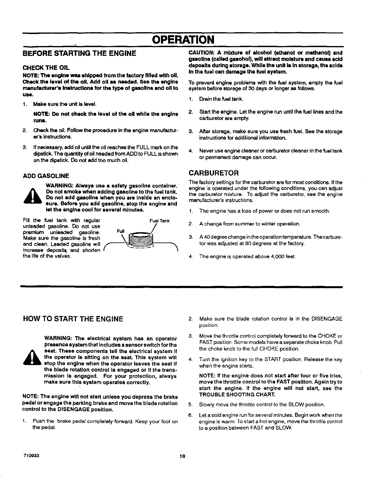
Pill the fuel tank with regular
unleaded gasoline. Do not use
premium unleaded gasoline.
Make sure the gasoline is fresh
and clean. Leaded gasoline will
increase deposits; and shorten
the life ofthe valves.
Full
\
Fue] Tank
CARBURETOR
The factory settingsfor the carburetor ere formost conditions.Ifthe
engine is operated under the following conditions, you can adjust
the carburetor mixture. To adjust the carburetor, see the engine
manufacturer's instructions.
1. The engine has a loss of power or does not runsmooth,
2. A change from summer towinter operation.
3. A40 degree change intheoperation temperature. The carbure-
torwas adjusted at 80 degrees at the factory.
4. The engine is operated above 4,000 feet.
HOW TO START THE ENGINE
&,
WARNING: The electrical system has an operator
presence system that Includes a sensor switch for the
seat. These components tell the electrical system if
the operator Is sitting on the seat. This system will
stop the en01ne when the operator leaves the seat if
the blade rotaUon control is engaged or if the trans-
mission Is engaged. For your protection, always
make sure this system operates correctly.
NOTE: The engine will not start unless you depress the brake
pedal or engage the parking brake and move the blade rotation
control to the DISENGAGE position.
1. Push the brake pedal completely forward. Keep your foot on
the pedal.
2.
3.
4,
5.
6.
Make sure the blade rotation control is in the DISENGAGE
position.
Move the throttle controlcompletely forward to the CHOKE or
FAST position. Some models have a separate choke knob. Pull
the choke knob to the full CHOKE position.
Turn the ignition key to the START position. Release the key
when the engine starts.
NOTE: If the engine does not start after four or five tries,
move the throttle control to the FAST position. Again try to
start the engine. If the engine will not start, see the
TROUBLE SHOOTING CHART.
Slowly move the throttle control to the SLOW position.
Let a cold engine runfor several minutes. Begin workwhen the
engine iswarm. To start a hot engine, move the throttlecontrol
toa positionbetween FAST and SLOW.
710933 18
OPERATION
OPERATING TIPS
1.
2,
3.
4.
Check the blade rotationcontrolforcorrect adjustment. Forthe
blade(s) to disengage correctly, the sdlustment must be cor-
rect.
Before you use the unit,check the oilin the engine and add oil
ifnecessary.
If the engine will not start, firstmake sure the wire is attached
tothe spark plug,
Make sure all the beltsare inside all the belt guides. Bee the in*
structions on how to remove end install the motion drive and
mower drive belts.
5.
6.
7.
8.
Beforeyou make an inspection, adjustment (except forthe car-
buretor)or repair,make sure the wire from the spark plug isdis-
connected.
For longer life ofthe batteryonelectric startmodels, charge the
battery every three months.
Use the speed controlpedal tochange the groundspeed, not
the throttlecontrol.
Belt noise can occur when the blade is engaged. This noise is
normal and does not affect the operation of the unit.
MOWING AND BAGGING TIPS
1. For a lawn to look better, check the cutting level of the mower
housing. See "How To Level The Mower Housing" in the Main-
tenance section.
2.
3.
4.
For the mower housing to cut level, make sure the tires have
the correct amount of air pressure.
Every time you use the unit, check the blade. Ifthe blade isbent
or damaged, immediately replace the blade. Also, make sure
the nut for the blade is tight.
Keep the blade(s) sharpened. Worn blades willcause the ends
of the grass to turn brown.
5. Do not cut or bag grass that is wet.Wet grass will not discharge
correctly. Let the grass dry before cutting.
6. Use the !eft side of the mower housing to trim near an obiect.
7.
8.
Discharge the cut grass onto the mowed area. The result is a
more even discharge of cut grass,
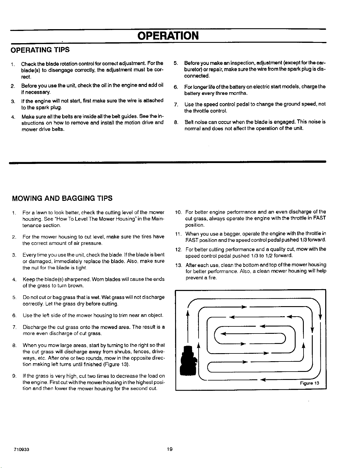
When you mow large areas, start by turningto the righl so that
the cut grass will discharge away from shrubs, fences, drive-
ways, etc. After oSe or two rounds, mow in the opposite direc-
tion making left turns until finished (Figure 13).
9. If the grass is very high, cut two timesto decrease the load on
the engine First cut withthe mowerhousing inthe highestposi-
tion and then !ower the mower housing forthe second cut.
10.
11.
12.
13.
For better engine performance and an even discharge of the
cut grass, always operate the engine with the throttle in FAST
position.
When you use a bagger, operate the engine withthe throttlein
FAST positionand thespeed controlpedal pushed 1/3 forward.
For better cuttingperformance and a quality cut, mow with the
speed control pedal pushed 1/3 to 1/2 forward.
After each use, clean the bottom and top of the mower housing
for better performance, Also, a clean mower housing will help
prevent a fire.
F
J
< J
Figure 13
71O933 19
MAINTENANCE
MAINTENANCE CHART
FIRST EVERY EVERY EVERY
EACH 2 2S ,50 100 BEFORE
PROCEDURE USE HOURS HOURS HOURS HOURS STORAGE
Bled<)Rotation Control, Check _/
O Motion Drive Belt Check _/
W
I
R Battery,Check end Charge V V
iiiiiiiiiiii_iliiii;iiiiiii;iiiiiiiiiiiiiiiiiiiii_il
[Lubrication < <
GENERAL RECOMMENDATIONS
1. The owner's responsibilityisto maintain this product. This will _ WARNING: Before you make an inspection, adjust-
extend the lifeof the product and is also necessary tomaintain _J_, ment, or repair to the unit, disconnect the wire to the
warranty coverage. _ spark plug. Remove the wire from the spark plug to
2. Check the spark plug, drive brake, lubricate the unit,and clean prevent the engine from starting by accident.
the airfilter once a year.
3. Check the fasteners. Make sure all fasteners are tight, NOTE: Torque is measured in foot pounds (metric Nm). This
4, FollowtheMaintenancesectiontokeeptheunitingoodoperat- measurement describes how tight a nut or bolt must be. The
ing condition, torque is measured with a torque wrench.
HOW TO CHECK THE MUFFLER
Check the mufflerevery 50 hours. Make sure the muffler iscorrectly
mounted and is not loose. Ifthe mufflerisworn or burnt,replace with
a new muffler. Aworn muffler is afire hazard and can also damage
the engine.
If you mount a spark arrester to the muffler, also check the spark
arrester when you check the muffler. If the spark arrester is worn or
damaged, replace it with a new spark arrester. See your nearest
authorized service center for a spark arrester.
710933 20
MAINTENANCE
INSPECT BLADE
WARNING: Before you Inspect or remove the blade,
disconnect the wire to the spark plug, Ifthe blade hifs
d_lb an object, stop the engine. Check the unit for dam-
age. The blade has sharp edges. When you hold the
blade, use gloves or cloth material to protect your
hands.
If you keep the blade sharp and inspectthe blade for damage, the
blade willcut better and be more safe tooperate, Frequently check
the blade forexcessive wear, cracks, or other damage, Frequently
check the nut that holds the blade. Keep the nuttight. If the blade
hitsan object, stopthe engine. Disconnectthe wire tothespark plug.
See ifthe blade is bent or damaged. Check the blade adapter for
damage, Before you operate the unit, replace damaged parts with
original equipment parts, See the authorized service center inyour
area, Every three years, have an authorizedservice person inspect
the blade or replace the old blade withan originalequipment pad.
HOW TO REMOVE AND INSTALL THE BLADE
1. Remove the mower housing. See the instructionson "How To
Remove The Mower Housing'.
2. Use a piece ofwood to keep the blade from rotating,
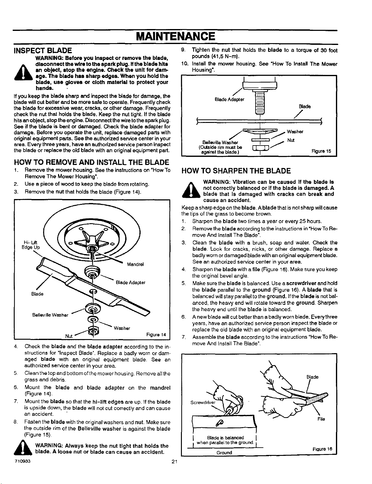
3, Remove the nut that holds the blade (Figure 14).
Hi-Lift
Edge Up
Mandrel
Blade
Blade Adapter
Belleville WaSher
Nut Figure 14
4. Check the blade and the blade adapter according to the in-
structions for "Inspect Blade". Replace a badly worn or dam-
aged blade with an original equipment blade. See an
authorized service center in your area.
5 Clean the top and bottom ofthe mower housing Remove allthe
grass and debris.
6. Mount the blade and blade adapter on the mandrel
(Figure 14).
7. Mount the blade so that the hi-lift edges are up. If the blade
is upside down, the blade will nol cut correctly and can cause
an accident.
8.
Fasten the blade withthe original washers and nut. Make sure
the outside rim of the Belleville washer is against the blade
(Figure 15).
WARNING: Always keep the nut tight that holds the
blade. A loose nut or blade can cause an accident.
21
9. Tighten the nut that holds the blade to a torque of 30 foot
pounds (41,5 N-m).
10. Install the mower housing. See "How To Install The Mower
Housing=.
BladeAdapt
Blade
/
BellevilleWaSher _ / Nut
(Outsiderimmust be E::_:_
againsttheblade.) I Figure15
HOW TO SHARPEN THE BLADE
WARNING: Vibration can be caused If the blade Is
i_5 not correctly balanced or if the blade is damaged. A
blade that Is damaged with cracks can break and
cause an accident.
Keep a sharp edge on the blade. A blade that is notsharpwill cause
the tips of the grass to become brown.
1. Sharpen the blade two times a year or every 25 hours.
2. Remove the blade according to the instructionsin =HowTo Re-
move And Install The Blade".
3. Clean the blade with a brush, soap and water, Check the
blade. Look for cracks, nicks, or other damage. Replace a
badly worn or damaged blade with an original equipment blade.
See an authorized service center in your area.
4. Sharpen the blade with afile (Figure 16). Make sure you keep
the original bevel angle.
5. Make surethe blade isbalanced. Use a screwdriver and hold
the blade parallel to the ground (Figure 16). A blade that is
balanced willstay parallel to the ground. If the blade is not bal-
anced, the heavy end will rotate toward the ground. Sharpen
the heavy end until the blade is balanced.
6. A new blade willcut better than a badly worn blade. Everythree
years, have an authorized service person inspect the blade or
replace the old blade with an original equipment blade.
7. Assemble the blade according to the instructions "How To Re-
move And Install The Blade".
Screwdriver
I Bladek balanced
whenpare e totheground. I
m
Ground
Figure 16
MAINTENANCE
HOW TO ADJUST THE BLADE ROTATION CONTROL
A ARNING: To prevent an injury, the blade rotation
control must operate correctly.
In normal usage, the blade rotation control will not require an
adjustment. However, if the cutting performance decreases or the
quality of cut is poor, make the following changes.
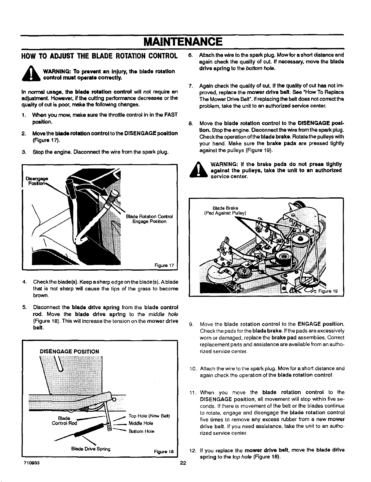
1. Whenyou mow,makesurethethrottlecontrolininthe FAST
poeition.
2. Move the blade rotation control tothe DISENGAGE position
(Figure 17).
3. Stop the engine. Disconnect the wire from the spark plug.
6. Attach the wire tothe spark plug. Mow fora shortdistance and
again check the quality of cut. If necessary, move the blade
drive spring to the bottom ho/e.
7.
Again check the quality of cut. if the quality of cut has not im-
proved, replace the mower drive belt. See "How To Replace
The Mower Drive Belt'. If replacingthe belt does not correctthe
problem, take the unitto an authorized service center.
B. Move the blade rotation control to the DISENGAGE poal.
tion. Stop the engine, Disconnect the wire from the sparkplug.
Check the operation ofthe blade brake. Rotate the pulleyswith
your hand, Make sure the brake pads are pressed tightly
against the pulleys (Figure 1B),
Blade Rotation Control
Engage Position
Figure 17
4. Check the blade(s). Keep a sharp edge onthe blade(s). A blade
that is not sharp will cause the tips of the grass to become
brown.
A
WARNING: If the brake pads do not press tightly
against the pulleys, take the unit to an authorized
service center.
Blade Brake
(Pad Against Pulley)
i iiii!i!
F_gure lg
5,
Disconnect the blade drive spring from the blade control
rod. Move the blade drive spring to the middle hole
(Figure 18). This will increase the tension onthe mower drive
belt.
DISENGAGE POSITION
Blade
Control Rod
Top Hole (New BeR)
Middle Hole
• ;ttorn Hole
Blade Ddve Spring
g.
tO.
11.
Move the blade rotation control to the ENGAGE position.
Check the padsfor theblade brake. Ifthe pads are excessively
worn or damaged, replace the brake pad assemblies. Correct
replacement partsand assistance are available from an autho-
rized service center.
Attach the wire to the spark plug. Mow for a short distance and
again check the operation of the blade rotation control.
When you move the blade rotation control to the
DISENGAGE position, all movement witl stop within five se-
conds, ff there is movement of the belt or the blades continue
to rotate, engage and disengage the blade rotation control
five times to remove any excess rubber from a new mower
drive belt. if you need assistance, take the unitto an autho-
rized service center.
Figure t8 12. If you replace the mower drive belt, move the blade drtve
spring to the top hole (Figure 18).
710933 22
MAINTENANCE
HOW TO CHECK AND ADJUST THE DRIVE BRAKE
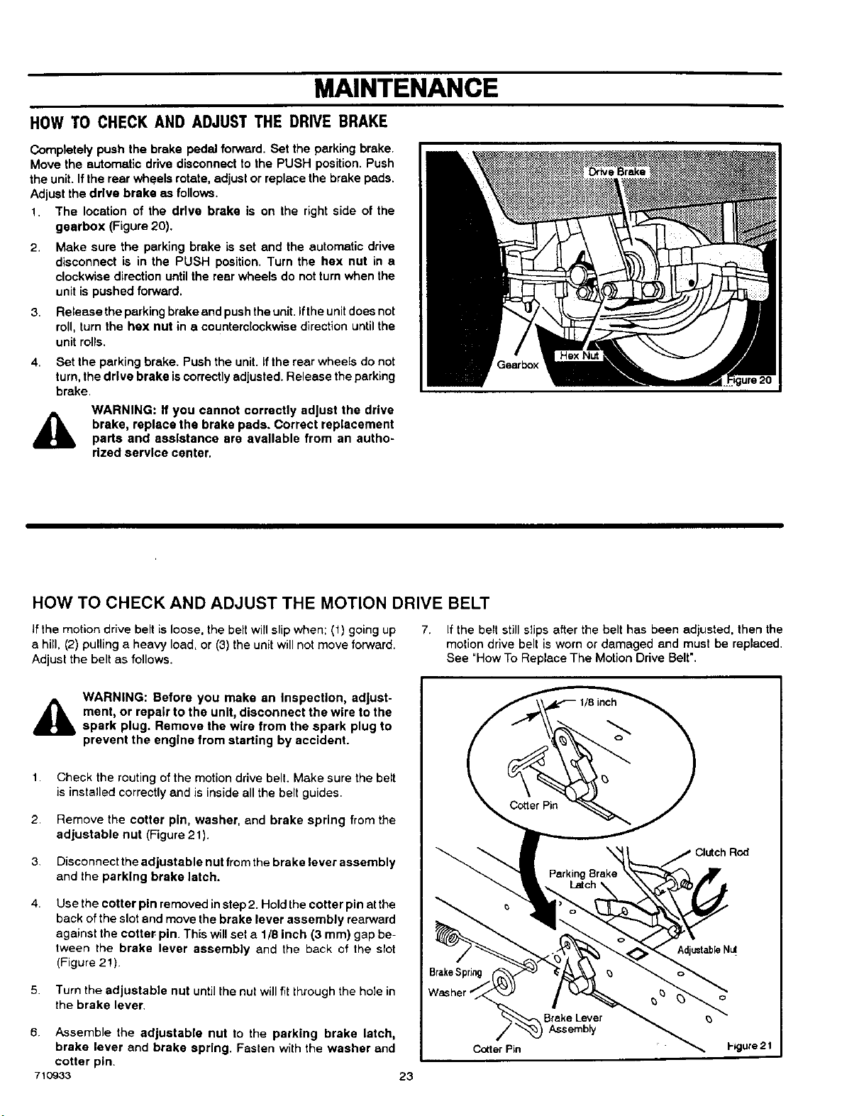
Completely push the brake pedal forward. Set the parking brake.
Move the automatic drive disconnect to the PUSH position. Push
the unit. If the rear wheels rotate, adjust or replace the brake pads.
Adjust the drive brake as follows.
1. The location of the drive brake is on the right side of the
gearbox (Figure 20).
2. Make sure the perking brake is set end the automatic drive
disconnect is in the PUSH position. Turn the hex nut in e
clockwise direction until the rear wheels do not turnwhen the
unit is pushed forward.
3.
4.
Release the parking brakeand pushthe unit.Ifthe unitdoes not
roll, turn the hex nut in a counterclockwise direction untilthe
unit rolls.
Set the parking brake. Push the unit. ifthe rear wheels do not
turn,the drive brake iscorrectlyadiusted. Release the parking
brake.
,&
WARNING: ff you cannot correctly adjust the drive
brake, replace the brake pads. Correct replacement
parts and assistance are available from an autho-
rized service center.
HOW TO CHECK AND ADJUST THE MOTION DRIVE BELT
If the motion drive belt is loose, the belt will slip when; (1) going up
a hill, (2) pulling a heavy load, or (3) the unit willnotmove forward.
Adjust the belt as follows.
7. Ifthe belt still slips after the belt has been adjusted, then the
motion drive belt is worn or damaged end must be replaced,
See "How To Replace The Motion Drive Belt'.
,&
WARNING: Before you make an Inspection, adjust-
ment, or repair to the unit, disconnect the wire to the
spark plug. Remove the wire from the spark plug to
prevent the engine from starting by accident.
1.
2.
3,
4.
Check the routingof the motion drive belt. Make sure the belt
is installed correctly and is inside all the belt guides.
Remove the cotter pin, washer, and brake spring from the
adjustable nut (Figure 21).
Disconnect the adjustable nut fromthe brake lever assembly
and the parking brake latch.
Use the cotter pin removed instep 2. Holdthe cotter pin atthe
back of the slot and move the brake lever assembly rearward
against the cotter pin. This will set a 1/8 inch (3 mm) gap be-
tween the brake lever assembly and the back of the slot
(Figure 2!)
5. Turn the adjustable nut until the nut willfitthrough the hole in
the brake lever.
6. Assemble the adjustable nut to the parking brake latch,
brake lever and brake spring. Fasten with the washer and
cotter pin.
710933 23
Brake Lever
Assembly
Cotter Pin I-_gure 21
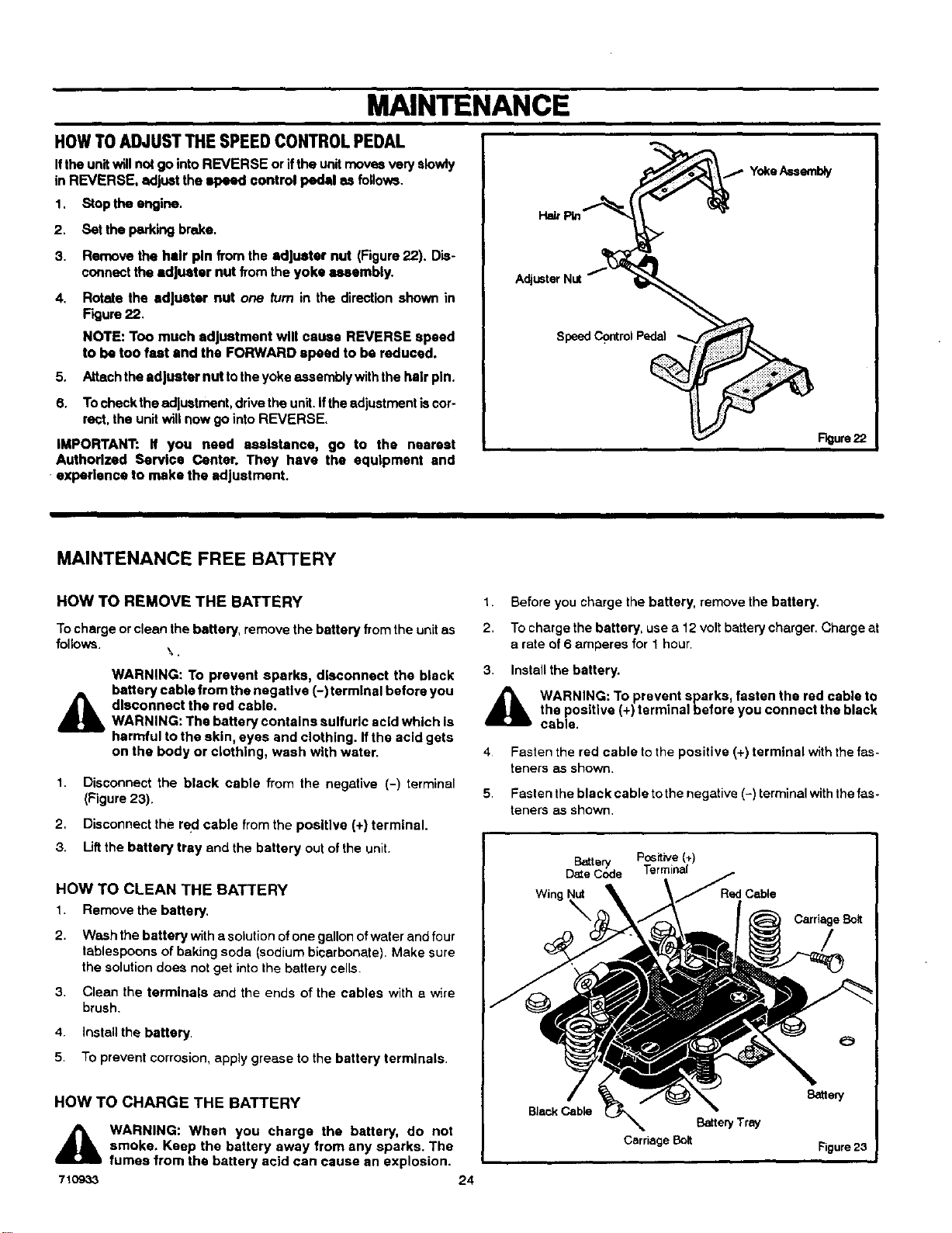
MAINTENANCE
HOWTOADJUST THESPEED CONTROLPEDAL
Ifthe unitwill not go into REVERSE or ifthe unitmoves very slowly
in REVERSE, adjust the speed control pedal as follows.
1. Stop the engine.
2. Set the parking brake.
3. Remove the hair pin from the adjuster nut (Figure 22). Dis-
connect the adjuster nut from the yoke assembly.
4. Rotate the adjuster nut one turn in the direction shown in
Figure 22.
NOTE: Too much adjustment will cause REVERSE speed
to be too fast end the FORWARD speed to be reduced.
5. Attachthe adjuster nut to the yoke assembly with the hair pin.
6. Tocheck the adjustment, drive the unit.ifthe adjustment iscor.
feet, the unit will now go into REVERSE.
IMPORTANT: If you need assistance, go to the nearest
Authorized Service Center. They have the equipment and
expedsnce to make the adjustment.
Hair
Speed Control Pedal
F_urs 22
MAINTENANCE FREE BATTERY
HOW TO REMOVE THE BATTERY
Tocharge or clean the battery, remove the battery fromthe unitas
follows.
WARNING: To prevent sparks, disconnect the black
battery cable from the negative (-) terminal before you
disconnect the red cable.
WARNING: The battery contains sulfuric acid which is
harmful to the skin, eyes and clothing. If the acid gets
on the body or clothing, wash with water.
1. Disconnect the black cable from the negative (-) terminal
(Figure 23).
2, Disconnect the recl cable from the positive (+) terminal.
3. Liftthe battery tray and the battery out of the unit.
HOW TO CLEAN THE BATTERY
1. Remove the battery.
2. Wash the battery with asolution ofone gallon ofwater and four
tablespoons of baking soda (sodium bicarbonate). Make sure
the solution does notget intothe battery cells.
3. Clean the terminals and the ends of the cables with a wire
brush.
4. Install the battery
5, To prevent corrosion, apply grease to the battery terminals
HOW TO CHARGE THE BATTERY
71O933
WARNING: When you charge the battery, do not
smoke. Keep the battery away from any sparks. The
fumes from the battery acid can cause an explosion.
24
1. Before you charge the battery, remove the battery.
2. Tocharge the battery, use a 12 volt batterycharger. Charge at
a rate of 6 amperes for 1 hour.
3 Install the battery.
_lb WARNING: To prevent sparks, fasten the red cable to
the positive (+) terminal before you connect the black
cable.
4
5
Fasten the red cable to the positive (+) terminal with the fas-
teners as shown.
Fasten the black cable tothe negative (-) terminal withthe fas-
teners as shown,
Pc6itive (+)
I
Carriage Bolt
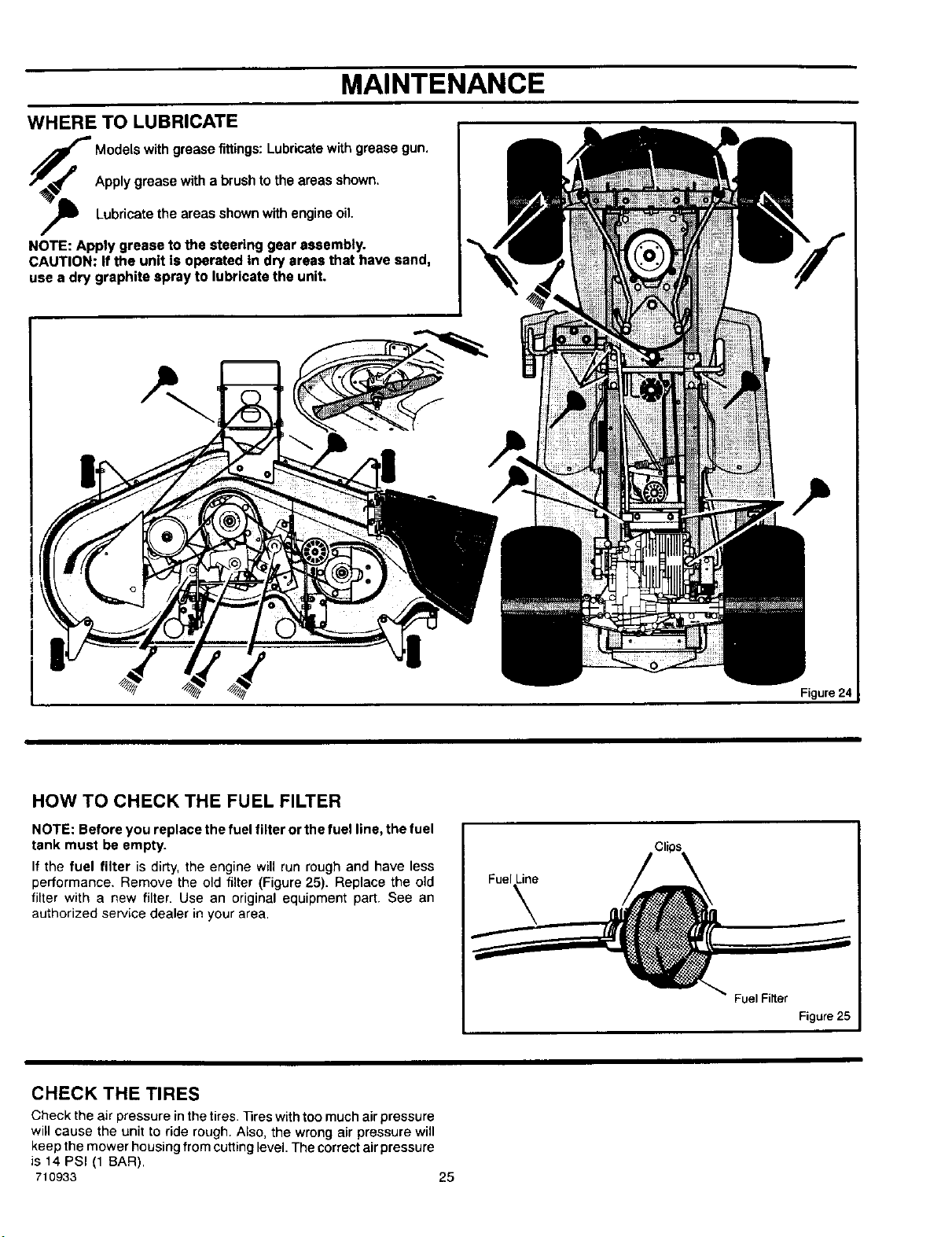
MAINTENANCE
WHERE TO LUBRICATE
/_p Models with grease fittings: Lubricate with grease gun.
/J_,_ Apply grease with a brush to the areas shown.
,_ Lubricate the areas shownwith engine oil.
NOTE: Apply grease to the steering gear assembly.
CAUTION: If the unit is operated in dry areas that have sand,
use a dry graphite spray to lubricate the unit.
Figure 24
HOW TO CHECK THE FUEL FILTER
NOTE: Before you replace the fuel filter or the fuel line, the fuel
tank must be empty.
If the fuel filter is dirty, the engine will run rough and have less
performance. Remove the old filter (Figure 25). Replace the old
filter with a new filter. Use an original equipment part. See an
authorized service dealer in your area.
Fuel Line
Fuel Filter
Figure 25
CHECK THE TIRES
Check the air pressure in the tires. 33res with too much air pressure
will cause the unit to ride rough. Also, the wrong air pressure will
keep the mower housing from cutting level. The correct air pressure
is 14 PSI (1 BAR).
710933 25
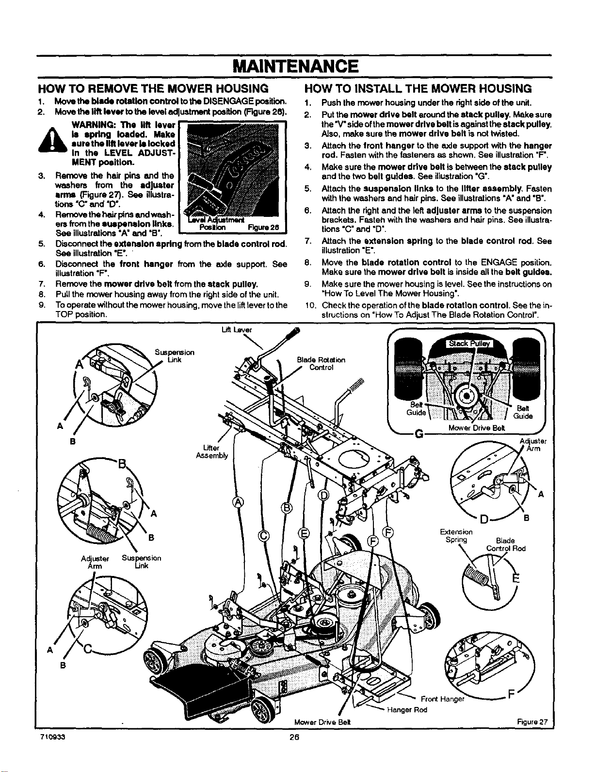
MAINTENANCE
HOW TO INSTALL THE MOWER HOUSINGHOW TO REMOVE THE MOWER HOUSING
1. Move the blade rotation €ontrol tothe DISENGAGE position.
2. Move the tilt lever tothe level adjustment position(Figure 26).
WARNING: The lift lever
d_lb le spring loaded. Makesure the lilt lover II locked
In the LEVEL ADJUST-
MENT position.
3. Remove the hair pins and the
washers from the adjuster
ernw (Figure 27). See illustra-
tions "C"and "D'.
4. Remove the hairpins and wssh-
ars fromthe euapermlon links.
See illustrations =A"and =B'.
5. Disconnect the extension spring fromthe blade control rod.
See illustration"E'.
6. Disconnect the front hanger from the axle support. See
illustration"F'.
7. Remove the mower drive belt from the stack pulley.
8. Pull the mower housing away from the rightside of the unit.
9. Tooperate Without the mower housing, movethe liftlever tothe
TOP position.
Lift Lever
\
Lifter
Assemb_
A_rUSter Sus_..n_Si°n
B
710933
1. Push the mower housing under the rightside of the unit.
2. Put the mower drive belt around the stack pulley. Make sure
the'V" side ofthe mower drive belt isagainstthe stack pulley.
Also. make sure the mower drive belt is nottwisted.
3. Attach the front hanger to the axle support with the hanger
rod. Fasten withthe fasteners as shown. See illustration"F".
4. Make sure the mower drive belt isbetween the stack pulley
and the two belt guides. See illustration"G'.
5. Attach the suspension links to the lifter aSSembly. Fasten
with the washers and hair pins. _P,ee illustrations"A"and "B'.
6. Attach the rightand the left adjuster arms to the suspension
brackets. Fasten with the washers and hair pins. See illustra-
tions "C"and "D'.
7. Attach the extension spring to the blade control rod. See
illustration"E'.
8. Move the blade rotation control to the ENGAGE position,
Make sure the mower drive belt is inside all the belt gulde,s.
9. Make sure the mower housing is level. See the instructionson
*How To Level The Mower Housing'.
10. ChecktheoperationofthebladerotatloncontroI. Seethein-
structionson "HowTo AdjustThe Blade Rotation Control'.
Blade Rotation
Control
Mower Drive Belt
26
Hanger Rod
G MowerDriveBelt
A uster
Extension
Spring Blade
F
Figure27
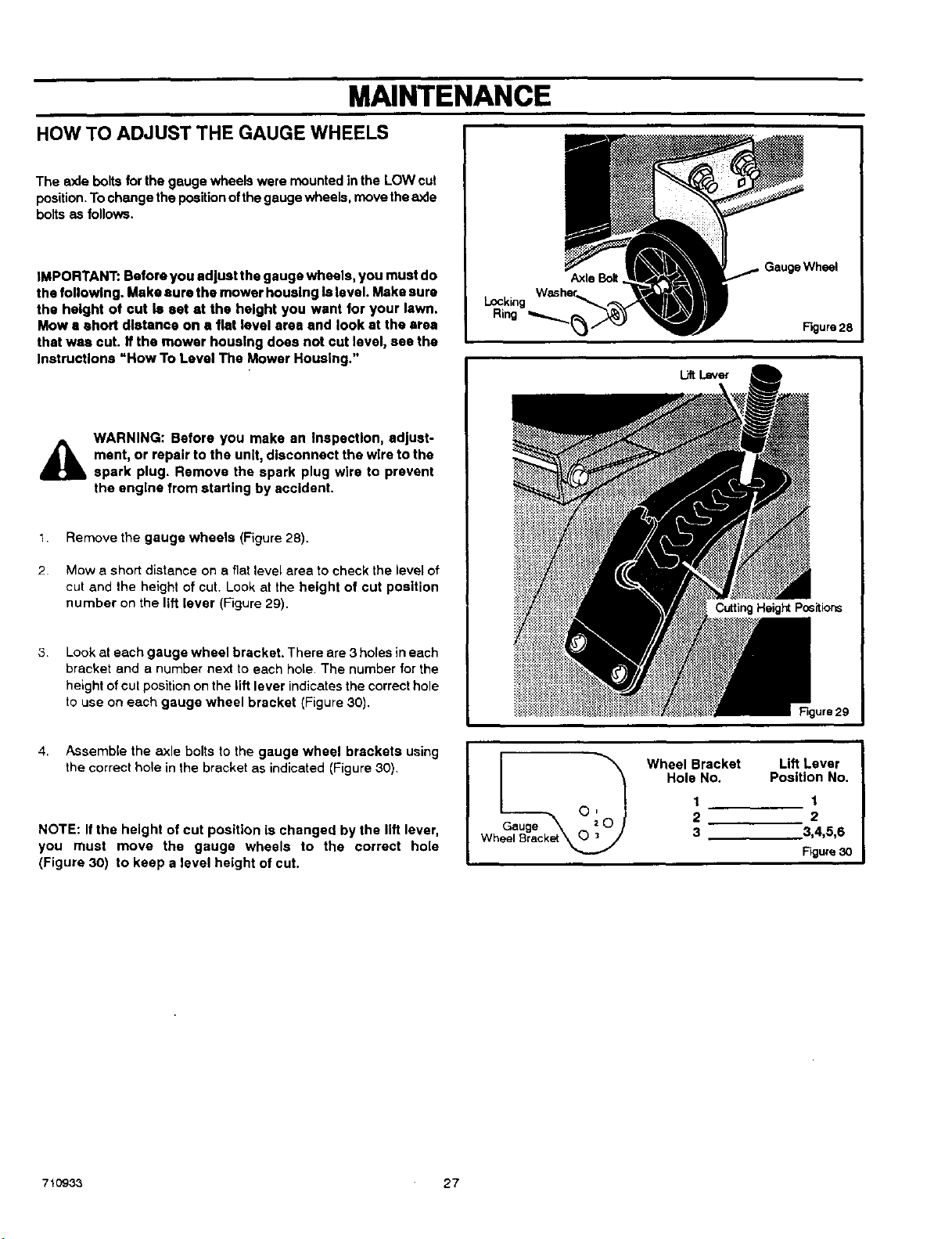
MAINTENANCE
HOW TO ADJUST THE GAUGE WHEELS
The rode bolts for the gauge wheels were mounted in the LOW cut
position.Tochange the positionofthe gauge wheels, move theaxle
bolts as follows.
IMPORTANT: Before you adjust the gauge wheels, you must do
the following. Make sure the mower housing Is level. Make sure
the height of cut 18set at the height you want for your lawn.
Mow a short distance on a flat level area and look at the area
that was cut. If the mower housing does not cut level, see the
Instructions "How To Level The Mower Housing."
WARNING: Before you make an Inspection, adjust-
i_jl ment, or repair to the unit, disconnect the wire to the
spark plug. Remove the spark plug wire to prevent
the engine from starting by accident.
I. Remove the gauge wheels (Figure 28).
2 Mow a short distance on a fiat level area to check the level of
cut and the height of cut. Look at the height of cut position
number on the lift lever (Figure 29).
3
Look at each gauge wheel bracket. There are 3 holes in each
bracket and a number next to each hole. The number for the
height ofcut positionon the lift lever indicatesthe correcthole
to use on each gauge wheel bracket (Figure 30).
Locking
Ring
Axle Bolt
e Wheel
Rgure 28
Cutting Height Positions
Figure 29
4. Assemble the axle bolts to the gauge wheel brackets using
the correct hole in the bracket as indicated (Figure 30).
NOTE: If the height of cut position is changed by the lift lever,
you must move the gauge wheels to the correct hole
(Figure 30) to keep a level height of cut.
auge 0 _0
Wheel Brac_
Wheel Bracket Lift Lever
Hole No. Position No.
1 1
2 2
3 3,4,5,6
Figure30
71093-3 27
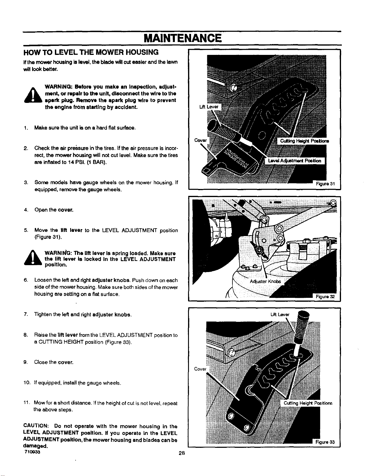
MAINTENANCE
HOW TO LEVEL THE MOWER HOUSING
Ifthe mower housing is level, the blade will cut easier and the lawn
will look better.
WARNING: Before you make an Inspection, edjust-
_lb ment, or repair to the unit, disconnect the wire to the
Ipark plug. Remove the spark plug wire to prevent
the engine from starting by accident.
1. Make sure the unitis on a hard flat surface.
2. Check the air pressure in the tires. If the air pressure is incor-
rect, the mower housing will not cut level. Make sure the tires
are inflated to 14 PSi. (1 BAR).
3. Some models have gauge wheels on the mower housing. If
equipped, remove the gauge wheels.
LiftLever
Figure 31
4, Open the cover.
5. Move the lift lever to the LEVEL ADJUSTMENT position
(Figure 31).
A WARNIN_G:The lift lever Is spring loaded. Make sure
the lift lever Is locked In the LEVEL ADJUSTMENT
position.
6. Loosen the left end rightadjuster knobs. Push down oneach
side ofthe mower housing. Make sure both sidesofthe mower
housing are setting on e fiat surface.
7. Tighten the left end rightadjuster knobs.
8. Raise the lift lever from the LEVEL ADJUSTMENT position to
e CUTTING HEIGHT position (Figure 33).
9. CIosethe cover.
10. If equipped, install the gauge wheels.
11. Mow fora short distance. If the height of cut isnot level, repeat
the above steps.
CAUTION: Do not operate with the mower housing in the
LEVEL ADJUSTMENT position. If you operate in the LEVEL
ADJUSTMENT posiflon, the mower housing and blades can be
damaged.
710033 28
Cove,
Lift Lever
Cutting Height Positions
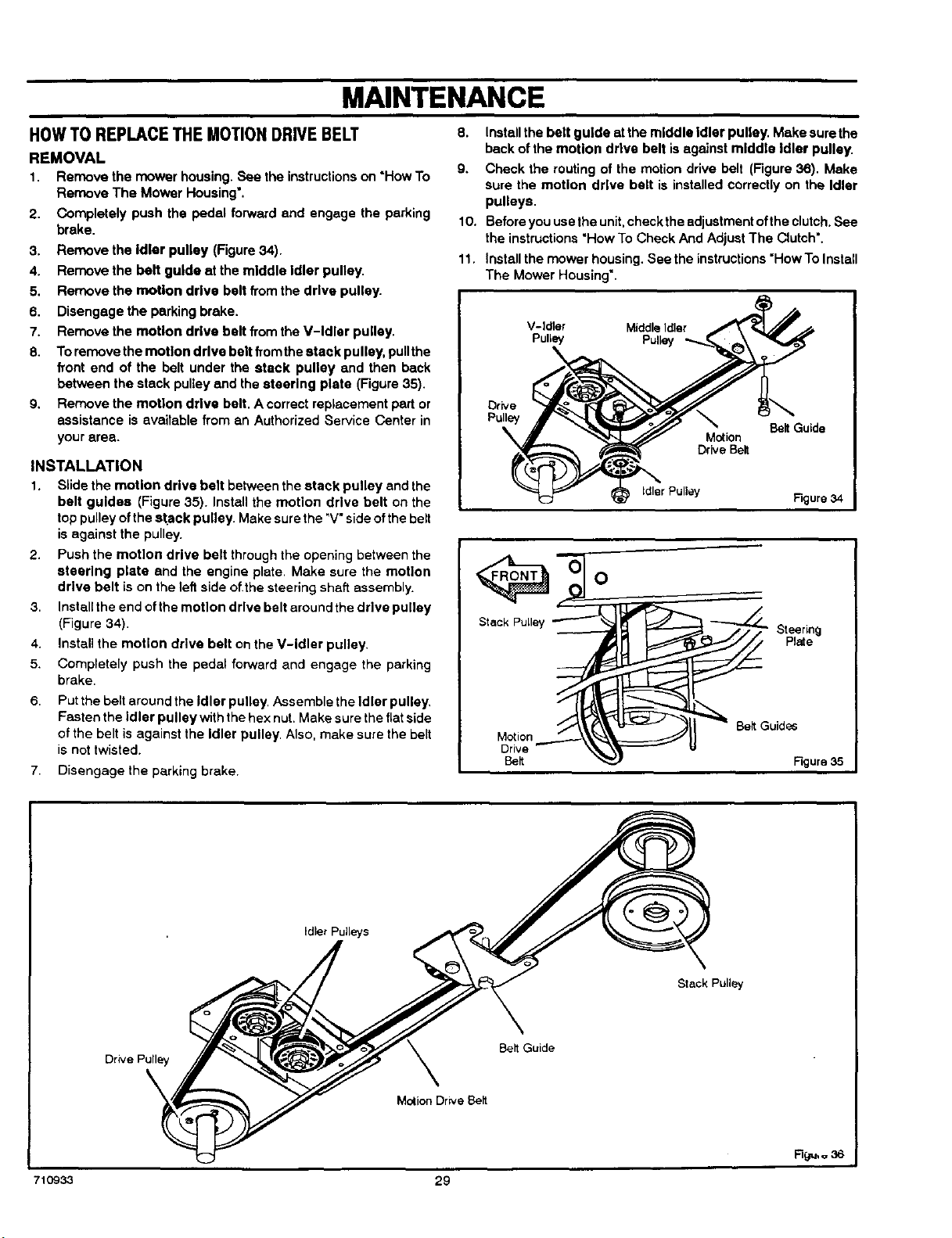
MAINTENANCE
HOWTO REPLACETHE MOTIONDRIVEBELT
REMOVAL
1. Remove the mower housing. See the instructionson "HowTo
Remove The Mower Housing'.
2. Completely push the pedal forward and engage the parking
brake.
3. Remove the Idler pulley (Figure 34).
4. Remove the belt guide at the middle Idler pulley.
5. Remove the motion drive belt from the drive pulley.
6. Disengage the parking brake.
7. Remove the motion drive belt from the V-Idler pulley.
8. Toremove the motion drive belt from the stack pulley, pullthe
front end of the belt under the stack pulley and then back
between the stack pulteyand the steering plate (Figure 35).
9. Remove the motion drive belt. A correct replacernent part or
assistance is available from an Authorized Service Center in
your area.
INSTALLATION
1. Slide the motion drive belt between the stack pulley and the
belt guides (Figure 35). Install the motion drive belt on the
top pulleyofthe stack pulley. Make surethe 'V" sideofthe belt
isagainst the pulley.
2. Push the motion drive belt through the opening between the
steering plate and the engine plate. Make sure the motion
drive belt is on the left side of the steering shaft assembly.
Installthe end ofthe motion drive belt around the drive pulley
(Figure 34).
Install the motion drive belt on the V-Idler pulley.
Completely push the pedal forward and engage the parking
brake.
3.
4.
5.
6.
Put the belt around the Idler pulley, Assemble the Idler pulley.
Fasten the Idler pulley withthe hex nut. Make sure the flat side
ofthe belt is against the Idler pulley. Also, make sure the belt
isnot twisted.
7. Disengage the parking brake.
8. Install the belt guide atthe middle Idler pulley. Make sure the
back of the motion drive belt isagainst middle Idler pulley.
9. Check the routing of the motion drive belt (Figure 36). Make
sure the motion drive belt is installed correctly on the Idler
pulleys.
10. Before you use the unit,check theadjustment ofthe clutch.See
the instructions"How To Check And Adjust The Clutch'.
11. Install the mower housing.See the instructions"HowTo Install
The Mower Housing'.
V-idler MiddleIdler
Pulley PuUey
\
Drive
Pulley
Motion
Drive Belt
Belt Guide
idler Pulley Figure 34
Steering
Plate
BeltGuides
Figure 35
Idler Pulleys
Stack Pulley
Drive Pulley
Belt Guide
MotionDriveBelt
710933 29
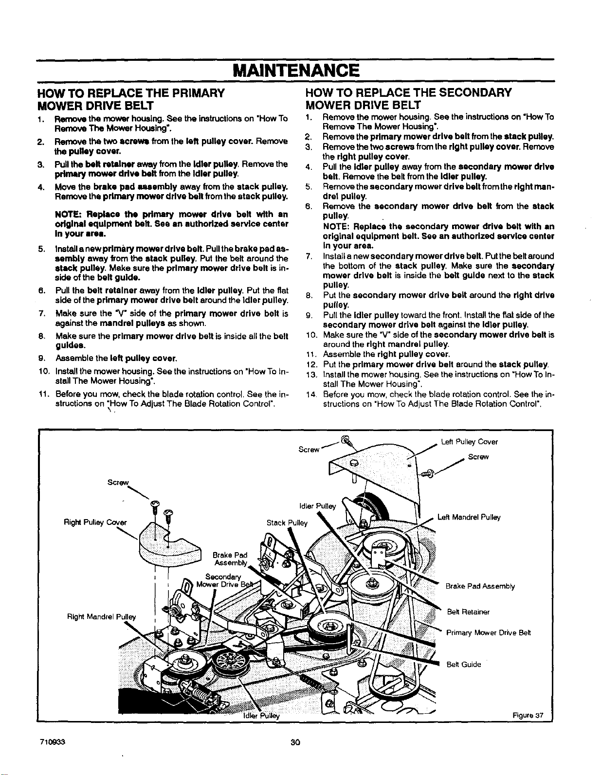
MAINTENANCE
HOW TO REPLACE THE PRIMARY
MOWER DRIVE BELT
1. Remove the mower housing. _ the instructionson "HowTo
Remove The Mower Housing'.
2. Remove the two _rews from the left pulley cover. Remove
the pulley cover.
3. Pullthe belt retainer away from the idler pulley, Remove the
primly mower ddve belt fromthe Idler pulley,
4. Move the brake pad membly sway from the stack pulley.
Remove the primary mower drive belt from the stack pulley.
NOTE: Replace the pdmary mower drive belt with an
original equipment belt. See an authorized service center
In your are-,.
5. Install s newprlm_,ry mower drive belt. Pullthe brake pad as-
sembly away from the stack pulley. Put the belt around the
stack pulley. Make sure the primary mower drive belt is in.
side ofthe belt guide.
6. Pull the belt retainer away from the Idler pulley. Put the fiat
side ofthe primary mower ddve belt around the idler pulley.
7. Make sure the "V" side of the primary mower drive belt is
against the mandrel pulleys as shown.
8. Make sure the primary mower drive belt is inside all the belt
guides.
9. Assemble the left pulley cover.
10. Installthe mower housing. See the instructions on "HowTo In-
stall The Mower Housing'.
11. Before you mow, check the blade rotation control. See the in-
structions on "How To Adjust The Blade Rotation Control'.
\.
HOW TO REPLACE THE SECONDARY
MOWER DRIVE BELT
1. Remove the mower housing. See the instructionson "HowTo
Remove The Mower Housing'.
2. Remove the primary mower drive belt from the stack pulley.
3. Remove the twoscrews from the right pulley cover. Remove
the dght pulley cover.
4. Pull the Idler pulley away from the secondary mower drive
belt. Remove the belt from the Idler pulley.
5. Remove the secondary mower drive belt from the right man-
drel pulley.
6. Remove the secondary mower drive belt from the stack
pulley.
NOTE: Replace the secondary mower drive belt with an
original equipment belt. See an authorized service center
in your area.
7. Install snew secondary mower drive belt. Put the belt around
the bottom of the stack pulley. Make sure the secondary
mower drive belt is inside the belt guide next to the stack
pulley.
8, Put the secondary mower drive belt around the right drive
pulley.
g. Pullthe idler pulley toward the front, installthe fiat side of the
secondary mower drive belt against the Idler pulley.
10. Make sure the "V"side of the secondary mower ddve bait is
around the right mandrel pulley.
11. Assemble the right pulley cover.
12. Put the primary mower drive belt around the stack pulley.
13. Install the mower housing. See the instructionson "HowTo In-
stall The Mower Housing'.
14. Before you mow, check the blade rotation control. See the in-
structionson "HowTo AdjustThe Blade Rotation Control'.
Left Pulley Cover
Screw
RightPulleyCover
Brake Pad
Left Mandrel Pulley
Brake Pad Assembly
Right Mandrel Pulley
Belt Retainer
Primary Mower Drive Belt
Belt Guide
Figure 37
710933 30
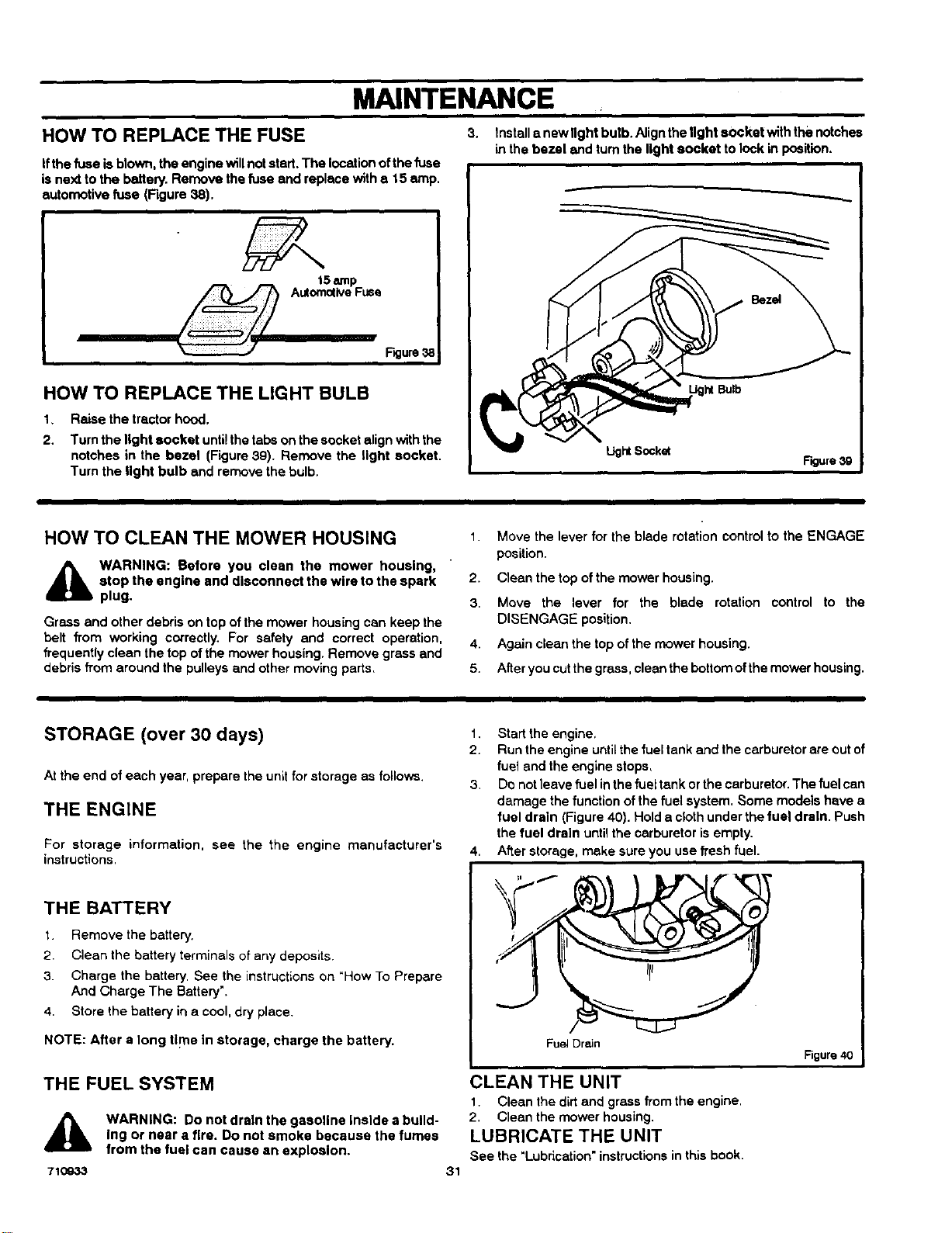
MAINTENANCE
HOW TO REPLACE THE FUSE
ifthe fuse isblown, the engine willnot start. The locationofthe fuse
isnext to the battery. Remove the fuse and replace with e 15 amp.
automotive fuse (Rgure 38).
HOW TO REPLACE THE LIGHT BULB
2.
Raise the tractor hood.
Turn the light socket unti!the tabs onthe socket align with the
notches in the bezel (Figure 39). Remove the light socket.
Turn the light bulb and remove the bulb.
3. Install a newllght bulb. Alignthe light socket withthe notches
in the bezel and turnthe light socket to lock in position.
LightSocket
Figure 3g
HOW TO CLEAN THE MOWER HOUSING
_b WARNING: Before you clean the mower housing,
stop the engine and disconnect the wire to the spark
plug.
Grass and other debris on topof the mower housing can keep the
belt from working correctly. For safety and correct operation.
frequently clean the top of the mower housing. Remove grass and
debris from around the pulleysand other moving parts,
1. Move the lever for the blade rotation control to the ENGAGE
position.
2. Clean the top of the mower housing.
3. Move the lever for the blade rotation control to the
DISENGAGE position.
4. Again clean the top of the mower housing.
5. After you cut the grass, clean the bottom of the mower housing.
STORAGE (over 30 days)
At the end of each year, prepare the unit for storage as follows.
THE ENGINE
For storage information, see the the engine manufacturer's
instructions.
THE BATTERY
1 Remove the battery.
2. Clean the battery terminals of any deposits.
3. Charge the battery. See the instructionson "How To Prepare
And Charge The Battery'.
4. Store the battery in a cool, dry place.
NOTE: After a long tlF=ein storage, charge the battery.
THE FUEL SYSTEM
71O933
WARNING: DOnot drain the gasoline Inside a build-
Ing or near a fire. Do not smoke because the fumes
from the fuel can cause an explosion.
31
1. Start the engine,
2. Run the engine untilthe fuel tank and the carburetor are outof
fuel and the engine stops,
3. Do not leave fuel inthe fuel tankor the carburetor.The fuel can
damage the function of the fuel system. Some models have a
fuel drain (Figure 40). Hold a cloth underthe fuel drain. Push
the fuel drain untilthe carburetor is empty.
4. After storage, make sure you use fresh fuel.
Fuel Drain
Figure 40
CLEAN THE UNIT
1. Clean the dirtand grassfrom the engine.
2. Clean the mower housing.
LUBRICATE THE UNIT
See the "Lubrication" instructionsinthis book.
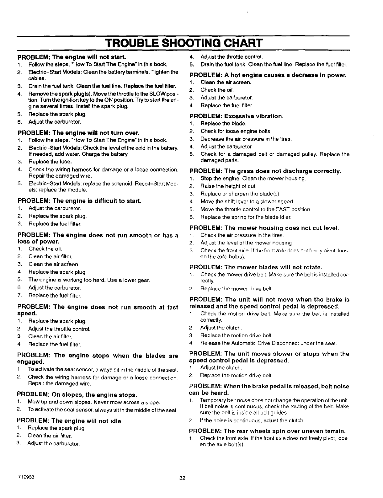
TROUBLE SHOOTING CHART
PROBLEM: The engine will not start,
1. Follow the steps, "How To Start The Engine" in thisbook.
2. Electric-Start Models: Clean the battery terminals. Tighten the
cables.
3. Drain the fuel tank. Clean the fuel line. Replace the fuel filter.
4. Remove the spark plug(s). Move the throttletothe SLOW posi-
tion.Turn the ignitionkey to the ON position. Try tostart the en-
gine several times. Installthe spark plug.
5. Replace the spark plug.
6. Adjust thecerbumtor.
PROBLEM: The engine will not turn over.
1. Follow the steps, "HowTo Start The Engine" in thisbook.
2. Electric-Start Models: Check the level ofthe acid inthe battery.
Ifneeded, add water. Charge the battery.
3. Replace the fuse.
4. Check the wiring harness for damage or a loose connection.
Repair the damaged wire.
5. Etectric-Stad Models: reptacethe solenoid. Recoil-Start Mod-
els: replace the module.
PROBLEM: The engine is difficult to start,
1. Adjust the carburetor.
2. Replacethe spark plug.
3. Replace the fuel filter.
PROBLEM: The engine does not run smooth or has a
loss of power.
1. Check the oil.
2. Clean the air filter.
3. Clean the air scr_.en.
4. Replace the spark plug.
5. The engine is working too hard. Use a lower gear.
6. Adjust the carburetor.
7. Replace the fuel filter.
PROBLEM: The engine does not run smooth at fast
speed.
1. Replace the spark plug.
2. Adjustthe throttle control.
3. Clean the air filter.
4. Replacethe fuel filter.
PROBLEM: The engine stops when the blades are
engaged.
1. To activate the seat sensor, always sit inthe middle of the seat
2. Check the wiring harness for damage or a loose connection.
Repair the damaged wire.
PROBLEM: On slopes, the engine stops.
1. Mow up and down s!opes. Never mow across a slope
2. Toactivate Ihe seat sensor, always sit in the middle ofthe seat
PROBLEM: The engine will not idle.
1. Replace the spark plug.
2. Clean the air filter.
3. Adjustthe carburetor.
4. Adjustthe throttle control.
5. Drain the fuel tank. Clean the fuel line. Replace the fuel filter.
PROBLEM: A hot engine causes a decrease in power.
1. Clean the airscreen.
2. Check the oil.
3. Adjustthe carburetor.
4. Replace the fuel filter.
PROBLEM: Excessive vibration.
1. Replace the blade.
2. Check for loose engine bolts.
3. Decrease the air pressure in the tires.
4. Adjustthe carburetor.
5. Check for a damaged belt or damaged pulley. Replace the
damaged parts.
PROBLEM: The grass does not discharge correctly.
1. Stop the engine. Clean the mower housing.
2. Raise the height of cut.
3. Replace or sharpen the blade(s).
4. Move the shift lever to a slower speed.
5. Move the thrott{econtrol to the FAST position
6. Replace the spring for the blade idler.
PROBLEM: The mower housing does not cut level.
1 Check the air pressure in the tires.
2. Adjust the level of the mower housing
3. Check the front axle. Ifthe front axle does not freely pivot, loos-
en the axle bolt(s).
PROBLEM: The mower blades will not rotate.
1. Check the mower drive belt Make sure the belt is installed cor-
rectly.
2. Replace the mower drive belt
PROBLEM: The unit will not move when the brake is
released and the speed control pedal is depressed.
1, Check the motion drive belt. Make sure the belt is installed
correctly.
2. Adjust the clulch.
3. Replace the motion drive be{t.
4. Release the Automatic Drive Disconnect under the seat
PROBLEM: The unit moves slower or stops when the
speed control pedal is depressed.
1 Adjust the clutch.
2 Replace the motion drive belt.
PROBLEM: When the brake pedal is released, belt noise
can be heard.
1 Temporary belt noise does not change the operation of the unit
If belt noise is continuous, check the routing of the belt Make
sure the belt is inside all belt guides
2. If the noise is continuous, adjust the clutch
PROBLEM: The rear wheels spin over uneven terrain.
1 Check the front axle If the front axle does not freely pivot, loos-
en the axle bolt(s).
710933 32
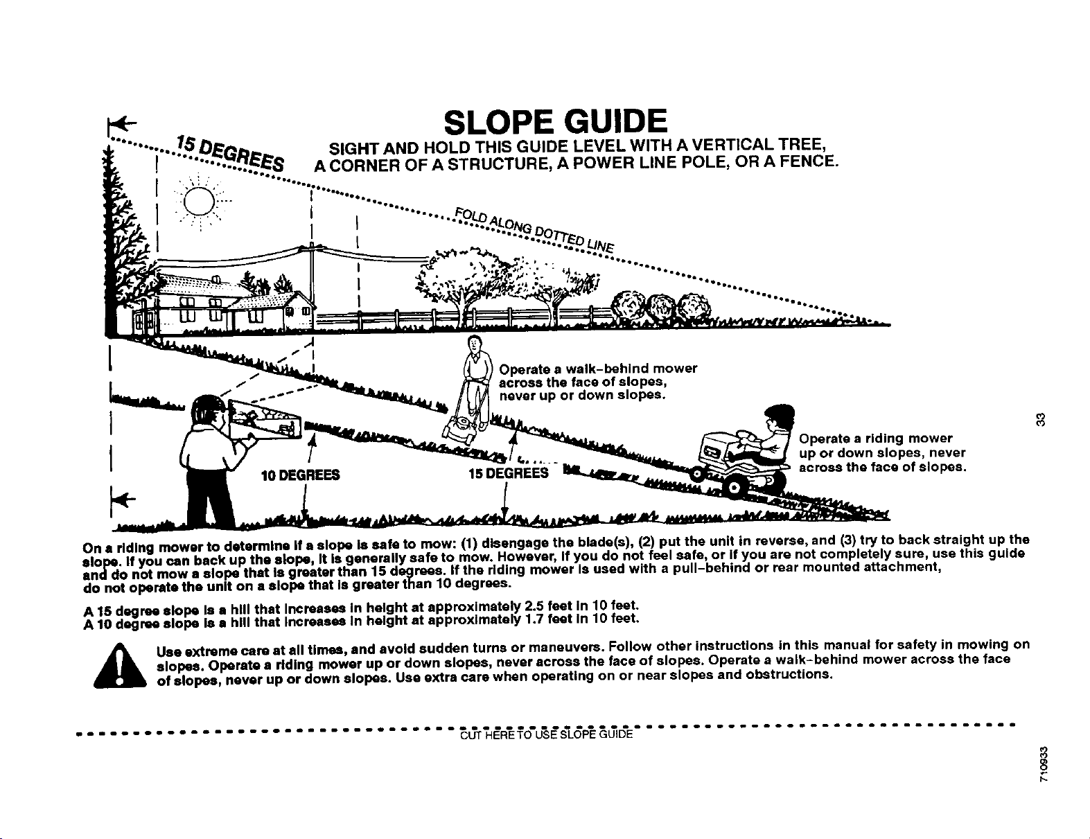
[
I
I
I
SLOPE GUIDE
Operate a walk-behind mower
across the face of slopes,
never up or down slopes.
_m I, .
10 DEGREES 15 DEGREES
a riding mower
up or down slopes, never
across the face of slopes.
co
o3
On s riding mower to determine If a slope Is safe to mow: (1) disengage the blade(s), (2) put the unit in reverse, and (3) try to back straight up the
elope. If you can back up the slope, It Is 9enerally safe to mow. However, If you do not feel safe, or if you are not completely sure, use this guide
and do not mow a slope that Is greater than 15 degrees. If the riding mower Is used with a pull-behind or rear mounted attachment,
do not operate the unit on s slope that Is greater than 10 degrees.
A 15 degree elope Is • hill that Increases In height at approximately 2.5 feet In 10 feet•
A 10 degree elope le • hill that Increase8 In height at approximately 1.7 feet In 10 feet.
A se extreme care at all times, and avoid sudden turns or maneuvers. Follow other instructions in this manual for safety in mowing on
elopes. Operate a riding mower up or down slopes, never across the face of slopes. Operate a walk-behind mower across the face
of slopes, never up or down slopes. Use extra care when operating on or near slopes and obstructions.
................................. o'u's@s'L6 .................................
h-
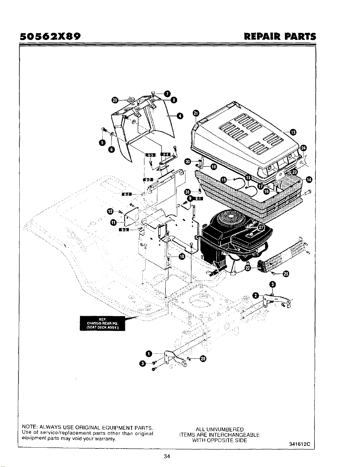
SOS62X89 REPAIR PARTS
NOTE: ALWAYS USE ORIGINAL EQUIPMENT PARTS.
Use of service/replacement parts other than original
equipment parts may void your warranty.
ALL UNNUMBERED
ITEMS ARE INTERCHANGEABLE
WITH OPPOSITE SIDE
341612C
34
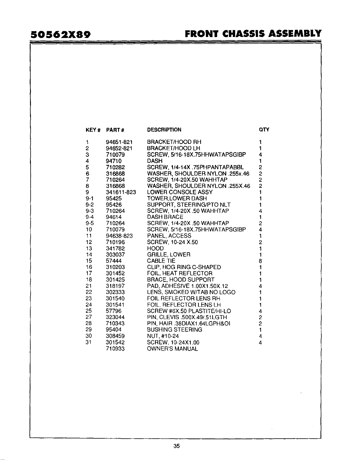
SOS62X89 FRONT CHASSIS ASSEMBLY
KEY #
1
2
3
4
5
6
7
8
9
9-1
9-2
9-3
9-4
9-5
10
11
12
13
14
15
16
17
18
21
22
23
24
25
27
28
29
30
31
PART #
94651-821
94652-821
710079
94710
710282
316868
710264
316868
341611-823
95425
95426
710264
94614
710264
710079
94638-823
710196
341782
303037
57444
310203
301452
301425
318197
302333
301540
301541
57796
323044
710343
95404
308459
301542
710933
DESCRIPTION QTY
BRACKET/HOOD RH 1
BRACKET/HOOD LH 1
SCREW, 5/16-18X.75HHWATAPSGIBP 4
DASH 1
SCREW, 1/4-14X .75PHPANTAPABBL 2
WASHER, SHOULDER NYLON .255x.46 2
SCREW, 1/4-20X.50 WAHHTAP 2
WASHER, SHOULDER NYLON .255X.46 2
LOWER CONSOLE ASSY 1
TOWER,LOWER DASH 1
SUPPORT, STEERING/PTO NLT 1
SCREW, 1/4-20X .50 WAHHTAP 4
DASH BRACE 1
SCREW, 1/4-20X .50 WAHHTAP 2
SCREW, 5/16-18X.75HHWATAPSGtBP 4
PANEL, ACCESS 1
SCREW, 10-24 X.50 2
HOOD 1
GRILLE, LOWER 1
CABLE TIE 8
CLIP, HOG RING C-SHAPED 1
FOIL, HEAT REFLECTOR 1
BRACE, HOOD SUPPORT 1
PAD, ADHESIVE 1.00X1.50X.12 4
LENS, SMOKED W/TAB NO LOGO 1
FOIL REFLECTOR LENS RH 1
FOIL, REFLECTOR LENS LH 1
SCREW #6X.50 PLASTITE/HI-LO 4
PIN, CLEVIS .500X.49/.51LGTH 2
PiN, HAIR .38DIAX1.64LGPH&OI 2
BUSHING STEERING 1
NUT, #10-24 4
SCREW, 10-24X1.00 4
OWNER'S MANUAL
35

SOS62X89 REPAIR PARTS
r
I
REF.
KEY#1
NOTE: ALWAYS USE ORIGINAL EQUIPMENT PARTS.
Use of service/replacement parts other than original
equipment parts may void your warranty
ALL UNNUMBERED
ITEMS ARE INTERCHANGEABLE
WITH OPPOSITE SIDE
341674
36
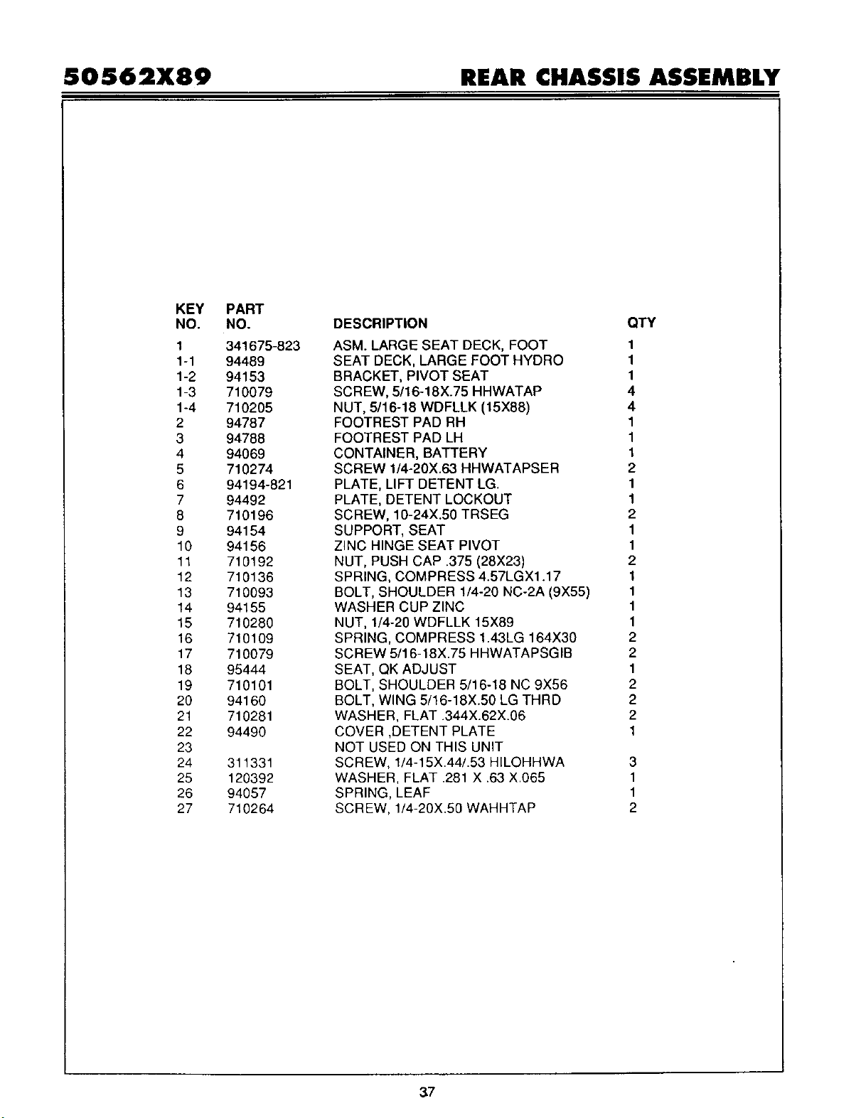
S0562X89 REAR CHASSIS ASSEMBLY
KEY
NO.
1
1-1
1-2
1-3
1-4
2
3
4
5
6
7
8
9
10
11
12
13
14
15
16
17
18
19
2O
21
22
23
24
25
26
27
PART
NO.
341675-823
94489
94153
710079
710205
94787
94788
94069
710274
94194-821
94492
710196
94154
94156
710192
710136
710093
94155
710280
710109
710079
95444
710101
94160
710281
94490
311331
120392
94057
710264
DESCRIPTION
ASM. LARGE SEAT DECK, FOOT
SEAT DECK, LARGE FOOT HYDRO
BRACKET, PIVOT SEAT
SCREW, 5/16-18X.75 HHWATAP
NUT, 5/16-18 WDFLLK (15X88)
FOOTREST PAD RH
FOOTREST PAD LH
CONTAINER, BATTERY
SCREW 1/4-20X.63 HHWATAPSER
PLATE, LIFT DETENT LG.
PLATE, DETENT LOCKOUT
SCREW, 10-24X.60 TRSEG
SUPPORT, SEAT
ZINC HINGE SEAT PIVOT
NUT, PUSH CAP .375 (28X23)
SPRING, COMPRESS 4.57LGX1.17
BOLT, SHOULDER 1/4-20 NC-2A (9X55)
WASHER CUP ZINC
NUT, 1/4-20 WDFLLK 15X89
SPRING, COMPRESS 1.43LG 164X30
SCREW 5/16-18X.75 HHWATAPSGIB
SEAT, QK ADJUST
BOLT, SHOULDER 5/16-18 NC 9X56
BOLT, WING 5/16-18X.50 LG THRD
WASHER, FLAT .344X.62X.06
COVER ,DETENT PLATE
NOT USED ON THIS UNIT
SCREW, 1/4-15X.44/.53 HILOHHWA
WASHER, FLAT .281 X .63 X.065
SPRING, LEAF
SCREW, 1/4-20X.50 WAHHTAP
QTY
1
1
1
4
4
1
1
1
2
1
1
2
1
1
2
1
1
1
1
2
2
1
2
2
2
1
3
1
1
2
37
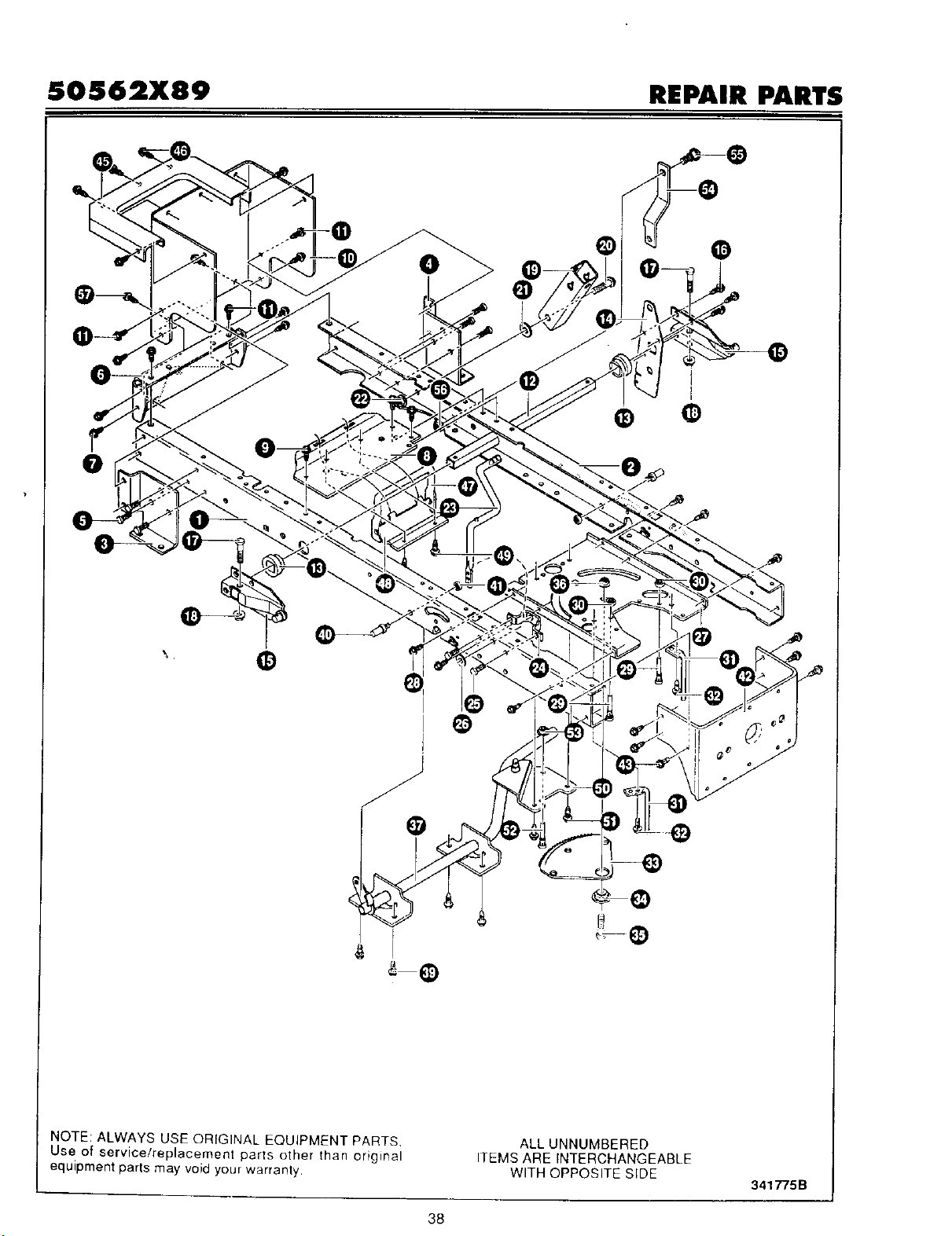
SOS62X89 REPAIR PARTS
NOTE: ALWAYS USE ORIGINAL EQUIPMENT PARTS
Use of service/replacement parts other than original
equipment parts may void your warranty.
ALL UNNUMBERED
ITEMS ARE INTERCHANGEABLE
WITH OPPOSITE SIDE
341775B
38
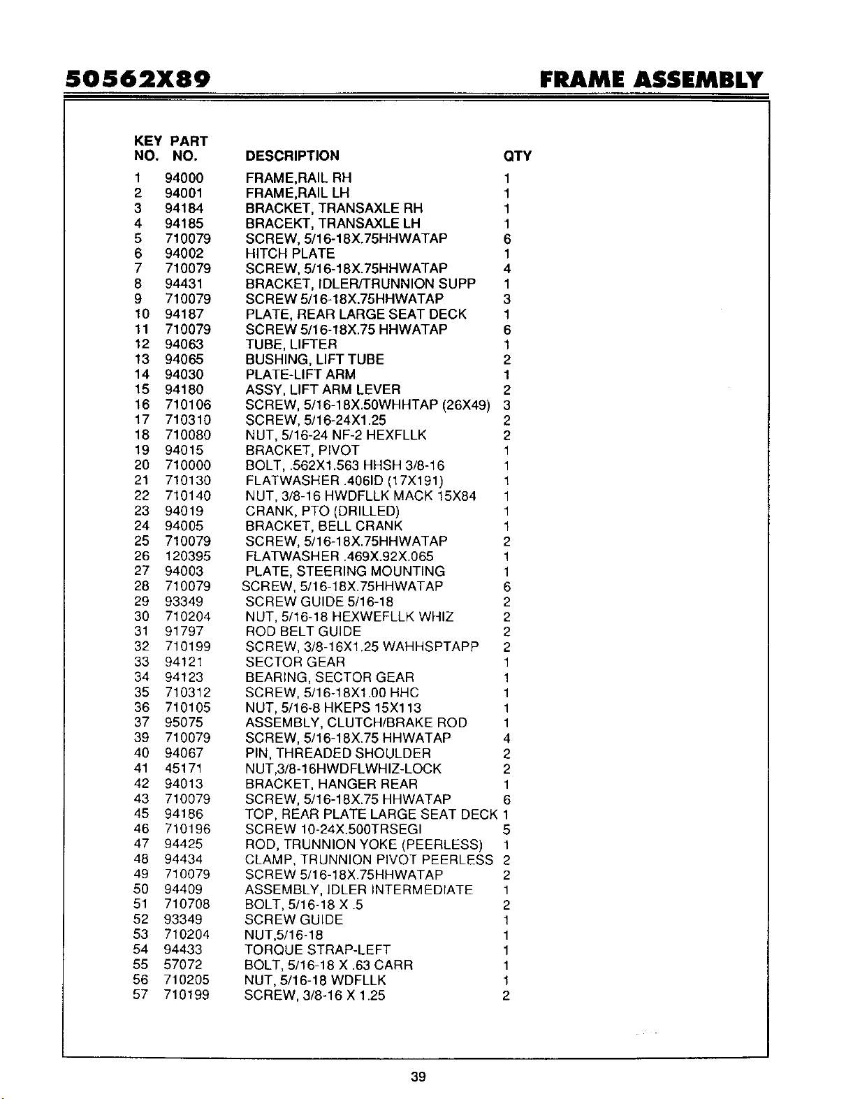
SOS62X89 FRAME ASSEMBLY
KEY PART
NO. NO.
1 94000
2 94001
3 94184
4 94185
5 710079
6 94002
7 710079
8 94431
9 710079
10 94187
11 710079
12 94063
13 94065
14 94030
15 94180
16 710106
17 710310
18 710080
19 94015
20 710000
21 710130
22 710140
23 94019
24 94005
25 710079
26 120395
27 94003
28 710079
29 93349
30 710204
31 91797
32 710199
33 94121
34 94123
35 710312
36 710105
37 95075
39 710079
40 94067
41 45171
42 94013
43 710079
45 94186
46 710196
47 94425
48 94434
49 710079
50 94409
51 710708
52 93349
53 710204
54 94433
55 57072
56 710205
57 710199
DESCRIPTION QTY
FRAME,RAIL RH 1
FRAME,RAIL LH 1
BRACKET, TRANSAXLE RH 1
BRACEKT, TRANSAXLE LH 1
SCREW, 5/16-18X.75HHWATAP 6
HITCH PLATE 1
SCREW, 5/16-18X.75HHWATAP 4
BRACKET, IDLER/TRUNNION SUPP 1
SCREW 5/16-18X.75HHWATAP 3
PLATE, REAR LARGE SEAT DECK 1
SCREW 5/16-18X.75 HHWATAP 6
TUBE, LIFTER 1
BUSHING, LIFT TUBE 2
PLATE-LIFT ARM 1
ASSY, LIFT ARM LEVER 2
SCREW, 5/16-18X.50WHHTAP (26X49) 3
SCREW, 5/16-24Xl.25 2
NUT, 5/16-24 NF-2 HEXFLLK 2
BRACKET, PIVOT 1
BOLT, .562X1.563 HHSH 3/8-16 1
FLATWASHER .4061D (17X191 ) 1
NUT, 3/8-16 HWDFLLK MACK 15X84 1
CRANK, PTO (DRILLED) 1
BRACKET, BELL CRANK 1
SCR EW, 5/16-18X.75HHWATAP 2
FLATWASH ER .469X.92X.065 1
PLATE, STEERING MOUNTING 1
SCR EW, 5/16-18X.75HHWATAP 6
SCREW GUIDE 5/16-18 2
NUT, 5/16-18 HEXWEFLLK WHIZ 2
ROD BELT GUIDE 2
SCREW, 3/8-16X1.25 WAHHSPTAPP 2
SECTOR GEAR 1
BEARING, SECTOR GEAR 1
SCREW, 5/16-18X1.00 HHC 1
NUT, 5/16-8 HKEPS 15X113 1
ASSEMBLY, CLUTCH/BRAKE ROD 1
SCREW, 5/16-18X.75 HHWATAP 4
PIN, THREADED SHOULDER 2
NUT,3/8-16HWDFLWHIZ-LOCK 2
BRACKET, HANGER REAR 1
SCREW, 5/16-18X.75 HHWATAP 6
TOP, REAR PLATE LARGE SEAT DECK 1
SCREW 10-24X.500TRSEGI 5
ROD, TRUNNION YOKE (PEERLESS) 1
CLAMP, TRUNNION PIVOT PEERLESS 2
SCR EW 5/16-18X.75HHWATAP 2
ASSEMBLY, IDLER INTERMEDIATE 1
BOLT, 5/16-18 X .5 2
SCREW GUIDE 1
NUT,5/16-18 1
TORQUE STRAP-LEFT 1
BOLT, 5/16-18 X .63 CARR 1
NUT, 5/16-18 WDFLLK 1
SCREW, 3/8-16 X 1.25 2
39
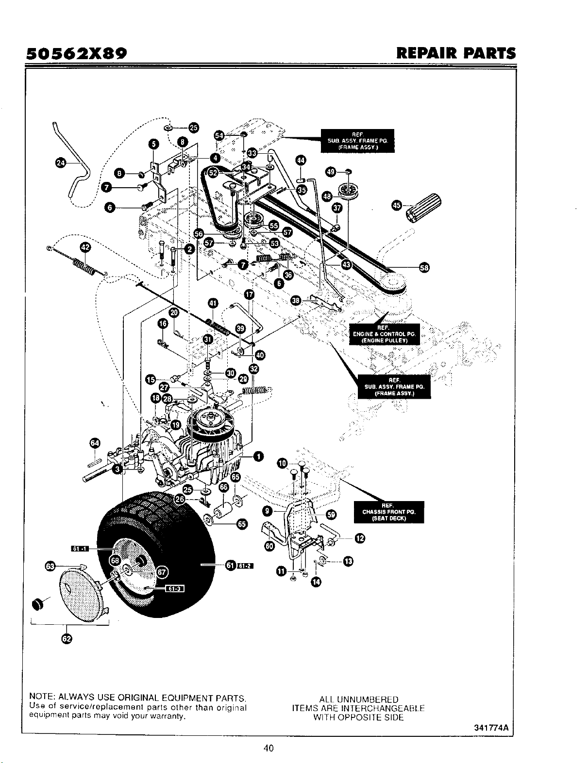
SOS62X89 REPAIR PARTS
Q
NOTE: ALWAYS USE ORIGINAL EQUIPMENT PARTS,
Use of service/replacement parts other than original
equipment parts may void your warranty.
ALL UNNUMBERED
ITEMS ARE INTERCHANGEABLE
WITH OPPOSITE SIDE
341774A
40
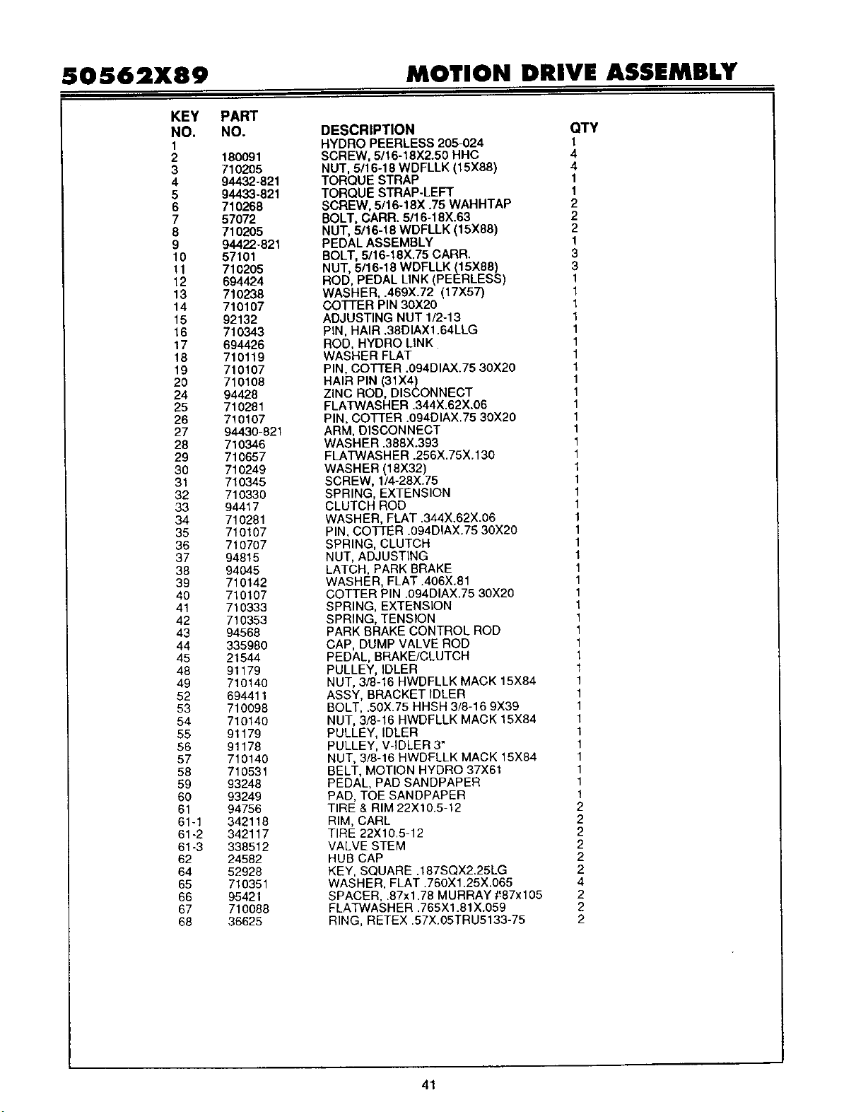
50S62X89 MOTION DRIVE ASSEMBLY
KEY
NO.
1
2
3
4
5
6
7
8
9
1o
11
12
13
14
15
16
17
18
19
20
24
25
25
27
28
29
30
31
32
33
34
35
36
37
38
39
40
41
42
43
44
45
48
49
52
53
54
55
56
57
58
59
60
61
61-1
61-2
61-3
62
64
65
66
67
68
PART
NO.
180091
710205
94432-821
94433-821
710268
57072
710205
94422-821
57101
710205
694424
710238
710107
92132
71O343
694426
710119
710107
710108
94428
710281
710107
94430-821
710346
710657
710249
710345
710330
94417
710281
710107
710707
94815
94045
710142
710107
710333
710353
94568
335980
21544
91179
710140
694411
710098
710140
91179
91178
710140
710531
93248
93249
94756
342118
342117
338512
24582
52928
710351
95421
710088
36625
DESCRIPTION QTY
HYDRO PEERLESS 205-024 1
SCREW, 5/16-18X2.50 HHC 4
NUT, 5/16-18 WDFLLK (15X88) 4
TORQUE STRAP 1
TORQUE STRAP-LEFT 1
SCREW, 5/16-18X .75 WAHHI'AP 2
BOLT, CARR. 5/16-18X.63 2
NUT, 5/16-18 WDFLLK (15X88) 2
PEDAL ASSEMBLY 1
BOLT, 5/16-18X.75 CARR. 3
NUT, 5/16-18 WDFLLK (15X88) 3
ROD, PEDAL LINK (PEERLESS) 1
WASHER, .469X.72 (17X57) 1
COTTER PIN 30X20 1
ADJUSTING NUT 1/2-13 1
PIN, HAIR .38DIAX1.64LLG 1
ROD, HYDRO LINK 1
WASHER FLAT 1
PIN, COTTER .094DIAX.75 30X20 1
HAIR PIN (31X4) 1
ZINC ROD, DISCONNECT 1
FLATWASHER .344×.62X.06 1
PIN, COFFER .094DIAX.75 30X20 1
ARM, DISCONNECT 1
WASHER .388X.393 1
FLATWASHER .256X.75X.136 1
WASHER (18X32) 1
SCREW, 1/4-28X.75 1
SPRING, EXTENSION 1
CLUTCH ROD 1
WASHER, FLAT .344X.62X.06 1
PIN, COTFER .094DIAX.75 30X20 1
SPRING, CLUTCH 1
NUT, ADJUSTING 1
LATCH, PARK BRAKE 1
WASHER, FLAT .408X.81 1
COTTER PIN .094DIAX.75 30X20 1
SPRING, EXTENSION 1
SPRING, TENSION 1
PARK BRAKE CONTROL ROD 1
CAP, DUMP VALVE ROD 1
PEDAL, BRAKE/CLUTCH 1
PULLEY, IDLER 1
NUT, 3/8-16 HWDFLLK MACK 15X84 !
ASSY, BRACKET IDLER 1
BOLT, .50X.75 HHSH 3/8-16 9X39 1
NUT, 3/8-16 HWDFLLK MACK 15X84 1
PULLEY, IDLER 1
PULLEY, V-IDLER 3" 1
NUT, 3/8-16 HWDFLLK MACK 15X84 1
BELT, MOTION HYDRO 37X61 1
PEDAL, PAD SANDPAPER 1
PAD, TOE SANDPAPER 1
TIRE & RIM 22X10.5-12 2
RIM, CARL 2
TiRE 22X10.5-12 2
VALVE STEM 2
HUB CAP 2
KEY, SQUARE .187SQX2.25LG 2
WASHER, FLAT .760X l.25X.065 4
SPACER, .87x1.78 MURRAY 1!87x105 2
FLATWASHER .765X1.81X.059 2
RING, RETEX .57X.05TRU5133-75 2
41
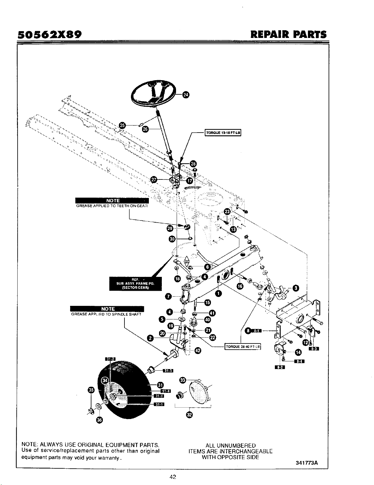
SOS62X89 REPAIR PARTS
1
GREASE APPLtED TO SPINDLE SHAFT
-@
[TOROUE 25-40 FT- LB]
L
NOTE: ALWAYS USE ORIGINAL EQUIPMENT PARTS.
Use of service/replacement parts other than original
equipment parts may void your warranty.
ALL UNNUMBERED
ITEMS ARE INTERCHANGEABLE
WITH OPPOSITE SIDE
341773A
42
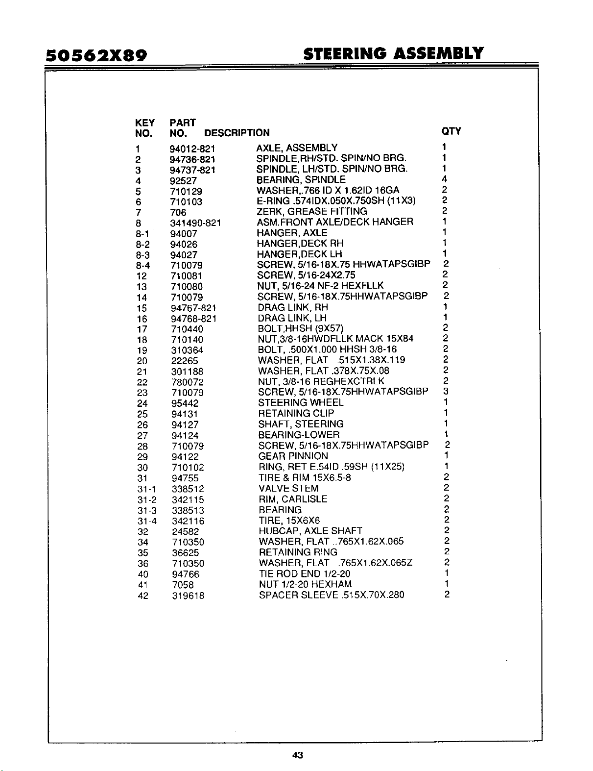
SO $62X89 STEERING ASSEMBLY
KEY PART
NO. NO. DESCRIPTION
1 94012-821
2 94736-821
3 94737-821
4 92527
5 710129
6 710103
7 706
8 341490-821
8-1 94007
8-2 94026
8-3 94027
8-4 710079
12 710081
13 710080
14 710079
15 94767-821
16 94768-821
17 710440
18 710140
19 310364
20 22265
21 301188
22 780072
23 710079
24 95442
25 94131
26 94127
27 94124
28 710079
29 94122
30 710102
31 94755
31-1 338512
31-2 342115
31-3 338513
31-4 342116
32 24582
34 710350
35 36625
36 710350
40 94766
41 7058
42 319618
OTY
AXLE, ASSEMBLY 1
SPINDLE,RH/STD. SPIN/NO BRG. 1
SPINDLE, LH/STD. SPIN/NO BRG. 1
BEARING, SPINDLE 4
WASHER,.766 ID X 1.621D 16GA 2
E-RING .5741DX.050X.750SH (11X3) 2
ZERK, GREASE FITTING 2
ASM.FRONT AXLE/DECK HANGER 1
HANGER, AXLE 1
HANGER,DECK RH 1
HANGER,DECK LH 1
SCREW, 5/16-18X.75 HHWATAPSGIBP 2
SCREW, 5/16-24X2.75 2
NUT, 5/16-24 NF-2 HEXFLLK 2
SCREW, 5/16-18X.75HHWATAPSGIBP 2
DRAG LINK, RH 1
DRAG LINK, LH 1
BOLT,HHSH (9X57) 2
NUT,3/8-16HWDFLLK MACK 15X84 2
BOLT, _500X1.000 HHSH 3/8-16 2
WASHER, FLAT .515X1.38X.119 2
WASHER, FLAT .378X.75X.08 2
NUT, 3/8-16 REGHEXCTRLK 2
SCREW, 5/16-18X.75HHWATAPSGIBP 3
STEERING WHEEL 1
RETAINING CLIP 1
SHAFT, STEERING 1
BEARING-LOWER 1
SCREW, 5/16-18X.75HHWATAPSGIBP 2
GEAR PINNION 1
RING, RET E.541D .59SH (11X25) 1
TIRE & RIM 15X6.5-8 2
VALVE STEM 2
RIM, CARLISLE 2
BEARING 2
TIRE, 15X6X6 2
HUBCAP, AXLE SHAFT 2
WASHER, FLAT ..765X1.62X.065 2
RETAINING RING 2
WASHER, FLAT .765X1.62X.065Z 2
TIE ROD END 1/2-20 1
NUT 1/2-20 HEXHAM 1
SPACER SLEEVE .515X.70X.280 2
43
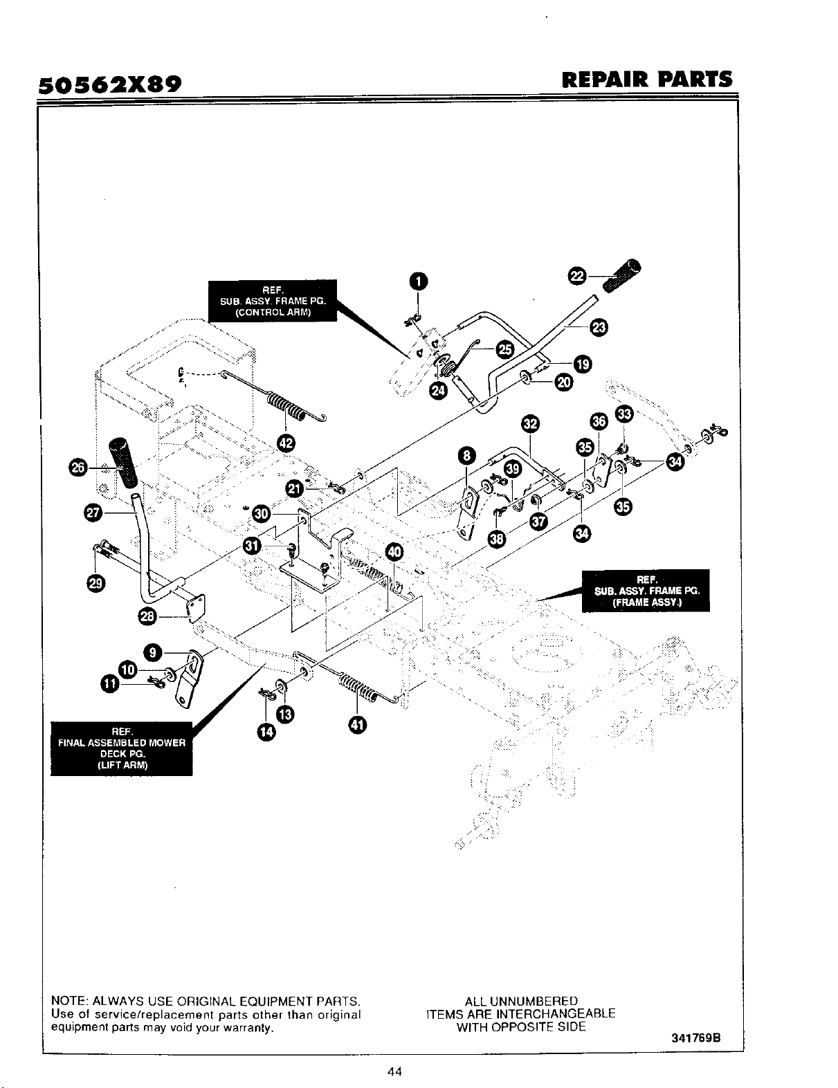
SOS62X89 REPAIR PARTS
0
@
0
NOTE: ALWAYS USE ORIGINAL EQUIPMENT PARTS•
Use of service/replacement parts other than original
equipment parts may void your warranty.
ALL UNNUMBERED
ITEMS ARE INTERCHANGEABLE
WITH OPPOSITE SIDE
34176gB
44
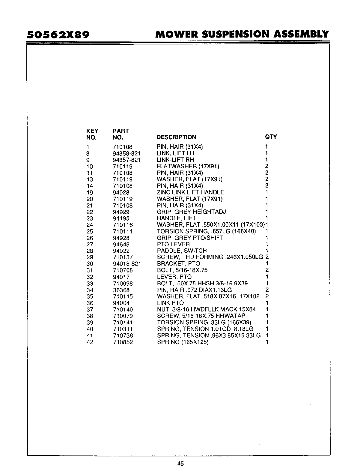
50562X89 MOWER SUSPEHSION ASSEMBLY
KEY
NO.
1
8
9
10
11
13
14
19
20
21
22
23
24
25
26
27
28
29
30
31
32
33
34
35
36
37
38
39
4O
41
42
PART
NO.
710108
94858-821
94857-821
710119
710108
710119
710108
94028
710119
710108
94929
94195
710116
710111
94928
94648
94022
710137
94018-821
710708
94017
710098
36368
710115
94004
710140
710079
710141
710311
710736
710852
DESCRIPTION QTY
PIN, HAIR (31X4)
LINK, LIFT LH
LINK-LIFT RH
FLATWASHER (17X91)
PIN, HAIR (31X4)
WASHER, FLAT (17X91)
PIN, HAIR (31X4)
ZINC LINK LIFT HANDLE
WASH ER, FLAT (17X91)
PIN, HAIR (31X4)
GRIP, GREY HEIGHTADJ.
HANDLE, LIFT
1
1
1
2
2
2
2
1
1
1
1
1
WASHER, FLAT .550X1.00X11 (17X103)1
TORSION SPRING, .657LG (166X40) 1
GRIP, GREY PTO/SHIFT 1
PTO LEVER 1
PADDLE, SWITCH 1
SCREW, THD FORMING .246X1.050LG 2
BRACKET, PTO 1
BOLT, 5/16-18X.75 2
LEVER, PTO 1
BOLT, .50X.75 HHSH 3/8-16 9X39 1
PIN, HAIR .072 DIAX1.13LG 2
WASHER, FLAT .518X.87X16 17X102 2
LINK PTO 1
NUT, 3/8-16 HWDFLLK MACK 15X84 1
SCREW, 5/16-18X.75 HHWATAP 1
TORSION SPRING .33LG (166X39) 1
SPRING, TENSION 1.01OD 8.18LG 1
SPRING, TENSION .96X3.85X15.33LG 1
SPRING (165X125) 1
45
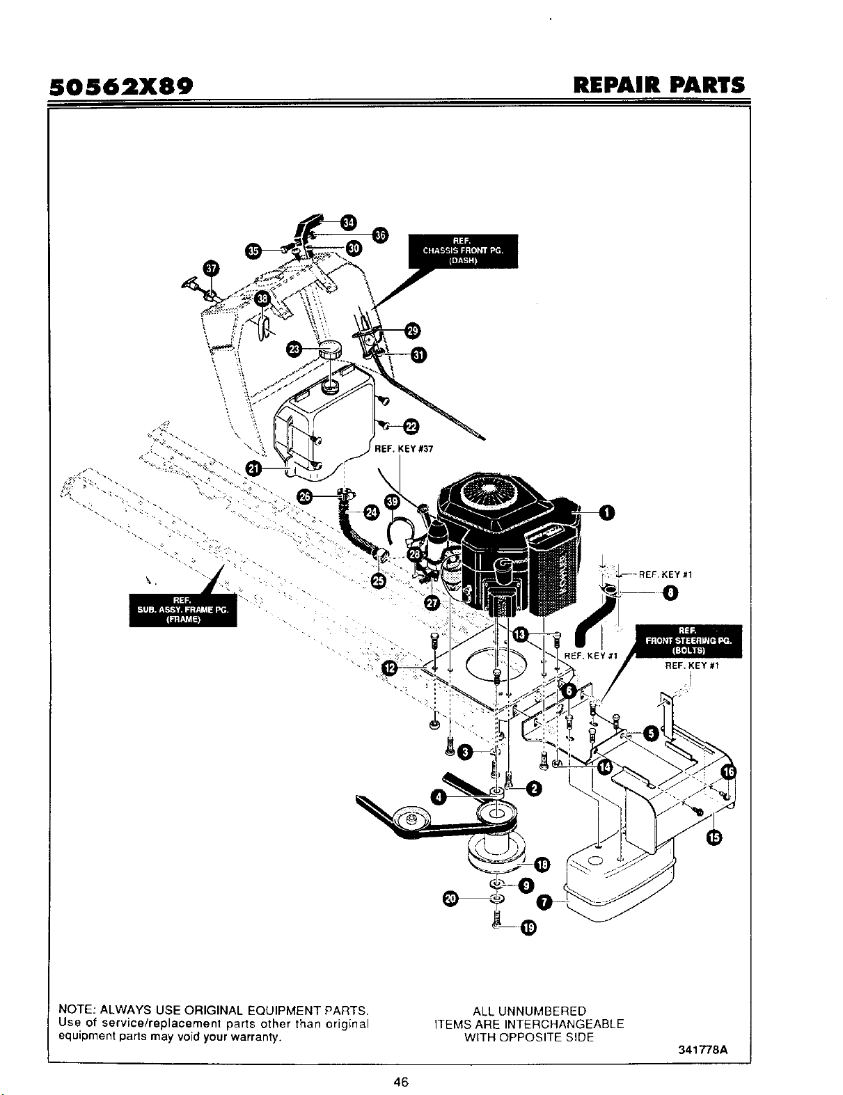
50562X89 REPAIR PARTS
\
tEF. KEY #37
REF. KEY #1
NOTE: ALWAYS USE ORIGINAL EQUIPMENT PARTS.
Use of service/replacement parts other than original
equipment parts may void your warranty.
ALL UNNUMBERED
ITEMS ARE INTERCHANGEABLE
WITH OPPOSITE SIDE
341778A
46
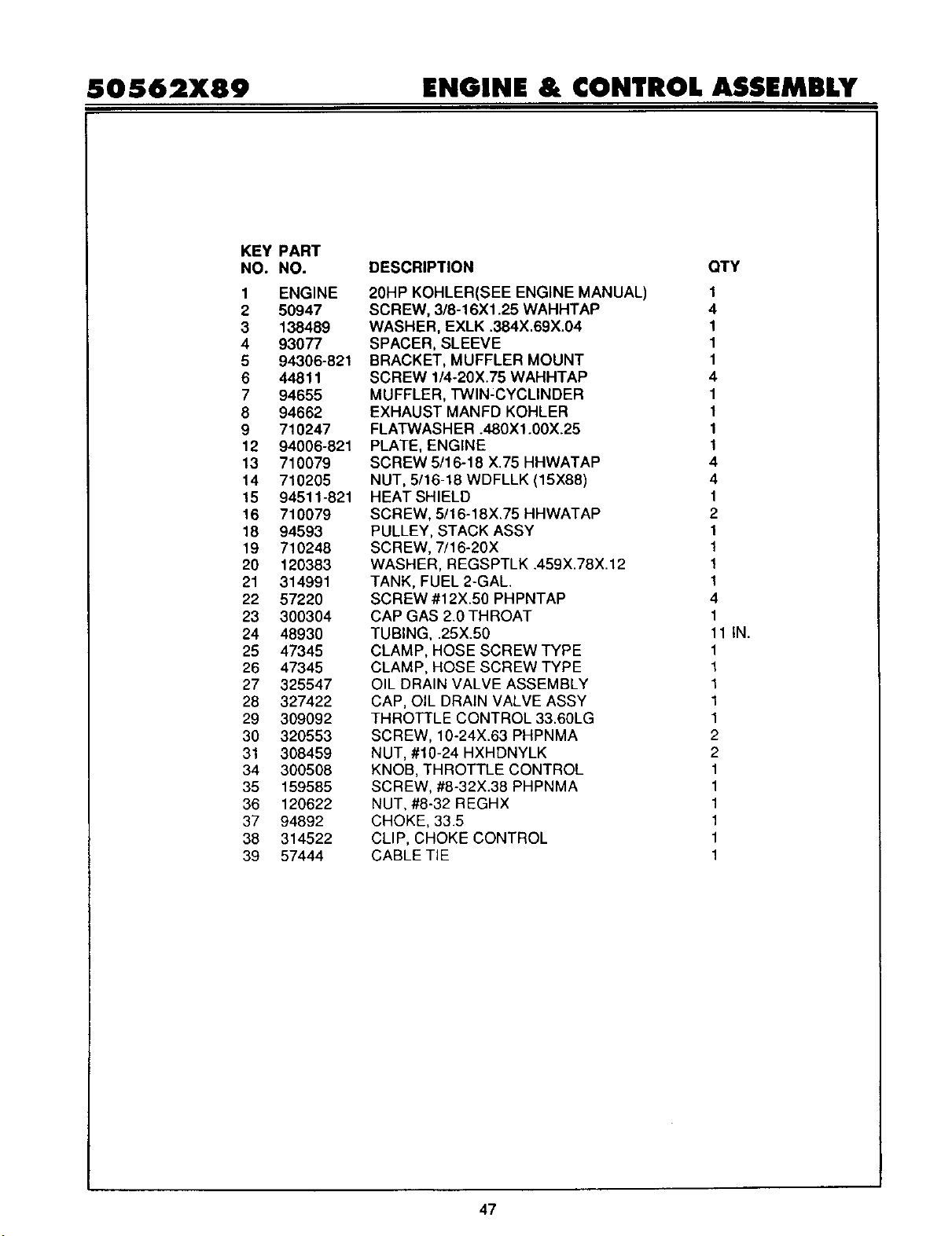
50562X89 ENGINE & CONTROL ASSEMBLY
KEY
NO.
1
2
3
4
5
6
7
8
9
12
13
14
15
16
18
19
20
21
22
23
24
25
26
27
28
29
30
31
34
35
36
37
38
39
PART
NO.
ENGINE
50947
138489
93077
94306-821
44811
94655
94662
710247
94006-821
710079
710205
94511-821
710079
94593
710248
120383
314991
57220
300304
48930
47345
47345
325547
327422
309092
320553
308459
300508
159585
120622
94892
314522
57444
DESCRIPTION CITY
20HP KOHLER(SEE ENGINE MANUAL) 1
SCREW, 3/8-16X1.25 WAHHTAP 4
WASHER, EXLK .384X.69X.04 1
SPACER, SLEEVE 1
BRACKET, MUFFLER MOUNT 1
SCREW 1/4-20X.75 WAHHTAP 4
MUFFLER, TWlN:CYCLINDER 1
EXHAUST MANFD KOHLER 1
FLATWASHER .480X1.00X.25 1
PLATE, ENGINE 1
SCREW 5/16-18 X.75 HHWATAP 4
NUT, 5/16-18 WDFLLK (15X88) 4
HEAT SHIELD 1
SCREW, 5/16-18X.75 HHWATAP 2
PULLEY, STACK ASSY 1
SCREW, 7/16-20X 1
WASHER, REGSPTLK .459X.78X.12 1
TANK, FUEL 2-GAL. 1
SCREW #12X.50 PHPNTAP 4
CAP GAS 2.0 THROAT 1
TUBING, .25X.50 11 IN.
CLAMP, HOSE SCREW TYPE 1
CLAMP, HOSE SCREW TYPE 1
OIL DRAIN VALVE ASSEMBLY 1
CAP, OIL DRAIN VALVE ASSY 1
THROTTLE CONTROL 33.60LG 1
SCREW, 10-24X.63 PHPNMA 2
NUT, #10-24 HXHDNYLK 2
KNOB, THROTTLE CONTROL 1
SCREW, #8-32X.38 PHPNMA 1
NUT, #8-32 REGHX 1
CHOKE, 33.5 1
CLIP, CHOKE CONTROL 1
1CABLE TIE
47
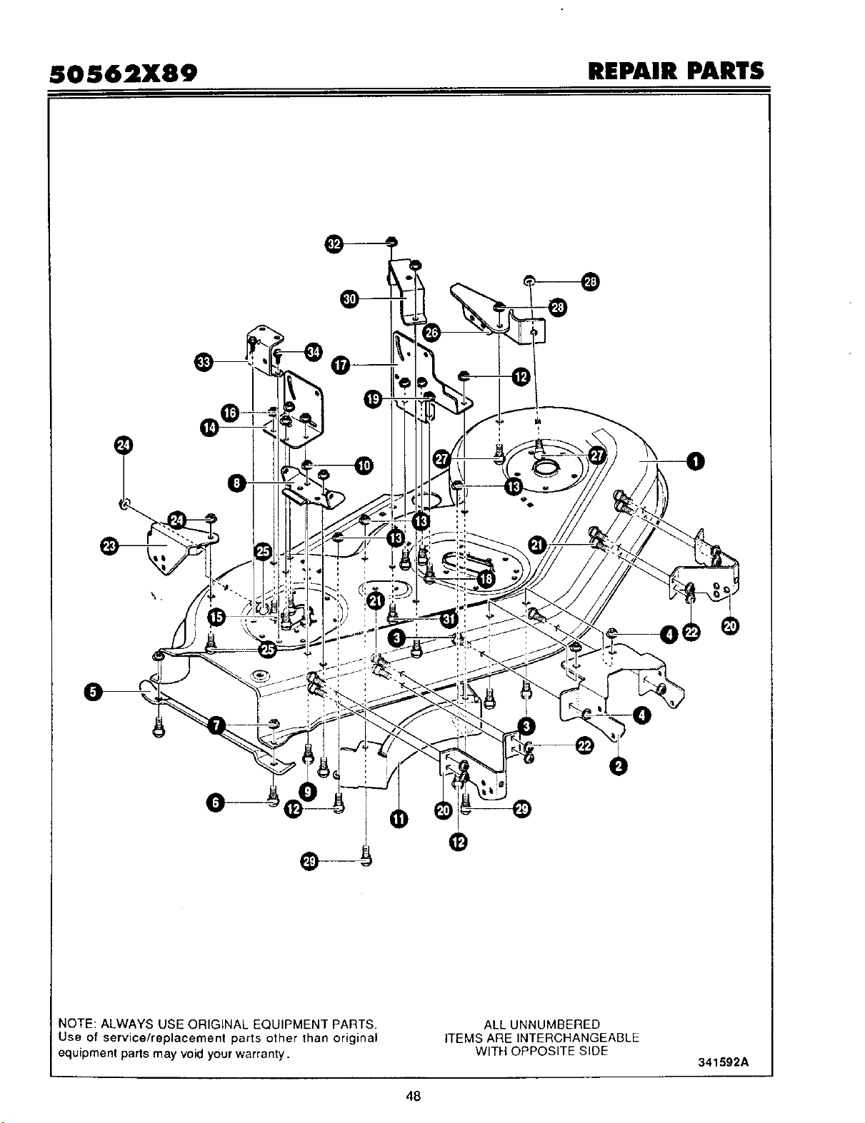
SOS62X89 REPAIR PARTS
0
NOTE: ALWAYS USE ORIGINAL EQUIPMENT PARTS.
Use of service/replacement parts other than original
equipment parts may void your warranty.
ALL UNNUMBERED
ITEMS ARE INTERCHANGEABLE
WITH OPPOSITE SIDE
341592A
48

SOS62X89 PRE-PAINTED DECK ASSEMBLY
KEY
NO.
1
2
3
4
5
6
7
8
9
10
11
12
13
14
15
16
17
18
19
20
21
22
23
24
25
26
27
28
29
3O
31
32
33
34
PART
NO.
94663
94693
57072
710204
94715
57072
710205
92104
57072
710205
94825
57072
710204
94694
57072
710204
94695
57072
710204
94718
57072
710204
94716
57072
710204
94717
57072
710204
710079
94601
57072
710204
92140
710079
DESCRIPTION
HOUSING, BLADE50"
BRACKET,FRONT DECK
BOLT, 5/16-18X.63 CARR.
NUT, 5/16-18 HEXWDFLLK WHIZ
BRACKET, CHUTE SUPPORT
BOLT, 5/16-18X.63 CARR.
NUT 5/16-18 WDFLLK (15X88)
HINGE, CHUTE BRACKET
BOLT 5/16-18X.63 CARR.
NUT, 5/16-18 WDFLLK (15X88)
BAFFLE, CENTER 50"
BOLT, 5/16-18X.63 CARR.
NUT, 5/16-18 HEXWDFLLK WHIZ
BRACKET, LIFTER RH
BOLT, 5/16-18X.63 CARR.
NUT 5/16-18 HEXWDFLLK WHIZ
BRACKET, LIFTER LH
BOLT, 5/16-18X.63 CARR.
NUT, 5/16-18 HEXWDFLLK WHIZ
BRACKET, GAUGE WHEEL FRONT
BOLT, 5/16-18X.63 CARR.
NUT, 5/16-18 HEXWDFLLK WHIZ
BRACKET, GAUGE WHEEL RH
BOLT, CARR. 5/16-18X.63
NUT, 5/16-18 HEXWDFLLK WHIZ
BRACKET, GAUGE WHEEL LH
BOLT, 5/16-18X.63 CARR.
NUT, 5/16-18 HEXWDFLLK
SCREW, 5/16-18X.75 HHWATAP
BRACKET, BELL CRANK
BOLT, 5/16-18X.63 CARR.
NUT, 5/16-18 HEXWDFLLK
BRACKET, PULLEY COVER
SCREW, 5/16-18X.75 HHWATAP
QTY
1
1
4
4
1
2
2
1
2
2
1
4
4
1
4
4
1
4
4
2
8
8
1
2
2
1
2
2
2
1
2
2
1
2
49
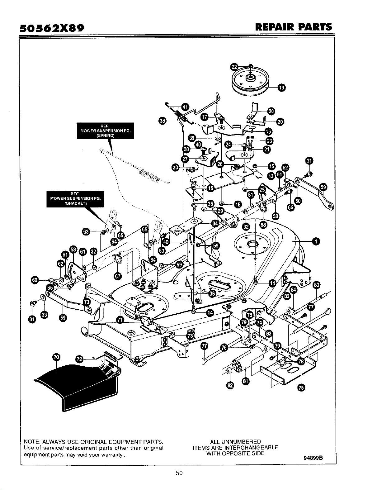
SOS62X89 REPAIR PARTS
IO
NOTE: ALWAYS USE ORIGINAL EQUIPMENT PARTS.
Use of service/replacement parts other than original
equipment parts may void your warranty.
ALL UNNUMBERED
ITEMS ARE INTERCHANGEABLE
WITH OPPOSITE SIDE
94899B
5O
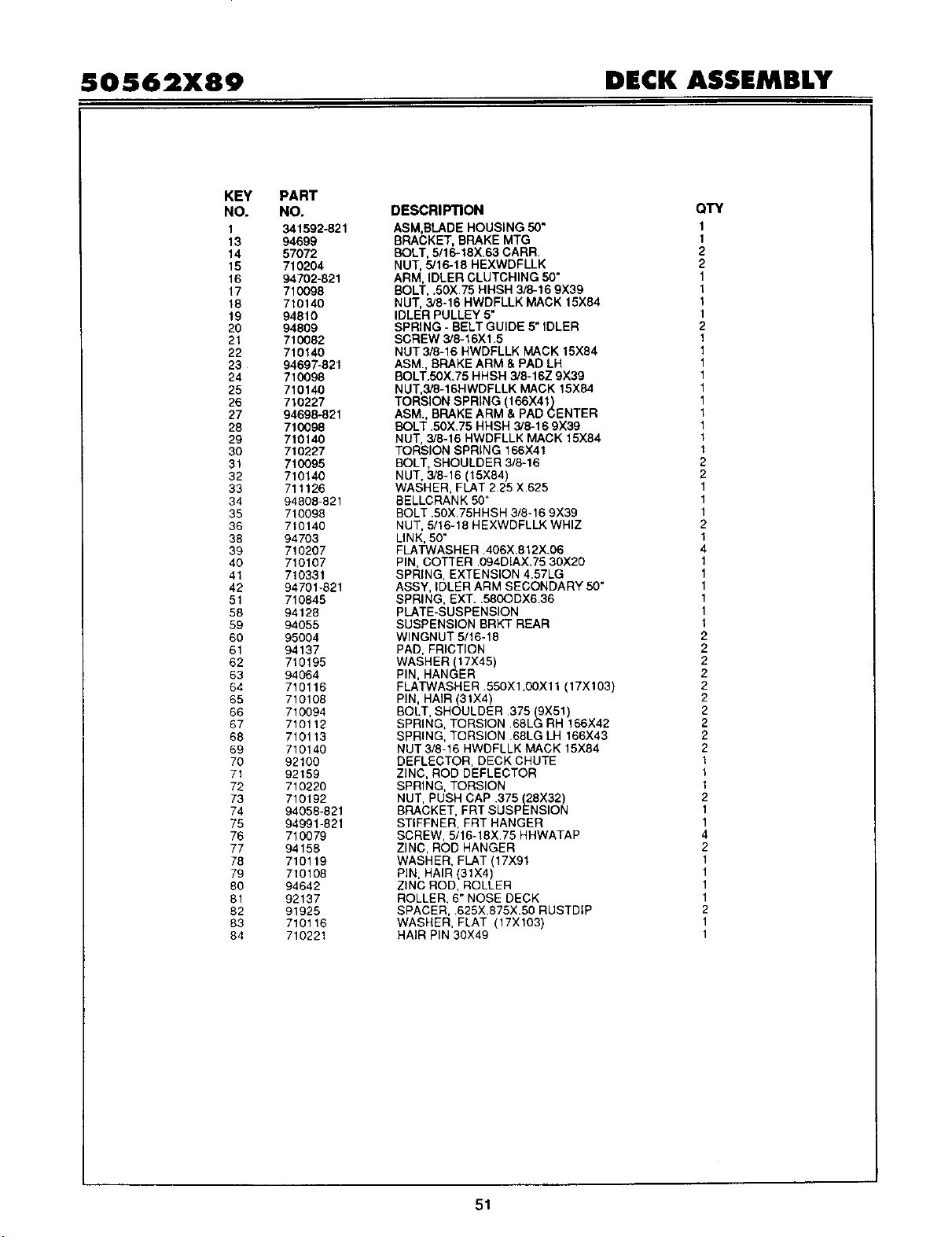
SOS62X89 DECK ASSEMBLY
KEY
NO.
1
13
14
15
16
17
18
19
20
21
22
23
24
25
26
27
29
29
30
31
32
33
34
35
36
38
39
40
41
42
51
58
59
60
61
62
63
64
65
66
67
68
69
70
71
72
73
74
75
76
77
78
79
8o
81
82
83
84
PART
NO.
341592-821
94699
57072
710204
94702-821
710098
710140
94910
94809
710082
710140
94697-821
710098
710140
710227
94698-821
710098
710140
710227
710095
710140
711126
94809 821
710098
710140
94703
710207
710107
710331
94701-821
71O845
94128
94055
95004
94137
710195
94064
710116
710108
710094
710112
710113
710140
92100
92159
710220
710192
94058-821
94991-821
710079
94159
710119
710108
94642
92137
91925
710116
710221
DESCRIPTION
ASM,BLADE HOUSING 50"
BRACKET, BRAKE MTG
BOLT, 5/16-18X.63 CARR
NUT, 5/16-18 HEXWDFLLK
ARM, IDLER CLUTCHING 50"
BOLT, .50)(.75 HHSH 3/6-16 9X39
NUT, 3/8-16 HWDFLLK MACK 15X94
IDLER PULLEY 5"
SPRING - BELT GUIDE 5" IDLER
SCREW 3/8-16Xl .5
NUT 3/8-16 HWDFLLK MACK 15X94
ASM,, BRAKE ARM & PAD LH
BOLT.50X.75 HHSH 3/6-16Z 9X39
NUT,3/8-16HWDFLLK MACK 15X84
TORSION SPRING (166X41)
ASM., BRAKE ARM & PAD CENTER
BOLT .50X,75 HHSH 3/8-16 9X39
NUT, 3/9-16 HWDFLLK MACK 15X84
TORSION SPRING 166X41
BOLT, SHOULDER 3/8-15
NUT, 3/9-16 (15X84)
WASHER, FLAT 225 X,625
BELLCRANK 50"
BOLT .50X 75HHSH 3/8-16 9X39
NUT. 5/16-18 HEXWDFLLK WHIZ
LINK, 50"
FLATWASHER .406X.812X.06
PIN, COTTER .094DIAX.75 30X20
SPRING, EXTENSION 4.57LG
ASSY, IDLER ARM SECONDARY 50"
SPRING. EXT..580ODX6.36
pLATE-SUSPENSION
SUSPENSION BRKT REAR
WlNGNUT 5/16-18
PAD, FRICTION
WASHER (17X45)
PIN, HANGER
FLATWASHER 55OX1.00X11 (17X103)
PiN, HAIR (31X4)
BOLT, SHOULDER 375 (9X51)
SPRING, TORSION .68LG RH 166X42
SPRING. TORSION .68LG LH 166X43
NUT 3/8-16 HWDFLLK MACK 15X84
DEFLECTOR, DECK CHUTE
ZINC. ROD DEFLECTOR
SPRING. TORSION
NUT, PUSH CAP .375 (28X32)
BRACKET. FRT SUSPENSION
STIFFNER, FRT HANGER
SCREW, 5/16-18X.75 HHWATAP
ZINC, ROD HANGER
WASHER. FLAT (17X91
PIN, HAIR (31X4)
ZINC ROD. ROLLER
ROLLER. 6" NOSE DECK
SPACER, .625X 875X.50 RUSTDIP
WASHER, FLAT (17X103)
HAIR PIN 30X49
QTY
1
1
2
2
1
1
1
1
2
1
1
1
1
1
1
1
1
1
1
2
2
1
1
1
2
1
4
1
1
1
1
1
1
2
2
2
2
2
2
2
2
2
2
1
1
1
2
1
1
4
2
1
1
1
1
2
1
1
51
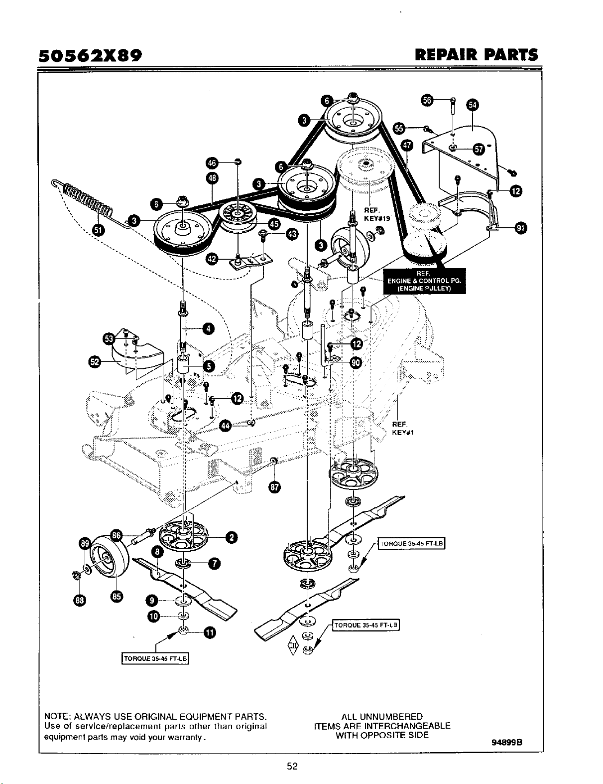
SOS62X89 REPAIR PARTS
.....i ....... !::,_._!i!i
NOTE: ALWAYS USE ORIGINAL EQUIPMENT PARTS.
Use of service/replacement parts other than original
equipment parts may void your warranty.
ALL UNNUMBERED
ITEMS ARE INTERCHANGEABLE
WITH OPPOSITE SIDE
94899 B
52

SOS62X89 DECK ASSEMBLY
KEY
NO.
2
3
4
5
6
7
8
9
10
11
12
43
44
45
46
47
49
52
53
54
55
56
57
85
86
87
88
89
90
91
PART
NO.
92574
94856
94129
94130
710191
92466
94692
710118
710117
710104
710199
710098
710140
91590
710140
710533
710532
94507-821
710134
94645-821
710708
93349
710204
92683
94025
710140
710930
710119
692424
94643-821
DESCRIPTION
JACKSHAFT HOUSING ASSY
PULLEY, JACKSHAFT
JACKSHAFT 7.12LG
SPACER .625X.875Xl.858
NUT, 9!16-18 UNF-2B 15X121
ADAPTER, DECK BLADE
BLADE
WASHERBELLEVILLE 17X166
WASHER, FLAT .625X1.00X.188
NUT, 9/16 REGHEX (15X100)
SCREW, 3/8-16Xl.25 WAHHSPTAPP
BOLT .50X.75HHSH 3/8-16 9X39
NUT 3/8-16 WDFLLK MACK 15X84
PULLEY, IDLER
NUT 3/8-16 WDFLLK MACK 15X84
BELT, PRIMARY 50" DECK 37X93
BELT, SECONDARY 50" 37X92
COVER, PULLEY RH 50" DECK
SCREW, 10-16.190X.62 TRUSS
PULLEY, COVER (TOP) DECK RH
BOLT, 5/16-18X.5 HXFLCA
SCREW GUIDE 5/16-18
NUT, 5/16-18 HEXWDFLLK WHIZ
GAUGE WHEEL 4.94 DIA
BOLT, SPSH 3/8-16X,63 SH 300 LG
NUT, 3/8-16 HWDFLLK 15X84
PIN, CIRCLE 31Xll
WASHER, FLAT (17X91)
ZINC ROD, BELT GUIDE
BRACKET, PULLEY COVER
QTY
1
4
3
3
3
3
3
3
3
3
15
1
1
1
1
I
1
1
2
1
2
1
1
4
4
4
4
4
1
1
53
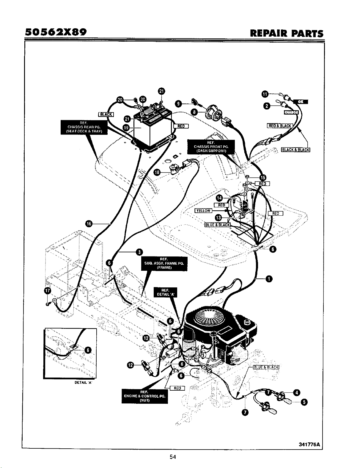
SOS62X89 REPAIR PARTS
• : • ..
D£TAJL 'A'
54
3417"/6A
i
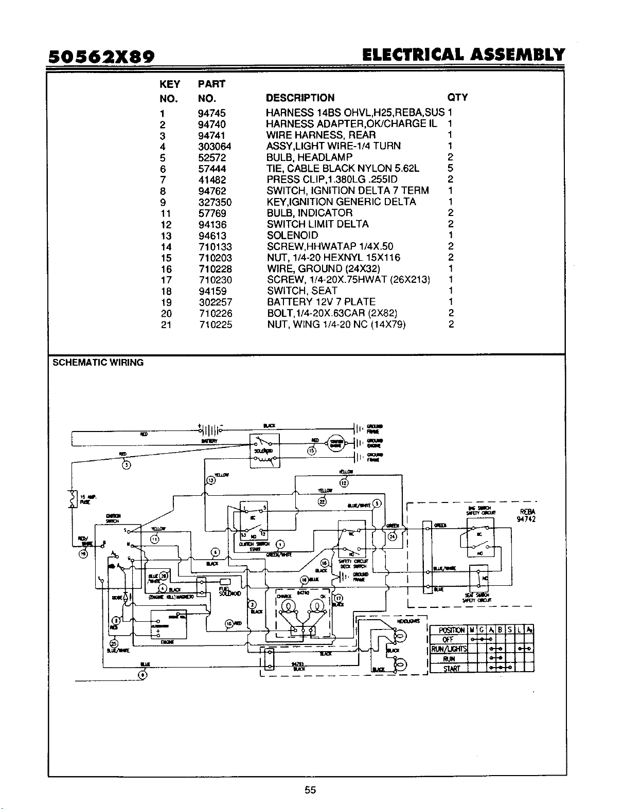
50562X89 ELECTRICAL ASSEMBLY
KEY PART
NO. NO.
1 94745
2 94740
3 94741
4 303064
5 52572
DESCRIPTION
OTY
HARNESS 14BS OHVL,H25,REBA, SUS 1
HARNESS ADAPTER,OK/CHARGE IL 1
WIRE HARNESS, REAR 1
ASSY,LIGHT WIRE-l/4 TURN 1
BULB, HEADLAM P 2
6 57444
7 41482
8 94762
9 327350
11 57769
12 94136
13 94613
14 710133
15 710203
16 710228
17 710230
18 94159
19 302257
20 710226
21 710225
TIE, CABLE BLACK NYLON 5.62L 5
PRESS CLIP,1.380LG .2551D 2
SWITCH, IGNITION DELTA 7 TERM 1
KEY,IGNITION GENERIC DELTA 1
BULB, INDICATOR 2
SWITCH LIMIT DELTA 2
SOLENOID 1
SCREW,HHWATAP 1/4X.50 2
NUT, 1/4-20 HEXNYL 15X116 2
WIRE, GROUND (24X32) 1
SCREW, 1/4-20X.75HWAT (26X213) 1
SWITCH, SEAT 1
BATFERY 12V 7 PLATE 1
BOLT,1/4-20X.63CAR (2X82) 2
NUT, WtNG 1/4-20 NC (14X79) 2
SCHEMATIC WIRING
55
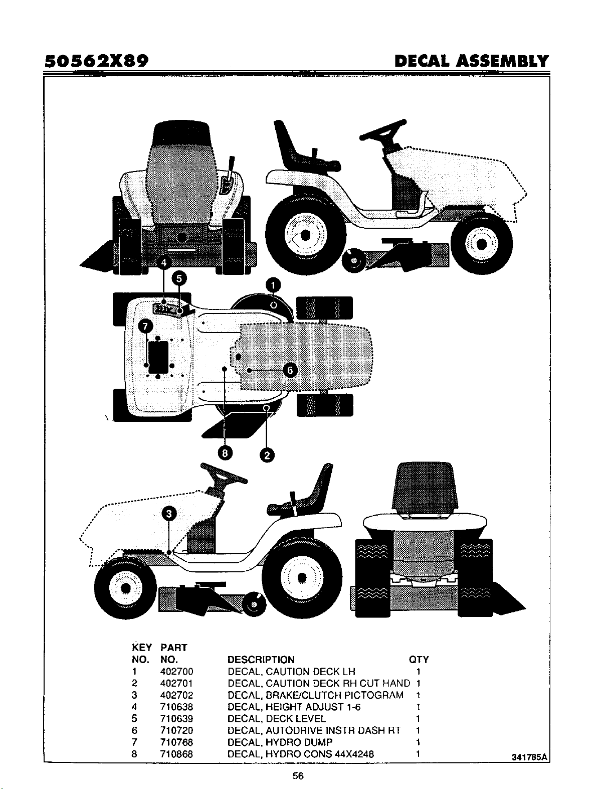
SOS62X89 DECAL ASSEMBLY
.°
/
/
KEY PART
NO. NO.
1 402700
2 402701
3 402702
4 710638
5 710639
6 710720
7 710768
8 710868
DESCRIPTION
DECAL CAUTION DECK LH
DECAL
DECAL
DECAL
DECAL
DECAL
DECAL
DECAL
QTY
1
CAUTION DECK RH CUT HAND 1
BRAKE/CLUTCH PICTOGRAM 1
HEIGHT ADJUST 1-6 1
DECK LEVEL 1
AUTODRIVE INSTR DASH RT 1
HYDRO DUMP 1
HYDRO CONS 44X4248 1
341785A
56
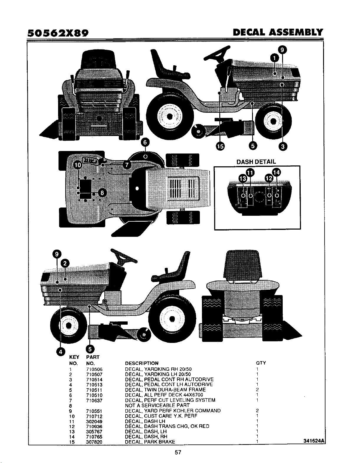
50562X89 DECAL ASSEMBLY
DASH DETAIL
KEY
NO.
1
2
3
4
5
6
7
8
9
10
11
12
13
14
15
PART
NO.
7t0506
710507
710514
710513
710511
710510
710637
710551
710712
302049
710936
305767
710765
307820
DESCRIPTION
DECAL, YARDKING RH 20/50
DECAL, YARDKING LH 20/50
DECAL, PEDAL CONT RH AUTODRIVE
DECAL, PEDAL CONT LH AUTODRIVE
DECAL, TWIN DURA-BEAM FRAME
DECAL, ALL PERF DECK 44X6700
DECAL, PERF CUT LEVELING SYSTEM
NOT A SERVICEABLE PART
DECAL, YARD PERF KOHLER COMMAND
DECAL, CUST CARE Y.K. PERF
DECAL, DASH LH
DECAL, DASH TRANS CHG, OK RED
DECAL, DASH, LH
DECAL, DASH, RH
DECAL, PARK BRAKE
QTY
1
1
1
1
2
1
1
2
1
!
1
1
1
1
57
341624
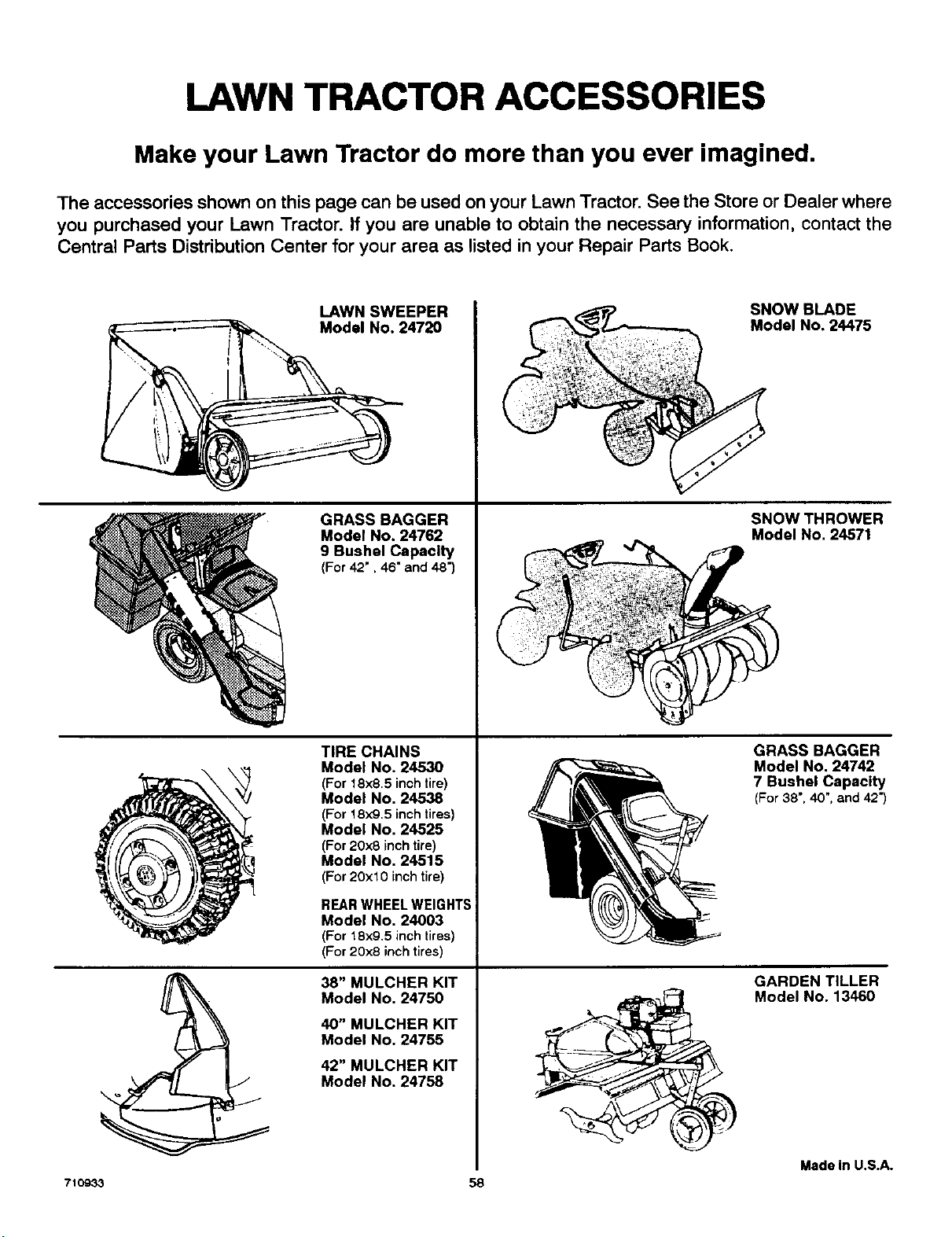
LAWN TRACTOR ACCESSORIES
Make your Lawn Tractor do more than you ever imagined.
The accessories shown on this page can be used on your Lawn Tractor. See the Store or Dealer where
you purchased your Lawn Tractor. If you are unable to obtain the necessary information, contact the
Central Parts Distribution Center for your area as listed in your Repair Parts Book.
71O933
LAWN SWEEPER
Model No. 24720
GRASS BAGGER
Model No. 24762
9 Bushel Capacity
(For42", 46" and48")
TIRE CHAINS
Model No. 24530
(For 18x85 inch tire)
Model No, 24538
(For 18)(9,5 inch tires)
Model No, 24525
(For 20x8 inch tire)
Model No, 24515
(For 20x10 inch tire)
REAR WHEEL WEIGHTS
Model No. 24003
(For 18x9.5 inch tires)
(For 20x8 inch tires)
38" MULCHER KIT
Model No. 24750
40" MULCHER KIT
Model No. 24755
42" MULCHER KIT
Model No. 24758
SNOW BLADE
Model No. 24475
SNOW THROWER
Model No. 24571
58
GRASS BAGGER
Model No. 24742
7 Bushel Capacity
(For38",40",and42")
GARDEN TILLER
Model No. 13460
Madein U.S.A.

NOTES
$9
PARTS DISTRIBUTORS
DEBCO, INC.
2221 2nd. Ave.
South Birmingham, Ala. 35233
(2O5)251-4600
1-800-828-8094
Alabama, Georgia, Florida
BILLIOU'S IHC.
1343 South Main
Porterville, CA 93257
(209) 784-4102
TOLL # 1-800-245-5468
FAX # 1o800-266-7337
Arizona, California, Nevada, Hawafl
BROWN & WISER, INC.
9991 S.W. Avery Street
P.O. Box 1109
Tualatin, OR. 97062
(503) 692-0330
1-800-882-4782
Alaska, Oregon, Washington,
Montana (counties Flathead, Lake,
Lincoln, Mineral, Missoulo, Ravalli,
Sanders), Idaho (counties Ada, Adams,
Benewah, Boise, Bonner, Boundry,
Canyon, Clearwater, Elmore, Gem,
Idaho, Kooten, Latah, Lewis, NEZ Perce,
Owyee, Payette, Shoshone, Valley,
Ravalli, Washington)
\.
CHILTON AIR COOLED ENGINE
319 4th Ave. South
P.O, Box 150806
Nashville, TN. 37215
(615) 254-1634
1-800-621-6934
Tennessee, Arkansas (counties Clay,
Craighead, Crittendan, Cross, Greene,
Jackson, Lawrence, Lee Mississippi,
Monroe, Phillips, Poinsett, Randolph, St.
Francis, Woodruff), Mississippi
(counties Desota, Panola, Tate, Tunica,
Quitman), Missouri (counties Dunkin,
New Madrid, Pemiscot), Virginia
(counties Bland, Buchanan, Dickerson,
Lee, Russell, Scott, Smyth, Tazewell,
Washington, Wise)
FUNK EDWARDS CO.
3653 S. 500 West
P.O. Box 2158
Salt Lake City, UT. 84115
(801) 281-4660
1-800-366-4563
Colorado, Utah, Wyoming, Montana
(all counties except Brown and Wiser),
Idaho (counties Bannock Bearlake,
Bingham, Blaine, Booneville, Butte, Camas,
Caribou; Cassia, Custer, Franklin, Fremont,
Gooding, Jefferson, Jereme, Lemhi,
Lincoln, Madison, Minidoka, Oneida,
Power, Teton, Twin Falls)
GARDNER, INC.
1150 Chesapeake Ave.
Columbus, OH. 43212
(614) 489-7951
1-800-848-8946
Indiana, Kentucky, Michigan (except
Upper Peninsula), Ohio, West Virginia,
Western Pennsylvania with zip codes
up to and including 16999
ENGINES SOUTHWEST
215 Spring St.
P.O. Box 67
Shreveport, LA. 71161-0067
(318) 222-3871
1-800-388-6995
Louisiana, Mississippi (except these
counties: Desota, Panola, Tate, Tunica,
Quitman), Arkansas (except these
counties: Clay, Craighead, Crittendan,
Cross, Greene, Jackson, Lawrence, Lee,
Mississippi, Monroe, Phillips, Poinsett,
Randolph, St. Francis, Woodruff,
Hempstead, Howard, Lafayette, Little
River, Miller, Nevada, Pike, Sevier)
GULF COAST ENGINE, INC.
4202 Russell Dr.
P.O. Box 9724
Corpus Christi, TX 78408
(512) 888-699g
1-800-825-6999
New Mexico, Oklahoma, Texas,
Arkansas (counties Hempstead.
Howard, Lafayette, Little River, Miller,
Nevada, Pike, Sevier)
OSCAR WILSON ENGINE &
PARTS
826 Lone Star Drive
O'Fallon, MO. 63366
(3t4) 978-1313
1-800-873-6722
Illinois (S. ofHwy. 80), Iowa, Ne-
braska, Kansas, Missouri(all counties
except Dunkin, New Madrid, Pemiscot)
CPT CANADA POWER TECHNOL-
OGY LTD.
161 Watline Avenue
Mississauga, Ontario L4Z tP2
Phone: 905-890-6900
1-800 -861-9559
Canada
R.B.I. CORPORATION
P.O. Box 9318
Richmond, VA. 23227
(804) 550-2210
1-800-888-7149
Connecticut, Main, Massachusetts,
New Hamphire, Rhode Island, Ver-
mont, New York, New Jersey, North
and South Carolina, Maryland, Dela-
ware, District of Columbia, Virginia (all
cuonties except Bland, Buchanan,
Dickerson, Lee, Russell, Scott, Smyth,
Tazewell, Washington, Wise),
Pennsylvania, zips 17000 & up
WISCONSIN MAGNETO
4727 N. Teutonia Ave.
P.O. Box 9218
Milwaukee, WI. 55303
(414) 445-2800
1-800-733-7388
Illinois (N. of Hwy. 80) Michigan (Upper
Peninsula), Minnesota, Wisconsin,
North & South Dakota