® U.S. Registered Trademark
Copyright © 2002 Honeywell • •All Rights Reserved
INSTALLATION INSTRUCTIONS/OWNER’S GUIDE
69-1646EF
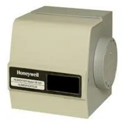
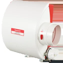
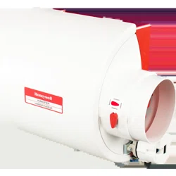
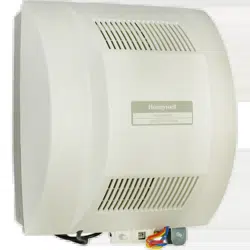
HE360 Humidifier and
Installation Kit
WELCOME
To the comfortable world of humidified air. When you use
your Honeywell humidifier, notice that your skin is not as
dry, and that your scratchy throat and irritated nasal
passages that aggravate allergies and asthma are
steadily improving.
You have also taken the first step in reducing the zapping
you create when you walk on your carpet and then touch
your TV, computer, metal door knob or your pet. Your
furniture and woodwork are also benefitting from the
difference that humidified air makes.
Congratulations! You have just made a great investment
in improving the comfort of your home.
APPLICATION
This kit contains your new Honeywell HE360 Humidifier,
H8908 Humidistat and all the accessories required for
installation.
INSTALLATION
Preparing for the Installation
Be sure to identify all the required (Table 1) accessories
(included) and make sure the appropriate tools are
available before beginning the installation.
Required Accessories (Included)
Required Tools
Tools required for installation include:
• Tin snip.
• Screwdriver.
• Adjustable or open-end wrench.
• Drill, punch or awl.
•Level.
Determining Best Location for Humidifier
CAUTION
Temperature and Static Pressure Hazard.
Can cause property or equipment damage.
Locate humidifier where ambient temperature is
between 32°F (0°C) and 160°F (71°C).
Do not install humidifier where freezing
temperatures could occur.
Be sure supply plenum static pressure is no
greater than 0.4 in. wc and water pressure is no
greater than 124 psi.
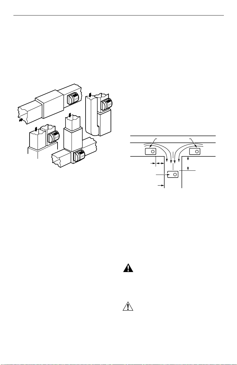
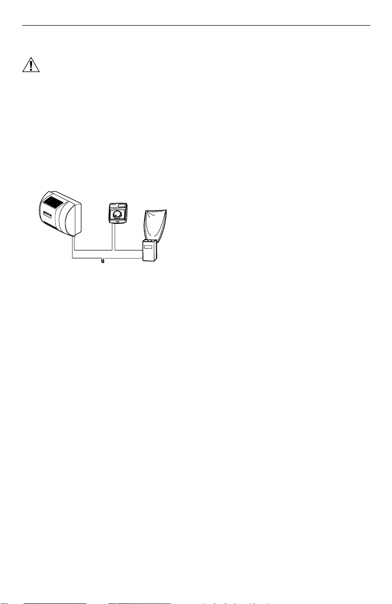
• Select a location for the humidifier on the supply
(warm air stream) plenum. See Fig. 1.
Table 1. Required Accessories.
Quantity Accessory
20 ft (6.2m) 18 gauge, two-strand thermostat wire
20 ft (6.2m) 1/4 in. (6.35 mm) OD feed water tubing
10 ft (3.1m) 1/2 in (12.7 mm) ID drain tubing
1 bag Connecting and mounting hardware:
Wire nuts (4)
No. 8 sheet metal screws (18)
Drain tube clamp
Feed tube mounting clamps (6)
Brass inserts (2)
Plastic compression rings (2)
1 Sail switch
1 H8908 Humidistat
1 bag Saddle Valve Assembly:
Saddle valve and top clamp (1)
Threaded bottom clamp (1)
Bolts (2)
Rubber gasket (1)
Eyelet (1)
Plastic bushing (1)
Table 1. Required Accessories.
Quantity Accessory
To Buy: Visit www.sylvane.com or call (800) 934-9194
Product Support: Contact Honeywell at 1-877-271-8620
HE360 HUMIDIFIER AND INSTALLATION KIT
69-1646EF 2
• Select a location that cannot damage the air
conditioner A-coil during installation.
• Do not locate the humidifier on the furnace body.
• Allow adequate clearance in front of and above the
humidifier so you can easily remove the cover to
perform routine maintenance.
— Mount the humidifier at least 3 in. (78 mm) above
the furnace body to allow adequate space for the
solenoid valve and drain line.
— Mount the humidifier in a conditioned space to
prevent freezing.
Fig. 1. Typical humidifier installation locations.
Selecting Water Supply Location
• Use either hard or soft water in the humidifier and
either hot or cold water. The water flow rate, with the
humidifier running, is 3.5 gal/hr (13 liters/hr) to flush
the pad and provide moisture for evaporation.
• Make sure that the 20 ft (6.2m) of feed water tubing
provided is adequate to connect the water supply
(saddle valve) with the humidifier solenoid valve.
Locating Closest Floor Drain
• Select location with access to a floor drain to provide
drainage for air conditioner condensation and
humidifier drainage.
• If you do not have a drain available, we recommend
that you install the Honeywell Whole House Drum or
Disk Humidifier. Make sure that the 10 ft (3.1m) of
drain tubing is adequate to reach from the humidifier
drain connection to the floor drain.
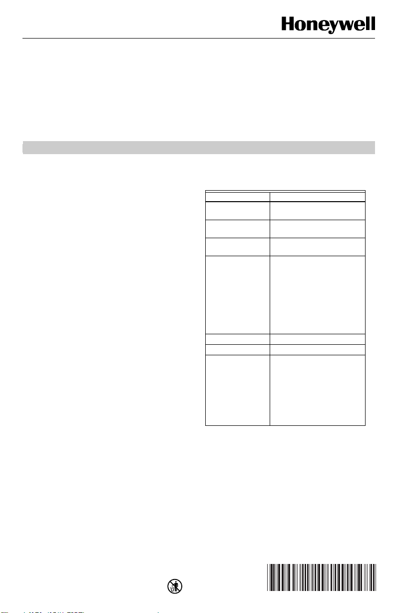
Selecting Location for Sail Switch
• Select a location for the sail switch in the cold air
return duct where the sail is in the direct path of an
unrestricted air stream.
— Sail switch detects when furnace fan is operating.
• Select a location where the air duct is at least 12 in.
(305 mm) deep and 8 in. (203 mm) wide to allow
operation of the sail without affecting the smooth flow
of air in the duct.
— Airflow at the location can be vertical (up or
down) or horizontal.
IMPORTANT
Mounting the S688 in warm air supply duct can
reduce the sail life.
• Mount the switch at least 6 in. (152 mm) upstream
from an elbow or junction, and at least 15 in.
(381 mm) downstream from an elbow or junction.
• Locate the switch on the opposite side of the duct
from the air entrance. (See Fig. 1-3 in S688
Installation Instructions.)
Selecting Location for Humidistat
• Select a location for the humidistat on the return
plenum or on the wall in the living space.
— Mounting on the return plenum is the easiest
installation for the control wiring circuit.
For return duct mounting, the humidistat should be
mounted upstream from the humidifier or bypass so that
it is properly sensing the relative humidity of the living
space. Locate the control at least 8 in. (203 mm)
upstream from the humidifier in the return air duct. (See
Fig 2.)
Fig. 2. Selecting duct location for humidistat.
Locating Closest 120V Electrical Outlet
• Select location with access to an outlet. If not
available, contact an electrician to have one installed.
• Make sure that the humidifier cord is adequate to
reach from the humidifier to the outlet.
• Make sure that the 20 ft (6.2m) of thermostat wire is
adequate to reach from the humidifier solenoid, to the
sail switch, to the humidistat.
Installing the Humidifier
WARNING
Hazardous Voltage
Can cause personal injury or equipment
damage.
Do not cut or drill into any air conditioning or
electrical accessory.
CAUTION
Sharp Edges Installation Hazard.
Can cause personal injury.
Wear gloves and safety glasses.
M12808A
HORIZONTAL
DOWN
FLO
LOWBOY
RETURN
RETURN
RETURN
HIGHBOY
RETURN
ALTERNATE LOCATION
RETURN
AIR
RETURN
AIR
6 in. (152 mm)
MINIMUM
15 in. (381 mm)
MINIMUM
BEST
LOCATION
RETURN AIR DUCT
M12831
HE360 HUMIDIFIER AND INSTALLATION KIT
3 69-1646EF
1. Turn off power to the air handing system at the cir-
cuit breaker.
2. Draw a level line on the plenum in the location
chosen for the humidifier. (Leveling assures opti-
mal humidifier performance.)
3. Locate the template (form number 69-1651
included in the box).
4. Tape the template in position and trace around
the template.
5. Remove the template and carefully cut the rect-
angular opening.
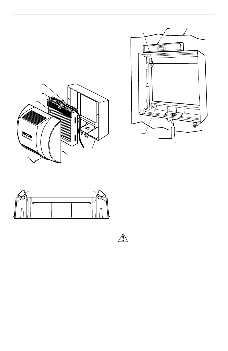
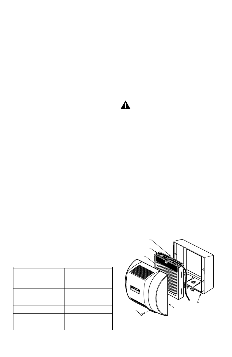
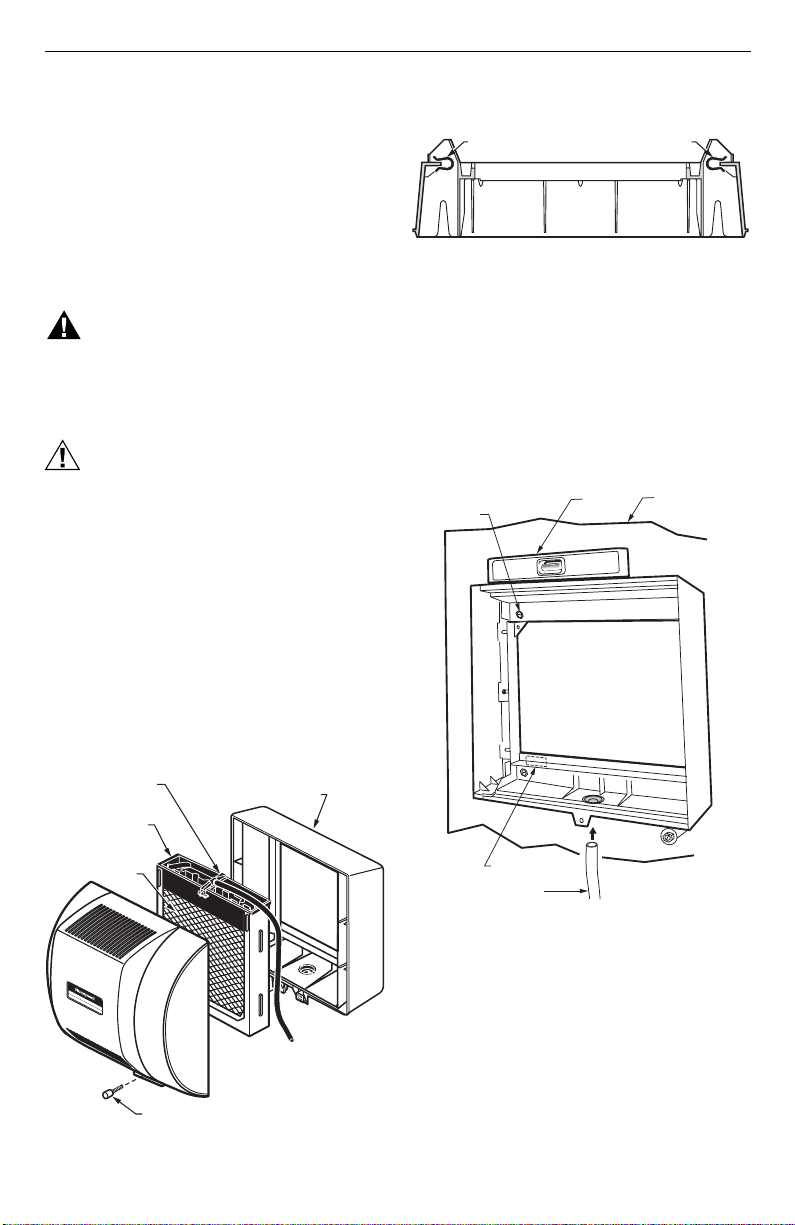
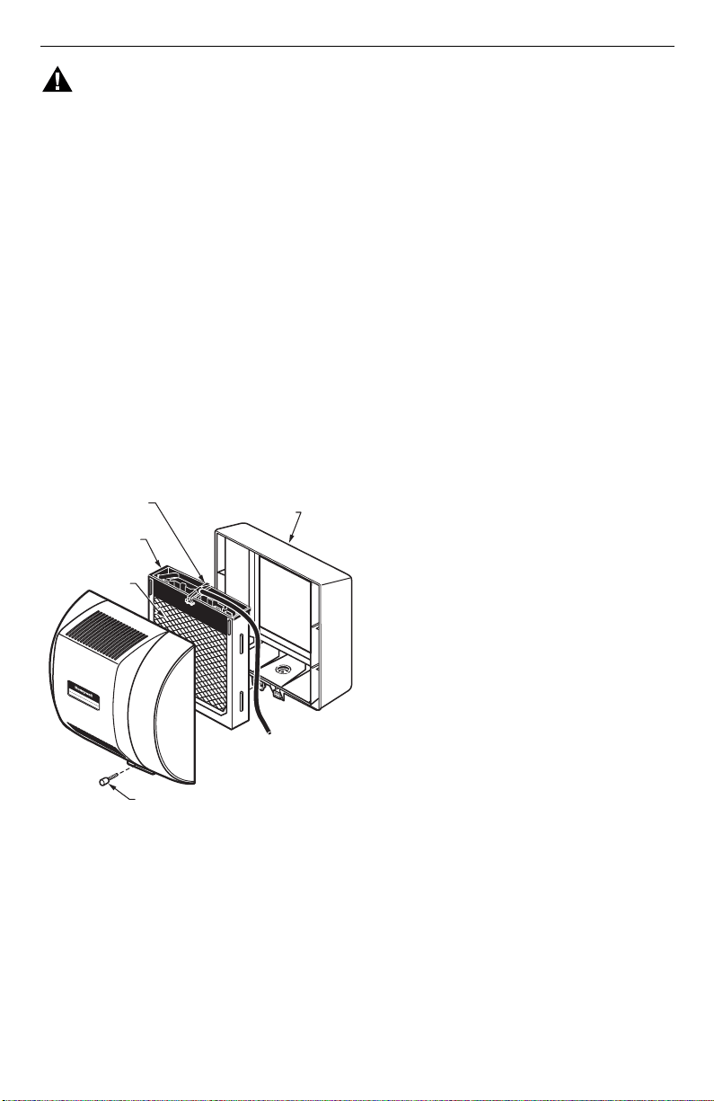
6. Disassemble the humidifier; remove the cover and
take out the humidifier pad assembly. See Fig. 3.
Fig. 3. Disassembling humidifier.
7. Position the securing clips as shown in Fig. 4.
Fig. 4. Position securing clips.
8. Make sure the humidifier housing is level, then
position it in the opening so the plastic tabs are in
place on the lower sheet metal edge of the open-
ing. Use pliers, as necessary, to flatten cut edges.
See Fig. 5.
9. Push in securing clips until completely seated.
10. Drill holes and install the three sheet metal screws
on the top of the humidifier housing. Secure the
housing with the three remaining screws.
Fig. 5. Installing humidifier on duct.
11. Reinstall the humidifier pad assembly in the humid-
ifier housing.
IMPORTANT
Be sure to reconnect the water feed tube and
ensure that the tube is not pinched or kinked.
12. Hinge the cover in place and secure with the
thumbscrew located at the bottom of the cover.
Connecting the Plumbing
Use hot or cold water and either hard or softened water
in the humidifier.
1. Shut off the water.
CAUTION
Chemical Hazard.
Can cause personal injury or equipment
damage.
Do not use any line connected to an air
conditioner.
Do not use gas line.
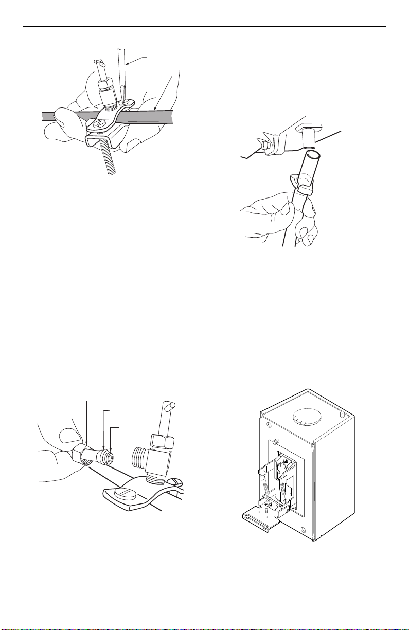
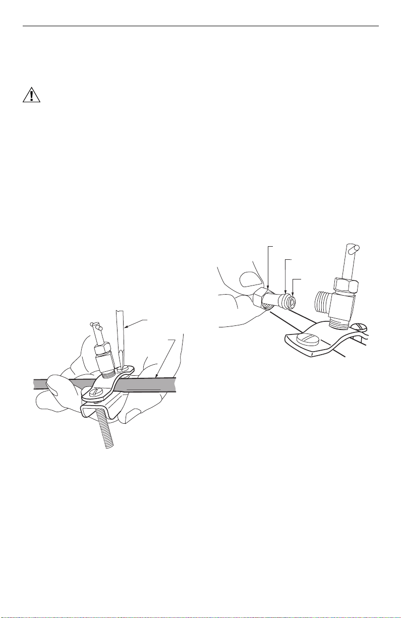
2. Use the self-piercing saddle valve (included) to tap
into the water supply line at the location selected.
See Fig. 6. If tapping into galvanized pipe, drain
line and pre-drill 3/17 in. tap for saddle valve.
NOTE: The saddle valve is not designed to regulate
water flow. The valve is either open or closed.
IMPORTANT
To prevent debris from clogging the solenoid in-
line filter, be sure to install the saddle valve han-
dle pointing toward the ceiling.
M12809
COVER
ASSEMBLY
HUMIDIFIER
PAD ASSEMBLY
FEED TUBE NOZZLE
WATER
DISTRIBUTION TRAY
HUMIDIFIER
HOUSING
THUMB
SCREW
M12813
CLIP
CLIP
DUCT
LEVEL
SHEET METAL
SCREWS (4)
PLASTIC
TABS (2)
DRAIN TUBING
M20204
OPENING
TO AIR DUCT
HE360 HUMIDIFIER AND INSTALLATION KIT
69-1646EF 4
Fig. 6. Installing the saddle valve.
3. Use 1/4 in. (6 mm) OD tubing and connect the sad-
dle valve to the inlet side of the solenoid valveon
the humidifier (see Fig. 7).
a. Place the brass compression nut over the
tubing.
b. Install brass insert into end of tubing.
c. Slide the plastic compression ring over the
tubing. (Discard copper compression ring pro-
vided with valve.)
NOTE: To prevent leaking, use plastic (Delrin) sleeve
rings with plastic tubing. Use copper sleeve
rings only with copper tubing.
d. Insert the tubing into the solenoid valve fitting
and support the valve while tightening the com-
pression nut.
NOTE: Do not over-tighten the compression nut. Mod-
erate tightness prevents leaking.
e. Repeat steps a. through d. for solenoid valve
fitting.
f. Secure tubing with clamps provided.
Fig. 7. Installing feed tubing.
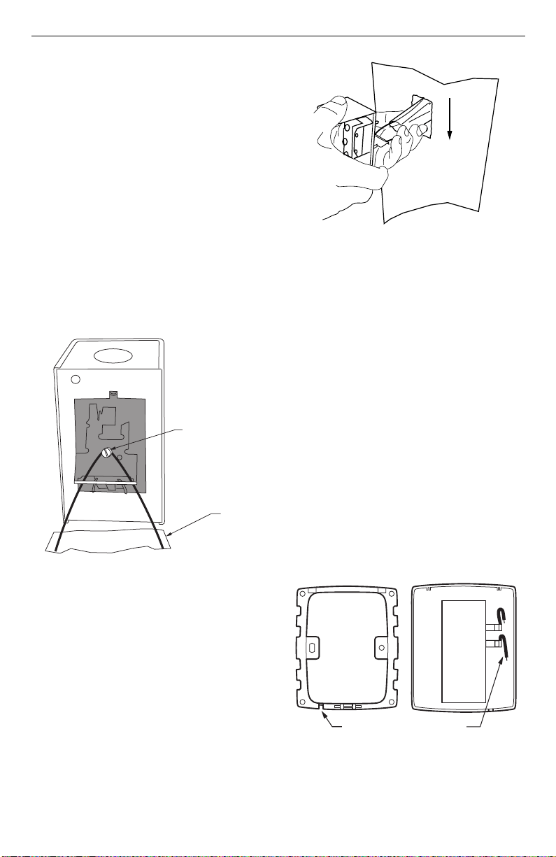
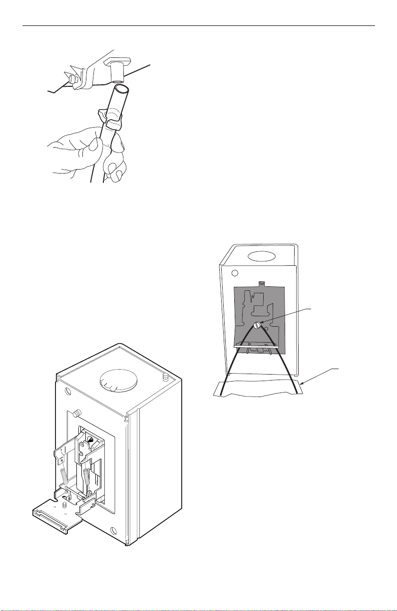
4. Connect a 1/2 in. (13 mm) drain tube to the humid-
ifier drain fitting and run to the floor drain (see Fig.
8).
a. Slide the drain clamp over the tubing.
b. Push the tubing over the drain nipple on the
humidifier.
c. Hand-tighten the clamp around the tubing to
secure the humidifier drain.
d. Fasten the drain tubing (can use duct tape)
along the route to prevent movement and
ensure downward slope for correct drainage.
NOTE: Cut tubing to correct length so the tubing termi-
nates at the drain.
Fig. 8. Installing the drain tubing.
Installing the Sail Switch
Adapting Switch to Air Flow Direction
The S688A Sail Switch has two counterbalancing springs
in place as shown in Fig 9. These springs offset the effect
of gravity for air flow direction.
IMPORTANT:
Do not use the sail switch with both springs
attached. Be sure to select air flow direction and
remove spring(s) not required for installation.
Fig. 9. Adapting sail switch to air flow direction or
mounting position.
M20175
SCREW DRIVER
WATER LINE
M20176
BRASS COMPRESSION NUT
PLASTIC
COMPRESSION RING
BRASS INSERT
M20177
UP
M3014
HE360 HUMIDIFIER AND INSTALLATION KIT
5 69-1646EF
• Vertical downward air flow: Leave the spring in
place that is attached to the bracket marked Down.
Remove the spring that is attached to the bracket
marked Up.
• Vertical upward air flow: Leave the spring in place
that is attached to the bracket marked Up. Remove
the spring that is attached to the bracket marked
Down.
• Horizontal air flow: Remove both springs.
1. Mount the template (provided with the sail switch)
at the desired location.
NOTE: Be sure the arrow (indicating air flow) points in
the correct direction.
a. For horizontal mounting, level the long dimen-
sion shown on the template.
b. For vertical mounting, plumb the long dimen-
sion.
2. Cut the hole (indicated on the template) in the duct-
work.
3. Center punch the screw holes indicated and drill
out with a 1/8 in. (13 mm) drill.
4. Attach the sail to the switch as shown in Fig 10.
Fig. 10. Attaching sail to switch.
5. Press together the sides of the wire loop. Insert the
sail into the duct. (When in the Off position, the sail
should point into the direction of airflow as shown
in Fig.11.)
Fig. 11. Inserting sail switch in direction of airflow.
6. Secure the switch by using the sheet metal screws
provided.
7. After wiring, snap on the cover.
Installing the Humidistat
Installing on Mounting Duct
1. Apply the template to the duct location chosen
for the humidistat. Make sure the template is
level before drilling the holes.
2. Refer to the template (provided with the H8908
Humidistat Installation Instructions) to drill the
control assembly opening and mounting holes
for the H8908.
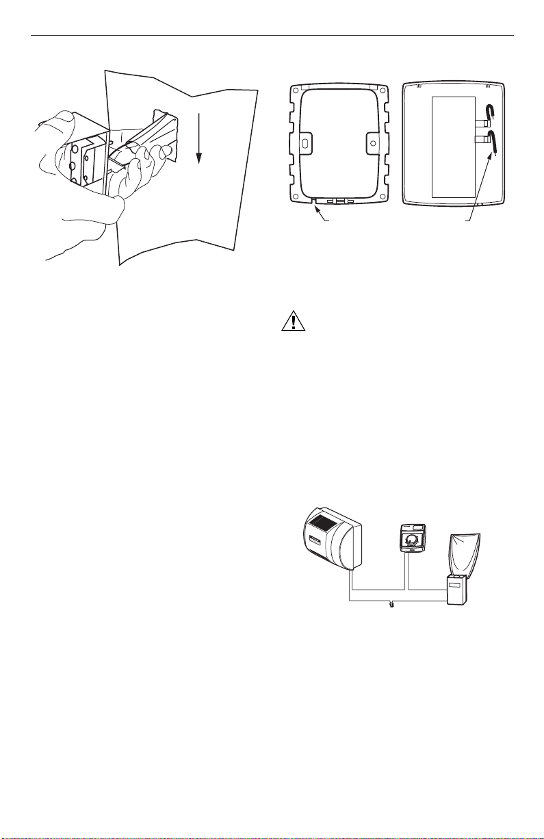
3. Remove the H8908 case from the base.
4. Position the foam gasket on the H8908 base.
5. Position the base on the duct with the arrow up.
6. Secure the base to the duct using the four
1 in. (25 mm) mounting screws provided with humi-
distat.
7. Connect the low-voltage wires to the leads and
replace the H8908 case. See Fig. 12.
NOTE: For wall mounting instructions, see the H8908
Installation Instructions.
Fig. 12. Humidistat base and rear view.
– LOOSEN SETSCREW
– INSERT SAIL
– TIGHTEN SETSCREW
SAIL
M20181
M20178
AIRFLOW
M20179
WIRE SLOT
HUMIDISTAT WIRES
HUMIDISTAT BASE REAR OF HUMIDISTAT
HE360 HUMIDIFIER AND INSTALLATION KIT
69-1646EF 6
WIRING
CAUTION
Hazardous Voltage.
Can cause personal injury or equipment
damage.
Disconnect power supply before installing or
servicing equipment.
IMPORTANT
All wiring must comply with applicable local
code, ordinances and regulations.
Wire the humidifier solenoid valve, sail switch, humidistat
and transformer.See Fig. 13.
Fig. 13. Wiring the controls.
1. Run the two-strand thermostat wire from the
humidifier to the humidistat, and from the humidis-
tat to the sail switch.
2. Cut lengths of thermostat wire to reach between
components, leaving adequate wire at both ends
for connections.
NOTE: Humidistat and sail switch can be wired in any
order.
3. At the humidifier, connect the black and white con-
ductors to the two yellow humidifier wires. (The red
wires from the humidifier are not used.)
4. At the humidistat, connect both black conductors to
the two humidistat terminals. Use a wire nut to con-
nect together the two white conductors.
5. At the sail switch, connect the black and white con-
ductors to the Com and NO sail switch terminals
(NC terminal is not used).
TESTING HUMIDIFIER OPERATION
Checklist
❑ Humidifier is level.
❑ Control wiring was reviewed using circuit diagram.
❑ Humidifier is plugged in.
❑ Feed line has no kinks.
❑ Drain line slopes continuously down and ends at floor
drain.
❑ Water hose inside humidifier is connected to
PerfectFlow™ water distribution tray.
After installation use the following steps to check the
humidifier operation:
1. Turn on the power and the water supply
2. Turn the H8908 Humidistat to On and turn on the
heat by setting the thermostat to 10ºF (6ºC) above
room temperature.
IMPORTANT
The furnace blower must be on to activate the
humidifier.
3. Make sure that water is flowing out of the drain
hose. If water does not flow, see Troubleshooting
Your Humidifier section.
4. Check for leaks.
5. Reset the thermostat and H8908 Humidistat to a
comfortable setting for automatic operation.
H
u
m
i
d
i
t
y
C
o
n
t
r
o
l
R
é
g
u
l
a
t
e
u
r
d
'
h
u
m
i
d
i
t
é
-
2
0
¡
F
-
1
0
¡
F
0
¡
F
+
1
0
¡
F
+
2
0
¡
F
O
v
e
r
2
0
¡
F
1
5
%
2
0
%
2
5
%
3
0
%
3
5
%
4
0
%
H
U
M
I
D
I
T
Y
S
E
T
T
I
N
G
O
U
T
D
O
O
R
T
E
M
P
E
R
A
T
U
R
E
-
3
0
¡
C
-
2
5
¡
C
-
2
0
¡
C
-
1
0
¡
C
-
5
¡
C
O
v
e
r
0
¡
C
M20205
BLACK
WHITEWHITE
HUMIDIFIER
SOLENOID
VALVE
HUMIDISTAT
SAIL
SWITCH
HE360 HUMIDIFIER AND INSTALLATION KIT
7 69-1646EF
OPERATION
How Your Humidifier Works
Your Honeywell humidifier uses the principle that vapor
(evaporated water) is created when warm air blows over
a water-soaked area. As the vapor circulates, the relative
humidity rises.
Your humidity control monitors the relative humidity and
activates the humidifier accordingly. The humidifier has a
water supply that dispenses water evenly over a
humidifier pad. The warm dry air, from the furnace,
passes over the humidifier pad and picks up the moist air
to circulate it throughout your home.
Humidified air feels warmer and more comfortable so you
may be able to lower your thermostat heating setpoint,
which saves money on your heating fuel bills. The end
result is that your humidifier gives you a comfortable
environment that is also energy efficient.
Controlling Your Humidity Settings
Your H8908 Humidistat controls your humidifier.
• Choose the humidity control setting using the
combination of relative humidity/outdoor temperature
setting scale on your humidity control dial.
• Match the dial setting to the outdoor temperature to
optimize the humidity level while reducing the
moisture condensation on your windows. See Table 2
to adjust the humidity control to the recommended
setting.
NOTE: As the outside temperature drops, a lower
humidity setting is recommended to accommo-
date dewpoint effects. These settings should
reduce the accumulation of moisture and ice on
windows and other areas of the home.
• Adjust the humidity control setting to adjust for indoor
activities such as cooking, showering and clothes
drying, which can cause excessive levels of humidity
that can accumulate moisture on your windows.
NOTE: If these activities persist for more than a few
hours, set the humidity control to the lowest set-
ting to turn off the humidifier. If the condition
does not improve, ventilate your home to
remove the moisture.
MAINTAINING YOUR HUMIDIFIER
A regular maintenance program prolongs the life of your
humidifier and makes your home more comfortable. The
frequency of cleaning depends on the condition of your
water.
You can use either hard or soft water in your humidifier,
but hard water mineral deposits are more difficult to clean
than soft water deposits.
Use the following procedure to clean your Honeywell
humidifier.
WARNING
Serious Personal Injury Hazard.
Can cause electrical shock and injury from
moving parts.
Disconnect power and shut off water supply
before removing cover.
IMPORTANT
Never oil any part of the humidifier.
Every 1 to 3 Months (Depending on Water
Quality)
1. Disconnect the power and turn off the humidifier
water supply.
2. Remove the humidifier cover by unplugging the
connector and loosening the thumb screw. Grasp
the cover near the bottom and pull toward you. See
Fig. 14.
3. Remove the humidifier pad assembly from the
humidifier by grasping the top of the tray and pull-
ing it toward you.
4. Lift the tray off the pad.
5. Gently pinch the water nozzle catches inward until
you can lift the water nozzle off the tray.
6. Carefully remove any mineral deposits from the
tray and frame. Be sure the frame drain hole has
nothing blocking it.
Fig. 14. Cleaning your humidifier.
Table 2. Setting Your Humidistat.
When Outside
Temperature is:
Use This Control
Setting:
-20°F (-29°C) 15
-10°F (-23°C) 20
0°F (-18°C) 25
+10°F (-12°C) 30
+20°F (-7°C) 35
Above 20°F (-7°C) 40
M12809
COVER
ASSEMBLY
HUMIDIFIER
PAD ASSEMBLY
FEED TUBE NOZZLE
WATER
DISTRIBUTION TRAY
HUMIDIFIER
HOUSING
THUMB
SCREW

HE360 HUMIDIFIER AND INSTALLATION KIT
69-1646EF 8
7. Disconnect the drain hose from the drain fitting on
the bottom of the humidifier housing.
8. Clean the drain fitting, if necessary.
9. Bend the drain hose to loosen any mineral depos-
its.
10. Flush the drain hose with pressurized water (a run-
ning tap) to clean the hose.
11. Reattach the drain hose to the drain fitting.
12. Snap the water nozzle back on the tray.
13. Be sure the marked end of the pad is facing up.
Place the tray on the new pad.
14. Place the humidifier pad assembly in the humidifier
housing. Be sure the water feed tube is placed in
the guide slots.
15. Replace the humidifier cover.
16. Verify the humidifier operation by following the
steps in the Checking Your Humidifier for Correct
Operation section.
CHECKING YOUR HUMIDIFIER FOR
CORRECT OPERATION
After winter startup or servicing, use the following steps
to check your humidifier operation:
1. Turn on the humidifier power and water supply.
2. Turn the humidistat to its highest setting and set
the thermostat to 10°F (6°C) above the room tem-
perature.
3. Observe that water is flowing out of the drain hose.
NOTE: The furnace blower must be running to activate
the humidifier.
4. Reset the thermostat and humidistat to a comfort-
able setting for automatic operation.

HE360 HUMIDIFIER AND INSTALLATION KIT
9 69-1646EF
TROUBLESHOOTING YOUR HUMIDIFIER
Table 3. Troubleshooting Humidifier.
Problem What to look for What to do
Water leakage Leaking joints. Shut off water.
Tighten connections.
Brass tubing inserts Verify that brass tubing inserts are used.
Saddle valve leaking. Verify rubber pad is installed on saddle valve.
No water to drain. Electrical Verify control circuit wiring.
Check all connections.
Humidistat Turn humidistat up and down and listen for contact
to click.
Humidifier power Verify that outlet has power.
Sail switch Remove sail cover; turn on furnace fan and listen
for faint click.
Verify that sail can move freely in duct; check sail
switch instructions to trim sail, if necessary.
Solenoid After verifying other wiring components, turn on
furnace fan, turn humidistat up and down, and listen
for solenoid to click.
Plumbing Verify plumbing connections.
Check for kinks.
Saddle valve Verify that needle pierces water line and then backs
out needle to open valve.
Humidifier Remove cover and verify that water flows into
distribution tray.
Drain tubing Verify no obstructions.
Low humidity Furnace blower not operating. • Reset circuit breaker or check for blown fuse.
• Check that the furnace power is on.
• Check all external wiring connections.
• Check the humidity control setting.
• Call a professional heating contractor.
Rapid air changes. Drafts
(cold air is dry and is an added
load to the humidifier).
• Keep doors and windows closed.
• Close fireplace damper when not in use.
• Keep exhaust fan running time to a minimum.
• Seal around doors and windows.
High humidity Condensation on walls. • Turn off humidity control and water until
condensation is completely evaporated.
Heavy condensation on
windows.
• Turn humidity control down low enough to
eliminate condensation caused by moisture from
bathing, mopping, cooking, etc. If moisture
persists, more ventilation is needed.

HE360 HUMIDIFIER AND INSTALLATION KIT
69-1646EF 10
LIMITED ONE-YEAR WARRANTY
Honeywell warrants this product, excluding humidifier pad, to be free from defects in the workmanship or materials,
under normal use and service, for a period of one (1) year from the date of purchase by the consumer. If, at any time
during the warranty period, the product is defective or malfunctions, Honeywell shall repair or replace it (at Honeywell’s
option) within a reasonable period of time.
If the product is defective, return it, with a bill of sale or other dated proof of purchase, to the retailer where you
purchased it.
This warranty does not cover removal or reinstallation costs. This warranty shall not apply if it is shown by Honeywell
that the defect or malfunction was caused by damage which occurred while the product was in the possession of a
consumer.
Honeywell’s sole responsibility shall be to repair or replace the product within the terms stated above. HONEYWELL
SHALL NOT BE LIABLE FOR ANY LOSS OR DAMAGE OF ANY KIND, INCLUDING ANY INCIDENTAL OR
CONSEQUENTIAL DAMAGES RESULTING, DIRECTLY OR INDIRECTLY, FROM ANY BREACH OF ANY
WARRANTY, EXPRESS OR IMPLIED, OR ANY OTHER FAILURE OF THIS PRODUCT. Some states do not allow the
exclusion or limitation of incidental or consequential damages, so this limitation may not apply to you.
THIS WARRANTY IS THE ONLY EXPRESS WARRANTY HONEYWELL MAKES ON THIS PRODUCT. THE
DURATION OF ANY IMPLIED WARRANTIES, INCLUDING THE WARRANTIES OF MERCHANTABILITY AND
FITNESS FOR A PARTICULAR PURPOSE, IS HEREBY LIMITED TO THE ONE YEAR DURATION OF THIS
WARRANTY. Some states do not allow limitations on how long an implied warranty lasts, so the above limitation may
not apply to you.
This warranty gives you specific legal rights, and you may have other rights which vary from state to state.
If you have any questions concerning this warranty, please write to Honeywell Customer Care, 1885 Douglas Drive,
Minneapolis, MN55422. In Canada, write Retail Products ON15-02H, Honeywell Limited/Honeywell Limitée, 35
Dynamic Drive, Scarborough, Ontario M1V 4Z9.

HE360 HUMIDIFIER AND INSTALLATION KIT
11 69-1646EF

69-1646EF G.H. 9-02 www.honeywell.com/yourhome
HE360 HUMIDIFIER AND INSTALLATION KIT
Printed in U.S.A. on recycled
paper containing at least 10%
post-consumer paper fibers.
Automation and Control Solutions
Honeywell Honeywell Limited-Honeywell Limitée
1985 Douglas Drive North 35 Dynamic Drive
Golden Valley, MN 55422 Scarborough, Ontario
M1V 4Z9
® Marque de commerce déposée aux É.-U.
Copyright © 2002 Honeywell • Tous droits réservés •
INSTRUCTIONS D'INSTALLATION/MANUEL DU PROPRIÉTAIRE
69-1646EF
Humidificateurs HE360 et trousse
d'installation
BIENVENUE…
dans un environnement tout confort, où l'air est humidifié.
Avec votre humidificateur Honeywell, vous constaterez
que votre peau sera moins sèche. Vous remarquerez
aussi, de jour en jour, une diminution de l'irritation de
votre gorge et de vos voies nasales causée par les
allergies et l'asthme.
Vous venez de faire le premier pas pour éliminer le
phénomène de décharge électrique lorsque vous
marchez sur une moquette, puis touchez le téléviseur,
l'ordinateur, une poignée de porte en métal ou votre
animal. Enfin, l'air humidifié fait toute la différence car il
préserve également les meubles et les boiseries.
Félicitations ! En rendant votre maison plus confortable,
vous venez de réaliser un investissement important.
APPLICATION
Cette trousse comprend un humidificateur HE360 et un
humidistat H8908 de Honeywell ainsi que tous les
accessoires nécessaires à l'installation.
INSTALLATION
Avant d'installer ce produit
Il est important d'identifier tous les accessoires
nécessaires (fournis) énumérés au Tableau 1 et d'avoir
sous la main les bons outils.
Accessoires nécessaires (fournis)
Tableau 1. Accessoires nécessaires.
Outils nécessaires
Les outils nécessaires à l’installation :
• Cisailles à tôle.
• Tournevis.
• Clé ouverte ou réglable.
• Perceuse ou poinçon.
• Niveau.
Quantité Accessoires
6,2 m (20 pi) Fil de thermostat à deux brins,
grosseur 18
6,2 m (20 pi) Tuyau d'arrivée d'eau 6,35 mm
(1/4 po) diam. ext.
3,1 m (10 pi) Tuyau de vidange 12,7 mm
(1/2 po) diam.
1 sac Quincaillerie de raccordement
et de fixation :
Serre-fils (4)
Vis à tôle n
o
8 (18)
Bride de tuyau de vidange
Brides de fixation du tuyau
d'arrivée d'eau (6)
Garnitures en laiton (2)
Anneaux de compression
en plastique (2)
1 Interrupteur à ailette
1 Humidistat H8908
1 sac Ensemble robinet-vanne à
étrier :
Robinet-vanne à étrier et
bride supérieure (1)
Bride inférieure filetée (1)
Boulons (2)
Joint en caoutchouc (1)
Garniture en laiton (1)
Douille en plastique (1)
HUMIDIFICATEURS HE360 ET TROUSSE D'INSTALLATION
69-1646EF 2
Choix du meilleur endroit pour l'humidificateur
MISE EN GARDE
Risques liés à une température ou une
pression statique élevée.
Peut causer des dommages matériels ou
endommager l'équipement.
Installer l'humidificateur dans un endroit où la
température ambiante se situe entre 0° C (32 °F)
et 71 °C (160 °F).
Ne pas installer l'humidificateur dans un endroit
exposé au gel.
S'assurer que la pression statique de
l'alimentation dans le plenum ne dépasse pas
0,4 po C.E. et que la pression de l'eau ne
dépasse pas 124 psi.
Déterminer l'endroit où installer l'humidificateur
sur le plenum (flux d'air chaud). Voir la Fig. 1.
• S'assurer qu'à l'endroit choisi, le serpentin en A de
l'appareil de climatisation ne risque pas d'être
endommagé au cours de l'installation.
• Ne pas installer l'humidificateur sur le boîtier de
l'appareil de chauffage.
• S'assurer qu'il y a suffisamment d'espace devant
l'humidificateur et au-dessus pour enlever le
couvercle et faire l'entretien.
— Installer l'humidificateur au moins 78 mm (3 po)
au-dessus du boîtier de l'appareil de chauffage
afin de laisser un espace suffisant pour le mon-
tage de l'électrovanne et du tuyau de vidange.
— Installer l'humidificateur dans un endroit où l'air
est conditionné pour prévenir le gel.
.
Fig. 1. Emplacements types de l'humidificateur.
Choix de l'endroit d'arrivée d'eau
• L'humidificateur fonctionne avec de l'eau dure ou de
l'eau douce. L'eau peut être chaude ou froide. Le
débit d'eau nécessaire pour imbiber l'écran
évaporateur et transformer l'eau en vapeur est de
13 litres/h (3,5 gal/h) lorsque l'humidificateur est en
marche.
• S'assurer que le tuyau d'arrivée d'eau de 6,2 m (20 pi)
fourni permet de raccorder l'alimentation d'eau
(robinet-vanne à étrier) à l'électrovanne de
l’humidificateur.
Repérage du siphon de sol le plus près
• Choisir un endroit avec accès au siphon de sol pour
l'évacuation de la condensation du climatiseur et la
vidange de l'humidificateur.
• S'il n'y a pas de siphon à proximité, il est préférable
d'installer l'humidificateur central à tambour ou à
disque de Honeywell. S'assurer que le tuyau de
vidange de 3,1 m (10 pi) est suffisamment long et
permet de raccorder le tuyau de vidange de
l'humidificateur au siphon de sol.
Choix de l’emplacement de l'interrupteur à
ailette
• Choisir un endroit dans la gaine de reprise d'air froid
où l'interrupteur à ailette sera directement et
pleinement exposé au flux d'air.
— L'interrupteur à ailette détecte si le ventilateur de
l'appareil de chauffage est en marche.
• Choisir un endroit où la gaine d'air mesure au moins
305 mm (12 po) de hauteur et 203 mm (8 po) de
largeur afin que l'ailette en marche ne nuise pas à la
circulation de l'air dans la gaine.
— Le flux d'air à l'endroit choisi pour l'interrupteur à
ailette peut être vertical (vers le haut ou vers le
bas) ou horizontal.
IMPORTANT
La durée de l'interrupteur à ailette pourrait être
réduite si le S688 est installé dans la gaine d'air
chaud.
• Monter l'interrupteur à au moins 152 mm (6 po) en
amont d'un coude ou d'un raccordement, et à au
moins 381 mm (15 po) en aval d'un coude ou d'un
raccordement.
• Installer l'interrupteur du côté opposé au flux d'air
dans la gaine. (Voir les Fig. 1-3, dans les Instructions
d'installation du S688.)
Choix de l’emplacement de l'humidistat
• Installer l'humidistat dans le plenum de reprise ou sur
le mur d'une pièce occupée.
— L'installation du circuit de câblage des com-
mandes est beaucoup plus simple lorsque l'humi-
distat est installé dans le plenum de reprise.
Dans la gaine de reprise, l'humidistat doit être installé en
amont de l'humidificateur ou en dérivation de manière
qu'il puisse détecter avec exactitude l'humidité relative
dans la pièce. Installer l'appareil à au moins 203 mm
(8 po) en amont de l'humidificateur dans la gaine de
reprise. (Voir la Fig. 2.)
Fig. 2. Choix de l'endroit où installer l'humidistat
dans la gaine.
MF12808A
HORIZONTAL
APPAREIL
SURBAISSÉ
REPRISE
REPRISE
EPRISE
APPAREIL
VERTICAL
REPRISE
CO
URANT
DESC
E
N
DANT
AUTRE EMPLACEMENT
AIR
REPRIS
AIR
REPRIS
AU MOINS
152 mm (6 po)
AU MOINS
381 mm (15 po)
MEILLEUR
EMPLACEMENT
GAINE DE REPRISE
MF12831
HUMIDIFICATEURS HE360 ET TROUSSE D'INSTALLATION
3 69-1646EF
Repérage de la prise électrique 120 V la plus
près
• Choisir un endroit près d'une prise. S'il n'y a pas de
prise, en faire installer une par un électricien.
• S'assurer que le cordon de l'humidificateur est
suffisamment long et qu'il peut être branché dans la
prise.
• S'assurer que le fil de thermostat de 6,2 m (20 pi) est
suffisamment long pour être branché de
l'électrovanne de l'humidificateur à l'interrupteur à
ailette et à l'humidistat.
Installation de l'humidificateur
AVERTISSEMENT
Risque de choc électrique.
Peut causer des blessures ou des dommages
matériels.
Ne pas couper ou percer un appareil électrique
ou de conditionnement d'air.
MISE EN GARDE
Arêtes vives présentant un danger au
moment de l'installation.
Peut causer des blessures.
Porter des gants et des lunettes de sécurité.
1. Couper l'alimentation du système de conditionne-
ment de l'air dans le tableau à disjoncteurs.
2. Tracer une ligne de niveau sur le plenum, à
l'endroit où l'humidificateur sera installé. (La mise
au niveau assure le rendement optimal de l'humi-
dificateur.)
3. Prendre le gabarit dans la boîte (pièce 69-16510).
4. Fixer le gabarit avec du ruban adhésif et en tracer
le contour.
5. Enlever le gabarit et découper soigneusement une
ouverture rectangulaire.
6. Démonter l'humidificateur, enlever le couvercle et
retirer l'ensemble écran évaporateur. Voir la Fig. 3.
Fig. 3. Démontage de l'humidificateur.
7. Placer les pinces de fixation comme l’indique la
Fig. 4.
.
Fig. 4. Position des pinces de fixation.
8. S'assurer que le boîtier de l'humidificateur est de
niveau, puis le placer de manière que les attaches
de plastique soient sur l'arête de la tôle inférieure
de l'ouverture. S'il y a lieu, aplatir les bords à l'aide
de pinces. Voir la Fig. 5.
9. Enfoncer les pinces jusqu’à ce qu’elles soient bien
fixées.
10. Percer les trous et insérer trois vis à tôle dans la
partie supérieure du boîtier de l’humidificateur.
Puis, fixer le boîtier de l'humidificateur à l’aide des
trois autres vis à tôle.
Fig. 5. Installation de l'humidificateur sur une gaine.
11. Remettre l'ensemble écran évaporateur dans le
boîtier de l'humidificateur.
IMPORTANT
S’assurer que le tube d’arrivée d’eau est
raccordé et qu’il n’est pas coincé ou pincé.
12. Remettre le couvercle dans les fentes et le fixer au
moyen de la vis à oreilles au bas du couvercle.
MF12809
COUVERCLE
ENSEMBLE ÉCRAN
ÉVAPORATEUR
D'HUMIDIFICATEUR
GICLEUR D'ARRIVÉE
D'EAU
PLATEAU DE
DISTRIBUTION D’EAU
BOÎTIER
D'HUMIDIFICATEUR
VIS À OREILLES
MF12813
PINCE DE FIXATION
PINCE DE FIXATION
GAINE
NIVEAU
IS
À
ÔLE (4)
ATTACHES EN
PLASTIQUE (2)
TUYAU DE VIDANGE
MF20204
OUVERTURE
VERS LA GAINE
D'AIR
HUMIDIFICATEURS HE360 ET TROUSSE D'INSTALLATION
69-1646EF 4
Raccordement des tuyaux
L'humidificateur fonctionne avec de l'eau chaude ou de
l'eau froide et avec de l'eau dure ou de l'eau douce.
1. Fermer le robinet d'arrêt.
MISE EN GARDE
Produits chimiques dangereux.
Peut causer des blessures ou des dommages
matériels.
Ne pas utiliser la tuyauterie reliée au système de
climatisation.
Ne pas utiliser de canalisations de gaz.
2. Utiliser le robinet-vanne à étrier autoperceur
(fourni) pour percer le tuyau d'arrivée d'eau à
l'endroit choisi. Voir la Fig. 8. Si le tuyau est en
acier galvanisé, vider la canalisation et percer un
trou de 3/17 po pour le robinet-vanne à étrier.
REMARQUE : Le robinet-vanne à étrier ne doit pas
servir de régulateur de débit d'eau. Le
robinet-vanne doit être soit ouvert soit
fermé.
IMPORTANT
Pour éviter que des débris ne bloquent le filtre
sur la canalisation de l'électrovanne, il est
important d'installer la poignée du robinet-
vanne à étrier de sorte qu'elle pointe vers le
plafond.
.
Fig. 6. Installation du robinet-vanne à étrier.
3. Utiliser un tuyau de 6 mm (1/4 po) de diam. ext.
pour raccorder le robinet-vanne à étrier à l'entrée
de l'électrovanne sur l'humidificateur. (Voir la
Fig. 7.)
a. Placer l'écrou à compression en laiton sur le
tuyau.
b. Placer la garniture en laiton à l'extrémité du
tuyau.
c. Glisser l'anneau de compression en plastique
sur le tuyau. (Mettre de côté l'anneau de com-
pression en cuivre fourni avec le robinet.)
REMARQUE : Pour empêcher les fuites, avec des
tuyaux en plastique, utiliser des anneaux
en plastique (Delrin). N'utiliser des
anneaux en cuivre qu'avec des tuyaux en
cuivre.
d. Insérer le tuyau dans le raccord de l'électro-
vanne et serrer l'écrou de compression tout en
prenant soin de soutenir la vanne.
REMARQUE : Ne pas trop serrer l'écrou à compres-
sion. Un serrage moyen empêche les
fuites.
e. Répéter les étapes « a » à « d » pour le rac-
cord de l'électrovanne.
f. Fixer le tuyau à l'aide des brides fournies
Fig. 7. Installation du tuyau d'arrivée d'eau.
4. Relier un tuyau de vidange de 13 mm (1/2 po) au
raccord de vidange de l'humidificateur et le diriger
vers le siphon de sol (voir la Fig. 8).
a. Glisser la bride du tuyau de vidange sur le
tuyau.
b. Passer le tuyau par-dessus le raccord fileté du
tuyau de vidange de l'humidificateur.
c. Serrer manuellement la bride sur le tuyau pour
bien le fixer sur l'humidificateur.
d. Attacher le tuyau de vidange avec du ruban
pour canalisations, par exemple, afin
d'empêcher qu'il ne bouge. Le tuyau doit
présenter une pente descendante pour assurer
une vidange efficace.
REMARQUE : Couper le tuyau à la longueur nécessaire
pour qu'il atteigne le siphon.
MF20175
TOURNEVIS
CANALISATION
D'EAU
MF20176
ÉCROU À COMPRESSION
EN LAITON
ANNEAU DE
COMPRESSION
EN PLASTIQUE
GARNITURE
EN LAITON
HUMIDIFICATEURS HE360 ET TROUSSE D'INSTALLATION
5 69-1646EF
.
Fig. 8. Installation du tuyau de vidange.
Installation de l'interrupteur à ailette
Installation de l'interrupteur en fonction de la
direction du flux d'air
L'interrupteur à ailette S688A comprend deux ressorts
d'équilibrage (Voir la Fig. 9.) Ces ressorts servent à
compenser l'effet de gravité en fonction de la direction du
flux d'air.
IMPORTANT
Ne pas laisser les deux ressorts attachés.
Sélectionner le sens de la circulation de l'air,
puis enlever le ou les ressorts non nécessaires.
.
Fig. 9. Installation de l'interrupteur à ailette suivant
la direction du flux d'air ou la position de montage.
• Courant d'air vertical, vers le bas : Laisser en place
le ressort attaché au support marqué «Down».
Enlever le support attaché au support marqué «Up»
• Courant d'air vertical, vers le haut : Laisser en
place le ressort attaché au support marqué «Up».
Enlever le support attaché au support marqué
«Down».
• Courant d'air horizontal : Enlever les deux ressorts.
1. Placer le gabarit fourni avec l'interrupteur à ailette
à l'endroit choisi.
REMARQUE : S'assurer que la flèche indiquant le sens
de la circulation de l'air pointe dans la
bonne direction.
a. Dans le cas d'un montage horizontal, placer le
long côté horizontalement à l'aide d'un niveau.
b. Dans le cas d'un montage vertical, placer le
long côté verticalement à l'aide d'un niveau.
2. Percer le trou (indiqué sur le gabarit) dans la gaine.
3. À l'aide d'un pointeau, faire les trous de vis
indiqués, puis avec une perceuse, faire des trous
de 13 mm (1/8 po).
4. Fixer l'ailette à l'interrupteur de la façon indiquée à
la Fig. 10.
.
Fig. 10. Fixation de l'ailette à l'interrupteur.
5. Presser ensemble les côtés du fil métallique. Intro-
duire l'ailette dans la gaine. (En position Off,
l'ailette doit pointer dans la direction du flux d'air
comme à la Fig. 13.)
M20177
UP
M3014
DESSERRER LA VIS
DE BLOCAGE
INSÉRER L'AILETTE
SERRER LA VIS
DE BLOCAGE
AILETTE
MF20181
HUMIDIFICATEURS HE360 ET TROUSSE D'INSTALLATION
69-1646EF 6
.
Fig. 11. Introduction de l'interrupteur à ailette
suivant la direction du flux d'air.
6. Fixer l'interrupteur au moyen des vis de blocage
fournies.
7. Une fois l'installation terminée, enclencher le cou-
vercle.
Installation de l'humidistat
Montage sur gaine
1. Placer le gabarit sur la gaine, à l'endroit où
sera installé l'humidistat. S'assurer que le
gabarit est de niveau avant de percer les trous.
2. Utiliser le gabarit fourni avec les instructions
d'installation de l'humidistat H8908 pour percer
l'ouverture pour les appareils et les trous de
montage du H8908.
3. Retirer le boîtier du socle du H8908.
4. Placer le joint en mousse sur le socle du H8908.
5. Placer le socle sur la gaine, la flèche vers le haut.
6. Fixer le socle sur la gaine à l'aide des quatre vis de
montage de 25 mm (1 po) fournies avec l'humi-
distat.
7. Connecter les fils basse tension aux conducteurs
et remettre le boîtier du H8908. Voir la Fig. 12.
REMARQUE : Pour une installation au mur, consulter les
instructions d'installation du H8908.
.
Fig. 12. Socle et vue arrière de l'humidistat.
CÂBLAGE
MISE EN GARDE
Risque de choc électrique.
Peut causer des blessures ou des dommages
matériels.
Couper l'alimentation électrique avant de faire
l'installation ou l'entretien.
IMPORTANT
Tout le câblage doit être conforme aux codes et
règlements locaux.
Câbler l'électrovanne de l'humidificateur, l'interrupteur à
ailette, l'humidistat et le transformateur. Voir la Fig. 13.
.
Fig. 13. Câblage des appareils.
1. Passer le fil de thermostat à deux brins de l'humi-
dificateur à l'humidistat et de l'humidistat à
l'interupteur à ailette.
2. Couper des longueurs de fil à thermostat pour rac-
corder les éléments, en laissant suffisamment de fil
à chaque extrémité pour les raccords.
REMARQUE : Il n'y a pas d'ordre à suivre pour le
câblage de l'humidistat et de l'interrupteur
à ailette.
3. À l'humidificateur, raccorder les conducteurs blanc
et noir aux deux fils jaunes de l'humidificateur. (Les
fils rouges de l'humidificateur ne servent pas.)
MF20178
FLUX D'AIR
MF20179
FENTE POUR FIL
FILS DE L'HUMIDISTAT
SOCLE DE L'HUMIDISTAT
ARRIÈRE DE L'HUMIDISTAT
Humidity Cont
rol
Régulateur d'humidit
é
-
20
°F
-1
0 °F
0
°
F
+
10
°F
+
20
°
F
Over
2
0
°
F
1
5%
20
%
2
5
%
30%
35
%
40%
H
U
MID
IT
Y
S
E
TTIN
G
O
U
T
DO
O
R
T
E
MP
E
R
AT
U
R
E
-3
0
°C
-
25
°
C
-
2
0
°
C
-10
°
C
-
5
°C
Over
0
°
C
MF20205
NOIR
BLANCBLANC
ÉLECTROVANNE
DE L'HUMIDIFICATEUR
HUMIDISTAT
INTERRUPTEUR
À AILETTE

HUMIDIFICATEURS HE360 ET TROUSSE D'INSTALLATION
7 69-1646EF
4. À l'humidistat, raccorder les deux conducteurs
noirs aux deux bornes de l'humidistat. Connecter
ensemble les deux conducteurs blancs à l'aide
d'un serre-fils.
5. À l'interrupteur à ailette, raccorder les conducteurs
noir et blanc aux bornes Com et NO de l'interrup-
teur à ailette. (La borne NC ne sert pas.)
VÉRIFICATION DU FONCTIONNE-
MENT DE L'HUMIDIFICATEUR
LISTE DE VÉRIFICATION
❑ L'humidificateur est de niveau.
❑ Le câblage des commandes a été vérifié à l'aide du
schéma de circuit.
❑ L'humidificateur est branché.
❑ Le tuyau d'arrivée n'est pas pincé.
❑ Le tuyau de vidange présente une pente continue
vers le bas et se rend au siphon de sol.
❑ Le tuyau d'eau à l'intérieur de l'humidificateur est
raccordé au plateau de distribution d'eau
PerfectFlow
MC
.
Après l'installation, vérifier le fonctionnement de
l'humidificateur en suivant les étapes ci-dessous :
1. Mettre en marche l'humidificateur et ouvrir l'arrivée
d'eau.
2. Régler l'humidistat H8908 à ON et régler le ther-
mostat pour qu'il indique 6 °C (10 °F) de plus que
la température de la pièce.
IMPORTANT
Le ventilateur de l'appareil de chauffage doit
être en marche pour que l'humidificateur fonc-
tionne.
3. S'assurer que l'eau s'écoule du tuyau de vidange.
Dans le cas contraire, se reporter à la section
Dépannage de l'humidificateur.
4. Vérifier s'il y a des fuites.
5. Régler de nouveau le thermostat et l'humidistat
H8908 à une température de confort pour les faire
fonctionner automatiquement.
FONCTIONNEMENT
Fonctionnement de l'humidificateur
L'humidificateur fonctionne selon le principe suivant : la
vapeur (eau évaporée) se forme lorsque l'air chaud
souffle dans un endroit où il y a de l'eau; en circulant, la
vapeur fait augmenter l'humidité relative.
L’humidistat vérifie l’humidité relative et, s’il y a lieu, fait
fonctionner l’humidificateur. Le système d’arrivée d’eau
répartit uniformément l’eau sur l’écran évaporateur de
l’humidificateur. L’air sec et chaud qui sort de l’appareil
de chauffage passe sur l’écran évaporateur de
l’humidificateur et capte l’air humide pour le faire circuler
dans la maison.
L’air humidifié est plus chaud et il assure un meilleur
confort. Le point de consigne du thermostat peut donc
être abaissé, ce qui permet de diminuer les coûts de
chauffage. Avec un humidificateur, la maison devient
confortable et éconergétique.
Réglage de l'humidificateur
L'humidistat H8908 commande l'humidificateur.
• Régler l'humidistat à l'aide de l'échelle combinée
d'humidité relative et de température extérieure.
• Régler le cadran en fonction de la température
extérieure afin d'optimiser le niveau d'humidité et
d'éliminer la condensation dans les fenêtres.
(Consulter le Tableau 2 pour sélectionner le réglage
recommandé.)
REMARQUE : Lorsque la température extérieure baisse,
le réglage recommandé doit être abaissé
de manière à tenir compte du point de
rosée. Les réglages recommandés
devraient permettre de réduire l’accumu-
lation d’humidité et de glace dans les
fenêtres et ailleurs dans la maison.
• Le réglage de l'humidificateur doit être fait en fonction
des activités à l'intérieur, notamment la cuisson, les
douches et le séchage des vêtements. Ces activités
peuvent produire une humidité excessive et être la
cause de l'accumulation d'humidité dans les fenêtres.
REMARQUE : Si ces conditions durent plusieurs heures,
régler l'humidistat à la valeur la plus
basse pour arrêter l'humidificateur. S'il n'y
a aucun changement, il faudrait ventiler la
maison pour faire disparaître l'humidité.
Tableau 2. Réglage de l'humidistat.
ENTRETIEN DE L'HUMIDIFICATEUR
Un programme d’entretien à intervalles réguliers
prolonge la durée de l’humidificateur et assure un
meilleur confort. La fréquence de nettoyage varie selon
la qualité de l’eau.
L’humidificateur peut fonctionner avec de l’eau dure ou
de l’eau douce. Toutefois, les dépôts de sédiments d’eau
dure sont plus difficiles à enlever que ceux d’eau douce.
Pour nettoyer l'humidificateur, suivre les étapes
suivantes.
Température extérieure Réglage recommandé
-29 ºC (-20 ºF) 15
-23 ºC (-10 ºF) 20
-18 ºC (0 ºF) 25
-12 ºC (+10 ºF) 30
-7 ºC (+20 ºF) 35
Supérieure à -7 ºC (20 ºF) 40
HUMIDIFICATEURS HE360 ET TROUSSE D'INSTALLATION
69-1646EF 8
AVERTISSEMENT
Risque de blessures graves.
Les pièces mobiles peuvent causer des chocs
électriques ou des blessures.
Couper l’alimentation électrique et fermer
l’arrivée d’eau avant d'enlever le couvercle.
IMPORTANT
Ne jamais lubrifier les pièces de l'humidificateur.
À intervalles de 1 à 3 mois (selon la
qualité de l'eau)
1. Couper l’alimentation électrique et fermer l’arrivée
d’eau de l’humidificateur.
2. Enlever le couvercle de l’humidificateur en débran-
chant le connecteur et en dévissant la vis à
oreilles. Tenir la partie inférieure du couvercle et
tirer vers soi Voir la Fig. 14.
3. Enlever l’ensemble écran évaporateur en tenant la
partie supérieure du plateau et en le tirant vers soi.
4. Tirer vers soi un côté du cadre de l’ensemble écran
évaporateur pour dégager le plateau du cadre.
5. Appuyer délicatement sur les cliquets du gicleur
vers l’intérieur pour dégager le gicleur du plateau.
6. Gratter soigneusement les dépôts de sédiments au
fond du plateau et sur le cadre. S’assurer que l’ori-
fice de vidange n’est pas bloqué.
.
Fig. 14. Nettoyage de l'humidificateur.
7. Séparer le tuyau de vidange du raccord de vidange
à la partie inférieure du boîtier de l’humidificateur.
8. Nettoyer le raccord de vidange s'il y a lieu.
9. Plier le tuyau de vidange pour décoller les dépôts
de sédiments.
10. Rincer le tuyau de vidange avec de l’eau sous
pression (eau du robinet) pour le nettoyer.
11. Replacer le tuyau de vidange sur le raccord de
vidange.
12. Replacer le gicleur sur le plateau.
13. S’assurer que la partie marquée de l’écran évapo-
rateur est orientée vers le haut. Remettre le pla-
teau sur le cadre.
14. Mettre l’ensemble écran évaporateur d’humidifica-
teur dans le boîtier de l’humidificateur en appuyant
jusqu’à ce qu’il soit bien en place. S’assurer que le
tuyau d’arrivée d’eau n’est ni écrasé ni plié.
15. Remettre le couvercle sur l'humidificateur.
16. Pour vérifier le fonctionnement de l’humidificateur,
se reporter à la section Vérification du fonctionne-
ment de l’humidificateur.
VÉRIFICATION DU FONCTIONNE-
MENT DE L'HUMIDIFICATEUR
Après l'entretien ou la mise en marche pour l'hiver,
vérifier le fonctionnement de l'humidificateur en suivant
les étapes ci-dessous :
1. Mettre en marche l'humidificateur et ouvrir l'arrivée
d'eau.
2. Régler l'humidistat à la valeur la plus élevée et
régler le thermostat pour qu'il indique 6 °C (10 °F)
de plus que la température de la pièce.
3. Vérifier si l'eau circule dans le tuyau de vidange.
REMARQUE : Le ventilateur de l'appareil de chauffage
doit être en marche pour que l'humidifica-
teur fonctionne.
4. Régler le thermostat et l'humidistat pour qu'ils fonc-
tionnent automatiquement et assurent une
température de confort.
MF12809
COUVERCLE
ENSEMBLE ÉCRAN
ÉVAPORATEUR
D'HUMIDIFICATEUR
GICLEUR D'ARRIVÉE
D'EAU
PLATEAU DE
DISTRIBUTION D’EAU
BOÎTIER
D'HUMIDIFICATEUR
VIS À OREILLES

HUMIDIFICATEURS HE360 ET TROUSSE D'INSTALLATION
9 69-1646EF
DÉPANNAGE DE L'HUMIDIFICATEUR
Tableau 3. Dépannage de l'humidificateur.
Problème Ce qu'il faut vérifier Ce qu’il faut faire
Fuite d'eau Joints qui fuient. Couper l'alimentation d'eau.
Resserrer les raccords.
Garnitures de tuyau en laiton. Vérifier si les garnitures utilisées sont bien en laiton.
Fuite du robinet-vanne à étrier. Vérifier si l'écran évaporateur en caoutchouc est installé
sur le robinet-vanne à étrier.
L'eau ne s'écoule pas
vers le siphon
Électricité Vérifier le câblage du circuit de commande.
Vérifier toutes les connexions.
Humidistat Abaisser et augmenter le réglage de l'humidistat et vérifier
s'il se produit un bruit de contact.
Alimentation de l'humidistat Vérifier si la prise est sous tension.
Interrupteur à ailette Enlever le couvercle de l'ailette, mettre en marche le
ventilateur de l'appareil de chauffage et vérifier s'il y a un
déclic.
Vérifier si l'interrupteur de l'ailette bouge facilement dans la
gaine; s'il y a lieu, tailler l'ailette en suivant les instructions.
Électrovanne Vérifier les autres éléments de câblage, puis mettre en
marche le ventilateur de l'appareil de chauffage, abaisser
et augmenter le réglage de l'humidistat et vérifier s'il y a
déclic de l'électrovanne.
Tuyauterie Vérifier les raccords des tuyaux.
Vérifier si les tuyaux sont pincés.
Robinet-vanne à étrier Vérifier si le pointeau perce la ligne d'eau et revient en
position pour ouvrir le robinet-vanne.
Humidificateur Enlever le couvercle et vérifier si l'eau s'écoule dans le
plateau de distribution.
Tuyau de vidange Vérifier s'il y a blocage.
Faible humidité Le ventilateur de l'appareil de
chauffage ne fonctionne pas.
• Réenclencher le disjoncteur ou vérifier si le fusible est
bon.
• Vérifier si l'appareil de chauffage est sous tension.
• Vérifier les connexions externes.
• Vérifier le réglage de l'humidistat.
• Appeler un entrepreneur en chauffage.
Le renouvellement d'air est rapide
(courant d'air : l'air froid est sec et
représente une charge
supplémentaire pour
l'humidificateur).
• Garder les portes et les fenêtres fermées.
• Fermer le registre de la cheminée (foyer) lorsque celle-
ci n'est pas utilisée.
• Faire fonctionner le ventilateur d'extraction pendant une
période minimum.
• Rendre les portes et les ouvertures étanches.
Humidité élevée Condensation sur les murs Arrêter l'humidistat et fermer l'arrivée d'eau jusqu'à ce que
la condensation disparaisse complètement.
Forte condensation dans les
fenêtres
Abaisser suffisamment le réglage de l'humidistat pour
éliminer la condensation causée par les bains, le lavage
des planchers, la cuisson, etc. Si la condensation
persiste, il faut augmenter la ventilation.

HUMIDIFICATEURS HE360 ET TROUSSE D'INSTALLATION
69-1646EF 10
GARANTIE LIMITÉE DE UN AN
Honeywell garantit que ce produit, à l’exception de l’écran évaporateur de l’humidificateur, est exempt de tout vice de
fabrication ou de matière dans la mesure où il en est fait une utilisation et un entretien convenables et ce, pour une
période de un an à partir de la première date d’achat par le consommateur. En cas de défectuosité ou de mauvais
fonctionnement pendant la période de garantie, Honeywell réparera ou remplacera ledit produit (au choix de
Honeywell) dans un délai raisonnable.
Si le produit est défectueux, le consommateur, le consommateur doit le retourner au magasin où il a été acheté, en y
joignant la facture ou une preuve d’achat.
La présente garantie ne couvre pas les frais d’installation et de retrait de ce produit. La présente garantie ne
s’appliquera pas s’il est démontré par Honeywell que la défectuosité ou le mauvais fonctionnement du produit est
attribuable à un endommagement du produit alors que le consommateur l’avait en sa possession.
La responsabilité de Honeywell se limite à réparer ou à remplacer le produit conformément aux modalités
susmentionnées. HONEYWELL N’ASSUME AUCUNE RESPONSABILITÉ POUR QUELQUE DOMMAGE INDIRECT
QUE CE SOIT RÉSULTANT D’UNE VIOLATION QUELCONQUE D’UNE GARANTIE, EXPRESSE OU TACITE,
APPLICABLE AU PRÉSENT PRODUIT. Certains territoires et provinces ne permettent pas l’exclusion ou la restriction
des dommages indirects et, par conséquent, la présente restriction peut ne pas s’appliquer.
LA PRÉSENTE GARANTIE TIENT LIEU DE TOUTES LES AUTRES GARANTIES, EXPRESSES OU TACITES, ET
LES GARANTIES DE VALEUR MARCHANDE ET DE CONFORMITÉ À UNE FIN PARTICULIÈRE SONT PAR LES
PRÉSENTES EXCLUES APRÈS LA PÉRIODE DE UN AN DE LA PRÉSENTE GARANTIE. Certains territoires et
provinces ne permettent pas l’exclusion ou la restriction des dommages indirects et, par conséquent, la présente
restriction peut ne pas s’appliquer.
La présent garantie donne au consommateur des droits légaux spécifiques et peut-être certains autres droits qui
peuvent varier selon la province ou le territoire.
Pour tout renseignement concernant cette garantie, veuillez écrire à Honeywell Customer Care, 1885 Douglas Drive,
Minneapolis, MN55422. Au Canada, veuillez écrire à Honeywell Limitée-Honeywell Limited, Produits de détail, ON15-
02H, 35 Dynamic Drive, Scarborough (Ontario) M1V 4Z9.

HUMIDIFICATEURS HE360 ET TROUSSE D'INSTALLATION
11 69-1646EF

Imprimé aux États-Unis sur du papier
recyclé contenant au moins 10 %
de fibres post-consommation.
69-1646EF G.H. 9-02 www.honeywell.com/yourhome
HUMIDIFICATEURS HE360 ET TROUSSE D'INSTALLATION
Solutions de régulation et d'automatisation
Honeywell Honeywell Limited-Honeywell Limitée
1985 Douglas Drive North 35, Dynamic Drive
Golden Valley, MN 55422 Scarborough (Ontario)
M1V 4Z9