Loading ...
Loading ...
Loading ...
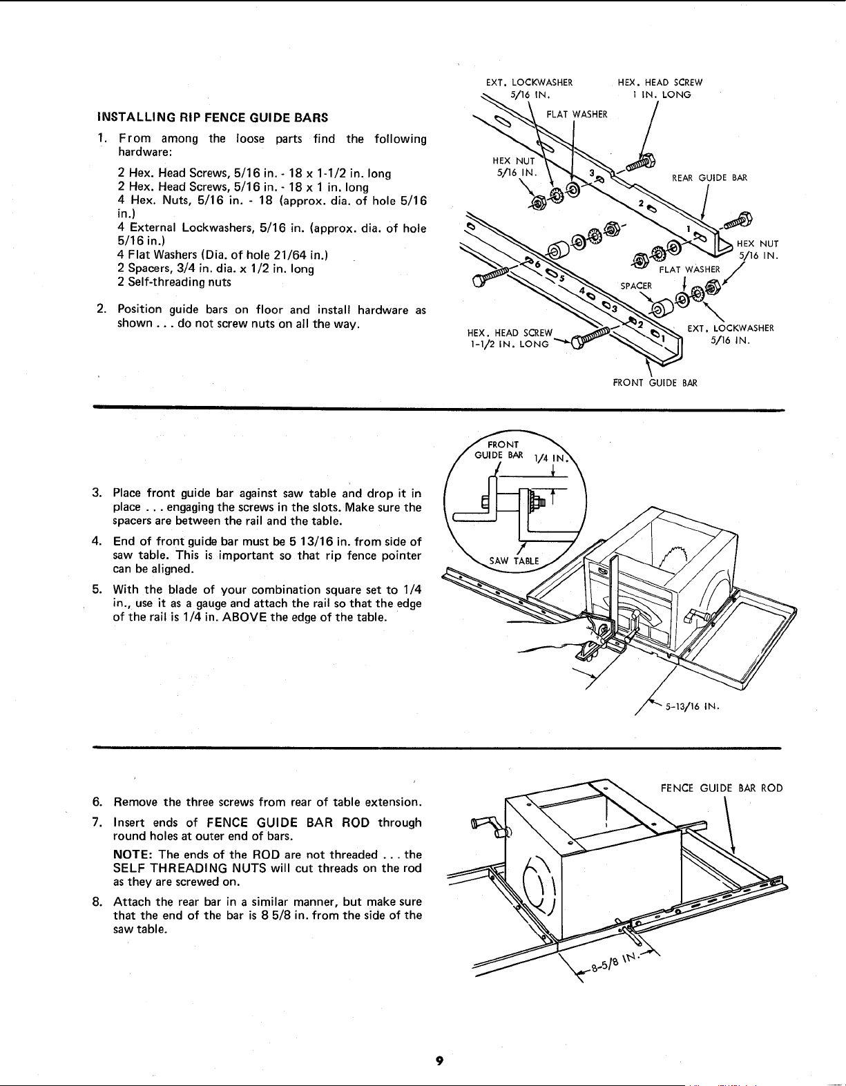
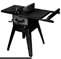
INSTALLING RIP FENCE GUIDE BARS
1. From among the loose parts find the following
hardwa re:
2 Hex. Head Screws, 5/16 in.- 18 x 1-1/2 in. long
2 Hex. Head Screws, 5/16 in.- 18 x 1 in. long
4 Hex. Nuts, 5/16 in. - 18 (approx. dia. of hole 5/16
in.)
4 External Lockwashers, 5/16 in. (approx. dia. of hole
5/16 in.)
4 Flat Washers (Dia. of hole 21/64 in.)
2 Spacers, 3/4 in. dia. x 1/2 in. long
2 Self-threading nuts
2. Position guide bars on floor and install hardware as
shown.., do not screw nuts on all the way.
EXT. LOCKWASHER
5/16 tN
FLAT WASHER
HEX NUT
5/16 iN.
\
HEX, HEAD SCREW
1-_,/2 IN= LONG
HEX. HEAD SCREW
1 IN. LONG
/
REAR GUIDE BAR
SPACER
FLAT WASHER
HEX NUT
5/16 IN.
/
EXT, LOCKWASHER
5/16 IN.
FRONT GUIDE BAR
/
3. Place front guide bar against saw table and drop it in
place ... engagingthe screws in the slots. Make sure the
spacersare between the rail and the table.
4. End of front guide bar must be 5 13/16 in. from side of
saw table. This is important so that rip fence pointer
\
can be aligned.
5. With the blade of your combination square set to 1/4
in., use it as a gauge and attach the rail so that the edge
of the rail is 1/4 in. ABOVE the edgeof the table.
SAW TABLE
/
/
/
,,//_ 5-13/16
IN.
6. Remove the three screws from rear of table extension.
7. Insert ends of FENCE GUIDE BAR ROD through
round holes at outer end of bars.
NOTE: The ends of the ROD are not threaded ... the
SELF THREADING NUTS will cut threads on the rod
as they are screwed on.
8. Attach the rear bar in a similar manner, but make sure
that the end of the bar is 8 5/8 in. from the side of the
saw table.
FENCE GUIDE BAR ROD
9
Loading ...
Loading ...
Loading ...