Loading ...
Loading ...
Loading ...
7
INSTALLATION INSTRUCTIONS
Prepare Location
■ It is recommended that the vent system be installed before the
hood is installed.
■ Before making cutouts, make sure there is proper clearance
within the ceiling for exhaust vent.
■ Hood is to be installed 30" (76.2 cm) minimum for electric
cooking surfaces, 30" (76.2 cm) minimum for gas cooking
surfaces, to a suggested maximum of 36" (91.4 cm) above the
cooking surface.
■ Check your ceiling height and the hood height maximum before
you select your hood.
1. Disconnect power.
2. Determine which venting method to use: roof, wall, or
non-vented.
3. Select a at surface for assembling the hood. Place covering
over that surface.
WARNING
Excessive Weight Hazard
Use two or more people to move and install hood.
Failure to do so can result in back or other injury.
4. Using 2 or more people, lift hood onto covered surface.
Hood Mounting Screws Installation
1. Determine and mark the centerline on the ceiling where the
hood will be installed, considering the requirements for ceiling
support structures. See the “Location Requirements” section.
Make sure the hood is centered over the cooking surface.
2. Tape template in place on the ceiling at the marked centerline.
The line for the front of the hood should be parallel to the front
of the cooktop.
3. Use a pencil to mark the mounting screws, wire access and
duct hole locations on the ceiling.
NOTE: Mounting hole locations should be into a ceiling
support structure capable f holding 100 lbs (45.4 kg).
Remove the template.
4. Drill (4) 3/16" (4.8 mm) pilot holes for mounting the upper
horizontal support
Complete Preparation
1. Determine the required location for the home power supply
cable and drill a 1/2" (1.3 cm) diameter hole for wire access.
2. Run wire through the home power supply cable according
to the National Electrical Code or CSA Standards and local
codes and ordinances. There must be enough 1/2" conduit
and wires from the fused disconnect (or circuit breaker) box to
make the connection in the hood’s electrical terminal box.
NOTE: Do not reconnect power until installation is complete.
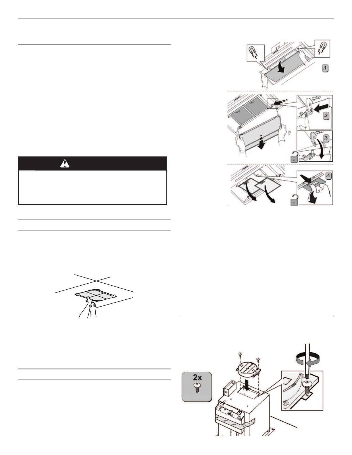
NOTE: For better
handling of the
hood, before
proceeding with
installation, remove
the perimeter
suction panel and
the grease lter,
as shown in gure,
steps 1-2-3-4.
3. For vented installations only: Using a jigsaw or keyhole saw,
cut a 6½" (16.5 cm) diameter hole for the vent duct.
Install In-Line Smart Kit - Optional
NOTE: Your hood can work with either an internal or an
in-line (external) blower motor system. An optional In-Line Smart
Kit (purchased separately) allows the blower motor that comes
with this hood to be installed in a location other than inside the
hood cavity.
CAUTION: To reduce the risk of re and electric shock, install this
hood only with the In-Line Smart Kit manufactured by Whirlpool,
W10692945.
For installation see the In-Line Smart Kit installation instructions.
See the “Assistance or Service” section to order.
Assemble and Install Hood
1. Install transition on top of hood (if removed for shipping) with
2 - 3.5 x 9.5 mm sheet metal screws.
Ø3.5x9.5 mm
Loading ...
Loading ...
Loading ...