Loading ...
Loading ...
Loading ...
-7
I
I
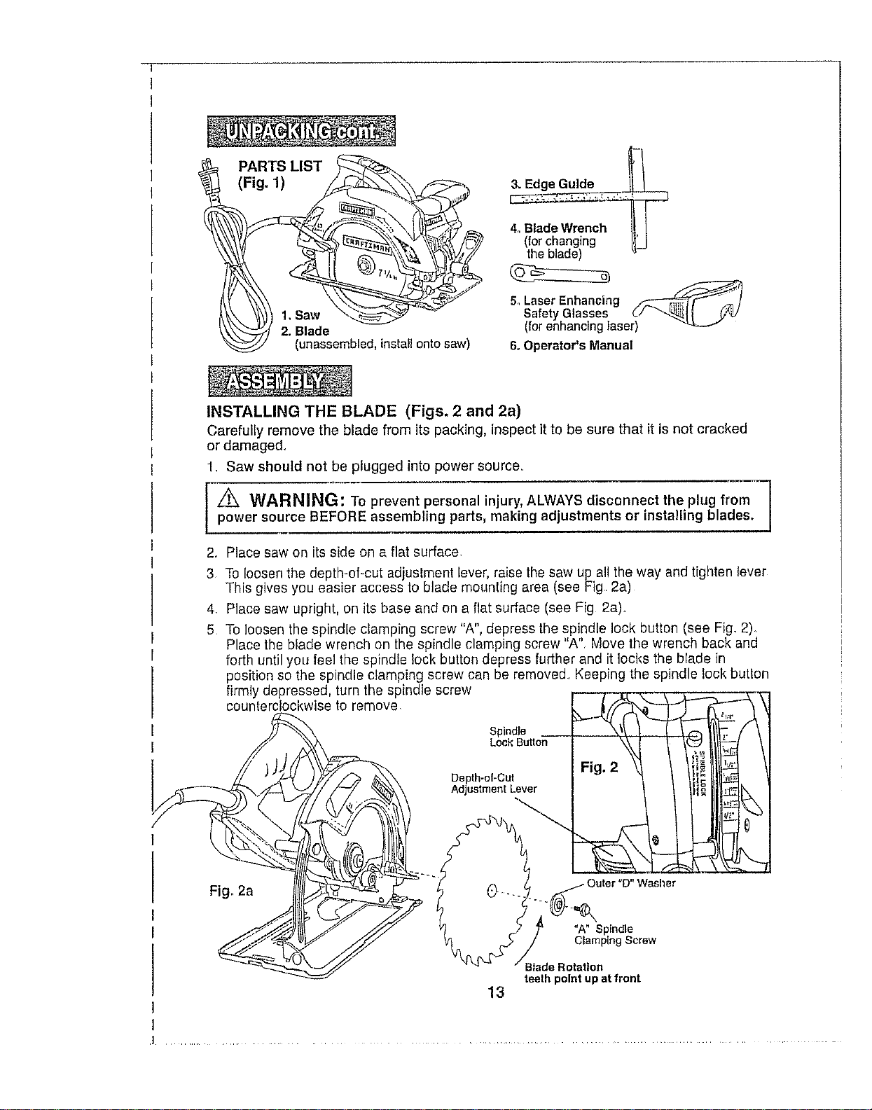
PARTS LIST
(Fig. 1)
(unassembled, install onto saw)
4. Blade Wrench I[ !
(forchanging I_J
the blade)
5_Laser Enhancing _/..,F /
Safety Glasses (-/ _11 .(7,U
(forenhancing laser) "_----"
6. Operator's Manual
INSTALLING THE BLADE (Figs. 2 and 2a)
Carefully remove the blade from its packing, inspect it to be sure that it is not cracked
or damage&
1, Saw should not be plugged into power source,
z_ WARNING: To prevent personal injury, ALWAYS disconnect the plug from
power source BEFORE assembling parts, making adjustments or installing blades.
2. Place saw on its side on a flat surface
3 To loosen the depth-of-cut ad ustment lever, raise the saw up all the way and tighten lever
This gives you easier access to blade mounting area (see Fig 2a)
4 Place saw upright, on its base and on a flat surface (see Fig 2a).
5 To loosen the spindle clamping screw "A", depress the spindle lock button (see Fig 2)_
Place the blade wrench on the spindle clamping screw "A", Move the wrench back and
forth until you feel the spindle lock button depress further and it locks the blade in
position so the spindle clamping screw can be removed Keeping the spindle lock button
firmly depressed, turn the spindle screw
counterclockwise to remove __j__ _ \J
Spindle __
Lock Button
Depth-oI-Cut
Adjustment Lever
Fig. 2a
)uter "D" Washer
=A" Spindle
Clamping Screw
Blade Rotation
teeth point up at front
13
Loading ...
Loading ...
Loading ...