Loading ...
Loading ...
Loading ...
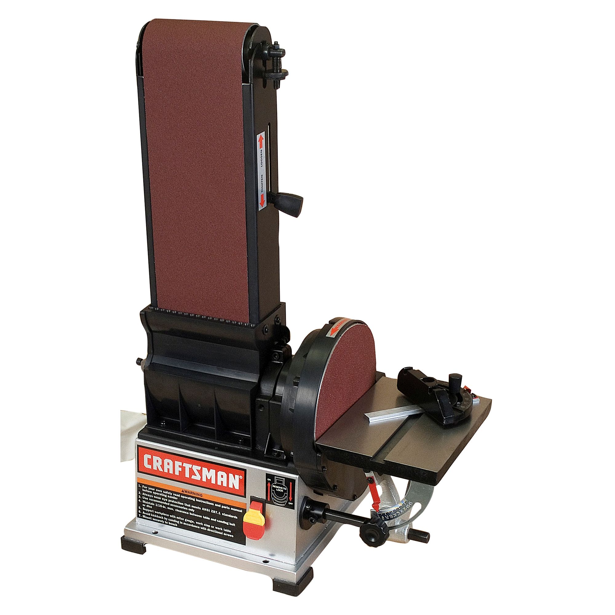
• Make sure abrasive belt always tracks properly. Correct
tracking gives optimum performance.
• After turning switch on, always allow belt and disc to come
up to full speed before sanding or grinding.
• Be sure disc turns counterclockwise. Abrasive belt must
travel downward.
• Avoid kickback by sanding in accordance with the direction-
al arrows.
• Keep your hands clear of abrasive belt, disc and all moving
parts.
• For optimum performance, do not stall motor or reduce
speed. Do not force the work into the abrasive.
• Always support workpiece with table or work stop when
sanding with belt and with table when sanding with disc.
• Never push a sharp corner of the workpiece rapidly against
the belt or disc. Abrasive backing may tear.
• Replace abrasives when they become loaded (glazed) or
frayed.
ON/OFF SWITCH
Refer to Figure 7.
The ON/OFF switch is located on the upper front right of the
cabinet. To turn the sander ON, pull the switch to the up
position. To turn the sander OFF, push the switch to the down
position.
The sander can be locked from unauthorized use by locking
the switch. To lock the switch:
= Turn the switch to OFF position and disconnect sander
from power source.
= Pull the key out. The switch cannot be turned on with the
key removed.
NOTE: Should the key be removed from the switch at the ON
position, the switch can be turned off but cannot be turned on
again.
= To replace key, slide key into the slot on switch until it snaps.
Figure 7 - Locking Switch in OFF Position
ADJUSTING BELT TRACKING
Refer to Figure 8.
° Quickly turn the switch ON and OFF to check the tracking.
Belt should ride centered on idler and drive drums. Adjust
tracking nut as needed to center belt on drums.
• If belt moves to the left, turn tracking nut to the right. If belt
moves to the right, turn tracking nut to the left.
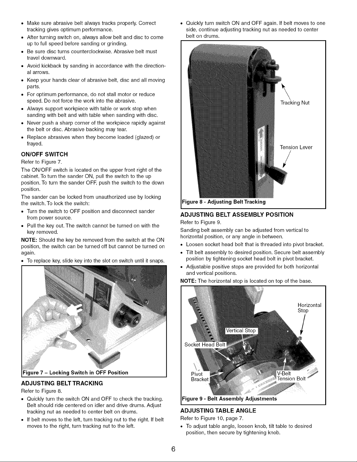
• Quickly turn switch ON and OFF again. If belt moves to one
side, continue adjusting tracking nut as needed to center
belt on drums.
\
Tracking Nut
Tension Lever
/
Figure 8 - Adjusting Belt Tracking
ADJUSTING BELT ASSEMBLY POSITION
Refer to Figure 9.
Sanding belt assembly can be adjusted from vertical to
horizontal position, or any angle in between.
• Loosen socket head bolt that is threaded into pivot bracket.
• Tilt belt assembly to desired position. Secure belt assembly
position by tightening socket head bolt in pivot bracket.
• Adjustable positive stops are provided for both horizontal
and vertical positions.
NOTE: The horizontal stop is located on top of the base.
Horizontal
Stop
Pivot
Figure 9 - Belt Assembly Adjustments
ADJUSTING TABLE ANGLE
Refer to Figure 10, page 7.
• To adjust table angle, loosen knob, tilt table to desired
position, then secure by tightening knob.
6
Loading ...
Loading ...
Loading ...