
Loading ...
Loading ...
Loading ...
B_it(B)
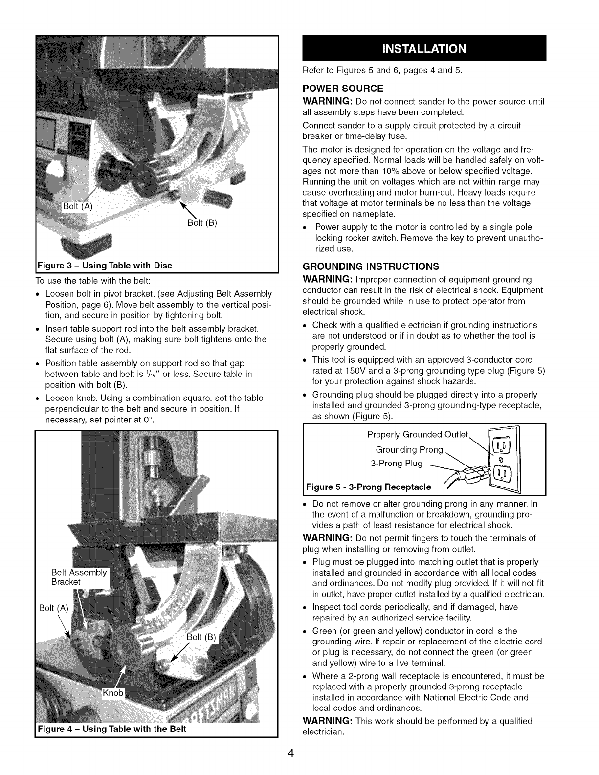
Figure 3 - Using Table with Disc
To use the table with the belt:
• Loosen bolt in pivot bracket. (see Adjusting Belt Assembly
Position, page 6). Move belt assembly to the vertical posi-
tion, and secure in position by tightening bolt.
• Insert table support rod into the belt assembly bracket.
Secure using bolt (A), making sure bolt tightens onto the
flat surface of the rod.
• Position table assembly on support rod so that gap
between table and belt is 1/16"or less. Secure table in
position with bolt (B).
• Loosen knob. Using a combination square, set the table
perpendicular to the belt and secure in position. If
necessary, set pointer at 0°.
(B)
Figure 4 - Using Table with the Belt
Refer to Figures 5 and 6, pages 4 and 5.
POWER SOURCE
WARNING: Do not connect sander to the power source until
all assembly steps have been completed.
Connect sander to a supply circuit protected by a circuit
breaker or time-delay fuse.
The motor is designed for operation on the voltage and fre-
quency specified. Normal loads will be handled safely on volt-
ages not more than 10% above or below specified voltage.
Running the unit on voltages which are not within range may
cause overheating and motor burn-out. Heavy loads require
that voltage at motor terminals be no less than the voltage
specified on nameplate.
• Power supply to the motor is controlled by a single pole
locking rocker switch. Remove the key to prevent unautho-
rized use.
GROUNDING INSTRUCTIONS
WARNING: Improper connection of equipment grounding
conductor can result in the risk of electrical shock. Equipment
should be grounded while in use to protect operator from
electrical shock.
• Check with a qualified electrician if grounding instructions
are not understood or if in doubt as to whether the tool is
properly grounded.
• This tool is equipped with an approved 3-conductor cord
rated at 150V and a 3-prong grounding type plug (Figure 5)
for your protection against shock hazards.
• Grounding plug should be plugged directly into a properly
installed and grounded 3-prong grounding-type receptacle,
as shown (Figure 5).
Grounded Outlet
Properly
Grounding Prong
3-Prong Plug _'__
Figure 5 - 3-Prong Receptacle
° Do not remove or alter grounding prong in any manner. In
the event of a malfunction or breakdown, grounding pro-
vides a path of least resistance for electrical shock.
WARNING: Do not permit fingers to touch the terminals of
plug when installing or removing from outlet.
• Plug must be plugged into matching outlet that is properly
installed and grounded in accordance with all local codes
and ordinances. Do not modify plug provided. If it will not fit
in outlet, have proper outlet installed by a qualified electrician.
• Inspect tool cords periodically, and if damaged, have
repaired by an authorized service facility.
• Green (or green and yellow) conductor in cord is the
grounding wire. If repair or replacement of the electric cord
or plug is necessary, do not connect the green (or green
and yellow) wire to a live terminal.
• Where a 2-prong wall receptacle is encountered, it must be
replaced with a properly grounded 3-prong receptacle
installed in accordance with National Electric Code and
local codes and ordinances.
WARNING: This work should be performed by a qualified
electrician.
4
Loading ...
Loading ...
Loading ...