Loading ...
Loading ...
Loading ...
A
Y
PRIMARY
MANDREL
MOWER DRIVE
BELT
FRONT
SUSPENSION
BRACKET
FIGURE 9
GAUGE
WHEEL
\
GAUGE/
WHEEL
BAR
BRACKET
_CLEVIS
FIGURE 10/I PIN
CLUTCH
PULLEY
MOWER
DRIVE
BELT
LEVER
TENSION
PULLEY
IDLER
_GURE 11
PULL FORWARD
TO LOOSEN BELT
FOR EASIER BELT
INSTALLATION
IDLER BRACKET
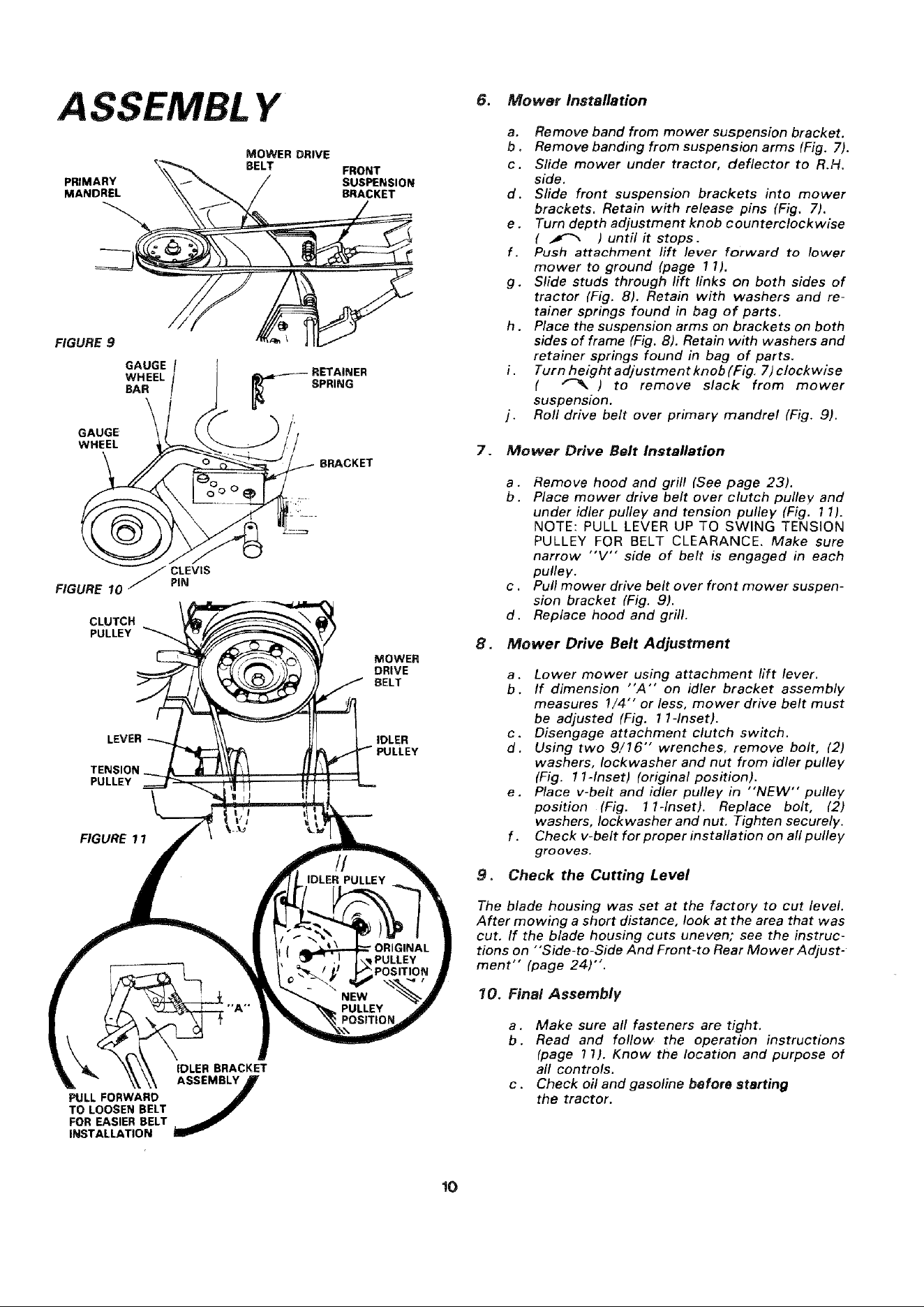
6. Mower Installation
a. Remove band from mower suspension bracket.
b . Remove banding from suspension arms (Fig. 7),
c. Slide mower under tractor, deflector to R.H.
side.
d. Slide front suspension brackets into mower
brackets. Retain with release pins (Fig. 7).
e. Turn depth adjustment knob counterclockwise
( _ ) until it stops.
f. Push attachment lift lever forward to lower
mower to ground (page 11),
g. Slide studs through lift links on both sides of
tractor (Fig. 8). Retain with washers and re-
tainer springs found in bag of parts.
h. Place the suspension arms on brackets on both
sides of frame (Fig. 8). Retain with washers and
retainer springs found in bag of parts,
Turn height adjustment knob (Fig. 7) clockwise
( _ ) to remove slack from mower
suspension.
I. Roll drive belt over primary mandrel (Fig. 9).
7. Mower Drive Belt Installation
a. Remove hood and grill (See page 23).
b. Place mower drive belt over clutch pulley, and
under idler pulley and tension pulley (Fig, 11).
NOTE: PULL LEVER UP TO SWING TENSION
PULLEY FOR BELT CLEARANCE. Make sure
narrow "'V'" side of belt is engaged in each
pulley.
c . Putl mower drive belt over front mower suspen-
sion bracket (Fig. 9).
d. Replace hood and grill.
8. Mower Drive Belt Adjustment
a. Lower mower using attachment lift lever.
b. If dimension "A'" on idler bracket assembly
measures !/4"" or less, mower drive belt must
be adjusted (Fig. 1I-Inset).
c. Disengage attachment clutch switch.
d. Using two 9/16" wrenches, remove bolt, (2)
washers, Iockwasher and nut from idler pulley
(Fig. 1l-Inset) (original position).
e. Place v-belt and idler pulley in "'NEW" pulley
position (Fig. 1I-Inset). Replace bolt, (2)
washers, Iockwasher and nut, Tighten securely.
f . Check v-belt for proper installation on all pulley
grooves.
9. Check the Cutting Level
The blade housing was set at the factory to cut level.
After mowing a short distance, look at the area that was
cut. If the blade housing cuts uneven; see the instruc-
tions on "'Side-to-Side And Front-to Rear Mower Adjust-
ment" (page 24)".
10. Final Assembly
a. Make sure all fasteners are tight.
b. Read and follow the operation instructions
(page 1 !). Know the location and purpose of
all controls.
c. Check oil and gasoline before starting
the tractor.
!O
Loading ...
Loading ...
Loading ...