
CAUTION
BEFORE SERVICING THE UNIT,
READ THE SAFETY PRECAUTIONS IN THIS MANUAL.
REFRIGERATOR
SERVICE MANUAL
R
Model #s:
795.77562600
795.77569600
795.77564600
795.77563600
795.77572600
795.77579600
795.77573600
P/No. 3828JL8091A (Last Revision: March. 28. 2008)

Safety Precautions
1. Specification.........................................................................................................................................................................
2. Parts Identification...............................................................................................................................................................
3. Operation ..............................................................................................................................................................................
3-1. Explanation of Each Function .........................................................................................................................................
3-2. Ice Maker Function..........................................................................................................................................................
4. Wiring Diagram.....................................................................................................................................................................
5. Adjustment............................................................................................................................................................................
5-1. Compressor.....................................................................................................................................................................
5-2. Positive Temperature Coefficient (PTC) – Starter...........................................................................................................
5-3. Over Load Protector (OLP).............................................................................................................................................
5-4. Remove the cover Positive Temperature Coefficient (PTC)
6. Troubleshooting...................................................................................................................................................................
6-1. Error Mode Summary......................................................................................................................................................
6-2. Troubleshooting With Error .............................................................................................................................................
6-3. Troubleshooting Else ......................................................................................................................................................
7. Component Testing Information.........................................................................................................................................
7-1. Defrost Controller Assembly ...........................................................................................................................................
7-2. Sheath Heater.................................................................................................................................................................
7-3. Door Heater Assembly....................................................................................................................................................
7-4. Switch (F, R)....................................................................................................................................................................
7-5. Solenoid..........................................................................................................................................................................
7-6. AC Motor Assembly ........................................................................................................................................................
7-7. Damper ...........................................................................................................................................................................
7-8. Lamp Socket...................................................................................................................................................................
8. Disassembly Instructions....................................................................................................................................................
9. PCB Assembly......................................................................................................................................................................
10. Exploded View....................................................................................................................................................................
CONTENTS
- 2 -
Please read the following instructions before servicing your
refrigerator.
1. Unplug the power before handling any elctrical
componets.
2. Check the rated current, voltage, and capacity.
3. Take caution not to get water near any electrical
components.
4. Use exact replacement parts.
5. Remove any objects from the top prior to tilting the
product.
SAFETY PRECAUTIONS
1. SPECIFICATIONS
- 3 -
1-1 DISCONNECT POWER CORD BEFORE
SERVICING
IMPORTANT – RECONNECT ALL
GROUNDING DEVICES
All parts of this appliance capable of conducting electrical
current are grounded. If grounding wires, screws, straps,
clips, nuts or washers used to complete a path to ground
are removed for service, they must be returned to their
original position and properly fastened.
1-2 IMPORTANT NOTICE
This information is intended for use by individuals
possessing adequate backgrounds of electrical, electronic
and mechanical experience. Any attempt to repair a major
appliance may result in personal injury and property
damage. The manufacturer or seller cannot be responsible
for the interpretation of this information, nor can it assume
any liability in connection with its use.
1-3 ELECTRICAL SPECIFICATIONS
Temperature Control (F )...-6°F to +8°F
Defrost Control...................Total Comp Running Time 7 hrs
Defrost Thermostat.......................................................46°F
Electrical Rating : 115VAC, 60Hz.................................1-5 A
Maximum Current Leakage.......................................0.5 mA
Maximum Ground Path Resistance....................0.14 Ohms
Energy Consumption .....25 cu.ft. 579 kWh/yr (Energy Star)
1-4 NO LOAD PERFORMANCE
CONTROL POSITION: MID/MID
And Ambient of: ..................70°F..................................90°F
Fresh Food, °F....................33°F to 41°F.........33°F to 41°F
Frozen Food, °F..................-4°F to +4°F..........-4°F to +4°F
Percent Running Time........35%-45%.................50°F-70°F
1-5 REFRIGERATION SYSTEM
Minimum Compressor Capacity Vacuum ............... 21 MIN.
Minimum Equalized Pressure
@ 70°F ....................................................... 49 PSIG
@ 90°F ....................................................... 56 PSIG
Refrigerant R134a ................................................. 4.41 oz.
Compressor ..................................................... 956 BTU/hr
1-6 INSTALLATION
Clearance must be provided at top, sides and rear of the
refrigerator for air circulation.
AT TOP ......................................................................... 2 in
AT SIDES ...................................................................... 1 in
AT REAR ...................................................................... 1 in
1-7 REPLACEMENT PARTS
Relay..............................................................6748C-0004D
Overload........................................................6750C-0004R
Defrost Thermostat........................................6615JB2005H
Defrost Heater...............................................5300JK1005D
Evaporator Fan Motor....................................4681JK1004E
Capacitor (Running) .....................................0CZZJB2014B
*0CZZJB2012H
*0CZZJB2012K
Compressor (Hi-Side)...................................TCA31748001
Evaporator (Lo-Side)......................................5421JJ1007A
Condenser......................................................5403JJ1004B
Dryer..............................................................5851JA2002P
Condenser Fan Motor ...................................4681JB1029D
Temperature Control ..............................3551JA1132L(SW)
3551JA1132M(ST)
3551JA1132N(WB)
3551JA1132P(BI)
Main Control....................................................EBR3491102
Ice Fan Motor ................................................4681JB1029E
*OPTIONAL
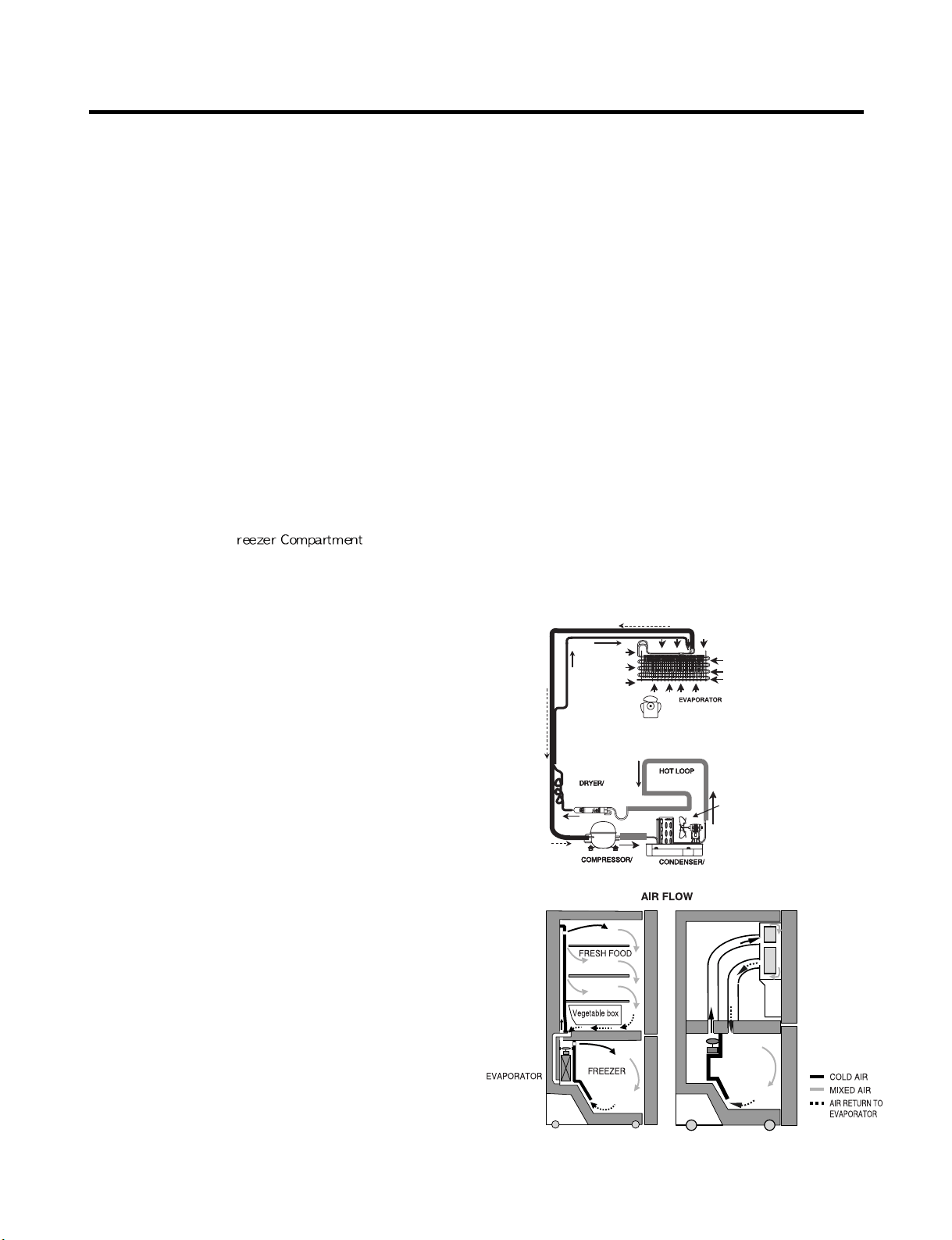
1-8 AIR FLOW / CIRCULATION D’AIR
EVAPORTOR FAN MOTOR
CONDENSER FAN MOTOR
ICE
ROOM
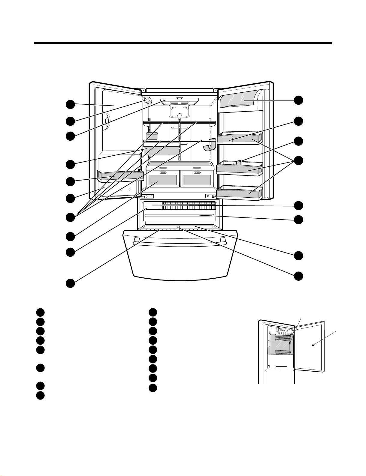
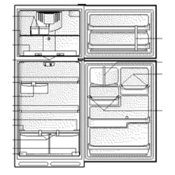
2. PARTS IDENTIFICATION
- 4 -
A
B
F
N
M
E
L
H
G
C
P
C
Q
O
D
I
K
J
Refrigerator Light
Filter (Inside)
Modular Door Bins
Refrigerator Shelves
Supra Fresh Crisper with
Tilt-Out Compartment
Ice Room
(ICEMAKER and ICE BIN)
Pull out Drawer
Turbo Motor
Tilt-Out Door Basket
Durabase
Divider
Ice Bin
Water Tank Cover
Snack Pan
Egg Box
Dairy Bin
Bottle Holder
A
B
C
D
E
F
G
H
I
J
K
L
M
N
O
P
Q
Ice Bank
Ice Door
3. OPERATION
- 5 -
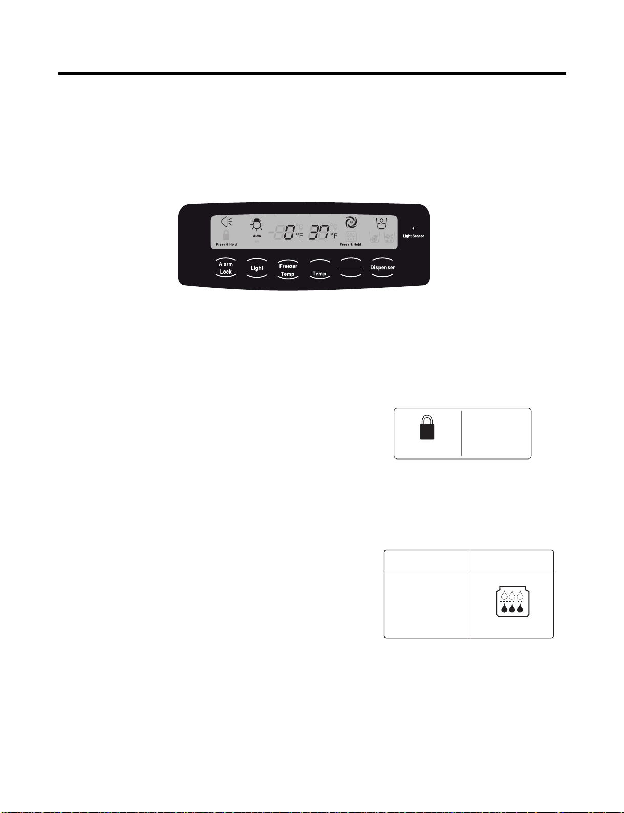
3-1. Explanation Of Each Function
1. Function
(1) When the appliance is plugged in, it is set to 37 °F for the refrigerator and 0 °F for the freezer.
You can adjust the refrigerator and the freezer control temperature by pressing the ADJUST button.
(2) When the power is initially applied or restored after a power failure, maintains its previously set temperature.
.
2 How to Toggle the Display between °F and °C
(1) The initial setting is °F and the display temperature mode can be changed from °F to °∆C or °∆C to °∆F by pressing and
holding the FRZ TEMP and the REF TEMP keys at the same time for over 5 seconds.
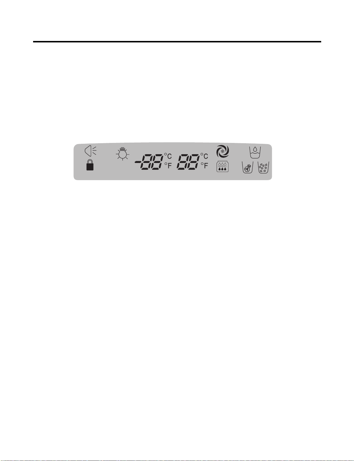
3. Lock function (dispenser and display button lock)
(1) When the refrigerator is first turned on, the buttons are not
locked. The display panel shows the padlock unlocked icon.
(2) To lock the display, the dispenser, and the control panel, press
and hold the LOCK button for 3 seconds. The locked pad lock
icon is displayed.
(3) The LOCK button is the only control feature that remains
active in the locked state. The buzzer sound, other control
buttons, and the dispenser are deactivated.
(4) To release from the locked state, press and hold the LOCK
button again for 3 seconds.
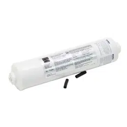
4. Filter condition display function
(1) There is a replacement indicator icon for the filter
cartridge on the dispenser.
(2)The water filter should be replaced approximately
every six months.
(3) The water filter icon will turn on every six months
to remind you to replace.
(4) After replacing the filter, press and hold the lock
button more than 3 seconds.
This will turn off the reminder icon and reset the timer.
Refrigerator
Ultra lce
Filter Reset
Ex) In selecting
"LOCK"
Ex) In selecting
"LOCK" again
Press & Hold Press & Hold
In initial Power On
/ Filter RESET
Replace indicator
light on
Classification
Filter Status
Display
Press & Hold Press & Hold
- 6 -
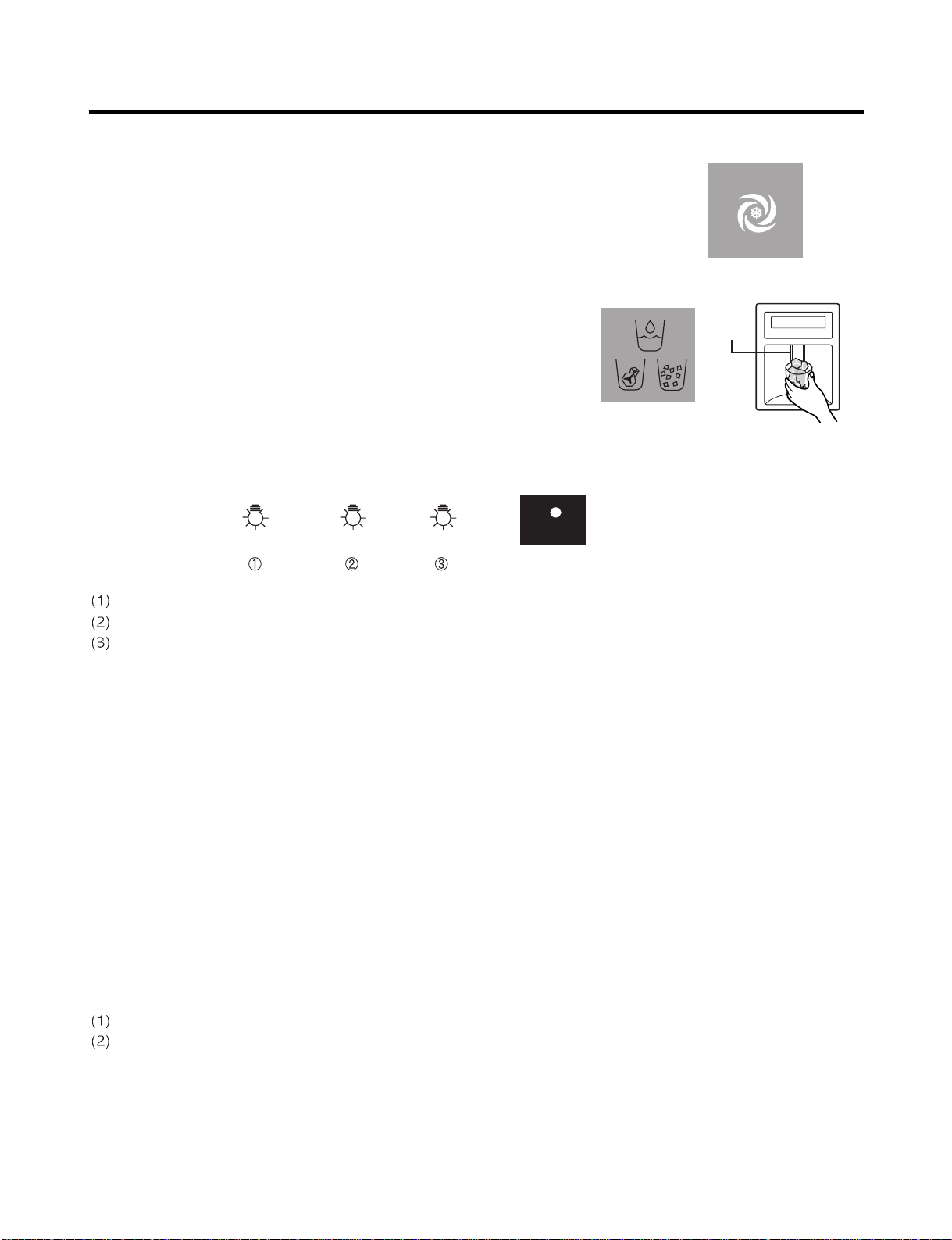
5. Ice Plus Selection
Please select this function for quick freezing.
(1) The ICE PLUS option starts counting its 24-hours period every time the
button is pressed.
(2) The ICE PLUS function automatically turns off after twenty-four hours pass.
6. Dispenser Use Selection
You can select water or ice.
∗ Select water, crushed ice, or ice cubes by cycling through the
selections when pressing the DISPENSER button,
∗ Hold your cup in the dispenser for a few seconds after dispensing
ice or water to allow the last pieces of ice or drops of water to fall
into the cup.
7. Dispenser Light
Whenever the light button is pressed, the display changes as shown below.
Normal status: When dispenser is operated, DISPENSER LIGHT is ON.
AUTO status: Detecting the lighting of room by LIGHT SENSOR, DISPENSER LIGHT is on and off automatically.
ON status: DISPENSER LIGHT is on continuously.
8. Control Of Freezer Fan Motor
(1) Freezer fan motor has high and standard speeds.
(2) High speed is used at power-up, for Ice Plus, and when refrigerator is overloaded.
Standard speeds is used for general purposes.
(3) To improve cooling speed, the RPM of the freezer fan motor changes from normal speed to high.
(4) High speed (2700RPM) : Initial power on or load corresponding operation, Ice Plus
Normal speed (2400RPM) : General working conditions.
(5) Fan motor stops when a refrigerator or freezer door opens.
9. Cooling Fan Motor
(1) The cooling fan is switched ON and OFF in conjunction with the compressor.
(2) The cooling fan runs at a single speed.
(3) The Failure sensing method is the same as in the fan motor of the freezing fan motor(refer to failure diagnosis function
table for failure display).
10. Icing Fan
The Icing Fan is controlled by the the sensor on the top of the ice room.
The Failure sensing method is the same as in the fan motor of the freezer
(refer to failure diagnosis function table for failure display)
Pressing
Switch
Auto Auto
on
Light Sensor
- 7 -
11. Ice Plus
(1) The purpose of this function is to intensify the cooling speed of freezer and to increase the amount of ice.
(2) Whenever selection switch is pressed, selection/release, the LED will turn ON or OFF.
(3) If there is a power outage and the refrigerator is powered on again, Ice Plus will be canceled.
(4) To activate this function, press the Ice Plus key and the LED will turn ON. This function will remain activated for 24 hours.
The first three hours the compressor and Freezer Fan will be ON. The next 21 hours the freezer will be controlled at the
lowest temperature. After 24 hours or if the Ice Plus key is pressed again, the freezer will return to its previous
temperature.
(5) During the first 3 hours:
• Compressor and freezer fan (HIGH RPM) run continuously.
• If a defrost cycle begins during the first 90 minutes of Ice Plus, the Ice Plus cycle will complete its cycle after defrosting
has ended.
If the defrost cycle begins when Ice Plus has run for more than 90 minutes, Ice Plus will run for two hours after the
defrost is completed.
• If Ice Plus is pressed during defrost, Ice Plus LED is on but this function will start seven minutes after defrost is
completed and it shall operate for three hours.
• If Ice Plus is selected within seven minutes after compressor has stopped, the compressor (compressor delays seven
minutes) shall start after the balance of the delay time.
• The fan motor in the freezer compartment runs at high speed during Ice Plus.
(6) For the rest of the 21 hours, the freezer will be controlled at the lowest temperature.
12. Freezer and Refrigerator Lamp Auto Off
(1) To avoid heat damage caused by the lamp, it is turned off automatically when the refrigerator door is open for more than
7 minutes.
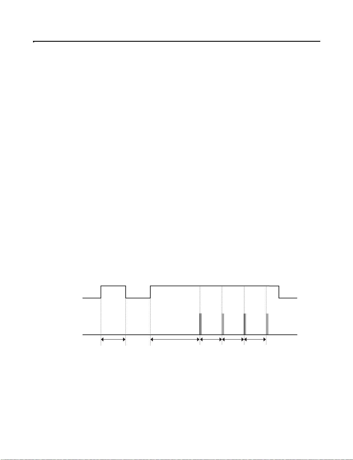
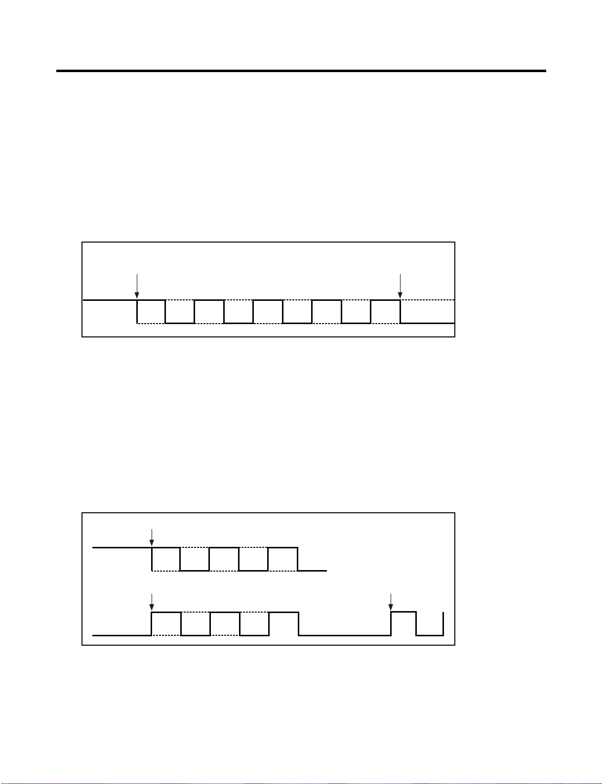
13. Alarm for Open Door
(1) This feature sounds a buzzer when the freezer or refrigerator door is not closed within 1 minute after it is opened.
(2 One minute after the door is opened, the buzzer sounds three times each for one half seconds. These tones repeat every
30 seconds.
(3) The alarm is cancelled when the freezer or the refrigerator is closed.
Closed Open Closed Open
3 Times 3 Times 3 Times 3 Times
Closed
Within 1 min. 1 min.
30 sec 30 sec 30 sec
Freezer Door
or Refrigerator
Door
Buzzer
- 8 -
14. Defrosting (removing frost)
(1) Defrosting starts each time the COMPRESSOR running time reaches 7 hours.
(2) For initial power on or for restoring power, defrosting starts when the compressor running time reaches 4 hours.
(3) Defrosting stops if the sensor temperature reaches 46.4°F (8°C) or more. If the sensor doesn’t reach 46.4°F (8°C) in
2 hours, the defrost mode is malfunctioning. (Refer to the defect diagnosis function, 15.)
(4) Defrosting won’t function if its sensor is defective (wires are cut or short circuited)
15. Defect Diagnosis Function
(1) Automatic diagnosis makes servicing the refrigerator easy.
(2) When a defect occurs, the buttons will not operate; but the tones will sound.
(3) When the defect CODE removes the sign, it returns to normal operation (RESET).
(4 The defect CODE shows on the Refrigerator and Freezer Display.
✽ LED check function: Press Ice Plus and Freezer buttons for a second, display LED graphics on.
If releasing the button, the LED graphic displays the previous status.
Press & Hold Press & Hold
Auto
on
- 9 -
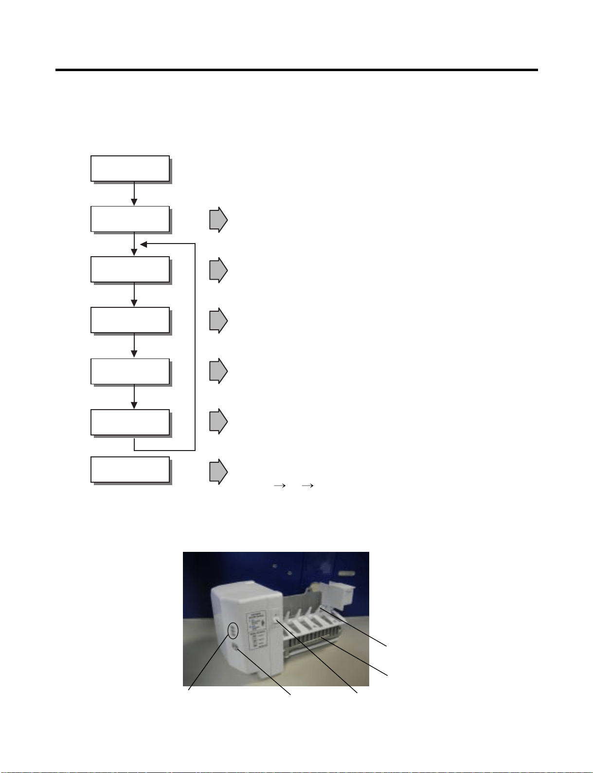
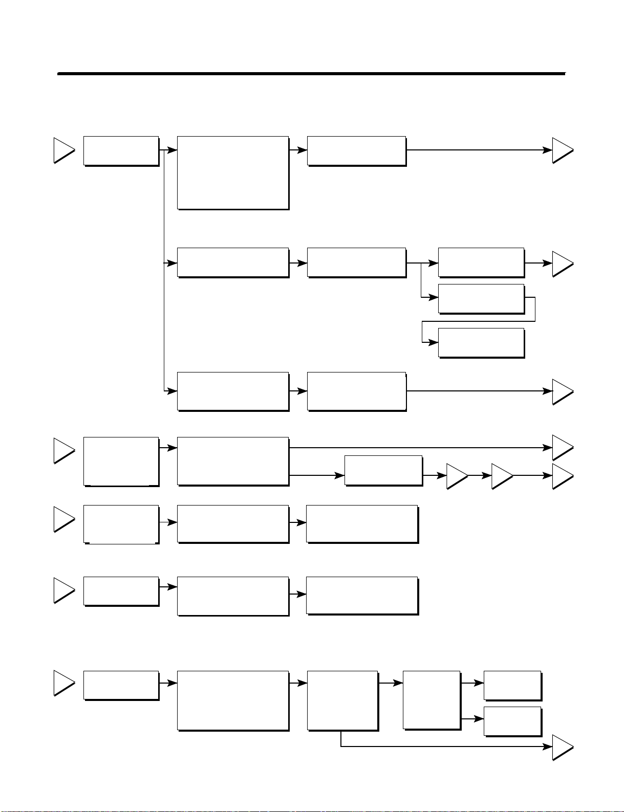
3-2. Ice Maker Function
1. Operation Principle of icemaker
(1) Turning the Icemaker stop switch off (O) stops the ice making function.
(2) Setting the Icemaker switch to OFF and then turning it back on will reset the icemaker control.
• Adjusts EJECTOR to Start Position with power on.
Power On
Start Position
Icemaking
Mode
Harvest
Mode
Fill
Park Position
Test Mode
• Waits until water becomes ICE after starting the
icemaking operation.
• Runs MOTOR to drop ice from the tray into the ICE BIN.
(During harvest mode, check if the ice bin is full.)
• Performs Ice Making Mode after supplying water by operating
the SOLENOID in ICE VALVE.
• To operate LINE and SERVICE, press and hold the Cube Size button
for 3 seconds. The icemaker will run through 3 stages:
Harvest Fill Icemaking.
• Reaches Start Position
Cube Size
Indicator Light
Cube Size
Selection Button
Power
Switch
Automatic
Shut off Arm
EJECTOR
- 10 -
2. Icemaking Mode
(1) Icemaking refers to the freezing of supplied water in the ice tray. Complete freezing is assured by
measuring the temperature of the tray with Icemaking SENSOR.
(2) Icemaking starts after completion of the water fill operation.
(3) The icemaking function is completed when the sensor reaches 1 9 °∆F (-7 °∆C), 55 minutes after starting.
NOTE : After the icemaker power is ON, the icemaker heater will be on for test for 6 seconds.
3. Harvest Mode
(1) Harvest (Ice removing) refers to the operation of dropping cubes into the ice bin from the tray when
icemaking has completed.
(2) Harvest mode:
• The Heater is ON for 30 seconds, then the motor starts.
• The feeler arm senses the quantity of ice in the ice storage bin while rotating with the EJECTOR.
A. Ice storage bin is full : The EJECTOR stops (heater off).
B. Ice storage bin is not full : The EJECTOR rotates twice to open for ice.
* If the EJECTOR does not rotate once within 5 minutes in B mode, separate heater control mode starts operating to
prevent the EJECTOR from being constrained. (It is recommended that the user open for ice to return to normal mode.)
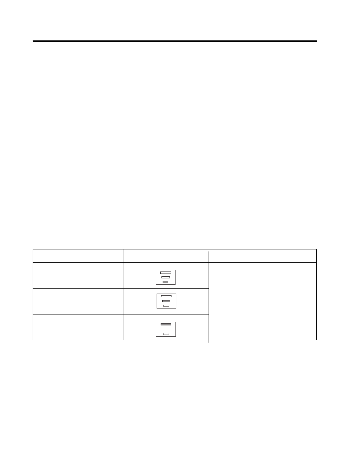
4. Fill/Park Position
(1) Once a normal harvest mode has been completed, the water solenoid will be activated.
(2) The amount of water is adjusted by pressing the fill key repeatedly. This changes the time allowed for fill as illustrated in
the table below.
Water supply amount TABLE
STAGE TIME TO SUPPLY INDICATIONS REMARKS
1
2
3
5 sec.
5.5 sec.
(FIRST STAGE)
6 sec.
The water amount will vary depending
on the water control switch setting as
well as the water pressure of the
connected water line.
- 11 -
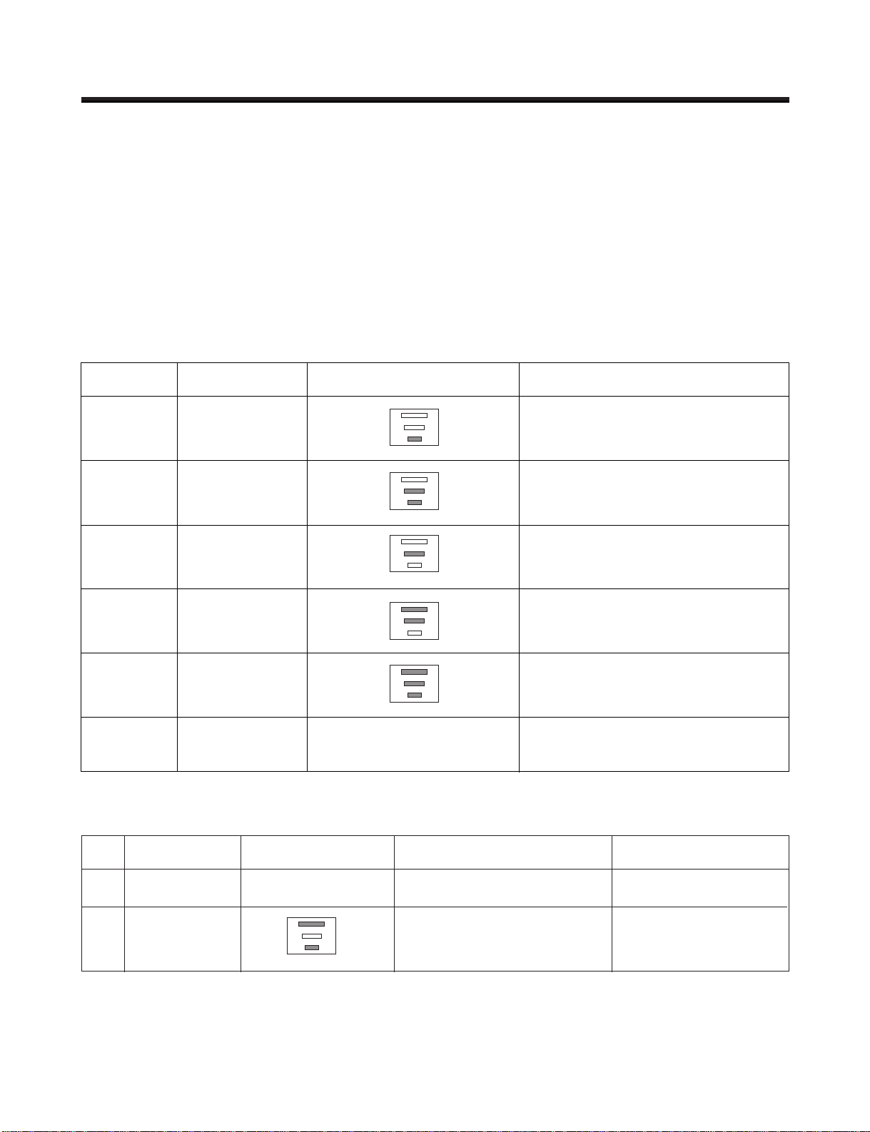
5. Function TEST
(1) This is a forced operation for test, service, cleaning, etc. It is operated by pressing and holding the cube size button for 3
seconds.
(2) The test works only in the Icemaking Mode. It cannot be entered from the Harvest or Fill mode.
(3) Caution! Caution! Caution! Caution! If the test is performed before water in the icemaker is frozen, the ejector will pass
through the water. When the fill mode begins (Stage 4), unless the water supply has been shut off, added water will
overflow into the ice bin. If the control doesn ’ t
(4) After water is supplied, the normal CYCLE is followed: icemaking → Harvest → Park Position → Fill.
(5) Five seconds after Stage 5 is completed, the icemaker returns to MICOM control. The time needed to supply water
resets to the
Diagnosis TABLE
6. Error codes shown on the icemaker water supply control panel
STAGE ITEMS INDICATOR REMARKS
1
2
3
4
5
6
HEATER
MOTOR
HALL IC I
HALL IC II
VALVE
Reset
Five seconds after the heater starts, it
will go off if the temperature by
sensor is higher than 10°C
Five seconds after the heater starts, you
can confirm that the motor is moving.
Check whether ice bin is full. If the ice bin
if full, the motor and heater are off, but on
standby until the ice bin is empty.
You can confirm HALL IC detection of start
position.
Two seconds after the detection of start
position, you can confirm that the valve is on.
Five seconds after the fifth stage is
completed, the icemaker resets to initial
status.
Return to Status prior to
TEST MODE
NO DIVISION INDICATOR CONTENTS REMARKS
1
2
Normal
Icemaking
sensor
malfunction
Mark time to
supply
None
Open or short-circuited wire
Display switch
operates properly
Make sure that the wire
on each sensor is
connected.
- 12 -
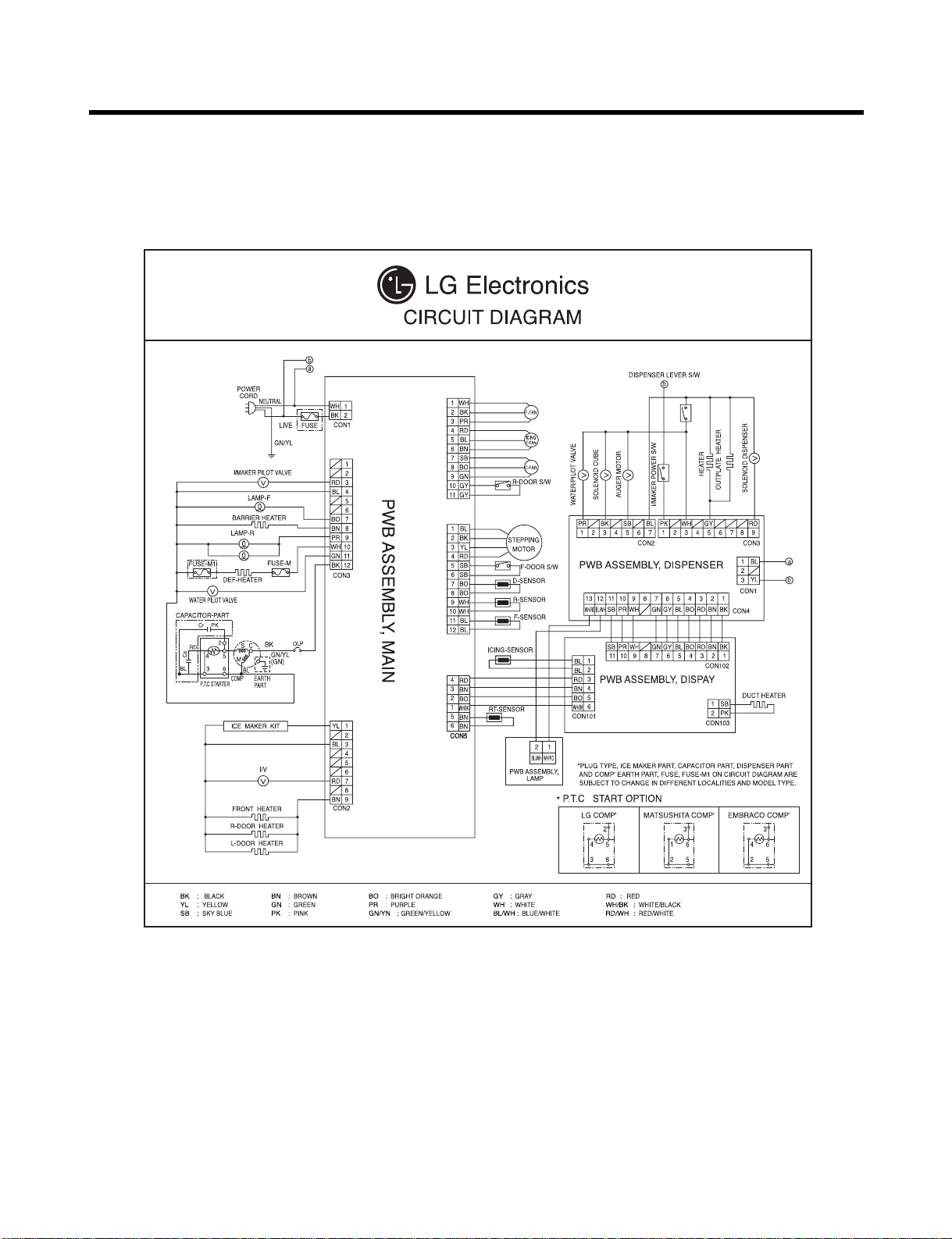
4. WIRING DIAGRAM

5-1. Compressor
1. Role
The compressor intakes low temperature and low pressure gas from the evaporator of the refrigerator and
compresses this gas to high-temperature and high-pressure gas. It then delivers the gas to the condenser.
2. Composition
The compressor includes overload protection. The PTC starter and OLP (overload protector) are attached to
the outside of the compressor. Since the compressor is manufactured to tolerances of 1 micron and is
hermetically sealed in a dust and moisture-free environment, use extreme caution when performing repairs.
3. Note for usage
(1) Be careful not to allow over-voltage and over-current.
(2) If compressor is dropped or handled carelessly, poor operation and noise may result.
(3) Use proper electric components appropriate to the particular compressor in your product.
(4) Keep the compressor dry. If the Compressor gets wet (in the rain or a damp environment) and rust forms
in the pin of the Hermetic Terminal, poor operation and contact may result.
(5) When replacing the compressor, be careful that dust, humidity, and soldering flux don’t contaminate the
inside of the compressor. Dust, humidity, and solder flux may contaminate the cylinder and may cause
noise, improper operation, or even lock up.
5. ADJUSTMENT
- 13 -
4. diagnosis
- 14 -
1
2
3
4
5
2
5
5
3
5
1
43
YES
NO
YES
The range of resistance is between 1~50Ω(ok)
Open or short
YES YES
NO
NO
Power Source.
No Voltage.
(Rated Voltage
±10%)?
Replace OLP.
Reconnect.
Reference 5-2
Reference 5-3
Did
compressor
start?
Compressor
is OK
Replace the
compressor
Check connection
condition.
OLP disconnected?
Advise customer that
power supply needs to be
checked by an electrician.
Replace
Compressor.
Supply
voltage rating
with ±10%.
Applied voltage isn't
in acceptable range.
(115V ±10%)
Remove PTC-Starter
from Compressor and
measure voltage
between Terminal C of
Compressor and
Terminal 5 or 6 of PTC.
Check resistance
between M-C, S-C and
M-S in Motor
Compressor.
Check resistance of
two terminals in
PTC-Starter.
Check resistance of two
terminals in OLP.
Check the power supply
under load.
(Compressor attempting
to re-start after being off
for 5 minutes).
Check
resistance of
Motor
Compressor.
Check
resistance of
PTC-Starter.
Check OLP.
Check
starting state.
- 15 -
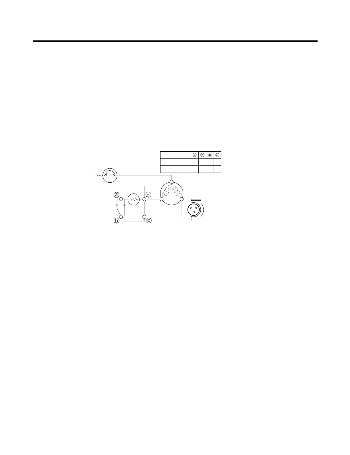
5-2. Positive Temperature Coefficient (PTC) – Starter
1. Composition
(1) PTC (Positive Temperature Coefficient) is a no-contact semiconductor starting device which uses ceramic
material consisting of BaTiO3.
(2) The higher the temperature is, the higher the resistance value. These features are used as a starting
device for the motor.
2. Role
(1) The PTC is attached to the sealed compressor and is used for starting the compressor motor.
(2) The compressor is a single-phase induction motor. For starting operation, the PTC allows current flow to
both the start winding and main winding.
3. PTC – Applied circuit diagram
● Starting Method for the Motor
4. Motor restarting and PTC cooling
(1) It requires approximately 5 minutes for the pressure to equalize before the compressor can restart.
(2) The PTC device generates heat during operation. Therefore, it must be allowed to cool before the
compressor can restart.
5. Relation of PTC – Starter and OLP
(1) If the compressor attempts to restart before the PTC device is cooled, the PTC device will allow current to
flow only to the main winding.
(2) The OLP will open because of the over current condition. This same process will continue (3 to 5 times)
when the compressor attempts to restart until the PTC device has cooled. The correct OLP must be
properly attached to prevent damage to the compressor. Parts may appear physically identical but could
have different electrical ratings. Replace parts by part number and model number. Use only approved
substitute parts.
6. Note for Using the PTC-Starter
(1) Be careful not to allow over-voltage and over-current.
(2) Do not drop or handle carelessly.
(3) Keep away from any liquid. If liquid such as oil or water enters the PTC, the materials may fail due to
breakdown of their insulating capabilities.
(4) If the exterior of the PTC is damaged, the resistance value may be altered. This can cause damage to the
compressor and result in a no-start or hard-to-start condition.
(5) Always use the PTC designed for the compressor and make sure it is properly attached to the compressor.
Parts may appear physically identical but could have different electrical ratings. Replace parts by part
number and model number. Use only approved substitute parts.
PTC STARTER
SEALED
TERMINAL
COMPRESSOR
MOTOR
C
M
S
M
S
N
L1
OVERLOAD PROTECTOR
Resistance Starter Capacitor Running
PTC
2
LFX21960**
LFX25960**
3 2 5 6
2 3 6 5
- 16 -
5-3. Over Load Protector (OLP)
1. Define
(1) The OLP (OVERLOAD PROTECTOR) is attached to the Compressor and protects the motor by opening the
circuit to the motor if the temperature rises and activating the bimetal spring in the OLP.
(2) When high current flows to the compressor motor, the Bimetal works by heating the heater inside the OLP,
and the OLP protects the Motor by cutting off the current flowing to the Compressor Motor.
2. Role
(1) The OLP is attached to the sealed compressor
used for the refrigerator. It prevents the motor
coil from being started in the compressor.
(2) For normal operation of the OLP, do not turn
the adjustment screw of the OLP in any way.
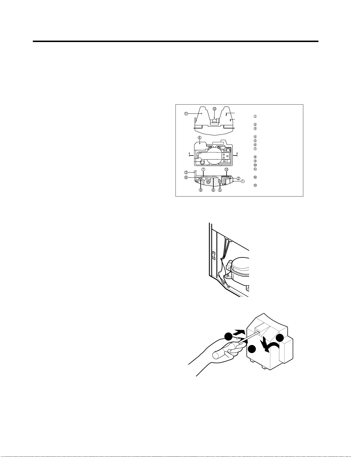
5-4. Remove the cover Positive Temperature Coefficient (PTC)
(1) Remove the cover of the mechanical area.
(2) Disconnect the two clamps holding
the compressor in place.
(3) Loosen two screws on compressor base.
(4) Use a screwdriver to pry off the cover.
(5) Assembly is the reverse order of disassembly.
Part
Customer part
number
Lot code/
date code
330 FBYY -S1 BOX98
12345678
Physical
termination
part number
Electrical
characteristics
part number
No. Name
Base, phenolic
(UL 94 V-0 rated)
Movable arm support, plated steel
Stationary contact support,
plated steel
Heater support, plated steel
Heater, resistance alloy
Disc, thermostatic alloy
Movable arm, spring temper
copper alloy
Contact, movable, silver on copper
Contact, stationary, silver on copper
Slug, plated steel
Cover, polyester
(UL 94 V -0 rated)
Pin connector, plated copper alloy
(To engage 2.33/2.66 mm dia. pin)
Quick-connect terminal, brass,
conforms to UL 310, MEMA
DC-2, DIN 46344
(OVERLOAD PROTECTOR cross section)
2
3
1
- 17 -
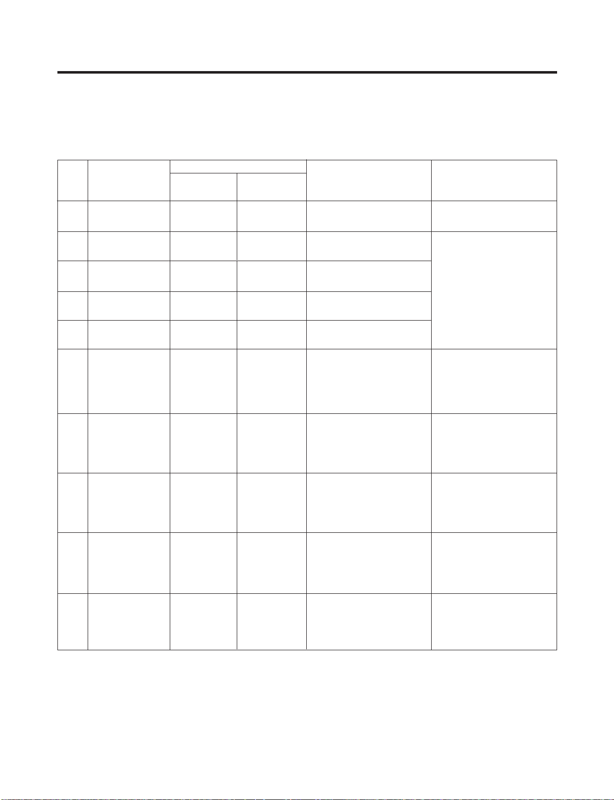
6-1. Error Code Summary
ww
WARNING : When you check the Resistance values, be sure to turn off the power.
And wait for the voltage-discharge sufficiently.
6. TROUBLESHOOTING
1
2
3
4
5
6
7
8
9
10
Normality
Freezer Sensor
Error
Refrigerator
Sensor Error
Defrosting
Sensor Error
Icing Sensor
Error
Poor Defrosting
Abnormality of
BLDC FAN Motor
for Ice Making
Abnormality of
BLDC FAN Motor
for Freezer
Abnormality of
BLDC FAN Motor
for Mechanic Room
Communication
Error
None
Short or Disconnection
of Freezer Sensor
Short or Disconnection
of Refrigerator Sensor
Short or Disconnection
of Defrosting Sensor
Short or Disconnection
of Icing Sensor
Even though it is passed
1 hour since then
Defrosting , if Defrosting
sensor is not over 8°C, it
is caused
It is caused when
feedback signal isn’ t
over 115
seconds during BLDC
FAN motor operating
It is caused when
feedback
signal isn ’ t over 115
seconds during BLDC
FAN motor operating
Communication Error
between Micom of Main
PCB and Display Micom
It is caused when
feedback
signal isn’ t over 115
seconds during BLDC
FAN motor operating
Normal operation of Display
Check each sensor and its
connector.
Temperature Fuse
Disconnection, Heater
disconnection, DRAIN Jam,
Poor Relay for Heater
Poor BLDC Motor
connection, DRIVE IC, and
TR Tx/Rx between icemaker
and main board.
Poor BLDC Motor
connection, DRIVE IC, and
TR Tx/Rx between icemaker
and main board.
Poor BLDC Motor
connection, DRIVE IC, and
TR Tx/Rx between icemaker
and main board.
Poor Communication
connection,Poor TR of
Transmitter and Receiver
Tx/Rx between icemaker
and main board.
Er
Er
Er
Er
Er
Er
Er
Er
Er
FS
rS
dS
IS
dH
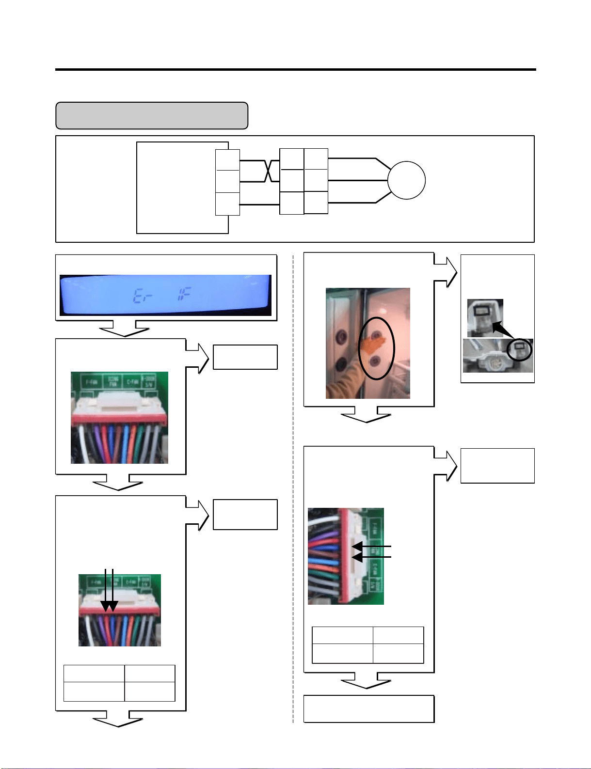
IF
FF
CF
CO
NO
Error Detection
Category
Error Generation Factors Remark
Freezer
Temperature
Ref.
Temperature
Error Display
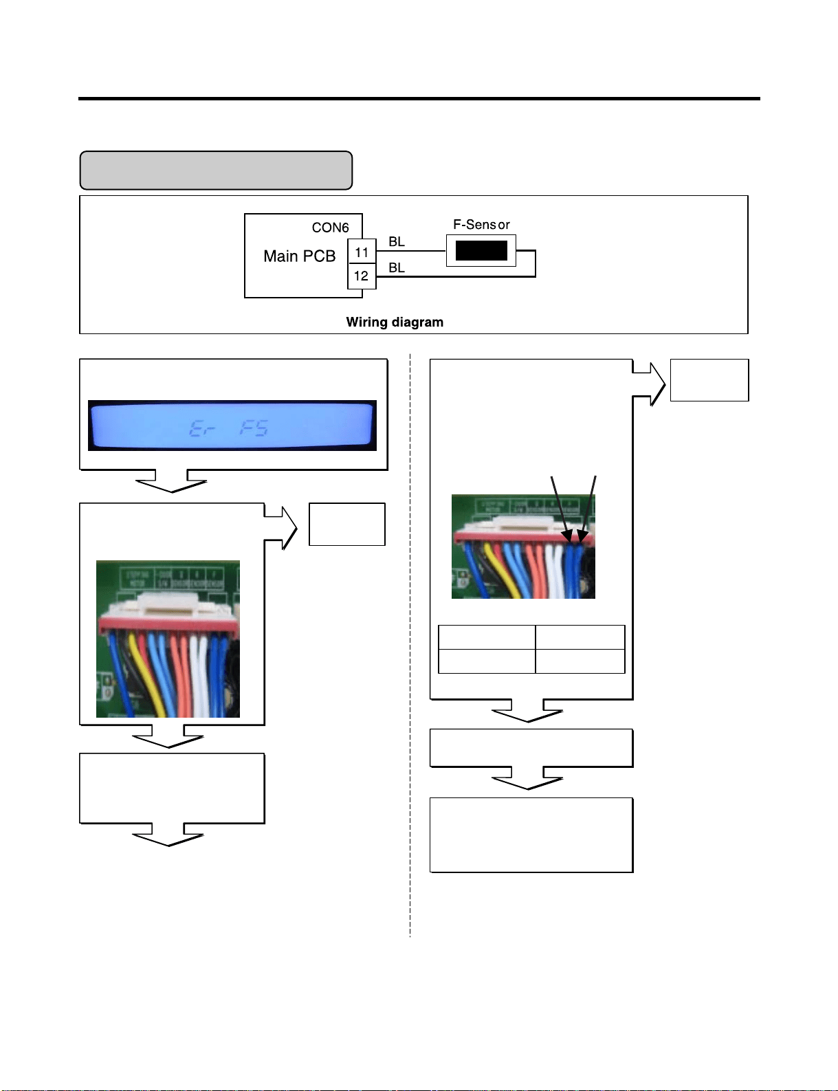
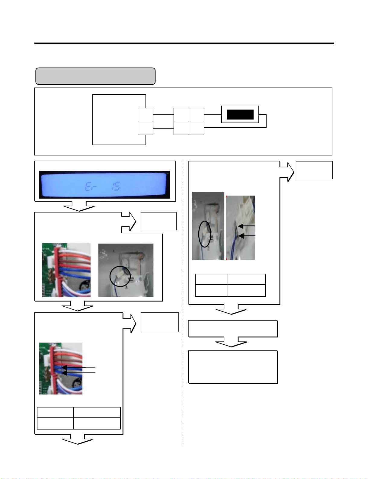
6-2. Troubleshooting With Error
- 18 -
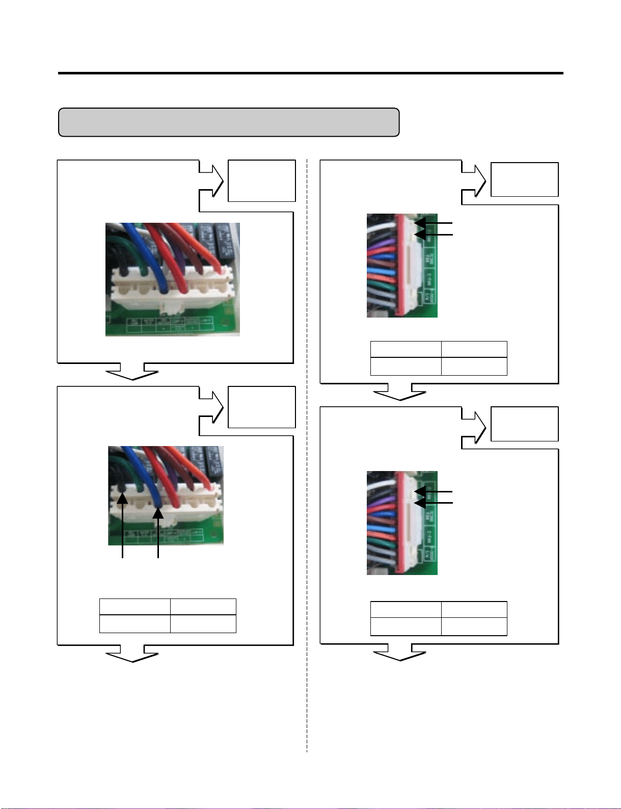
Is Er-FS dis played?
Disconnect CON6 and measure
the value. Is resistance value
between pins 11 & 12 of CON6
as below? (BL to BL)
Freezer Sensor Err or
Is the connection loose?
If the ER-FS appears, Replace
the main PCB. Otherwise,
explain to the customer!
Replace
F-sensor
pin12
pin11
1.4 ~ 120k‰pin11 to pin12
ResultTest Point
Reconnect
Reconnect CON6 and Power ON
Power Off
Tip : To protection of MICOM
Yes
Yes
No
No
No
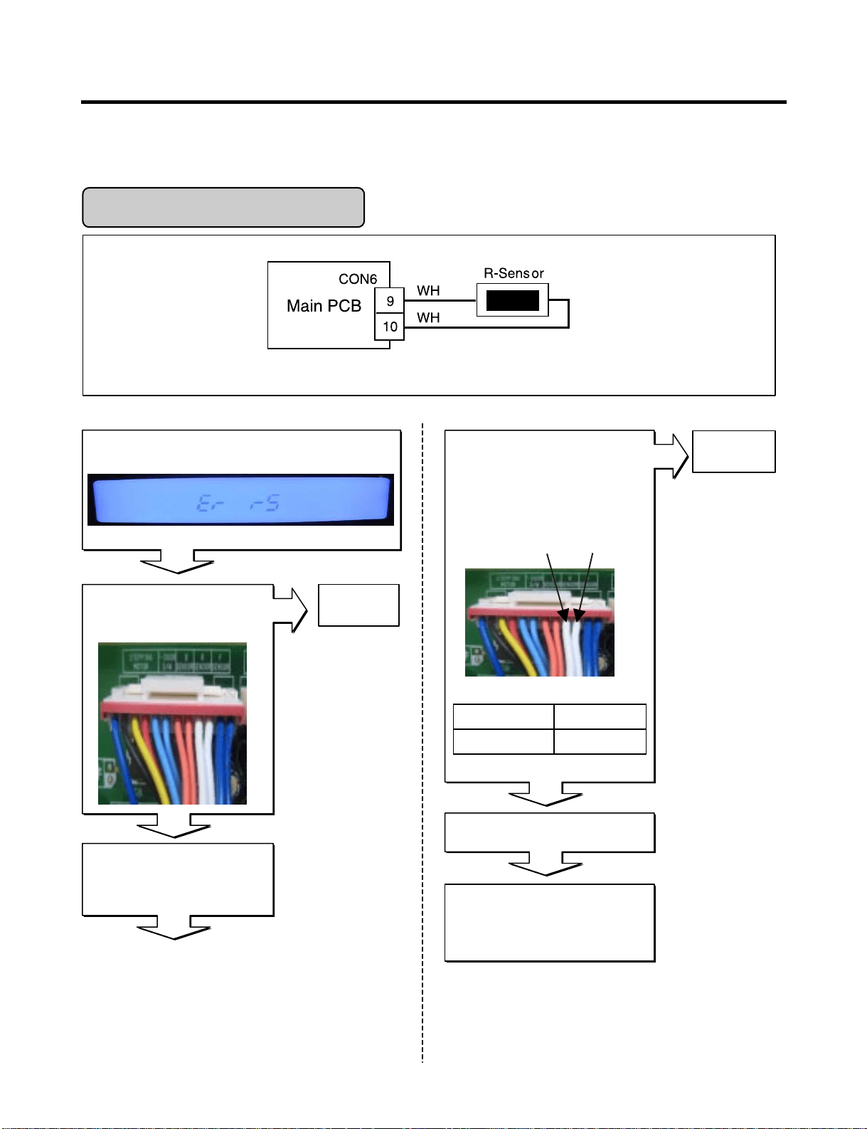
- 19 -
Refrigerator Sensor Error
Is Er-rS displayed?
Disconnect CON6 and measure
the value. Is resistance value
between pins 9 & 10 of CON6 as
below? (WH to WH)
Yes
Is the connection loose?
If the ER-rS appears, Replace
the main PCB. Otherwise,
explain to the customer!
Replace
R-sensor
No
pin10
pin9
Yes
6 ~ 300 k‰pin9 to pin10
ResultTpin10 pin9
Reconnect
Reconnect CON6 and Power ON
Power Off
Tip : To protection of MICOM
No
No
Wiring dia gram
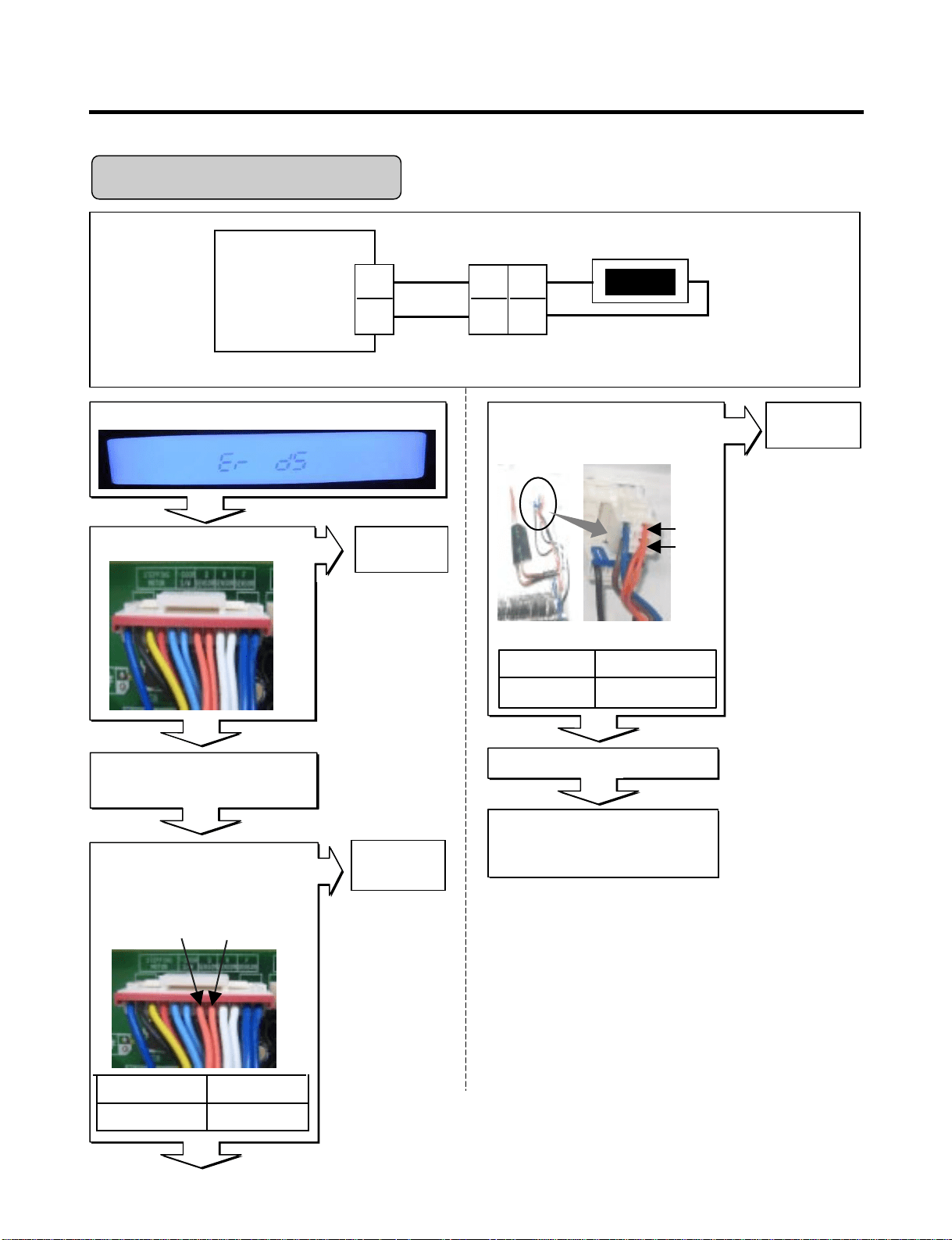
- 20 -
Housing-A
Main PCB
BO
BO
BO
BO
D-Sensor
7
8
2
1
CON6
7
6
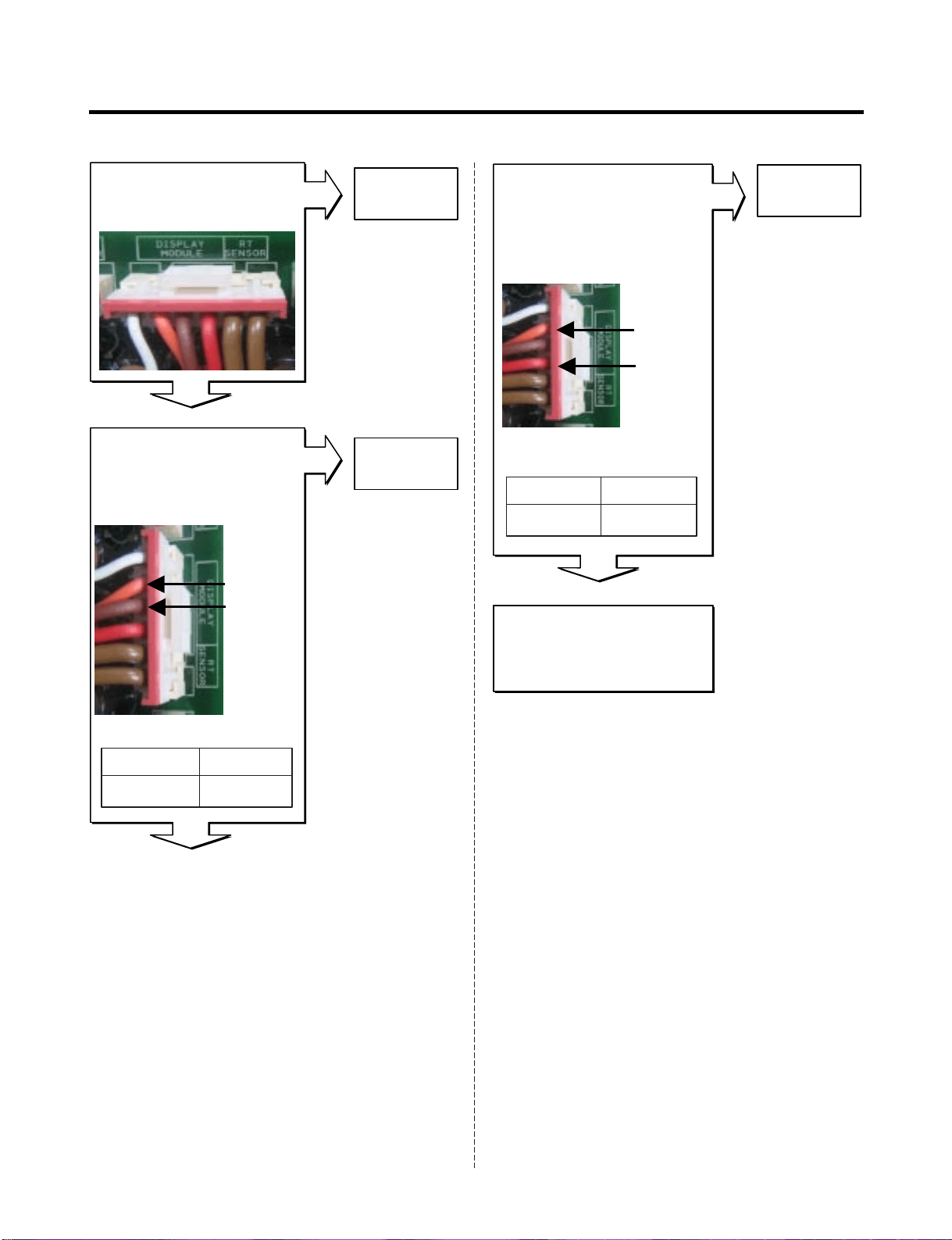
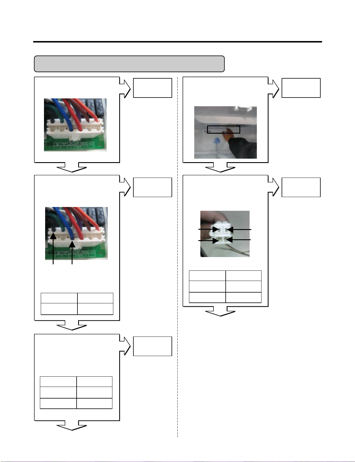
Defrost Sensor Error
Wiring dia gram
Is Er-dS displayed?
Disconnect CON6 and measure
the value. Is resistance value
between pins 7 & 8 of CON6 as
below? (BO to BO)
Yes
Is the connection loose?
If the ER-dS appears, Replace
the main PCB. Otherwise,
explain to the customer!
Replace
D-sensor
No
No
No
pin8
pin7
6 ~ 300k‰Pin7 to pin8
ResultTest Point
Reconnect
Reconnect and Power ON
Power Off
Tip : To protection of MICOM
Is resistance value between
pins 1 & 2 of Housing- A as
below? (BO to BO)
Replace a
D-Sensor
pin1
pin2
1.156 ~141.5k‰Pin1 To pin2
ResultTest Point
Checking Open or Short of wire
Yes
Yes
No
- 21 -
Is Er-IS displayed?
Yes
Yes
Yes
No
No
Yes
Housing-A
Display
PCB
BL
BL
BL
BL
Icing-Sensor
CON101
1
2
1
2
1
2
Is the connection loose?
Reconnect
pin1 BL
pin2 BL
Icing Room Sensor Error
1.156 ~141.5k‰pin1 to pin2
ResultTest Point
Icing room Sensor Resistance
Replace the
Icing-Sensor
(1) To (2)
Test Point Result
1.4 ~120k‰
Checking Open or Short of wire
pin2 BL
pin1 BL
Replace
Main PCB
If the ER-IS appears,
Replace Main PCB
Otherwise, explain
to the customer!
Reconnect and Power ON
Display PCB Inner of Icing door
Is resistance value between
pins 1 & 2 of Housing- A as
below? (BL to BL)
No
Disconnect CON101 and
measure the value. Is resistance
value between pins 1 & 2 of
CON101 as below? (BL to BL)
Wiring diagram
- 22 -
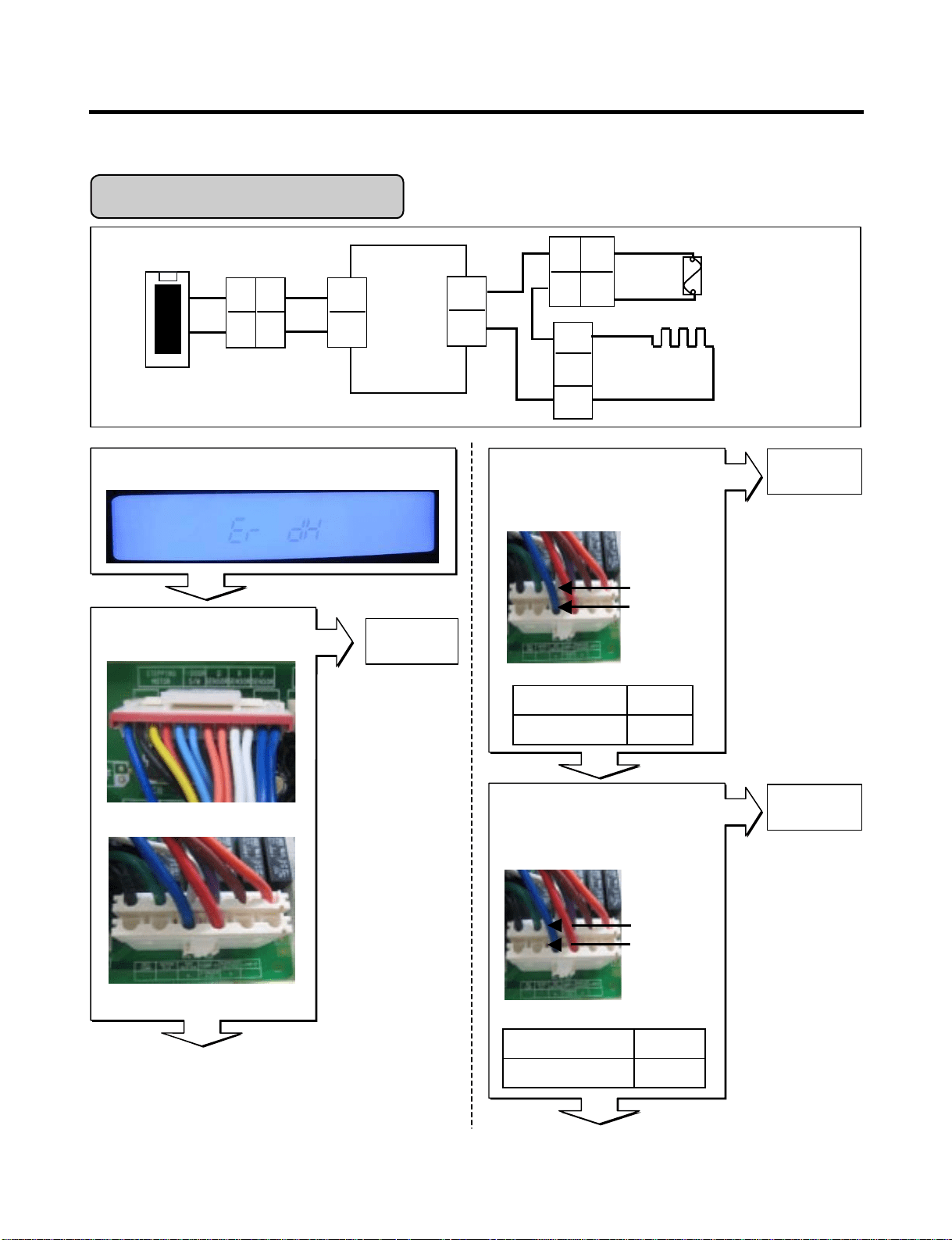
Enter the TEST 3 MODE
Is the voltage value
between pins 10 (WH) and
4 (BL) of CON3 115 V AC?
Is Er-dH displayed?
Yes
Yes
Yes
No
Yes
Yes
No
CON6
CON3
Replace
MAIN PCB
Replace
MAIN PWB
Main
PCB
WH
BL
FUSE-M
CON3
10
4
DEF-Heater
Housing-A
BO
D-Sensor
7
8
BO
2
CON6
BO
BO
7
6
BL
BN
BK
2
1
7
6
1
3
1
2
BK
Is the connec tion loose?
pin4 BL
pin10 WH
pin4 BL
pin10 WH
115Vpin4 To pin 10
ResultTest Point
Reset TEST3 MODE(Normal)
Is the voltage value between
pins 10 (WH) and 4 (BL) of
CON3 for 0 V AC?
0 ~ 2 V
Reset/Norm op
ResultTest Point
Defrost Heater Error
Wiring dia gram
Relay Open
Reconnect
Relay operation
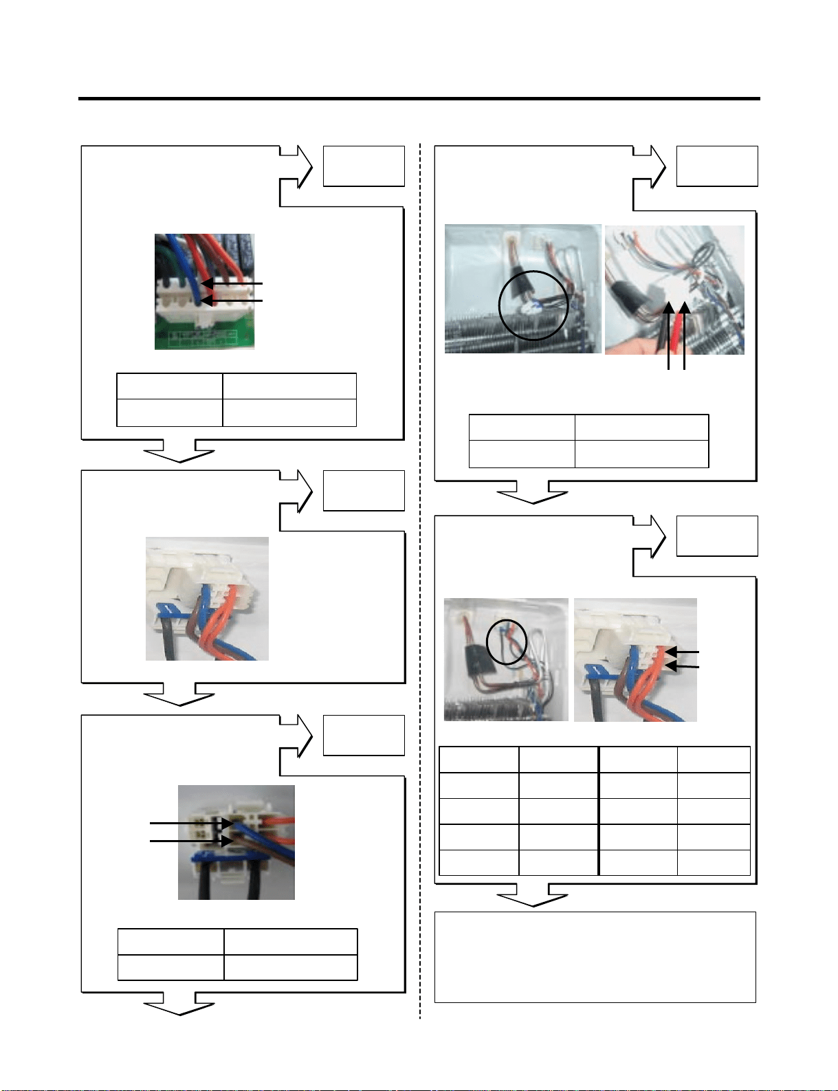
- 23 -
Explain to the customer! :
It can be occurred, when the gasket is not
stuck to product or when you put the high
temperature loads (hot foods) a lot
in the product.
Normal
Is the resistance value
between pins 10(WH)
And 4(BL) of CON3
like as below?
Replace
DEF-sensor
Yes
Yes
Yes
Yes
Yes
No
No
No
No
No
Is the resistance value of
heater like as below?
(2)
(1)
Replace
Heater
Test Point Result Test Point Result
-30°C 129.3 kΩ 10°C 19.53 kΩ
-20°C 76.96 kΩ 20°C 13.03 kΩ
-10°C 47.34 kΩ 30°C 8.896 kΩ
0°C 30 kΩ 40°C 6.201 kΩ
(2) BO
(1) BO
Heater Resistance
Defrost Sensor Resistance
Is the resistance
value of DEF-sensor like
as below? It depends on
the temperature.
Replace
Fuse-M
Is the resistance value
of Fuse –M like
as below?
(2) BN
(1) BL
Open or Short of Fuse-M
pin4 BL
pin10 WH
34 ~ 42 Ω (1) To (2)
RessultTest Point
34 ~ 42 Ω (1) To (2)
RessultTest Point
0 Ω (1) To (2)
RessultTest Point
Resistance
Is the connection loose?
Reconnect

- 24 -
Is Er-FF displayed?
Yes
Yes
Yes
Yes
Yes
Is the connection loose?
Reconnect
Housing
Main
PCB
WH
CON4
1
2
3
1
2
3
BK
PR
F-FAN
1
2
3
BK
RD
PR
Check fan motor
(Connector,
Frozen,Locked)
Is the feedback voltage
between pin2 and pin3 of
CON4 like as below?
(from motor to main board)
No
No
No
No
Wiring diagram
Feedback Voltages
Replace
Main PCB
Replace
Main PCB
Pin1 WH
Pin2 BK
Pin3 PR
Pin2 BK
Freezer Fan Voltages
Reset and
Enter the TEST 1 MODE
Is the output voltage between
pin1 and pin2 of
CON4 like as below?
Does the cold-air come out
of the top of the main duct?
Explain to the customer!
Freezer Fan Error
12 ~ 16 V
pin1 to pin2
RessultTest Point
RessultTest Point
1 ~ 4 Vpin2 to pin3
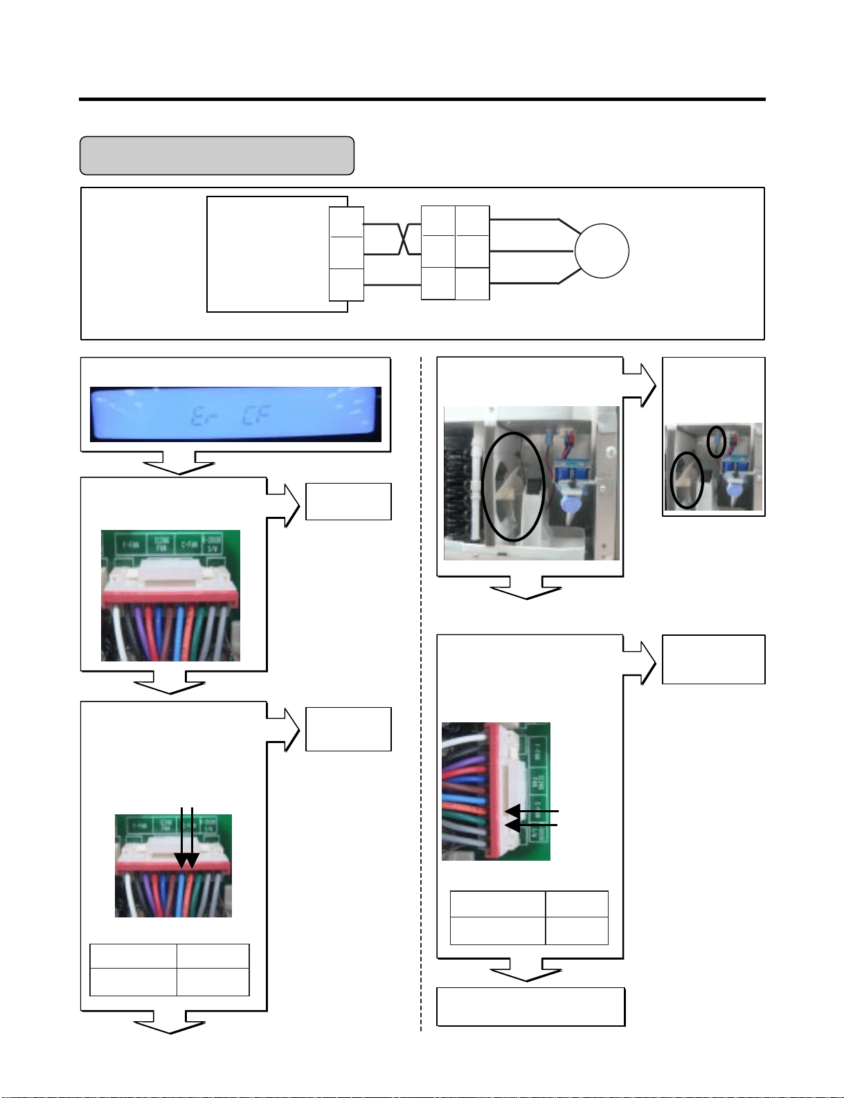
- 25 -
Housing
Main PWB
SB
CON4
7
8
9
1
2
3
BO
GN
C-FAN
1
2
3
BK
RD
PR
Wiring diagram
Is Er-CF displayed?
Yes
Yes
Yes
Yes
No
No
Yes
No
No
Is the connection loose?
Reconnect
Is the feedback voltage
between pin8and pin9 of
CON4 like as below?
(from motor to main board)
Pin9 GN
Pin8 BO
Replace
Main PCB
Replace
Main PCB
Pin7 SB Pin8 BO
Condenser Fan Voltages
Reset and
Enter the TEST 1 MODE
Is the output voltage between
pin7 and pin8 of
CON4 like as below?
Explain to the customer!
Check fan motor
(Connector,
Locked,mouse)
Is the condenser fan
rotate?
Condenser Fan Error
12 ~ 16 V
pin7 to pin8
RessultTest Point
Feedback Voltages
1 ~ 4 V
pin8 to pin9
RessultTest Point
- 26 -
Housing
Main PWB
CON4
4
5
6
4
5
6
Icing
FAN
4
5
6
BK
RD
PR
Wiring diagram
Is Er-IF displayed?
Yes
Yes
Yes
Yes
Yes
Is the connection loose?
Reconnect
Replace
Main PCB
Is the feedback voltage
between pin5 and pin6 of
CON4 like as below?
(from motor to main board)
N0
N0
N0
N0
Pin4 RD Pin4 BL
Pin5 BL
Pin6 BN
Icing Fan Voltages
Feedback Voltages
Replace
Main PCB
Reset and
Enter the TEST 1 MODE
Is the output voltage between
pin4 and pin5 of
CON4 like as below?
RD
BL
BN
Explain to the customer!
Check fan motor
(Connector,
Frozen,Locked)
Does the cold-air come out
of the side duct?
Icing Room Fan Error
12 ~ 16 V
pin4 to pin5
RessultTest Point
1 ~ 4 V
pin5 to pin6
RessultTest Point
- 27 -
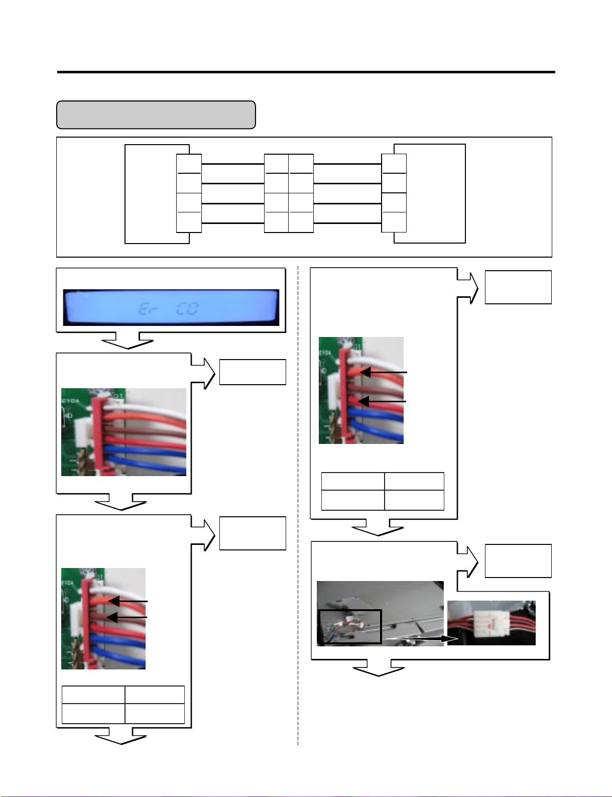
Is Er-CO displayed?
Yes
Yes
Yes
Yes
No
Yes
No
No
No
Display PCB
Is the connection loose?
MAIN
PCB
DISPLAY
PCB
1
2
3
4
Hinge
RD(Rx)
BN(Tx)
BO(GND)
WH/BK(12V)
RD(Tx)
BN(Rx)
BO(GND)
WH/BK(12V)
1
2
3
4
6
5
4
3
CON5 CON101
1
2
3
4
* Rx: Receiver
Tx: Transmitter
Replace the
Display PCB
Display PCB
Is the voltage between
pins 4 and pin 5 of
CON101?
pin5 BO
pin4 BN
Reconnect
Reconnect
Replace
Display PCB
Display PCB
Is the voltage between
pin3 and pin5 of CON101
0 V or 5 V?
Pin5 BO
Pin3 RD
Is the joint connection
loose In the Hinge?
Wiring diagram
Transmitter Voltages
Receiver fail Voltages
Communication Error
0 V or 5 V
pin4 to pin5
RessultTest Point
0 V or 5 V
pin3 to pin5
RessultTest Point
- 28 -
Replace the
Main PCB
After plug in,
If Er-CO is disappeared,
Explain to the customer!
Replace
Main PCB
Main PCB
Is the connection loose?
Main PCB
Is the voltage between
pin2 and pin4 of CON5
0 V or 5 V?
Main PCB
Is the voltage between
pins 2 and pin 3 of
CON5 0V or 5V?
No
Yes
Yes
Yes
Reconnect
pin2 BO
pin3 BN
pin2 BO
pin4 RD
Transmitter Voltages
Receiver Voltages
No
No
0 V or 5 V
pin2 to pin3
RessultTest Point
0 V or 5 V
(1) to (2)
RessultTest Point
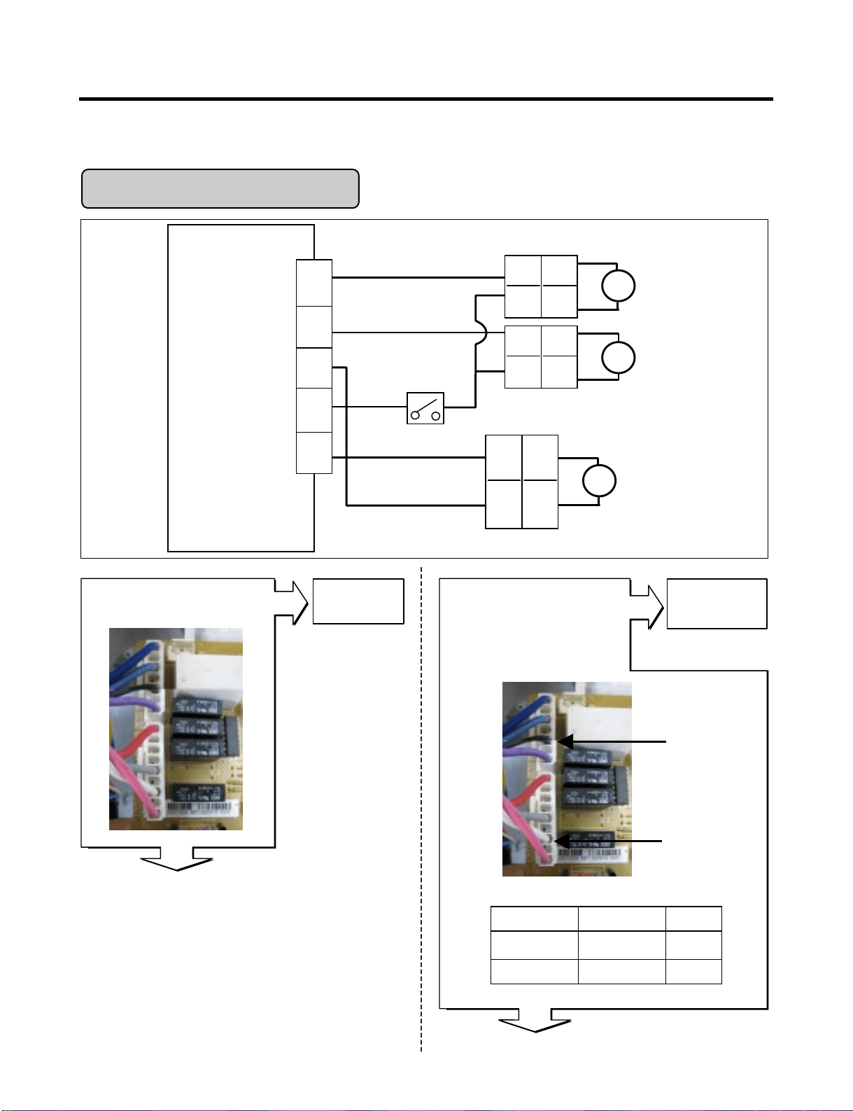
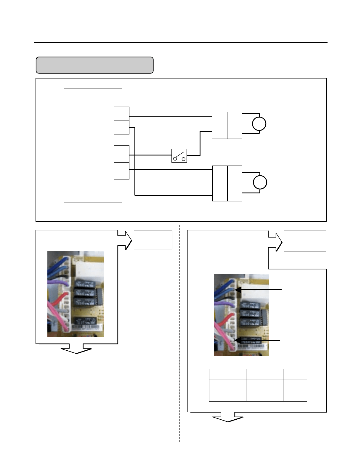
6-3. Troubleshooting Else
- 29 -
Housing-A
BK
CON2
WH
Housing-B
CUBE
Solenoid
S
SB
Auger
Motor
1
2
2
1
V
Lever S/W
Solenoid
Dispenser
S
2
1
RD
BL
RD
BL
BK
BK
BK
BK
CON3
1
2
Dispenser PCB
Is the connection loose?
Yes
Yes
No
No
Reconnect
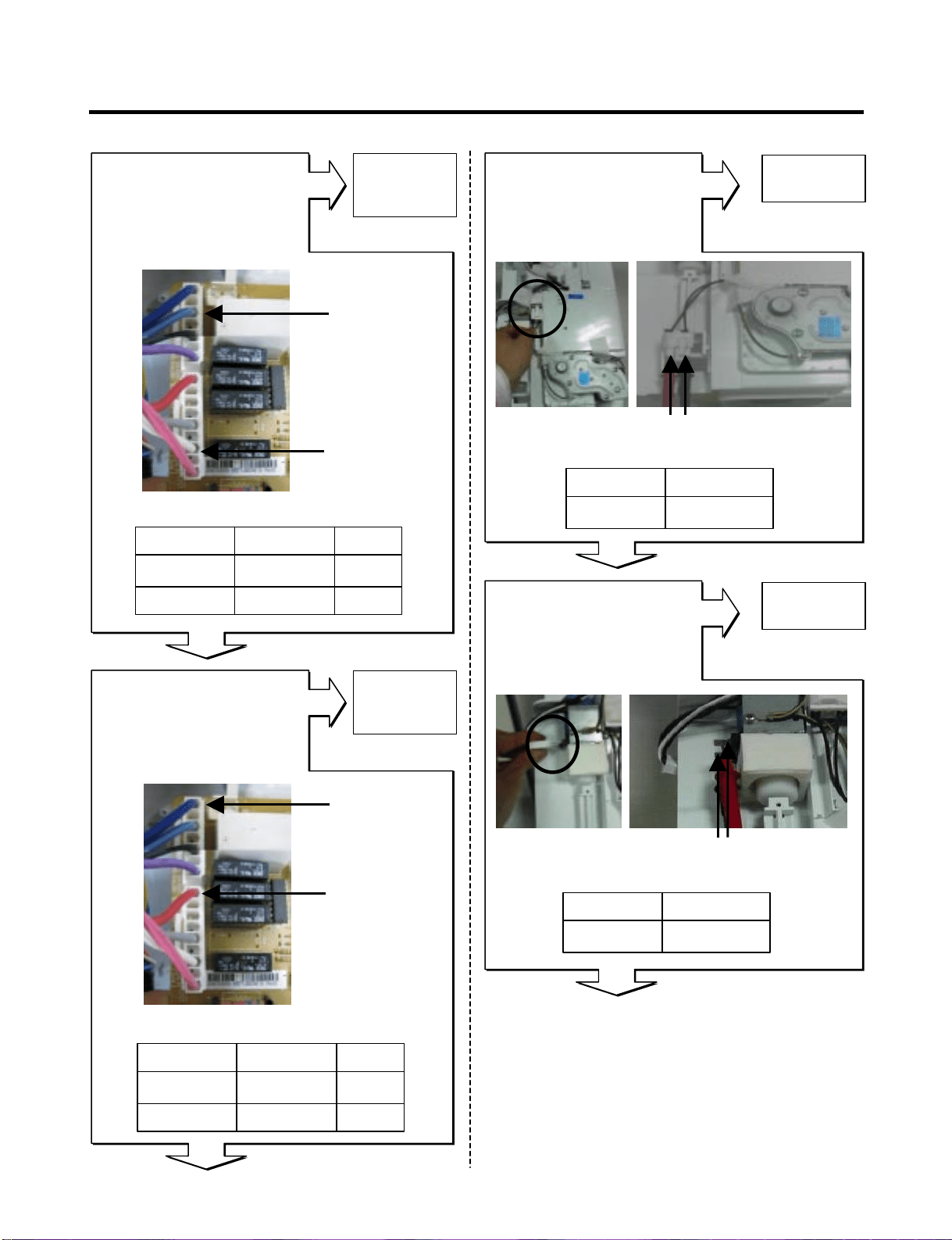
In CUBE Mode,
Is the voltage between pin3
of CON2 and pin3 of CON3
like as below, while
pushing the lever switch?
CON2
Pin3 BK
CON3
Pin3 WH
Test PointLevel switch Result
pin3 to pin3 Pushing 115 V
pin3 to pin3 Normal 0 ~ 2 V
Wiring diagram
7
4
2
1
Relay open of cube solenoid
Replace
Dispenser
PCB
Dispenser
PCB
3
5
3
9
7
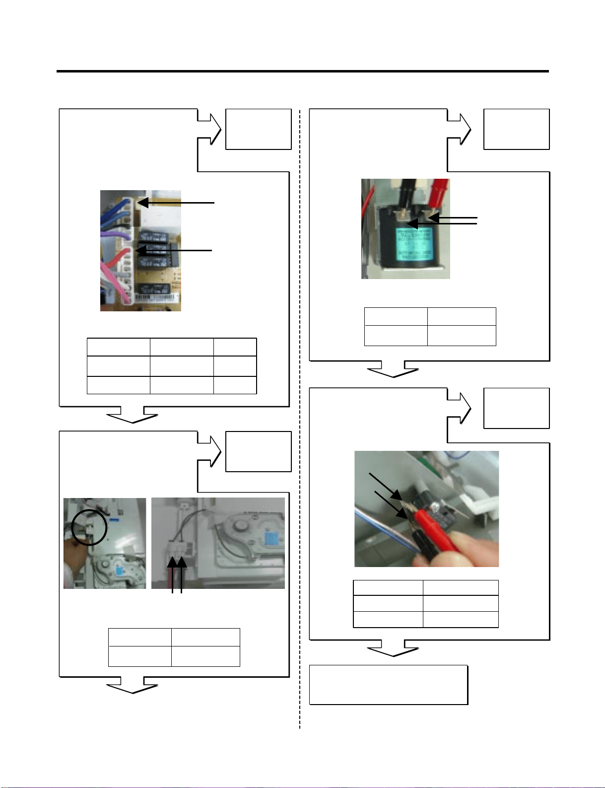
CUBE Mode doesn’t work
- 30 -
No
No
No
Yes
Yes
Yes
Yes
No
CON2
Pin5 SB
CON3
Pin3 WH
CON2
Pin7 BL
CON3
Pin9 RD
(1 )
(2 )
2.38 ~ 4.02 Ω(1) To (2)
ResultTest Point
Output voltage of dispenser solenoid
Output voltage of auger motor
Resistance of Auger Motor
32 ~ 40 Ω(1) To (2)
ResultTest Point
Resistance of Cube solenoid
(1)(2)
Is the resistance value
between (1) and (2) of the
Auger motor like as below?
Is the resistance value
between (1) and (2) of the
cube solenoid like as below?
Replace
Dispenser
PCB
Replace
Auger Motor
Replace
Cube Solenoid
Replace
Dispenser
PCB
Level switch Test Point Result
Pushing
Normal
pin5 to pin3
pin5 to pin3
115 V
0 ~ 2 V
Level switch Test Point Result
Pushing
Normal
pin7 to pin9
pin7 to pin9
115 V
0 V
In CUBE Mode,
Is the voltage between pin5
of CON2 and pin3 of CON3
like as below, while
pushing the lever switch?
In CUBE Mode,
Is the voltage between pin7
of CON2 and pin9 of CON3
like as below, while
pushing the lever switch?
- 31 -
No
Yes
Yes
No
(1)
(2)
Resistance of Dispenser solenoid
Replace
Dispenser
Solenoid
Replace
Micro
Switch
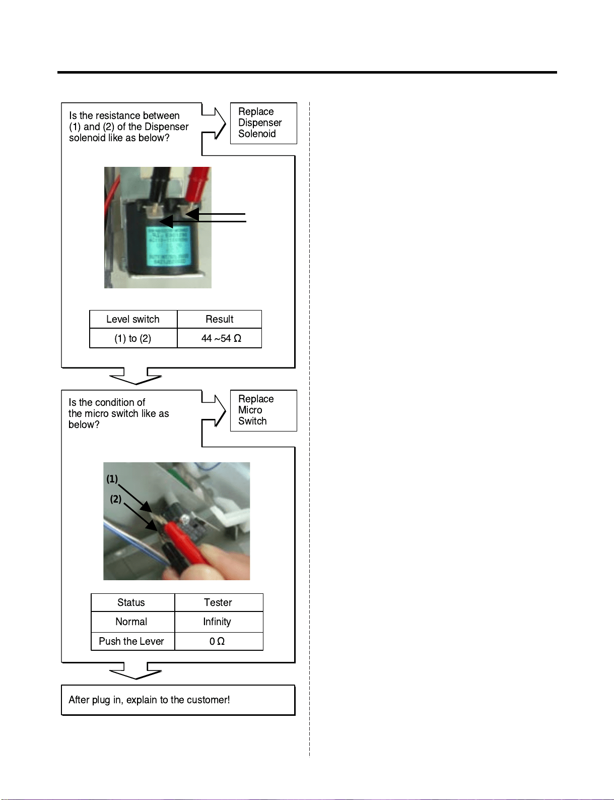
Level switch Result
(1) to (2) 44 ~54 ½
Status Tester
Normal
Push the Lever
Infinity
0½
Is the resistance between
(1) and (2) of the Dispenser
solenoid like as below?
Is the condition of
the micro switch like as
below?
(1)
(2)
After plug in, explain to the customer!
- 32 -
Display PCB
Is the connection loose?
Yes
Yes
No
No
Reconnect
In Crush Mode,
Is the voltage between pin5
of CON2 and pin3 of CON3
like as below, while
pushing the lever switch?
CON2
Pin5 SB
CON3
Pin3 WH
Test PointLevel switch Result
pin5 to pin3 Pushing 115 V
pin5 to pin3 Normal 0 V
Wiring diagram
Output voltage of Auger motor
Replace
Dispenser
PCB
Crush Mode Doesn't work
CON2
WH
Housing-B
SB
Auger
Motor
2
1
5
V
Lever S/W
3
CON3
Solenoid
Dispenser
S
2
1
RD
7
BL
1
4
2
1
9
Dispenser
PCB
- 33 -
CON2
Pin7 BL
CON2
Pin9 RD
(1) (2)
After plug in,
explain to the customer!
No
No
No
No
Yes
Yes
Yes
Yes
Replace
Dispenser
PCB
Replace
Dispenser
Solenoid
Replace
Micro
Switch
Replace
Auger Motor
In CUBE Mode,
Is the voltage between pin7
of CON2 and pin9 of CON3
like as below, while
pushing the lever switch?
Is the voltage between (1)
and (2) of the Dispenser
solenoid like as below?
Is the condition of
the micro switch like as
below?
Is the resistance value
between (1) and (2) of the
Auger motor like as below?
Output voltage of auger motor
Level switch Test Point Result
Pushing
Normal
pin7 to pin9
pin7 to pin9
115 V
0 V
2.38 ~ 4.02 Ω(1) To (2)
ResultTest Point
Resistance of Auger Motor
44 ~ 54 Ω(1) To (2)
ResultTest Point
Resistance of Dispenser solenoid
(1)
(1)
(2)
(2)
Status Tester
Normal Infinity
Push the Lever 0 Ω
- 34 -
Display PCB
Is the connection loose?
Yes
Yes
No
No
Reconnect
In Water Mode,
Is the voltage between
pin1 and pin7 of CON2 in
dispenser PCB like as
below, while pushing the
level switch?
Dispenser PCB
CON2
Pin7 BL
Dispenser PCB
CON2
Pin1 PR
Test PointLevel switch Result
pin1 to pin7 Pushing 115 V
pin1 to pin7 Normal 0 V
Wiring diagram
Output voltage of door water valve
Replace
Dispenser
PCB
Crush Mode Doesn't work
Dispenser
PCB
Main
PCB
7
BL
PR
Door
Water Valve
1
V
4
CON3
BL
GN
Machine Room
Water Valve
11
Housing-A
2
1
2
1
Housing-B
1
6
1
6
Lever S/W
CON2
V
- 35 -
No
Yes
No
Replace
Main PCB
Replace
Second
Water-valve
In Water Mode,
Is the voltage between
pin4 and pin11 of CON3 in
main PCB like as below,
while pushing the level
switch?
Second Water- valve
Is the resistance value of
Second-water valve like as
below?
No No
Replace
First
Water-valve
Replace
Micro
Switch
First Water- valve
Is the resistance value
between (1) and (2) of the
First-water valve like as
below?
Is the condition of
the micro switch like as
below?
After plug in,
explain to the customer!
Yes
Yes
Yes
Main PCB
CON3
Pin11 GN
Pin4 BL
(1)
(1)
(1)
(2)
(2)
(2)
115 Vpin4 to pin11
ResultTest Point
Output voltage of machine room water valve
360 ~ 420 Ω(1) to (2)
ResultTest Point
Checking resistance of Second-valve
Dispenser
Ice Maker
In door
360 ~420 Ω(1) to (2)
ResultTest Point
Status
Normal
Push the Lever
Tester
Infinity
0 Ω
Checking resistance of First-valve
Machine room
- 36 -
No
Yes
Yes
No
Replace
Door switch
Replace
Main PCB
Is the condition of
the freezer door switch
like as below?
Reconnect
Is the connection loose?
Is the voltage between pin 11
and 12 of CON6 like as
below?
No
Replace
Main PCB
Is the voltage between pin 4
and pin7 of CON3 like as
below?
Main PCB
SB
SB
F-DOOR Switch
CON6
5
6
Housing
Wiring diagram
SB
SB
7
4
F-Lamp
1
2
BO
BL
CON3
Pin5 SB
Pin6 SB
CON3CON6
DC Part
AC Part
Freezer-lamp Doesn’t work
Replace Lamp
No
Yes
Yes
Voltage of Door switch
Door
Closed
Open
Test Point
pin5 to pin6
pin5 to pin6
Result
5 V
0 V
Status
Normal
Push the Switch
Tester
0 Ω
Infinity
Voltage of Freezer lamp
Door
Closed
Open
Test Point
pin4 to pin7
pin4 to pin7
Result
0 ~ 2 V
115 V
Pin4 BL
Pin7 BO
CON3
- 37 -
No
Yes
Yes
No
Replace
Door switch
Replace
Main PCB
Is the condition of
the refrigerator door
switch like as below?
Reconnect
Is the connection loose?
Is the voltage between pin10
and pin11 of CON4 like as
below?
No
Replace
Main PCB
Is the voltage between pin4
and pin9 of CON3 like as
below?
Pin11 GY Pin10 GY
CON3CON6
AC
Part
DC
Part
Refrigerator-lamp Doesn’t work
Replace Lamp
No
Yes
Yes
Voltage of Door switch
Door
Closed
Open
Test Point
pin10 to pin11
pin10 to pin11
Result
5 V
0 V
Status
Normal
Push the Switch
Tester
0 Ω
Infinity
Voltage of Refrigerator lamp
Door
Closed
Open
Test Point
pin4 to pin9
pin4 to pin9
Result
0 ~ 2 V
115 V
Pin4 BL
Pin9 PR
CON3
CON4
MAIN
PCB
GY
GY
R-DOOR Switch
CON4
10
11
11
12
Hinge
4
12
GY
GY
GY
GY
Housing
1
9
4
R-Lamp
CON3
PR
BL
Wiring diagram
- 38 -
Yes
No
Yes
No
Replace
Replace the
Main PCB
MAIN PWB
Is the connection loose?
Reconnect
Main PCB
Enter the TEST 1 MODE
Is the voltage between
Pins 4 and pin 12 of CON3
like as below?
Is the voltage between
pins 1 and pin 2 of CON4
like as below?
No
Replace the
Main PCB
Feedback check.
Is the voltage between
Pin 2 and pin3 of CON4
like as below?
Pin1 WH
Pin2 BK
Pin12 BK Pin4 BL
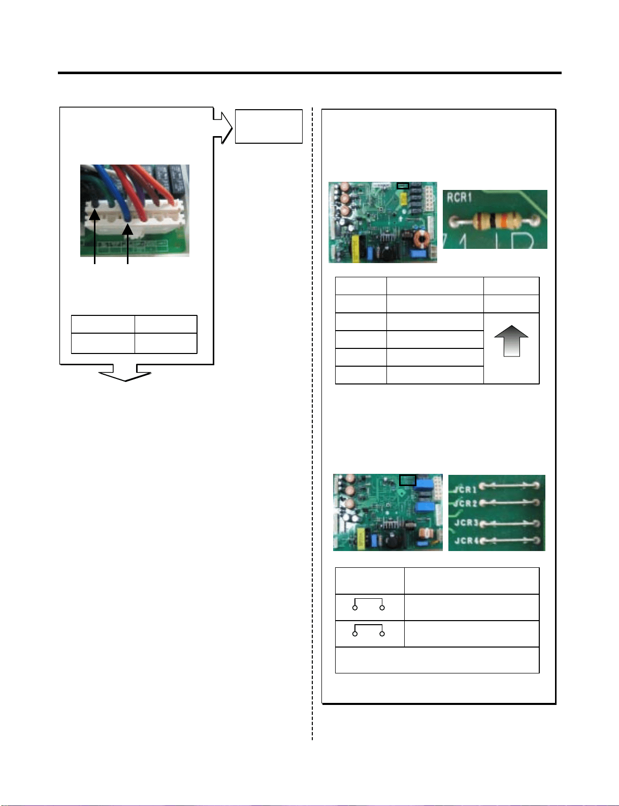
Poor cooling in the refrigerator compartment
Yes
Yes
Yes
Voltage of Compressor
Test Point
pin4 to pin12
Result
115 V
Voltage of F-fan
Test Point
pin1 to pin2
Result
12 ~ 16 V
Feedback voltage of F-fan
Test Point
pin2 to pin3
Result
11 ~ 4 V
CON4
CON3
CON3
Pin2 BK
Pin3 PR
CON4

- 39 -
Does the cold-air come out
of the top of the main duct?
After reset the unit, take steps to PCB as follows
for temperature compensation.
1. In the case of 6871JB1431 ( by July 2007)
: Compensate with replacing RCR1
2. In the case of EBR34917102
(from Aug 2007)
: Compensate with Jump wire cutting
* Change RCR1
* Cutting of jumper wire
Enter the TEST 2 MODE
Does not cold-air come
out of the top of the
main duct?
No
Yes
Yes
Check the
Damper itself
Check the
Damper itself
No
Replace
Damper
Checking Damper itself
Is the resistance
Values between (1) & (4),
(2) & (3) like as below?
No
(1)RD
(2)WH
(1)BL
(2)YL
Resistance of Damper
373 ~456 ‰
(1) to (4)
373 ~456 ‰
(2) to (3)
Ressult
Temp. CompensionRCR1
Temp. Compensation
Cutting both jumpers affords a 2…
temperature compensation
- 1.0 deg
- 1.0 deg
JUMP WIRE
Ressult
- 0.5 deg8.2 k‰
- 1 deg5.6 k‰
- 1.5 deg3.3 k‰
- 2 deg2 k‰
- 2.5 deg470 k‰
Current
Colder
Test Point
JCR3
JCR4
Yes
- 40 -
MAIN PWB
Is the connection loose?
Check the Fan operation by
placing your hand in front
of the vents to feel for any
cold air flow.
No
Yes
Yes
Reconnect
Replace Fan
No
Replace
Damper
Enter the TEST 1 MODE
Is the voltage between
Pins 4 and pin 12 of
CON3 like as below?
Voltage of Compressor
115 V
pin4 to pin12
RessultTest Point
Yes
Enter the TEST 2 MODE
Does the cold-air coming out
of the top of the main duct.?
Checking Damper itself
Is the resistance
Values between (1) & (4),
(2) & (3) like as below?
No
Yes
Yes
Check the
Damper itself
Replace
Damper
(1)RD
(2)WH
(3)BL
(4)YL
Resistance of Damper
373 ~456 Ω
(1) to (4)
373 ~456 Ω
(2) to (3)
RessultTest Point
OFF
Open
ON
Closed
Fan-MotorDoor
Yes
Over cooling in the refrigerator compartment
Yes
Pin12
BK
Pin4
BL
CON3
CON3
- 41 -
After reset the unit, take steps to PCB as follows
for temperature compensation.
1. In the case of 6871JB1431 ( by July 2007)
: Compensate with replacing RCR1
2. In the case of EBR34917102
(from Aug 2007)
: Compensate with Jump wire cutting
* Change RCR1
* Cutting of jumper wire
Temp. CompensionRCR1
Temp. Compensation
Cutting both jumpers affords a 2…
temperature compensation
+ 1.0 deg
+ 1.0 deg
JUMP WIRE
Ressult
+ 2.5 deg180 k‰
+ 2 deg56 k‰
+ 1.5 deg33 k‰
+ 1 deg18 k‰
+ 0.5 deg12 k‰
Current
Colder
JCR1
JCR2
Replace
Damper
Enter the TEST 3 MODE
Is the voltage between
Pins 4 and pin 12 of
CON3 like as below?
Voltage of Compressor
115 V
pin4 to pin12
RessultTest Point
Yes
Yes
Pin12
BK
Pin4
BL
CON3
- 42 -
TEST
BUTTON
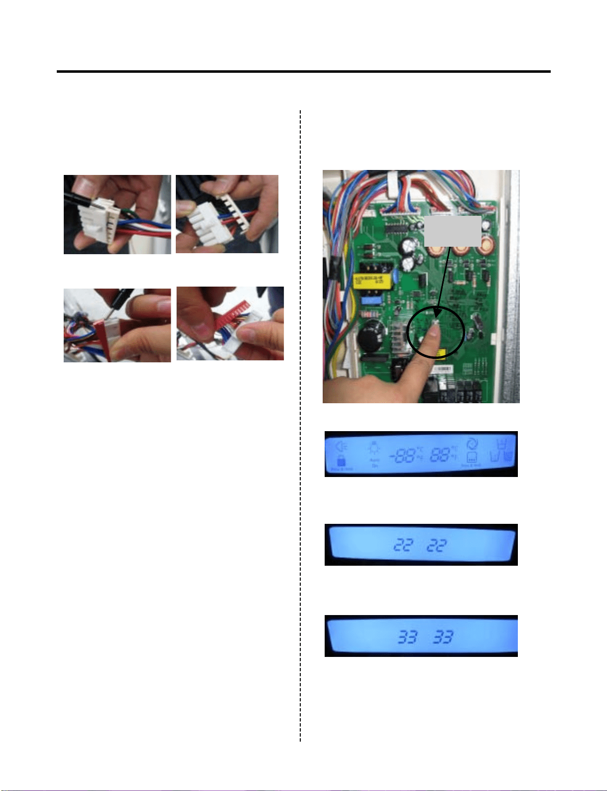
1. How To Remove Terminal Position
Assurance (TPA)
(NOTE)
3. How To Start Test Mode
Push the TEST button on the Main PWB,
You can start the TEST MODE.
2. Wire Color
BL : Blue
WH : White
BO : Bright Orange
BK : Black
BN : Brown
PR : Purple
RD : Red
GN
: Green
SB : Sky Blue
GY : Gray
* AC TPA
* 1 time : Comp / Damper / All FAN on,
(All things displayed)
* 2 times : Damper closed
(22 22 displayed)
* 3 times : Forced forced defrost mode
(33 33 displayed)
* DC TPA
After measure the values,
you should put in the TPA again.
- 43 -
4. How to check the Fan-Error
(1) 6871JB1431A ( ~ July 2007)
After sending a signal to the fan, the MICOM checks the BLDC fan
motor’s lock status. If there is no feedback signal from the BLDC fan,
the fan motor stops for 10 seconds and then is powered again for 15
seconds. To determine that there is a fan motor malfunction,
this process is repeated 5 times. If the fan motor is determined to be
defective, the error code will be shown continuously in the display.
At this point, there is no further check of the fan motor.
(2) EBR34917102 ( Aug 2007 ~)
After sending a signal to the fan, the MICOM checks the BLDC fan
motor’s lock status. If there is no feedback signal from the BLDC fan,
the fan motor stops for 10 seconds and then is powered again for 15
seconds. To determine that there is a fan motor malfunction,
this process is repeated 3 times. If the fan motor is determined to be
defective, the error code will be shown in the display for 30 minutes.
At this point, the process will be repeated until the fan motor operates
normally. If normal operation is achieved, the error display is erased and
the MICOM is reset automatically.
No signal
15s
10s
15s
10s
15s
10s
15s
10s
15s
Normal
drive
Error Display
No signal
15s
10s
15s
10s
15s
Normal drive
No signal Repeat
15s
10s
15s
10s Pause 30min
Pause 30min
10s
15s 15s
7-1. Defrost Controller Assembly
7. COMPONENT TESTING INFORMATION
- 44 -
(1) to (2)
(1) to (2)
- Controller assembly is consist of 2 kinds of part those are fuse-m
and sensor. we can decide part is defect or not when we
check the resistance.
- Fuse-m can cut off the source when defrost heater operate the
unusual high temperature.
- Sensor give temperature information to Micom
Function
How to
Measure
(Fuse-M)
Set a ohmmeter to the 2 housing pin.
Measure the 2 pin connected to
Fuse-M. If the ohmmeter indicate
below 0.1ohm fuse-m is a good
condition, But infinitely great ohm
Fuse-M is disconnection
How to
Measure
(Sensor)
Standard
Set a ohmmeter to The
2housing pin.
Measure the 2 pin
connected to Sensor.
If the ohmmeter indicate 11kΩ
(at room temperature)
Sensor is not a defect.
When check the ohm at other
temperature Check
the sensor manual.
Fuse-M (at all temperature) Sensor (at room temperature)
0 ~0.1 Ω
(1) to (2)
RessultTest Point
11 Ω
(1) to (2)
RessultTest Point
- 45 -
7-2. Sheath Heater
(2) (1)
Sheath heater is a part for defrost. All heating wire is connected to only
one line. So we can decide part is defect or not when we check the
resistance.
Set a ohmmeter connect to The 2 housing pin.
Measure the 2 pin connected to Sheath Heater.
If the ohmmeter indicate (V°øV)/Watt=R is good condition,
ex) when watt=350w, voltage=115v R=(115°ø115)/350=38Ω
But the ohmmeter indicate infinitely great
Sheath heater is disconnection
Function
How to
Measure
Standard Sheath heater (at all temperature)
34 ~42 Ω
(1) to (2)
RessultTest Point
- 46 -
7-3. Door Heater Assembly
The heater is designed to prevent the raising dew from door.Function
How to
Measure
Standard
2.3 ~2.9 Ω
(1) to (2)
RessultTest Point
- 47 -
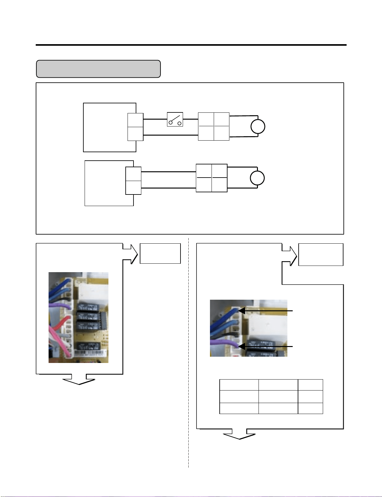
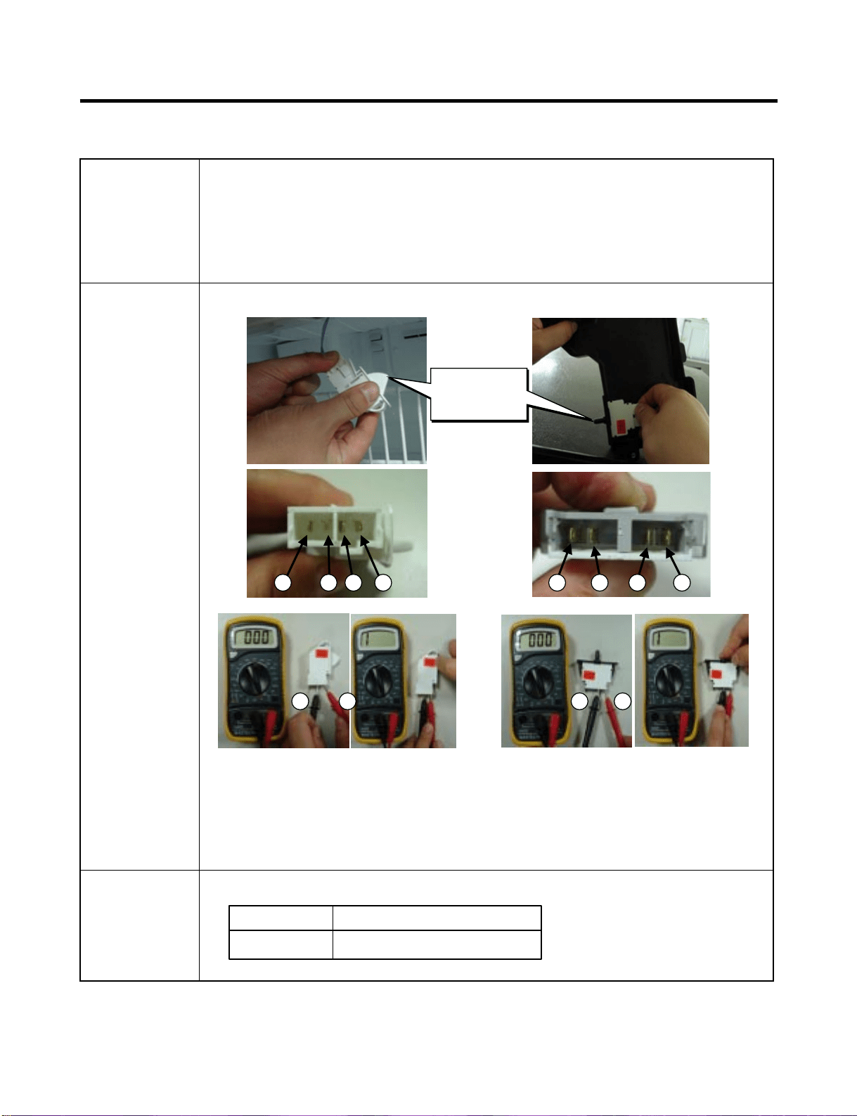
7-4. Door Switch
The switch sense if the door open or close.
- When the door open, lamp on.
- When the door open, the switch give information to Micom.
When the door open, internal contact operate on and off moving
plunger of door switch up and down.
Check the resistance between connectors 1,2 and 3,4 .It means
check whether or not applying an electric current. If there is
resistance, it means the switch not inferiority
Function
How to
Measure
<Switch, Freezer> <Switch, Refrigerator>
Beep Beep
Standard Multimeter beep – Switch F,R
None (∞ Ω)
Beep or 0 Ω
Push the button(Plunger)Nomal
1 2 4 1 2 3 43
3 4 2 1
Button
(Plunger)
- 48 -
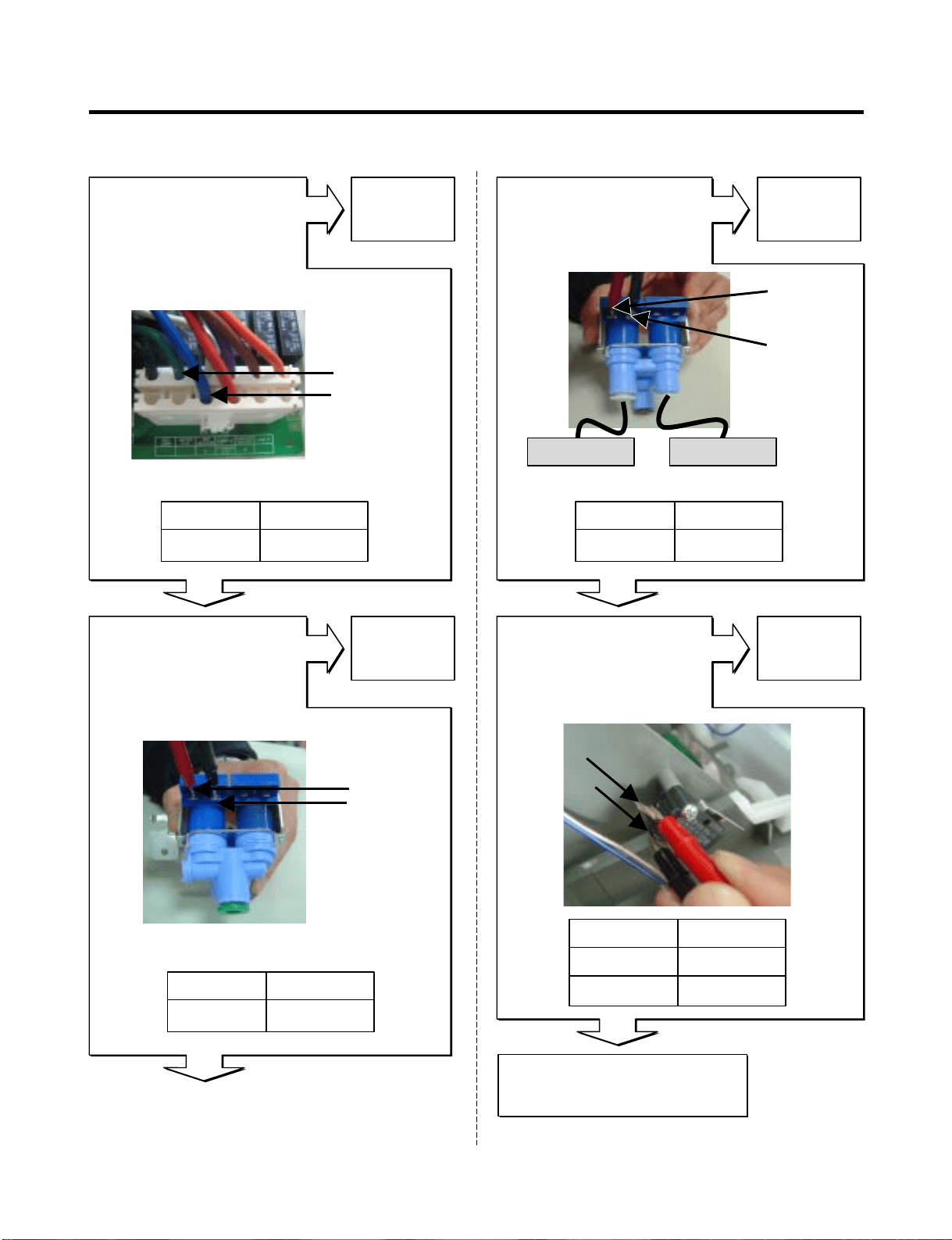
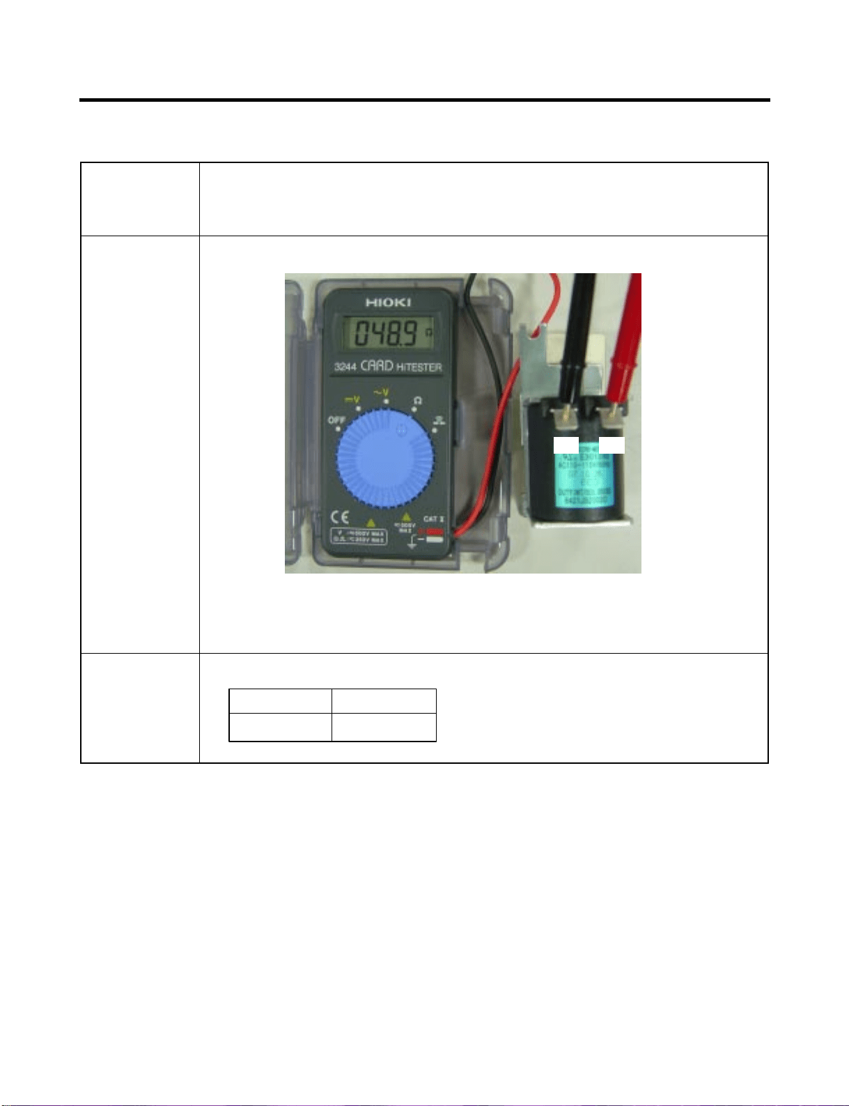
7-5. Solenoid
- Dispenser solenoid : When customer push the dispenser
button, Pull duct door and abstract from ice bank.
Function
How to
Measure
Dispenser Solenoid
Standard Dispenser Solenoid
44 ~ 54 Ω
(1) to (2)
ResultTest Points
(1) (2)
- 49 -
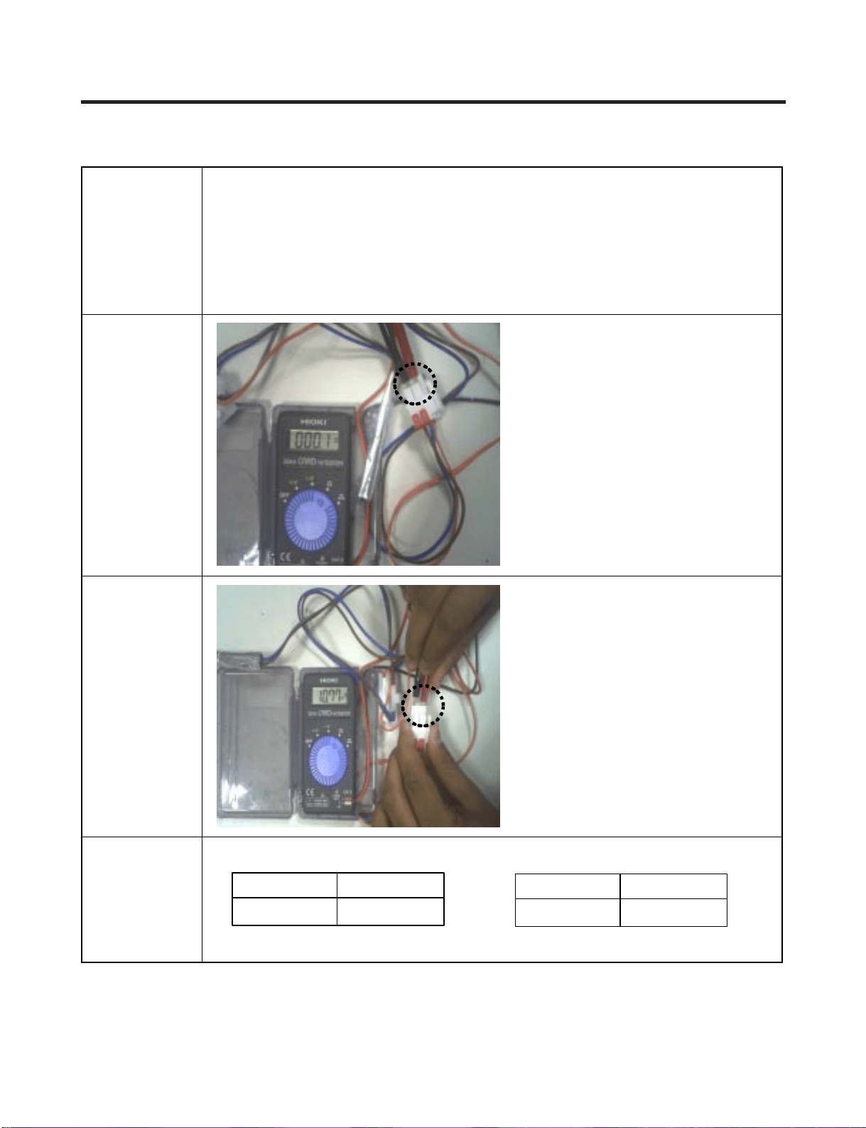
7-6. AC Motor ASSEMBLY (Geared Motor & Solenoid)
The Geared Motor of ac motor assembly advances forward the ice by
rotating the ice and The solenoid of ac motor assembly selects one of
the cube mode or crush mode.
- Cube solenoid : Pulling the stir lip for moving the ice in ice
maker system.
Check the resistance between connectors (Geared motor 1,2) and
(solenoid 3,4).It means check whether or not applying an
Electric current. If there is resistance, it means the geared motor or
solenoid is not inferiority
Function
How to
Measure
< Geared Motor > < Cube Solenoid >
Standard Geared Motor
2.38 ~ 4.02 Ω
(1) to (2)
ResultTest Points
Cube Solenoid
32 ~ 40 Ω
(3) to (4)
ResultTest Points
1
Take out the
male housing
from female
housing
2
Measure the
resistance
between
(1) and (2)
1
Remove the
female housing
from terminal.
2
Measure the res
istance between
(3) and (4)
Terminal
of solenoid
(1) (2)
(3)
(4)
T.P
- 50 -
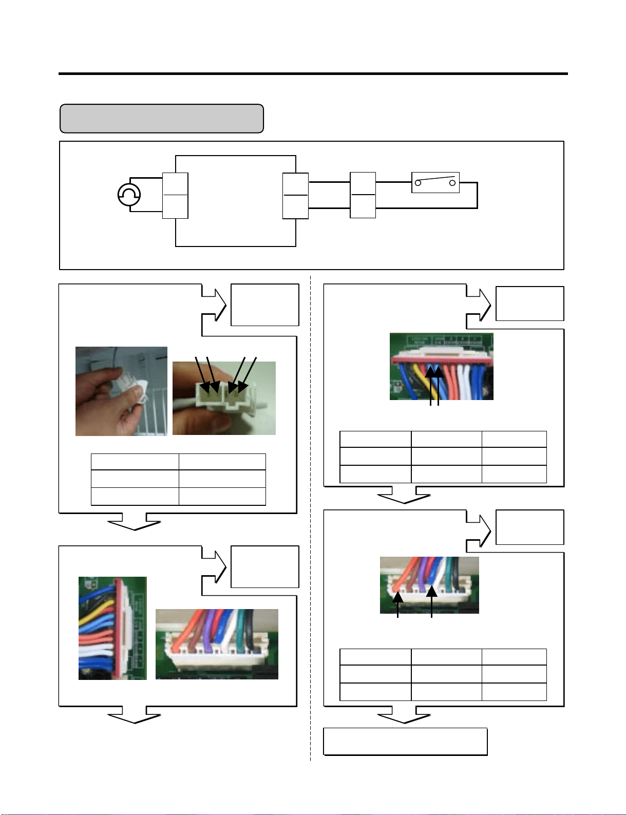
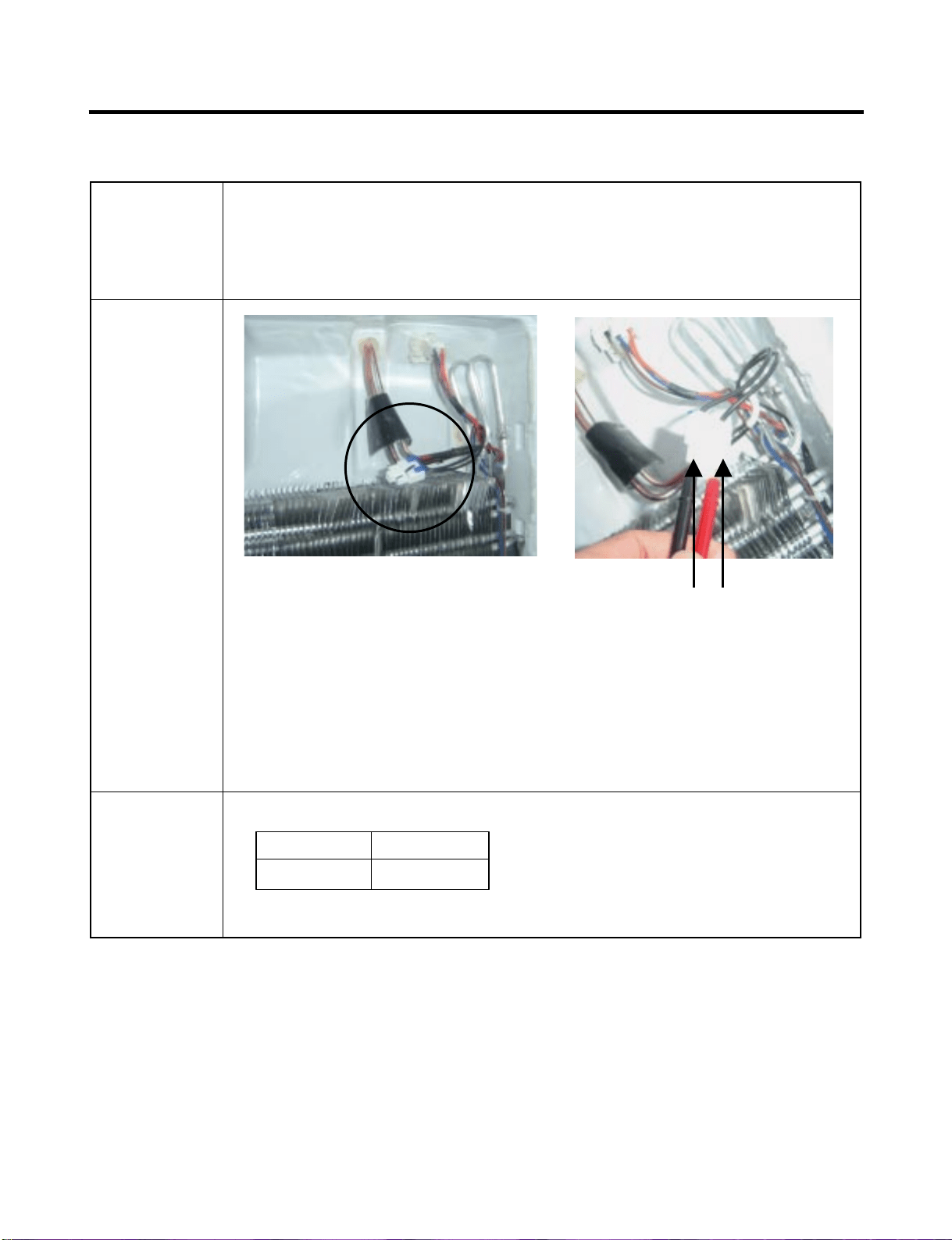
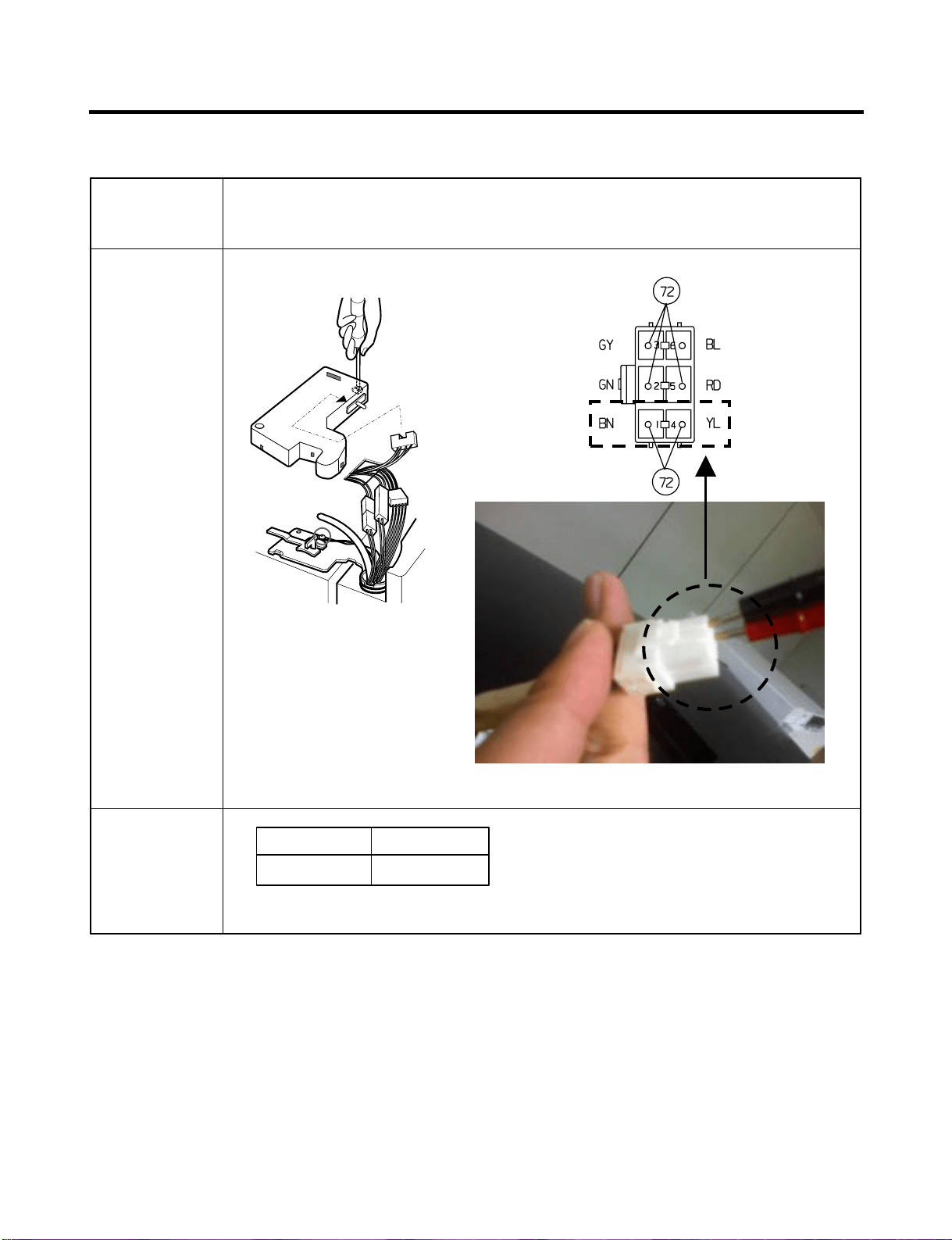
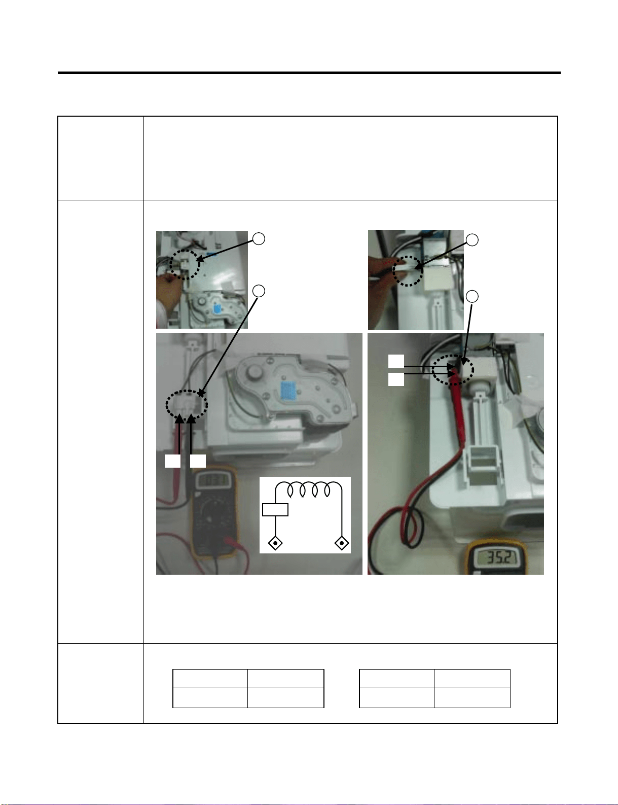
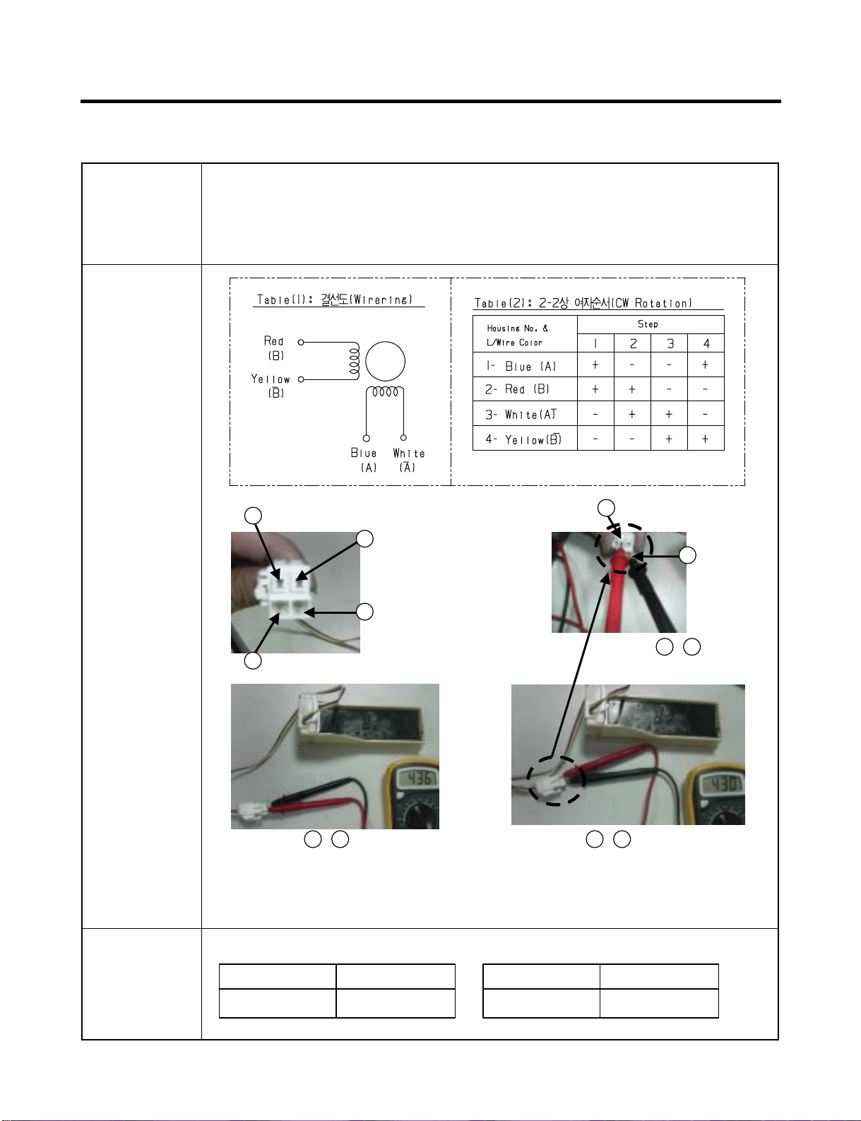
7-7. Damper
The damper supplies the cold air at freezer room to chillroom
by using the damper’s plate. Chillroom is colder than before
when damper’s plate is open. When damper’s plate is close,
chillroom’s temperature will rise.
Check the resistance between connectors 1,3 and 2,4 .It means
check whether or not applying an electric current. If there is
resistance, it means the damper not inferiority
Function
How to
Measure
extension
< Damper Circuit >
Standard Damper
373 ~ 456 Ω
Red and Yellow
ResultTest Points
373 ~ 456 Ω
Blue and White
ResultTest Points
1
Blue
1
Blue
2
Red
3
White
3
White
Checj the 1 , 3
Check the 1 , 3Check the 2 , 4
4
Tellow
- 51 -
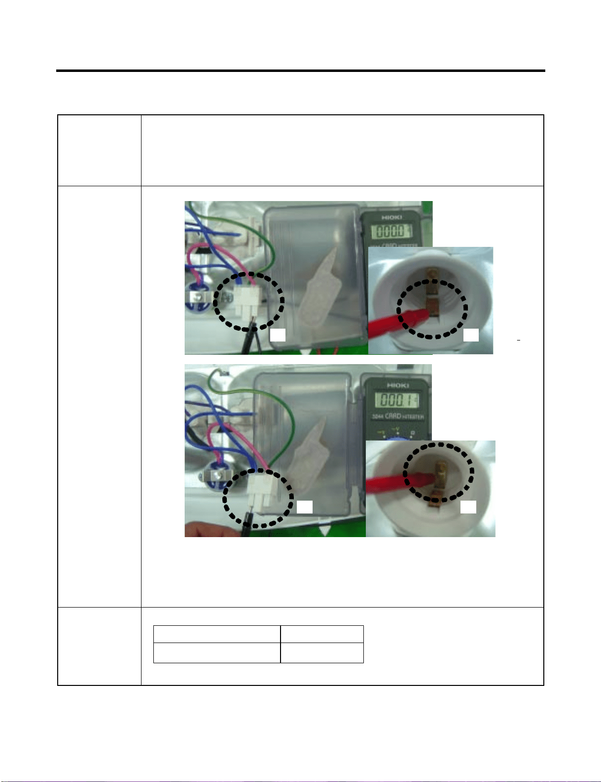
7-8. Lamp Socket
The lamp socket connect cover lamp assembly to lamp.
The lamp socket fix lamp and unite lamp and cover lamp assembly.
The lamp socket supply electric source to lamp also.
Check the resistance between connector of housing and connector of
lamp socket. It means check whether or not applying an electric current.
If there is resistance it means the lamp socket is not inferiority.
Function
How to
Measure
Standard
0 Ω
(1) to (2) and (3) to (4)
ResultTest Points
(1) (2)
(3) (4)
- 52 -
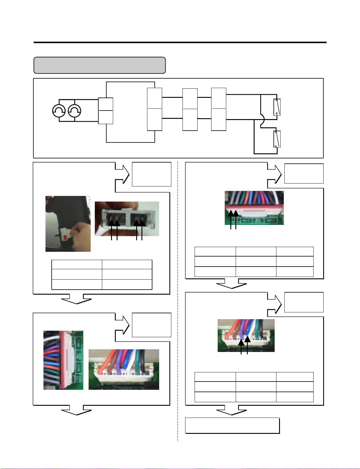
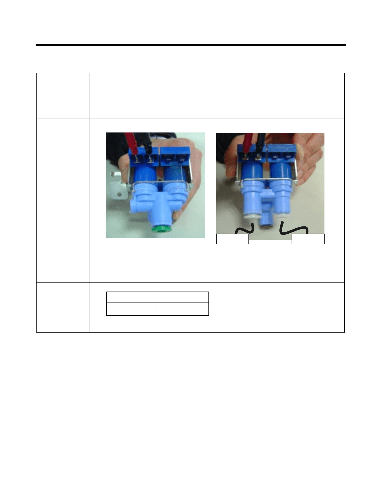
7-9. Water Valve
- first-Water Valve (in machine room)
: supply the water from city water to water filter in refrigerator
- second-Water Valve (in door)
: supply the water from water filter to icemaker and dispenser
Function
How to
Measure
First-water valve
(in machine room)
second-water valve
(in door)
Standard
360 ~ 420 Ω
(1) to (2)
ResultTest Points
Dispense Ice Maker
8-1 REMOVING AND REPLACING REFRIGERATOR DOORS
● Removing Refrigerator Door
ww
CAUTION: Before you begin, unplug the refrigerator. Remove food and bins from doors.
uu
Left Door - Figure 2
2. Open the door. Loosen the top hinge cover screw (1).
Use a flat tip screwdriver to pry back hooks on front underside of the cover (3). Lift up the cover.
3. Disconnect the door switch wire harness (2). Remove the cover.
4. Pull out the tube.
5. Disconnect the three wire harnesses (5). Remove the grounding screw (6).
6. Rotate the hinge lever (7) counterclockwise and remove. Lift the top hinge
(8) free of the hinge lever latch (9).
ww
CAUTION: When lifting the hinge free of latch, be careful that the door does not fall forward.
7. Lift the door up from the middle hinge pin and remove the door.
8. Place the door, inside facing up, down onto a non-scratching surface.
uu
Right Door - Figure 3
1. Open the door. Loosen the top hinge cover screw (1). Lift up the cover (3).
2. Disconnect the door switch wire harness (2). Remove the cover.
3. Disconnect the wire harness (5). Remove the grounding screw (6).
4. Rotate the hinge lever (7) clockwise and remove. Lift the top hinge (8) free of the hinge lever latch (9).
CAUTION: When lifting the hinge free of the latch, be careful that the door does not fall forward.
5. Lift the door up from middle hinge pin (10) and remove the door.
6. Place the door, inside facing up, down onto a non-scratching surface.
8. DISASSEMBLY INSTRUCTIONS
- 53 -
3
1
4
6
2
7
8
9
5
4
1
7
8
3
2
6
5
9
Figure 1
Figure 2 Figure 3

- 54 -
8-2 DOOR
● Door Gasket Removal
1. Remove door frame cover
Starting at the top of cover and working down,
snap the cover out and away from the door.
2. Remove gasket bracket clips
There are two clips on each door. Start the bracket
removal near one of the middle clips.
1) Pull the gasket back to expose the gasket bracket clip
and door frame.
2) Insert a flat tip screwdriver into the seam between the
gasket bracket and the door frame and pry back until
the clips snap out.
3) Continue prying back along the seam until all clips
snap out.
3. Remove gasket
Pull the gasket free from
gasket channel on the three
remaining sides of door.
● Door Gasket Replacement
1. Insert gasket bracket clips
1) Insert the gasket bracket edge beneath the door
frame edge.
2) Turn the upper gasket bracket spring so that the
spring ends are in the door channel.
3) Push in the clip until you hear it snap securely into
place.
4) Push in the remaining clip until you hear it snap
securely into place.
Note: Make sure that no part of the gasket bracket edge
protrudes from beneath the door frame edge.
2. Insert gasket into channel
1) Snap the gasket assembly into the door bracket.
Inserting the Gasket Assembly into the Bracket Door
Frame Cover
Handle
Door
Frame
Gasket
Bracket Clip
Flat Tip
Screwdriver
Gasket
Bracket
Figure 1
Figure 2
Figure 3
Door
Frame
Gasket
Bracket Clip
Spring
IncorrectCorrect
Incorrect
Correct
Figure 4
Figure 5
- 55 -
2) Press the gasket into the channels on the three
remaining sides of door.
3. Replace door frame cover
Starting at the top of the cover and working down, snap
the cover back into door.
.
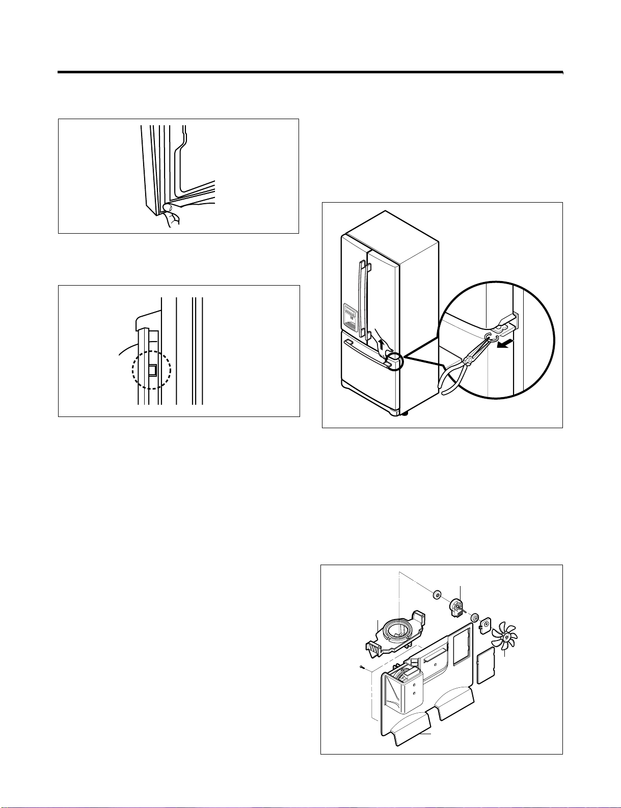
8-3 DOOR ALIGNMENT
If the space between your doors is uneven, follow the
instructions below to align the doors:
1. With one hand, lift up the door you want to raise at the
the middle hinge.
2. With the other hand, use pliers to insert the snap ring as
shown.
3. Insert additional snap rings until the doors are aligned.
(Three snap rings are provided with unit.)
8-4 FAN AND FAN MOTOR (EVAPORATOR)
1. Remove the freezer shelf.
2. Remove the plastic guide for the slides on left side by
unscrewing the phillips head screws.
3. Remove the grille by removing one screw and pulling the
grille forward.
4. Remove the Fan Motor assembly by loosening 2 screws
and disassembling the shroud.
5. Pull out the fan and separate the Fan Motor and Bracket.
Figure 6
Figure 10
Figure 7
GRILLE
FAN MOTOR
FAN
BRACKET
MOTOR
Figure 11
* Ice Fan Scroll Assembly Replacement
1) Remove the plastic guide for the slides on left side by
unscrewing the phillips head screws.
2) Pull the grille forward as shown in the second picture.
3) Disconnect the wire harness of the grille
4) Remove the scroll assembly by loosening 2 screws
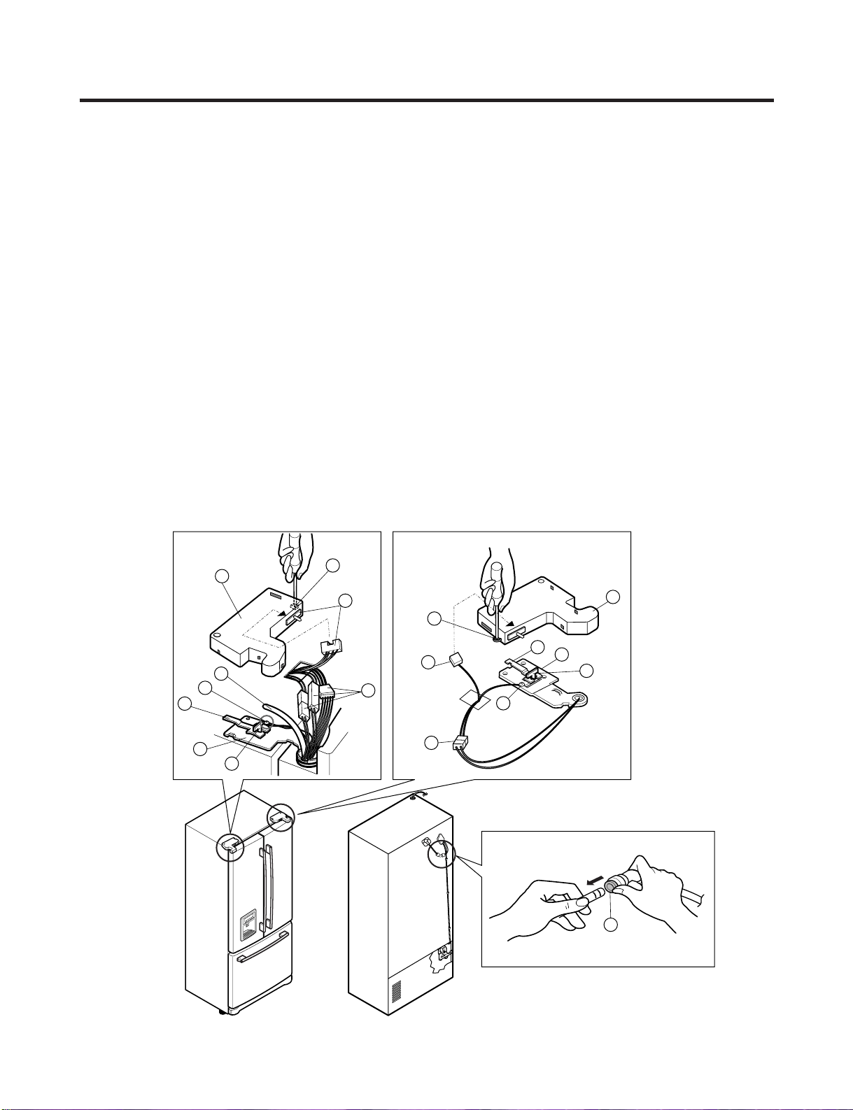
8-5 DEFROST CONTROL ASSEMBLY
The defrost Control assembly consists of the Defrost
Sensor and the FUSE-M.
The Defrost Sensor works to defrost automatically. It is
attached to the metal side of the Evaporator and senses its
temperature. At 72°C, it turns the Defrost Heater off.
Fuse-M is a safety device for preventing overheating of
the Heater when defrosting.
1. Pull out the grille assembly. (Figure 12)
2. Separate the connector with the Defrost Control
assembly and replace the Defrost Control assembly
after cutting the Tie Wrap. (Figure 13)
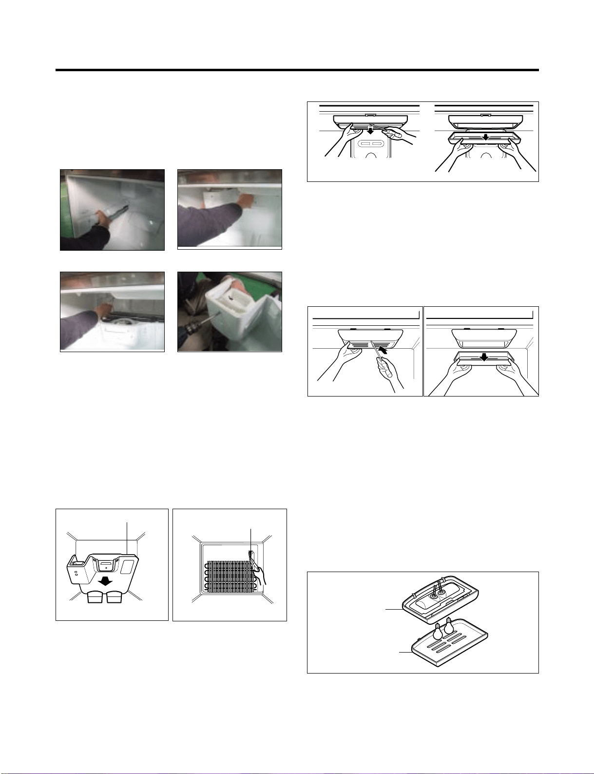
8-6 LAMP
8-6-1 Refrigerator Compartment Lamp
1. Unplug the Refrigerator or disconnect power at the
circuit breaker.
2. If necessary, remove the top shelf or shelves.
3. Using a flat instrument, gently pry the cover loose in the
front as shown. Rotate downward to remove rear tabs.
4. Make sure the bulbs are cool to the touch.
Turn bulbs counterclockwise to remove.
5. Assemble in reverse order by snapping the Lamp Cover
in, engaging the rear tabs followed by the front tabs.
(Max. 60 W-2EA)
8-6-2 Freezer Compartment Lamp
1. Unplug refrigerator power cord form outlet.
2. Using a flat instrument, gently pry the lamp cover
loose in the front as shown. Rotate downward to
remove the rear tabs.
3. Make sure the bulb is cool to the touch. Turn the
bulb counterclockwise to remove.
4. Replace with a new 60-watt appliance bulb.
5. Insert tabs on back of cover into slots in freezer
ceiling. Push cover up to snap front into place.
8-7 CONTROL BOX-REFRIGERATOR
1. First, remove all shelves in the refrigerator, than remove
the Refrigerator control Box by loosening 2 screws.
2. Remove the Refrigerator Control Box by pulling it
downward.
3. Disconnect the lead wire on the right position and
separate the lamp sockets.
- 56 -
GRILLE ASSEMBLY
Figure 12
DEFROST-CONTROL
ASSEMBLY
Figure 13
Figure 14
Figure 15
CONTROL BOX
COVER LAMP
Figure 16
(1) (2)
(3) (4)
8-8 MULTI DUCT
1. Remove the upper and
lower
aps by using a
flat screwdriver, and
remove 2 screws.
(Figure 17)
2. Disconnect the lead wire
on the bottom position.
8-9 MAIN PWB
1) Loosen the 3 screws on
the PCB cover.
2) Remove the PCB cover
3) Disconnect wire harness
and replace the main PCB
in the reverse order of
removal.
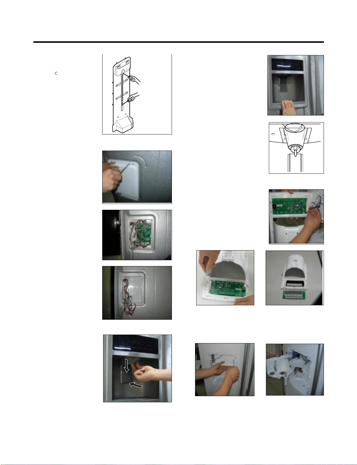
8-10 DISPENSER
1) Disconnect the funnel and
button assembly by
pulling down and forward.
2) Remove display frame
assembly by making a gap
between the display frame
assembly and door
with a flat blade screwdriver
and pulling it forward. The
cover dispenser is attached
with a hook.
ww
CAUTION: When replacing
the dispenser cover in the
reverse order of removal, be
careful that the lead wire does
not come out and the water
tube is not pinched by the
dispenser cover, as shown in
the picture below.
8-11 DISPLAY PCB REPLACEMENT
1) Pull up and out on the dispenser
cover to remove.
2) Follow the steps in the pictures
8-12 FUNNEL REPLACEMENT
1) Pull up and out on the dispenser cover to remove.
2) Disconnect the wire harness.
3) Replace in reverse order.
Figure 17
- 57 -
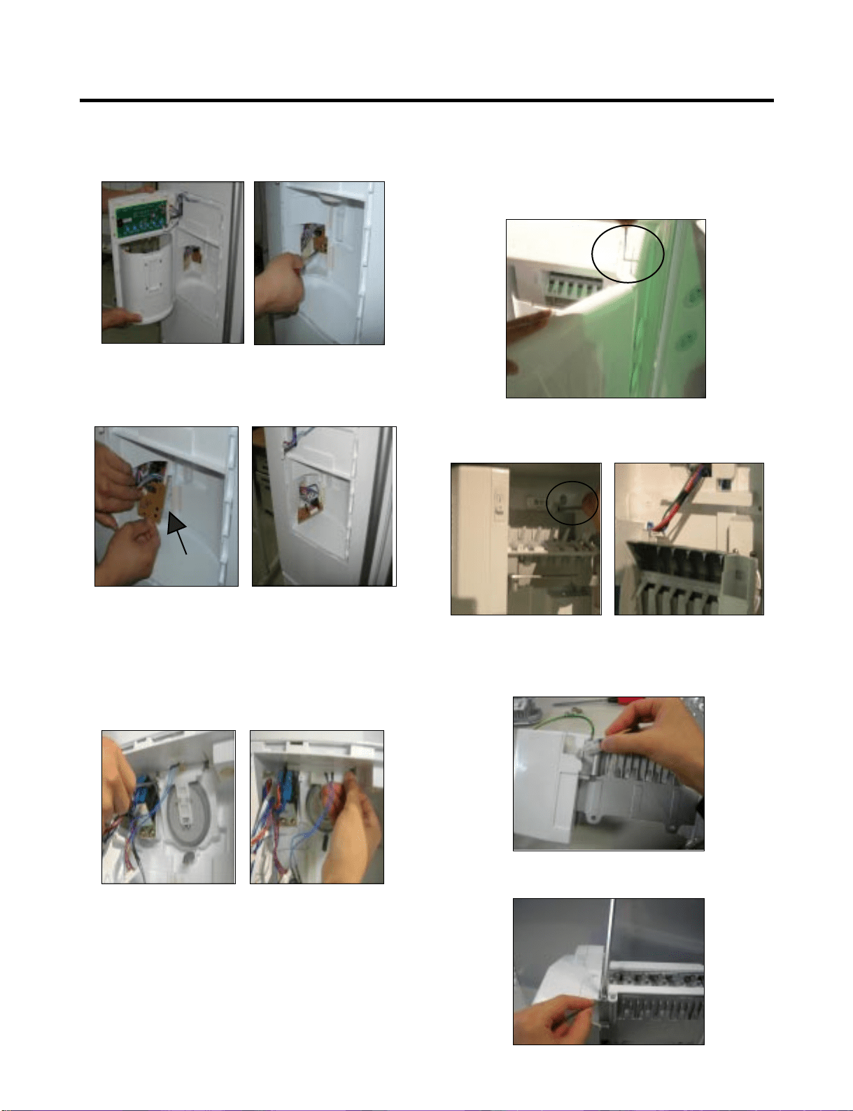
8-13 SUB PWB FOR WORKING DISPENSER
1) Loosen the screw on the sub PCB.
2) Pull the sub PCB down.
3) Disconnect the wire harness and replace the sub PCB
in the reverse order of removal.
8-14 DUCT DOOR REPLACEMENT
1) Pull up and out on the dispenser cover to remove.
2) Disconnect the wire harness.
3) Remove the funnel
4) Replace in reverse order.
8-15 ICE CORNER DOOR REPLACEMENT
1) Loosen the front screw as shown in the picture.
2) Lift up the hinge with one hand.
3) Pull out the Ice Corner Door with the other hand.
8-16 ICEMAKER ASSEMBLY
1) Loosen two screws as shown in the first picture.
2) Disconnect the wire harness and ground screw replace
theIcemaker assembly in the reverse order of removal.
3) Remove the ground connection screw.
hinge
- 58 -
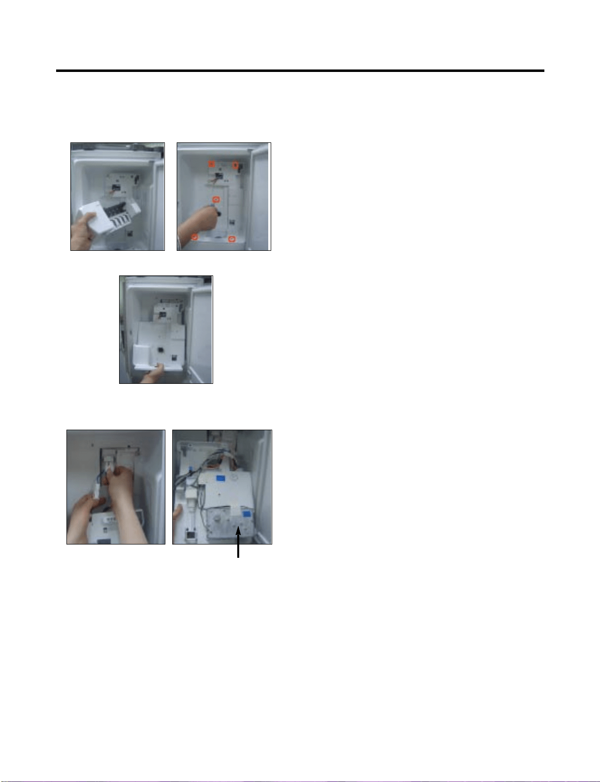
8-17 AUGER MOTOR COVER
1) After removing the icemaker remove the (5) stainless
screws holding the auger motor cover, shown in the
picutres below.
2) Grip the bottom of the motor cover assembly and pull out it.
3) Disconnect the wire harness of the motor cover
assembly. There is a auger motor on the back, as
shown in the picture.
Auger Motor
- 59 -
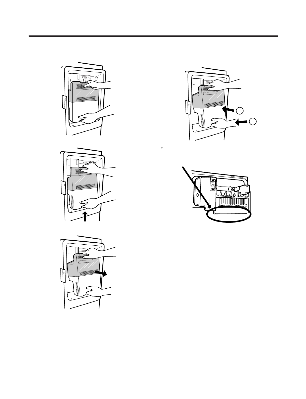
8-18 HOW TO REMOVE THE DOOR ICE BIN
1) Grip the handles, as shown in the picture.
2) Lift the lower part slightly.
3) Take the ice bin out slowly.
8-19 HOW TO INSERT THE DOOR ICE BIN
1) Insert the Ice Bin, slightly tilting it to avoid touching the
icemaker. particularly the feeler arm lever.
Insert the ice bucket carefully avoid contacing the
automatic shut off arm.
- 60 -
1
2
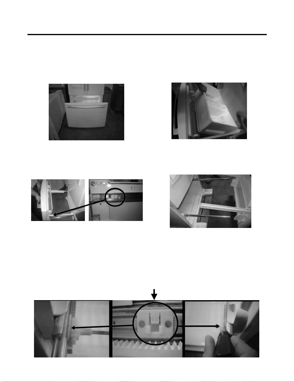
8-20 HOW TO REMOVE AND REINSTALL THE PULLOUT DRAWER
8-20-1 Follow Steps to Remove
Step 1) Open the freezer door.
Step 3) Remove the two screws from the guide rails (one
from each side).
Step 2) Remove the lower basket.
Step 4) Lift the freezer door up to unhook it from the rail
support and remove.
Pull both rails to full extension.
Step 5) First: Remove the gear from the left side first by releasing the tab behind the gear, place a screwdriver between the
gear and the tab and pull up on the gear.
Second Remove the center rail.
Third Remove the gear from the right side by following the same steps for the left side.
NOTE: THIS TAB MUST BE PUSHED IN TO RELEASE THE GEAR.
- 61 -
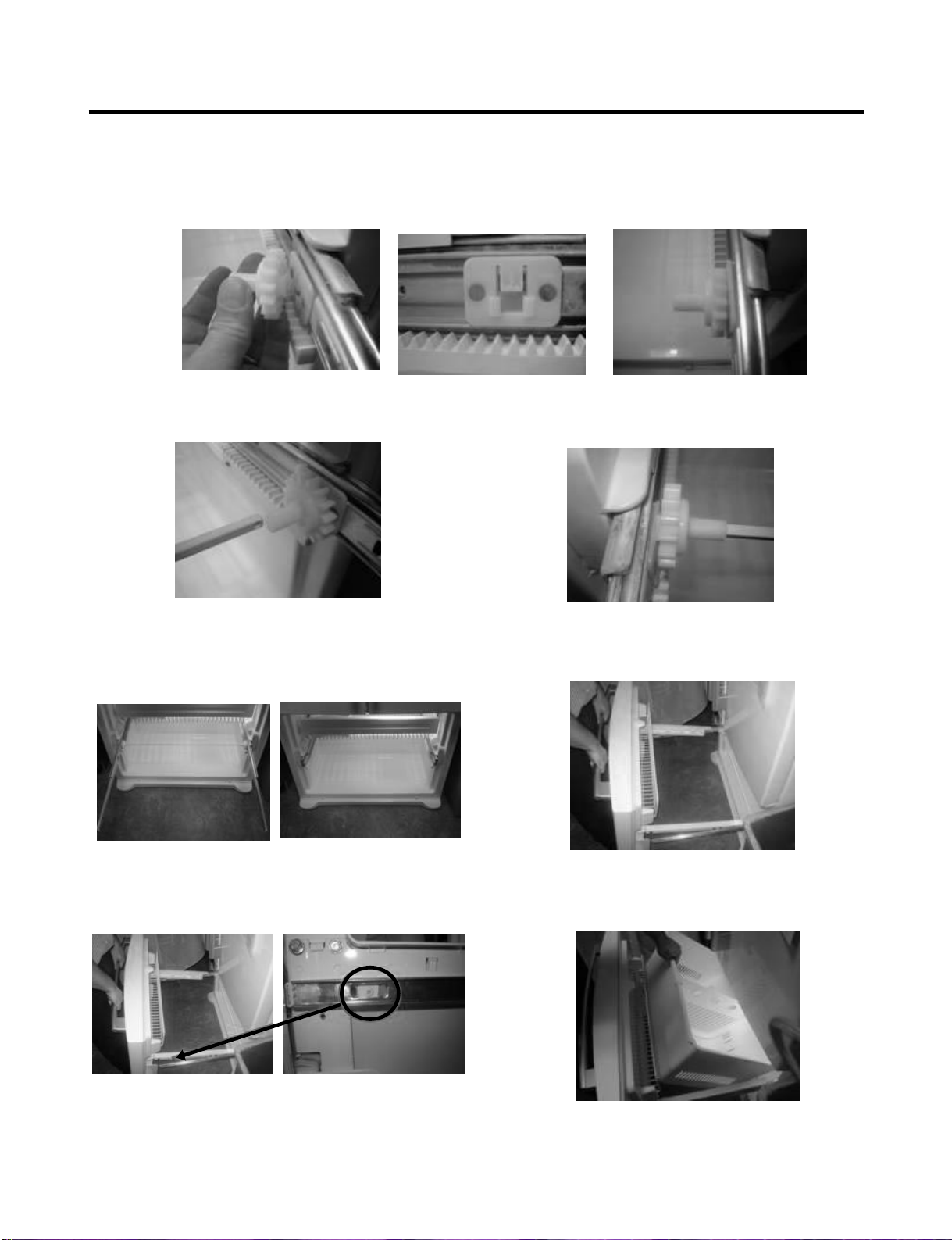
8-20-2 Follow Steps to Reinstall
Step 1) Reinstall the right side gear into the clip.
Step 2) Insert the rail into the right side gear. Gears do not
need to be perpendicular to each other.
Step 4) The rail system will align itself by pushing the rails
all the way into the freezer section.
Pull the rails back out to full extension.
Step 6) Reinstall the two screws into the guide rails
(one from each side).
Step 3) Insert the rail into the left side gear, and insert the
gear into the clip.
Step 5) Reinstall the freezer door by inserting the rail tabs
into the guide rail.
Step 7) Reinstall the lower basket, and close the freezer
door.
- 62 -
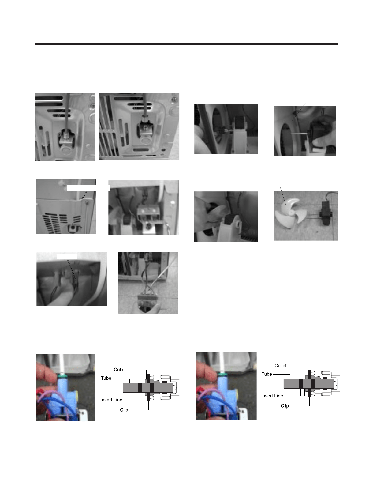
8-21. WATER VALVE DISASSEMBLY METHOD
1) Turn off the water. Then separate the water line from the
valve.
2). Separate the mechanical cover and valve screw.
3) Separate the housing and pull out the valve.
4) Lay a dry towel on the floor and get ready to spill water
from the water filter. Pull out the cilp. Then press te the
collet to separate the tube from the connector and pour
out the water until emptied.
8-22. FAN AND FAN MOTOR DISASSEMBLY
METHOD
1) Using a short screwdriver, loosen one SCREW in
DRAIN PIPE ASSEMBLY and one connected to the
MOTOR COVER.
2) Pull and separate the FAN ASSEMBLY and MOTOR
turning counterclockwise based on the MOTOR SHAFT.
Reassembly is in the reverse order of the disassembly and
take special care for the following details.
1. Be careful not to bend the tube during assembly.
2. Press the WATER DISPENSER button until water pours
out and check for leakage in the CONNECTOR TUBE (It
differs by the water pressure but usually takes about 2
minutes for the wayer to drain.)
Mechanical Cover
Housing
→
→
MOTOR COVER
FAN ASSEMBLY MOTOR
- 63 -
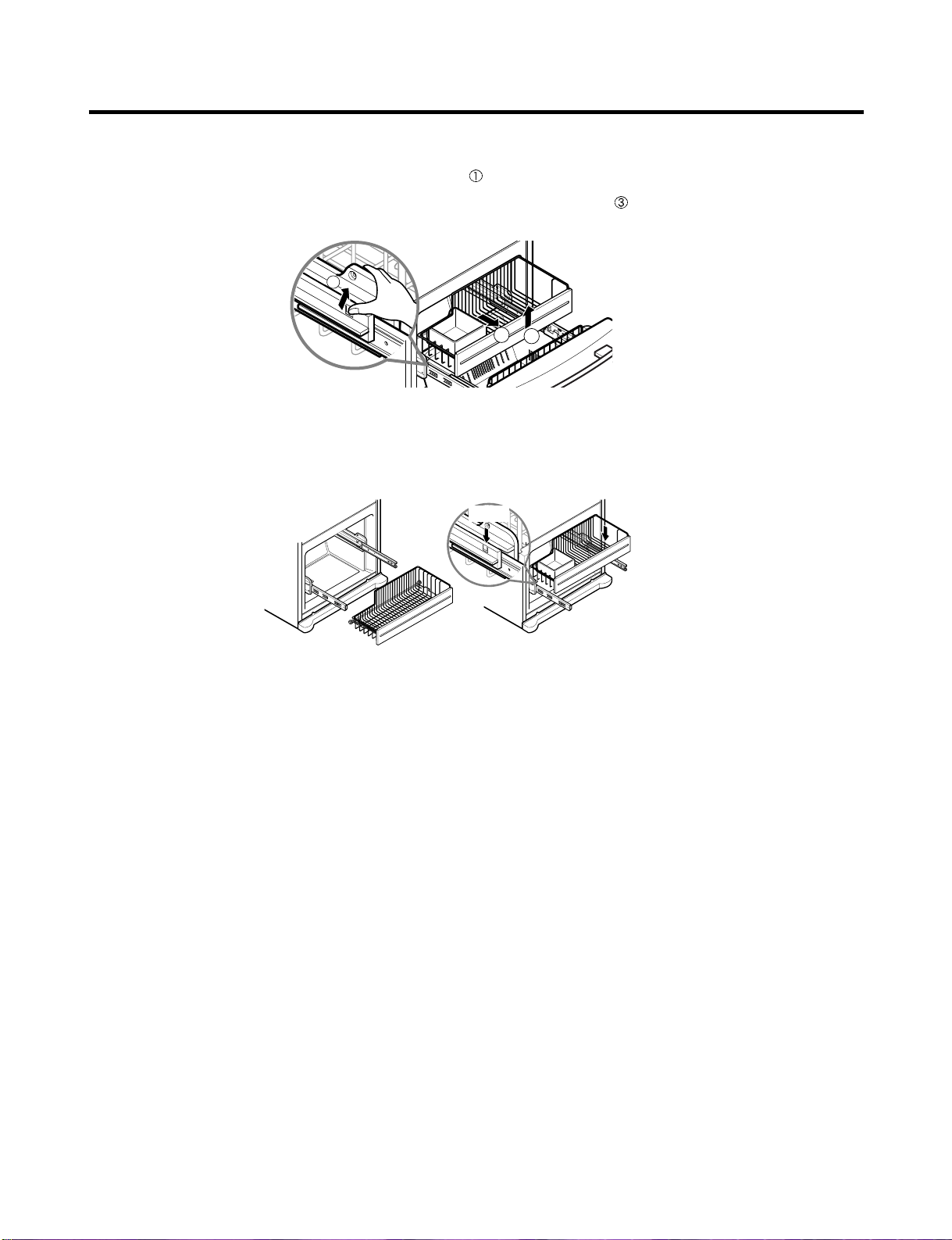
8-23 PULL OUT DRAWER
To separate the drawer, push the front left and right hooks in direction to pull up and remove.
Then gently lift the gear part of rear left and right side of the drawer and pull it out in
direction.
To install, reposition the gear part of rear left and right side of the drawer after pulling out both rails as much as possible,
and gently push down both left and right side while checking the hook on the front part.
2
3
1
Hook
- 64 -
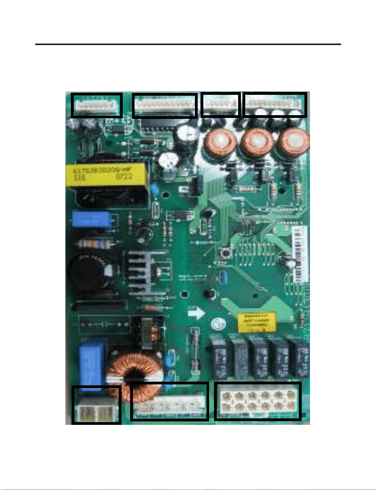
9-1. Main PCB Assembly
6871JB1431 (by July 2007)
CON1
CON2
CON3
CON4CON5
CON6
CON7
9. PCB ASSEMBLY
- 65 -
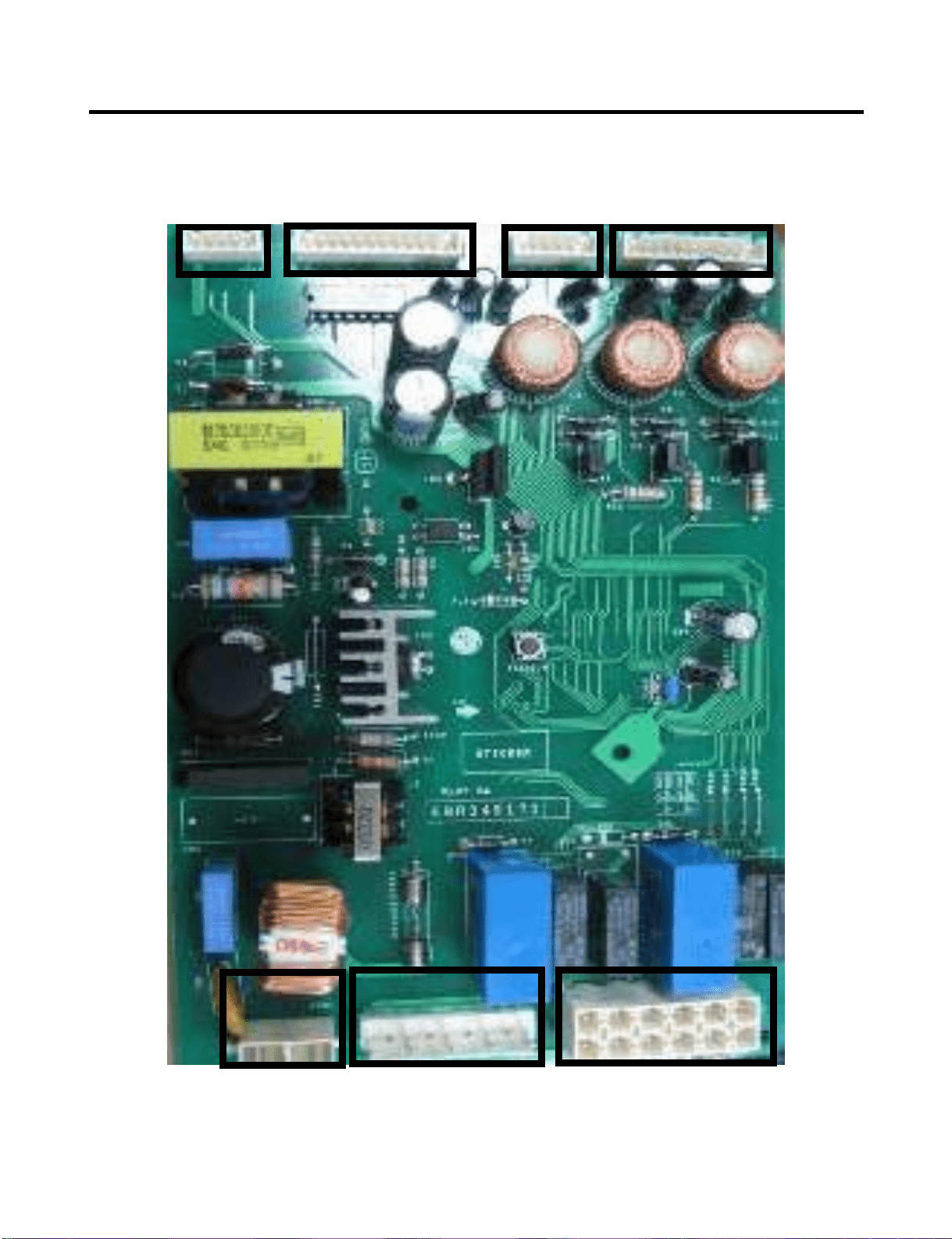
EBR34917102 (from Aug 2007)
- 66 -
CON4CON5
CON6
CON7
CON1
CON2
CON3
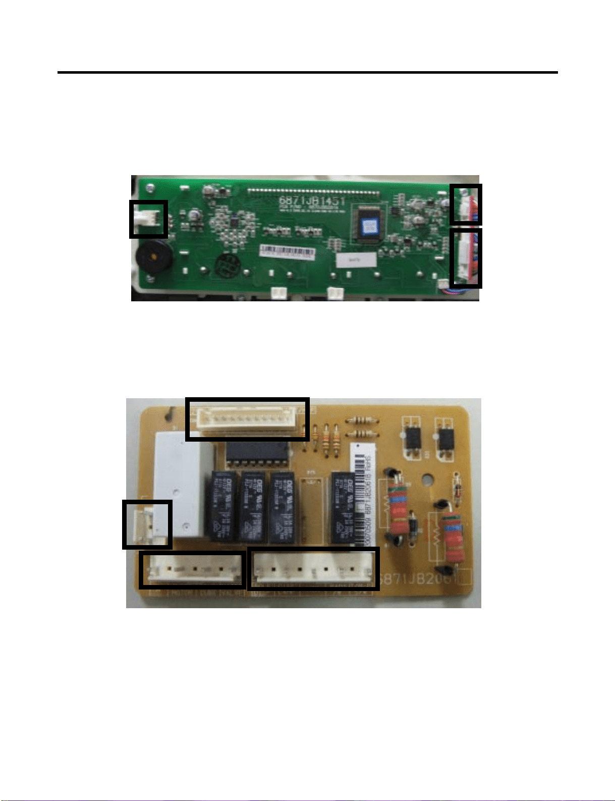
- 67 -
9-2. Display and Dispenser Drive PCB Assembly
Display PCB
Dispenser PWB
CON103
CON101
CON102
CON4
CON3
CON2
CON1
CON4
616F
S31
S31
S31
S32
623B
616G
616H
627A
616D
617A
619A
619B
619D
603B
625A
623B
616G
616H
603A
616F
® Registered Trademark /
TM
Trademark /
SM
Service Mark of Sears, Roebuck and Co.
® Marca Registrada /
TM
Marca de Fábrica /
SM
Marca de Servicio de Sears, Roebuck and Co.
MC
Marque de commerce /
MD
Marque déposée de Sears, Roebuck and Co. © Sears, Roebuck and Co.
Get it fixed, at your home or ours!
Your Home
For repair – in your home – of all major brand appliances,
lawn and garden equipment, or heating and cooling systems,
no matter who made it, no matter who sold it!
For the replacement parts, accessories and
owner’s manuals that you need to do-it-yourself.
For Sears professional installation of home appliances
and items like garage door openers and water heaters.
1-800-4-MY-HOME
®
(1-800-469-4663)
Call anytime, day or night
(U.S.A. and Canada)
www.sears.com www.sears.ca
Our Home
For repair of carry-in items like vacuums, lawn equipment,
and electronics, call or go on-line for the location of your nearest
Sears Parts & Repair Center.
1-800-488-1222
Call anytime, day or night (U.S.A. only)
www.sears.com
To purchase a protection agreement (U.S.A.)
or maintenance agreement (Canada) on a product serviced by Sears:
1-800-827-6655 (U.S.A.) 1-800-361-6665 (Canada)
Para pedir servicio de reparación
a domicilio, y para ordenar piezas:
1-888-SU-HOGAR
SM
(1-888-784-6427)
Au Canada pour service en français:
1-800-LE-FOYER
SM
(1-888-533-6937)
www.sears.ca
The model number of your
refrigerator is found on the serial
plate inside.
All repair parts listed are available
for immediate purchase or special
order when you visit your nearest
Sears Service Center, or the
Service Department at most Sears
stores. To order parts by phone,
call the toll free parts number
listed to the left.
When requesting service or
ordering parts, always provide the
following information:
•Product Type •Part Number
•Model Number •Part Description
MODELS No.
795.77562600
795.77569600
795.77564600
795.77563600
795.77572600
795.77579600
795.77573600
To call
Toll Free
For Parts:
1-800-366-PART
(1-800-366-7278)
For Service:
1-800-4-MY-HOME
(1-800-469-4663)
REPAIR
PARTS
LIST
Sears, Roebuck and Co., Hoffman Estates, IL 60179 U.S.A.
Last Revision: JJNE. 7. 2007
619E
- 1 -
Part No. 3840JL8042A
V
ALVE & WATER TUBE PARTS
CAUTION: Use the part number to order part, not the location number.
LOC No. 775** Description
603A 4004JA3002A Clip
603D 4930JA3091A Holder,Bracket
616D 5210JA3005L Tube,Plastic
616F 5210JA3004U Tube,Plastic
616G 5210JA3005W Tube,Plastic
616H 4932JA3009A Connector,Tube
617A 4970JA3004N Spring
619A 5221JA2011J Valve,Water
619B 5220JB2008A Valve,Water
619D 6877JB3036K Drawing,Assembly
619E 6877JB3036M Drawing,Assembly
623B 5006JJ2009A Cap,Cover
625A 3550JA2184B Cover,Tube
627A 4930JA3054A Holder,PipeS31
S31 4J00415D Screw,Customized
S32 4000W4A003A Screw,Customized
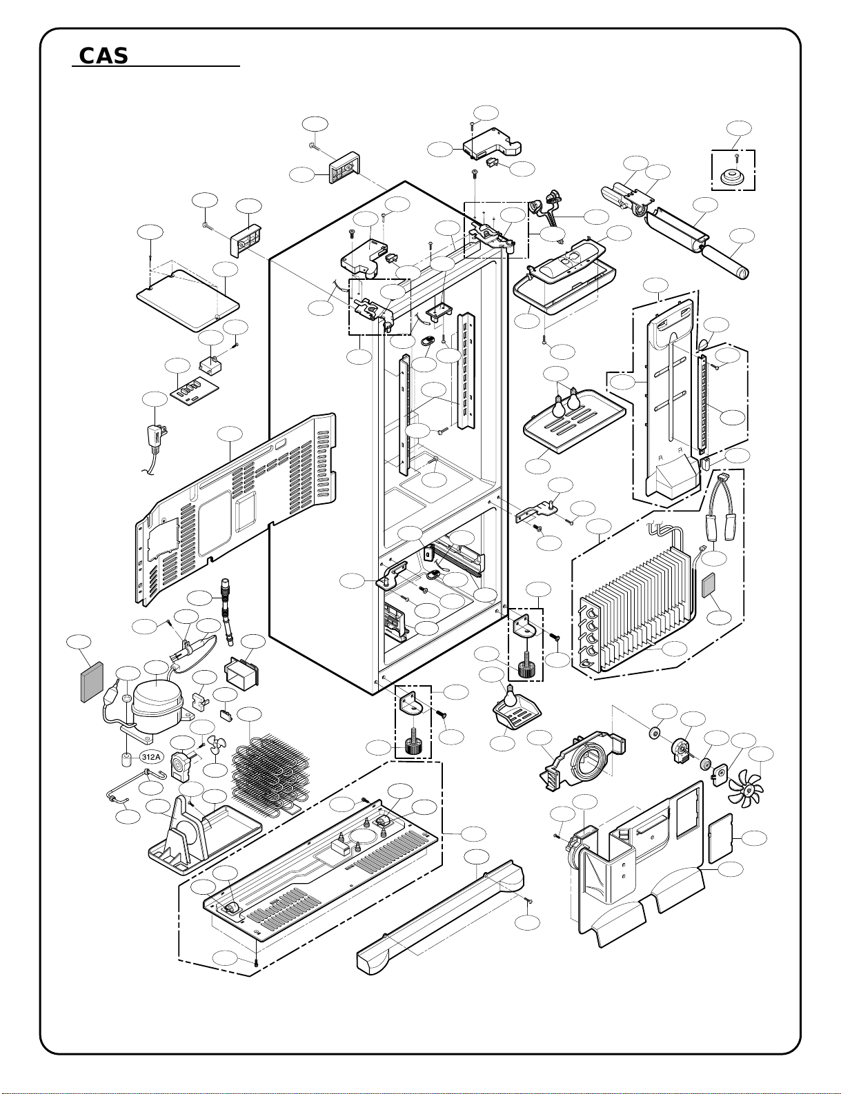
- 2 -
312A
CASE P
ARTS
CAUTION: Use the part number to order part, not the position number.
313A
S01
103B
103A
S02
411A
500A
410G
S01
S02
402A
207C
207A
S03
501F
S03
207B
610B
610B
406D
624C
624D
626A
402A
603B
624A
283B
B02
301A
S14
S10
610A
145B
S12
S11
158A
282G
145A
S08
282F
409B
120B
S11
503D
409D
410A
158B
409B
106A
408A
316B
400A
B03
262H
249D
406B
S14
S03
610A
249C
315C
315A
405A
283B
262B
610C
404A
405F
407A
S16
315B
103C
S17
332C
135D
329A
405B
405C
106A
B04
S15
315B
315C
329C
B03
314A
316A
S18
318A
317A
304A
105A
303B
300A
420A
S20
323B
319A
S19
319C
327A
310B
303C
120A
271A
271B
271C
271D

- 3 -
CAUTION: Use the part number to order part, not the position number.
CASE PARTS
LOC No. 775*3(ST) 775*2(SW) 775*9(WB) 775*4(BI) Description
103A 3650JA2061X 3650JA2061B 3650JA2113N 3650JA2061V Handle,Rear
103B 3650JA2061W 3650JA2061A 3650JA2113P 3650JA2061U Handle,Rear
103C 3550JJ0008L 3550JJ0008A 3550JJ0008C 3550JJ0008B Cover,Lower
105A 5251JA3003B 5251JA3003B 5251JA3003B 5251JA3003B Tube Assembly,Drain
106A 4779JJ2001B 4779JJ2001B 4779JJ2001B 4779JJ2001B Leg Assembly,Adjust
120B 5208JA1156A 5208JA1156A 5208JA1156A 5208JA1156A Duct,Multi
135D 3551JJ2028A 3551JJ2028A 3551JJ2028A 3551JJ2028A Cover Assembly,Grille Fan
145A 4930JA2080C 4930JA2080C 4930JA2080C 4930JA2080C Holder,Shelf
145B 4930JA2081C 4930JA2081C 4930JA2081C 4930JA2081C Holder,Shelf
158A 3550JJ1070B 3550JJ1070B 3550JJ1070B 3550JJ1070B Cover,Lamp
158B 3550JA1386B 3550JA1386B 3550JA1386B 3550JA1386B Cover,Lamp
207A 3550JJ1097Q 3550JJ1097A 3550JJ1097E 3550JJ1097C Cover,Hinge
207B 3550JJ1097R 3550JJ1097B 3550JJz097F 3550JJ1097D Cover,Hinge
207C 3806JA2146E 3806JA2146A 3806JA2146C 3806JA2146D Decor Assembly,Case
249C 4930JA1066A 4930JA1066A 4930JA1066A 4930JA1066A Holder,Rail
249D 4930JA1066B 4930JA1066B 4930JA1066B 4930JA1066B Holder,Rail
262B 4775JJ2017P 4775JJ2017B 4775JJ2017F 4775JJ2017K Hinge Assembly,Center
262H 4775JJ2017R 4775JJ2017D 4775JJ207H 4775JJ2017M Hinge Assembly,Center
271A 4775JJ2014B 4775JJ2014B 4775JJ2014B 4775JJ2014B Hinge Assembly,Upper
271B 4510JA3004A 4510JA3004A 4510JA3004A 4510JA3004A Lever,Hinge
271C 4775JJ2014A 4775JJ2014A 4775JJ2014A 4775JJ2014A Hinge Assembly,Upper
282F 3806JL1037A 3806JL1037A 3806JL1037A 3806JL1037A Decor,Duct
282G 5006JA3111A 5006JA3111A 5006JA3111A 5006JA3111A Cap,Duct
283B 4774JJ3002A 4774JJ3002A 4774JJ3002A 4774JJ3002A Hinge,Lower
300A TCA31748001 TCA31748001 TCA3174800 1 TCA31748001 Compressor,Set Assembly
301A 5421JJ1003B 5421JJ1003B 5421JJ1003B 5421JJ1003B Evaporator Assembly
303A EBG31940225 EBG31940225 EBG31940225 EBG31940225 Thermistor Assembly,PTC
303B 6748C-0004D 6748C-0004D 6748C-0004D 6748C-0004D Thermistor Assembly,PTC
303C 6750C-0004R 6750C-0004R 6750C-0004R 6750C-0004R Overload Protect
303D 6877JB2051F 6877JB2051F 6877JB205 1 F 6877JB2051F Drawing,Assembly
304A 3550JA2042C 3550JA2042C 3550JA2042C 3550JA2042C Cover,PTC
310B 4J00977N 4J00977N 4J00977N 4J00977N Pipe,Compressor Sealing
312A 5040JA3071A 5040JA3071A 5040JA3071A 5040JA3071A Damper,Compressor
313A 3551JJ2018A 3551JJ2018A 3551JJ2018A 3551JJ2018A Cover Assembly,Machinery(Rear)
314A 4620JA3015A 4620JA3015A 4620JA3015A 4620JA3015A Stopper,Compressor
315A 3103JJ1001H 3103JJ1001H 3103JJ1001H 3103JJ1001H Base Assembly,Compressor
315B 4580JJ3001A 4580JJ3001A 4580JJ3001A 4580JJ3001A Roller
315C 1PZZJA3013B 1 PZZJA3013B 1PZZJA3013B 1PZZJA3013B Pin,Common
316A 5072JA3003F 5072JA3003F 5072JA3003F 5072JA3003F Damper,Noise
316B 5072JA3003B 5072JA3003B 5072JA3003B 5072JA3003B Damper,Noise
317A 5851JA2008U 5851JA2008U 5851JA2008U 5851JA2008U Drier Assembly
318A 4930JA3034A 4930JA3034A 4930JA3034A 4930JA3034A Holder,Drier
319A 3390JA0040A 3390JA0040A 3390JA0040A 3390JA0040A Tray,Drip
319C 4974JJ1036A 4974JJ1036A 4974JJ1036A 4974JJ1036A Guide,Fan
323B 5403JJ1004B 5403JJ1004B 5403JJ1004B 5403JJ1004B Condenser Assembly,Wire
327A 4J03020A 4J03020A 4J03020A 4J03020A Damper,Pipe
329A 5901JA1021A 5901JA1021A 5901JA1021A 5901JA1021A Fan Assembly
329C 5901JA1013A 5901JA1013A 5901JA1013A 5901JA1013A Fan Assembly
332C AEB34270101 AEB34270101 AEB34270101 AEB34270101 Grille Assembly,Fan
400A 6615JB2005H 6615JB2005H 6615JB2005H 6615JB2005H Controller Assembly
402A 6600JB3007B 6600JB3007A 6600JB3007E 6600JB3007A Switch,Push Button
402C 6600JB3001E 6600JB3001E 6600JB3001E 6600JB3001E Switch,Micro
404A 4681JK1004E 4681JK1004E 4681JK1004E 4681JK1004E Motor,DC
405B 4810JJ2005A 4810JJ2005A 4810JJ2005A48 10JJ2005A Bracket,Motor
405C 5040JA2009B 5040JA2009B 5040JA2009B 5040JA2009B Damper,,Motor Support
405F 5040JA2004B 5040JA2004B 5040JA2004B 5040JA2004B Damper,Motor Support
406B 6600JB1010A 6600JB1010A 6600JB1010A 6600JB1010A Switch,Push B utton
- 4 -
CAUTION: Use the part number to order part, not the position number.
CASE PARTS
LOC No. 775*3(ST) 775*2(SW) 775*9(WB) 775*4(BI) Description
406D 4931JA3006A 4931JA3006A 4931JA3006A 4931JA3006A Holder Assembly, Gasket
407A 5209JA1044A 5209JA1044A 5209JA1044A 5209JA1044A Duet Assembly, Connector
407B 4810JJ0003A 4810JJ0003A 4810JJ0003A 4810JJ0003A Bracket,Motor
408A 5300JK1005D 5300JK1005D 5300JK1005D 5300JK1005D Heater,Sheath
409B 6912JB2004K 6912JB2004K 6912JB2004K 6912JB2004K LAMP,[INCANDESCENT]
409D 3034JA1009A 3034JA1009A 3034JA1009A 3034JA1009A Reflector,Lamp
410A 6621JK2003B 6621JK2003B 6621JK2003B 6621JK2003B
Drawing,Assembly
0CZZJB2014B 0CZZJB2014B 0CZZJB2014B 0CZZJB2014B
410G (*)0CZZJB2012H (*)0CZZJB2012H (*)0CZZJB2012H (*)0CZZJB2012H
Capacitor, Film, Box
(*)0CZZJB2012K (*)0CZZJB2012K (*)0CZZJB2012K (*)0CZZJB2012K
410H *J513-00012P *J513-00012P *J513-00012P *J513-00012P Capacitor, Film, CYL
410J *3111JB1017J *3111JB1017J *3111JB1017J *3111JB1017J Case Assembly, PCB
411A 6411JB1042L 6411JB1042L 6411JB1042L 6411JB1042L POWER CORD ASSEMBLY
420A 4681JB1029D 4681JB1029D 4681JB1029D 4681JB1029D Motor,Unclassified
500A EBR34917104 EBR34917104 EBR34917104 EBR34917104 PCB Assembly,Main
501F 3551JA2144C 3551JA2144C 3551JA2144C 3551JA2144C Cover Assembly,PCB
503D 3110JJ1014A 3110JJ1014A 3110JJ1014A 3110JJ1014A Case,Lamp
603B 4931JA3005B 4931JA3005B 4931JA3005B 4931JA3005B Holder Assembly, Bracket
610A 3550JA2247A 3550JA2247A 3550JA2247A 3550JA2247A Cover,Sensor
610B 6500JB2001B 6500JB2001B 6500JB2001B 6500JB2001B SENSOR
610C 6500JB2002B 6500JB2002B 6500JB2002B 6500JB2002B SENSOR
624A 5231JA2006A 5231JA2006A 5231JA2006A 5231JA2006A Filter Assembly,Water
624C 3550JD1128B 3550JD1128B 3550JD1128B 3550JD1128B Cover,Filter
624D 5230JA2003A 5230JA2003A 5230JA2003A 5230JA2003A Filter,Head
626A 3550JA2279A 3550JA2279A 3550JA2279A 3550JA2279A Cover, Filter
B02 1STZJA3004Q 1STZJA3004Q 1STZJA3004D 1STZJA3004Q Screw,Customzied
B03 1STZJA3004F 1STZJA3004F 1STZJA3004F 1STZJA3004F Screw,Customzied
B04 1BZZJA2002A 1BZZJA2002A 1BZZJA2002A 1BZZJA2002A Bolt, Common
S01 4J00415D 4J00415D 4J00415D 4J00415D Screw,Customzied
S02 4J00415D 4J00415D 4J00415D 4J00415D Screw,Customzied
S03 4J01424B 4J01424B 4J01424B 4J01424B Screw,Customzied
S08 1SZZJJ3005E 1SZZJJ3005E 1SZZJJ3005E 1SZZJJ3005E Screw,Customzied
S09 4J00415D 4J00415D 4J00415D 4J00415D Screw,Customzied
S10 1SBZJA3004L 1SBZJA3004L 1SBZJA3004L 1SBZJA3004L Screw,Customzied
S11 3J05696W 3J05696W 3J05696W 3J05696W Screw,Customzied
S13 1SZZJJ3005E 1SZZJJ3005E 1SZZJJ3005E 1SZZJJ3005E Screw,Customzied
S14 1SZZJJ3010D 1SZZJJ3010D 1SZZJJ3010B 1SZZJJ3010D Screw,Customzied
S15 4000W4A003A 4000W4A003A 4000W4A003A 4000W4A003A Screw,Customzied
S16 3J05696W 3J05696W 3J05696W 3J05696W Screw,Customzied
S17 1SZZJA3005H 1SZZJA3005H 1SZZJA3005H 1SZZJA3005H Screw,Customzied
S18 4J00415D 4J00415D 4J00415D 4J00415D Screw,Customzied
S19 4J00415D 4J00415D 4J00415D 4J00415D Screw,Customzied
S20 1SZZJA3016A 1SZZJA3016A 1SZZJA3016A 1SZZJA3016A Screw,Customzied
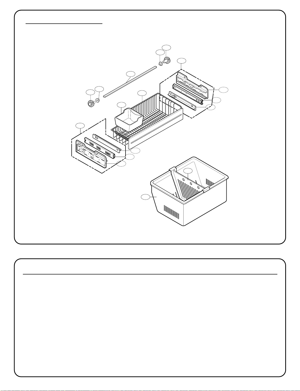
- 5 -
145C
136B
145F
136A
237C
131A
250C
250D
250E
250D
250C
CAUTION: Use the part number to order part, not the position number.
LOC No. 775*3(ST) 775*2(SW) 775*9(WB) 775*4(BI) Description
131A 5074JA2004A 5074JA2004A 5074JA2004A 5074JA2004A Bucket,Ice
136A 3390JJ1072A 3390JJ1072A 3390JJ1072A 3390JJ1072A Tray,Drawer
136B 3391JA2054D 3391JA2054D 3391JA2054D 3391JA2054D Tray Assembly,Drawer
145C 4975JA1040F 4975JA1040F 4975JA1040F 4975JA1040F Guide Assembly,Rail
145F 4975JA1040E 4975JA1040E 4975JA1040E 4975JA1040E Guide Assembly,Rail
237C 4974JJ1031A 4974JJ1031A 4974JJ1031A 4974JJ1031A Guide,Drawer
250C 4470JA2008A 4470JA2008A 4470JA2008A 4470JA2008A Gear,Ice
250D 5006JA2069A 5006JA2069A 5006JA2069A 5006JA2069A Cap,Cover
250E MAK36519001 MAK36519001 MAK36519001 MAK36519001 Bar
FREEZER P
ARTS
CAUTION: Use the part number to order part, not the position number.
145G
145J
145K
145M
145J
145H
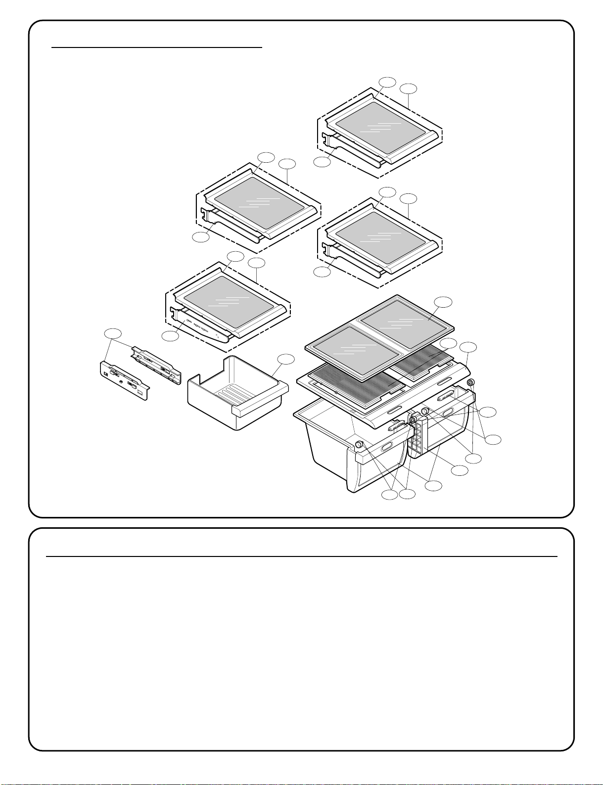
- 6 -
151D
151D
151F
151F
154A
151C
167B
141D
141B
140B
140C
140A
140D
141B
141C
141A
141B
141C
141A
141B
141C
141A
151A
154C
REFRIGERA
TOR PARTS
CAUTION: Use the part number to order part, not the position number.
CAUTION: Use the part number to order part, not the position number.
LOC No. 775*3(ST) 775*2(SW) 775*9(WB) 775*4(BI) Description
140A 5027JJ2014J 5027JJ2014J 5027JJ2014J 5027JJ2014J Shelf Assembly,Refrigerator
140B 5027JJ2012D 5027JJ2012D 5027JJ2012D 5027JJ2012D Shelf Assembly,Net
140C 4975JA2028A 4975JA2028A 4975JA2028A 4975JA2028A Guide Assembly,Rail
140D 3391JA2055C 3391JA2055C 3391JA2055C 3391JA2055C Tray Assembly,Meat
141A 5027JJ2014D 5027JJ2014D 5027JJ2014D 5027JJ2014D Shelf Assembly,Refrigerator
141B 5026JJ1050B 5026JJ1050B 5026JJ1050B 5026JJ1050B Shelf,Refrigerator
141C 5027JJ2012F 5027JJ2012F 5027JJ2012F 5027JJ2012F Shelf Assembly,Net
141D 4890JL1012A 4890JL1012A 4890JL1012A 4890JL1012A Cover,Glass
151A 3391JJ2014C 3391JJ2014C 3391JJ2014C 3391JJ2014C Tray Assembly,Vegetable
151C 4940JA2026C 4940JA2026C 4940JA2026C 4940JA2026C Knob,Shutter
151D 4850JA3042A 4850JA3042A 4850JA3042A 4850JA3042A Roller
151F 1SZZJA3011B 1SZZJA3011B 1SZZJA3011B 1SZZJA3011B Screw, Customized
154A 3550JD1129A 3550JD1129A 3550JD1129A 3550JD1129A Cover,TV
154C 4980JA2092A 4980JA2092A 4980JA2092A 4980JA2092A Supporter. Cover TV
167B 3550JJ1069A 3550JJ1069A 3550JJ1069A 3550JJ1069A Cover,Magic Room
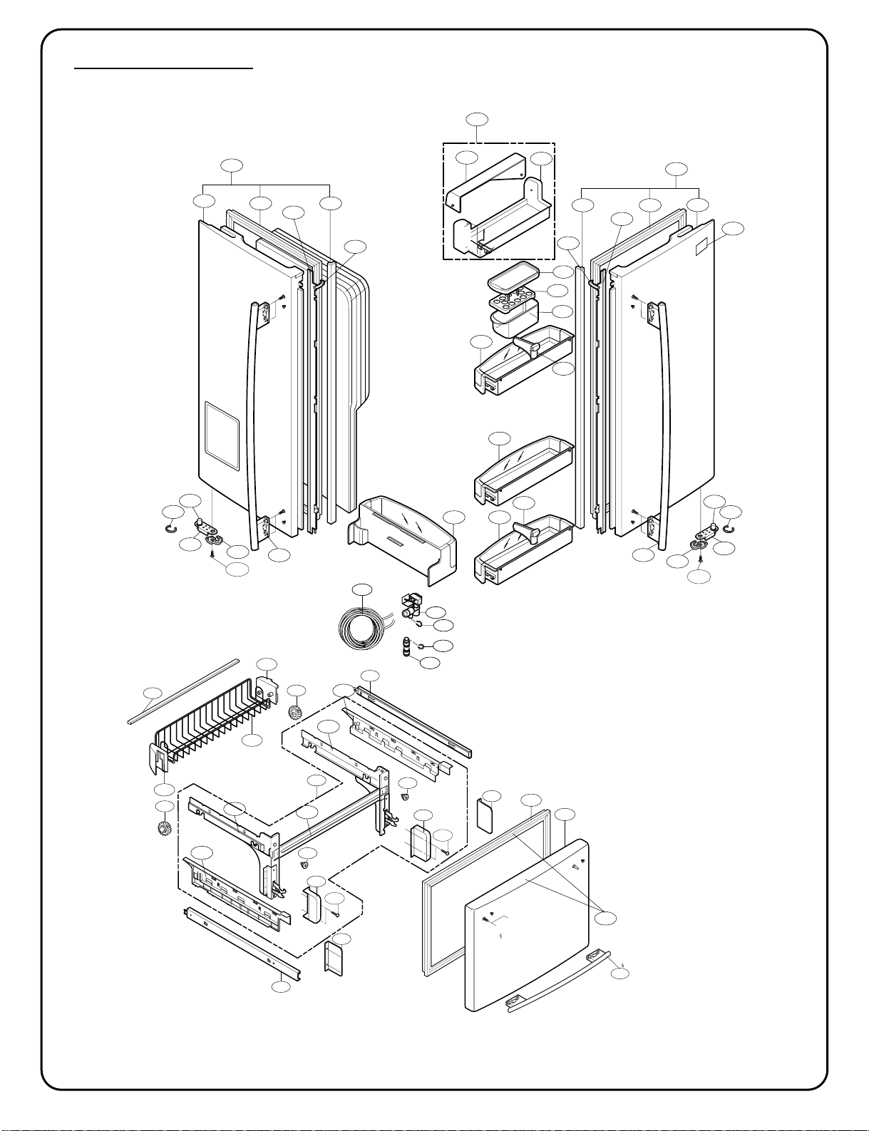
- 7 -
233A233D
231A
233B 233C
231B
241D
237A
241E
241F
230B
241A
241B
241C
243A
212G
230A
234A
234C
S25
262C
243C
243A
243C
243B
262C
S25
147C
147B
147A
237A
619B
603D
616J
603C
615A
243B
234B
234D
DOOR P
ARTS
CAUTION: Use the part number to order part, not the position number.
▲ Only for the service
212D
241G
244A
244A
203A
201A
250A
250B
249F
S34
281E
281G
249E
S34
281D
281G
249S
281F
281F
250B
205C
205B
205A
249P
249Q
249G
249H
249R
200A
- 8 -
DOOR P
ARTS
CAUTION: Use the part number to order part, not the position number.
LOCNo. 775*3(ST) 775*2(SW) 775*9(WB) 775*4(BI) Description
146A J469-00030A J469-00030A J469-00030A J469-00030A Rack (7757* only)
147A 5074JJ1016A 5074JJ1016A 5074JJ1016A 5074JJ1016A Bucket,Dairy
147B 3390JJ1082A 3390JJ1082A 3390JJ1082A 3390JJ1082A Tray,Egg
147C 3550JJ1084A 3550JJ1084A 3550JJ1084A 3550JJ1084A Cover,Bucket
200A 3581JA8820K 3581JA8820N 3581JA8820L 3581JA8820M Door Assembly,Freezer
201A 5433JA8558K 5433JA8558N 5433JA8558L 5433JA8558M Door Foam Assembly,Freezer
203A 4987JA2008E 4987JA2008E 4987JA2008J 4987JA2008E Gasket Assembly,Door
205A 5004JJ1061B 5004JJ1061B 5004JJ1061B 5004JJ1061B Basket,Door
205B 5004JA2017A 5004JA2017A 5004JA2017A 5004JA2017A Basket,Tilt
205C 5004JA2017B 5004JA2017B 5004JA2017B 5004JA2017B Basket,Tilt
212D 3651JA2279A 3651JA2279B 3651JA2279D 3651JA2279C Handle Assembly,Freezer
212G 3846JD2003A 3846JD2003A 3846JD2003A 3846JD2003A Name Plate
230A 3581JA8814E 3581JA8814H 3581JA8814F 3581JA8814G Door Assembly,Refrigerator(Right)
231A 5433JA8560E 5433JA8560H 5433JA8560F 5433JA8560G Door Foam Assembly,Refrigerator
230B 3581JA8815E 3581JA8815H 3581JA8815F 3581JA8815G Door Assembly,Refrigerator(Left)
231B 5433JA8561E 5433JA8561H 5433JA8561F 5433JA8561G Door Foam Assembly,Refrigerator
233A 4987JJ2002A 4987JJ2002A 4987JJ2002C 4987JJ2002A Gasket Assembly,Door
233B 4987JJ2002B 4987JJ2002B 4987JJ2002D 4987JJ2002B Gasket Assembly,Door
233C 3551JJ2030B 3551JJ2030B 3551JJ2030B 3551JJ2030B Cover Assembly,Front
233D 3551JJ2030A 3551JJ2030A 3551JJ2030A 3551JJ2030A Cover Assembly,Front
234A 4430JJ2004A 4430JJ2004A 4430JJ2004A 4430JJ2004A Cam, Shaft
234C 4931JJ2002A 4931JJ2002A 4931JJ2002A 4931JJ2002A Holder Assembly, Gasket
234D 4931JJ2002B 4931JJ2002B 4931JJ2002B 4931JJ2002B Holder Assembly, Gasket
234B 4430JJ2004B 4430JJ2004B 4430JJ2004B 4430JJ2004B Cam, Shaft
237A 4974JA2055A 4974JA2055A 4974JA2055A 4974JA2055A Guide,Pitcher
241A 5005JJ2015B 5005JJ2015B 5005JJ2015B 5005JJ2015B Basket Assembly,Door
241B 5004JJ1057A 5004JJ1057A 5004JJ1057A 5004JJ1057A Basket,Door
241C 5004JL1006B 5004JL1006B 5004JL1006B 5004JL1006B Basket,Window
241D 5005JJ2014A 5005JJ2014A 5005JJ2014A 5005JJ2014A Basket Assembly,Door
241E 5005JJ2014A 5005JJ2014A 5005JJ2014A 5005JJ2014A Basket Assembly,Door
241F 5005JJ2014H 5005JJ2014H 5005JJ2014H 5005JJ2014H Basket Assembly,Door
241G 5005JA2071B 5005JA2071B 5005JA2071B 5005JA2071B Basket Assembly,Door
243A 4620JJ3006D 4620JJ3006A 4620JJ3006C 4620JJ3006B Stopper,Door
243B 4620JJ2009A 4620JJ2009A 4620JJ2009A 4620JJ2009A Stopper,Door
243C J326-00012A J326-00012A J326-00012A J326-00012A Bush
244A 3651JA2278A 3651JA2278B 3651JA2278D 3651JA2278C Handle Assembly,Refrigerator
249A 5098JJ2002T 5098JJ2002T 5098JJ2002T 5098JJ2002T Connector Assembly
249B 5098JJ2002S 5098JJ2002S 5098JJ2002S 5098JJ2002S Connector Assembly
249E 5218JA1010E 5218JA1010E 5218JA1010E 5218JA1010E Rail,Slide
249F 5218JA1010F 5218JA1010F 5218JA1010F 5218JA1010F Rail,Slide
249G 5098JA2001H 5098JA2001H 5098JA2001H 5098JA2001H Connector Assembly
249H 5098JA2001G 5098JA2001G 5098JA2001G 5098JA2001G Connector Assembly
262C 4350JA3005B 4350JA3005B 4350JA3005B 4350JA3005B Ring
281C 4811JJ2015A 4811JJ2015A 4811JJ2015A 4811JJ2015A Bracket Assembly,Door
281D 3550JA2267B 3550JA2267B 3550JA2267B 3550JA2267B Cover,Hinge
281E 3550JA2267A 3550JA2267A 3550JA2267A 3550JA2267A Cover,Hinge
281F 3550JA2264A 3550JA2264A 3550JA2264A 3550JA2264A Cover,Hinge
281G 5040JA3075A 5040JA3075A 5040JA3075A 5040JA3075A Damper
603C 4004JA3002A 4004JA3002A 4004JA3002A 4004JA3002A Clip
603D 4930JA3091A 4930JA3091A 4930JA3091A 4930JA3091A Holder, Bracket
615A 4838JA2003A 4838JA2003A 4838JA2003A 4838JA2003A Tank,Water
616J 4932JA3009A 4932JA3009A 4932JA3009A 4932JA3009A Connector, Tube
619B 5220JB2008A 5220JB2008A 5220JB2008A 5220JB2008A Valve, Water
S25 1SZZJA3011D 1SZZJA3011D 1SZZJA3011D 1SZZJA3011D Screw,Customzied
S34 FAB30025701 FAB30025701 FAB30025701 FAB30025701 Screw,Customzied
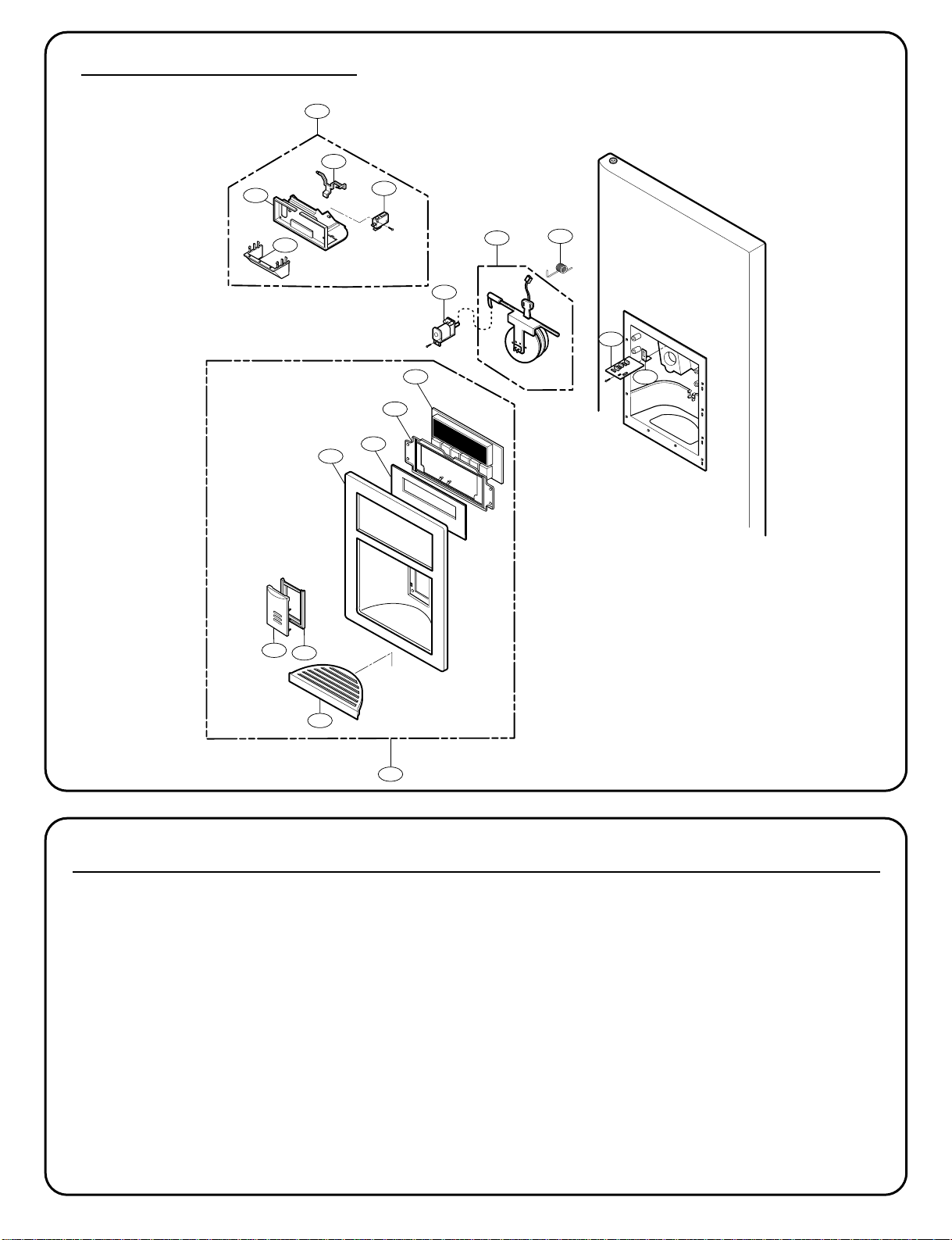
- 9 -
278D
278A
402C
405A
275A
276A
500B
278B
278C
276B
279A
279B
279D
279E
501A
280C
280B
281A
DISPENSER P
ARTS
LOCNo. 775*3(ST) 775*2(SW) 775*9(WB) 775*4(BI) Description
275A 5007JA3006R 5007JA3006R 5007JA3006R 5007JA3006R CapAssembly,Duct
276A 4970JA3025B 4970JA3025B 4970JA3025B 4970JA3025B Spring,Lever
276B 4930JA3043A 4930JA3043A 4930JA3043A 4930JA3043A Holder,Lever
278A 3017JA2008B 3017JA2008A 3017JA2008C 3017JA2008D Funnel Assembly
278B 3210JA1072B 3210JA1072A 3210JA1072C 3210JA1072D Frame,Funnel
278C 4510JA2027A 4510JA2027A 4510JA2027A 4510JA2027A Lever,Ice Maker
279A 3551JA1132M 3551JA1132L 3551JA1132N 3551JA1132P Cover Assembly,Dispenser
279B 3550JA1468B 3550JA1468A 3550JA1468C 3550JA1468D Cover,Dispenser
279C 3806JA1189A Decor, Cover Display
279D 3550JA2302A 3550JA2302A 3550JA2302A 3550JA2302A Cover,PCB
279E 4890JD1112A 4890JD1112A 4890JD1112A 4890JD1112A Decor,Glass Door
280B 4930JA2074B 4930JA2074B 4930JA2074B 4930JA2074B Holder,Button
280C 5020JA2040E 5020JA2040F 5020JA2040K 5020JA2040D Button,Lever
281A 3806JA2150A 3806JA2118A 3806JA2118C 3806JA2118D Decor,Drain
402C 6600JB3001E 6600JB3001E 6600JB3001E 6600JB3001E SWITCH,[MICRO]
405A 6421JB2002D 6421JB2002D 6421JB2002D 6421JB2002D SOLENOID ASSEMBLY
500B 6871JB2061B 6871JB2061B 6871JB2061B 6871JB2061B PCB Assembly,Sub
501A 6871JB1451A 6871JB1451A 6871JB1451A 6871JB1451A PCB Assembly,Display
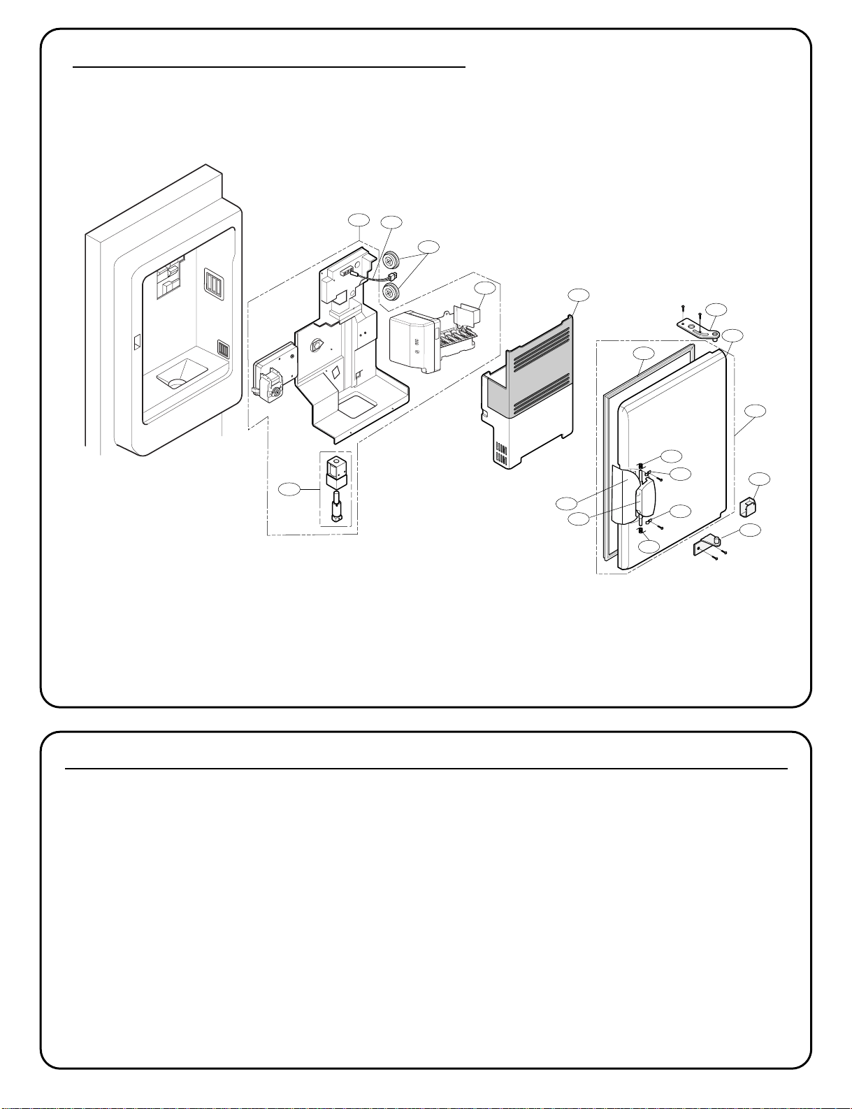
- 10 -
ICE MAKER & ICE BANK P
ARTS
LOCNo. 775** Description
600A 5989JB0001A Ice Maker Assembly, Kit
606A 4681JA1006D Motor, AC
610A 5075JA1044B Bucket Assembly, Ice
630A 3581JA1182B Door Assembly, Freeze Room
630B 5433JA2071B Door Foam Assembly, Home Bar
630C 4987JA2012A Gasket Assembly, Door
630D 3650HA2160A Handle, Home Bar
630E 3806JA2160A Decor, Handle
630F 4775JA2101A Hinge Assembly, Upper
630G 4775JA2102A Hinge Assembly, Lower
630H 3550JA3188A Cover, Home Bar
630J 4987JA3025B Gasket Assembly, Door
630K 4970JA3044A Spring
630L 4970JA3045A Spring
630M 4860JA3010A Clamp
630N 4860JA3010B Clamp
600A
630J
630C
630F
630B
630A
630H
630G
630K
630M
630N
630L
606A
600B
611A
630D
630E
614A