Loading ...
Loading ...
Loading ...
10 11
GAS CONNECTIONGAS CONNECTION
OPERATION ON N.G./S.N.G.GAS CONNECTION
This appliance is supplied for use with Natural Gas.
However, it can be converted for use with LPG.
Refer to LP conversion on pages 12 and 13.
Supply pipe sizing
The total hourly gas consumption for the appliance is
shown on the data label. The required supply pressure
(i.e. at inlet to appliance regulator) for each gas type
is shown on the data label, and given in Table 2.
Use this information in conjunction with the length of run,
number of elbows, tees and bends, the available service
pressure and the supply requirements of other installed
appliances to determine a suitable pipe size. For assistance
in this matter refer to the appropriate section of AS/NZS
5601.1 or AS/NZS 5601.2.
An AGA certified class B or D flexible connection may be
used to connect the cooktop in accordance with AS/NZS
5601.1, in particular section 5.9 and clause 6.10.1.8,
or AS/NZS 5601.2, in particular section 2.11. Where
a hose assembly is used and the cooktop is in the
installed position, the hose assembly shall be suitable for
connection to a fixed consumer piping outlet located at
a point 800 – 850mm
above the floor and in the region outside the width of
the appliance to a distance of 250mm. The point of
connection to consumer piping must be accessible
with appliance installed.
Elbow positioning
It is possible to reposition the elbow if required by
loosening the locking nut and elbow by using two spanners.
Re-tighten the entire assembly after the elbow has been
repositioned. When fitting elbow to appliance, ensure
that the sealing washer is fitted.
Checking the gas supply
1. Check the manometer zero point is correct.
2. Connect the manometer to the cooktop pressure point.
This is located on the regulator.
3. Turn on the gas supply and electricity and try to ignite
the gas.
TIPS & INFORMATION
NOTE! It will take additional time to light the gas for
the first time as air needs to be purged from the pipes.
4. With the appliance operating check the outlet pressure
• when all burners of the appliance are operating
at maximum,
• when the smallest burner of the appliance
is operating at minimum.
Under these conditions the outlet pressure should not
vary from the nominal outlet pressure of 1.00kPa by
more than +/– 0.20kPa.
Regulator
An appliance regulator is provided. The regulator must be
positioned so that the pressure test nipple is accessible
when the appliance is installed. Connect the gas supply
to the ½” B.S.P. internal thread inlet of the regulator. Refer
to ‘bench cutout’ (Figure 4) for connection point position.
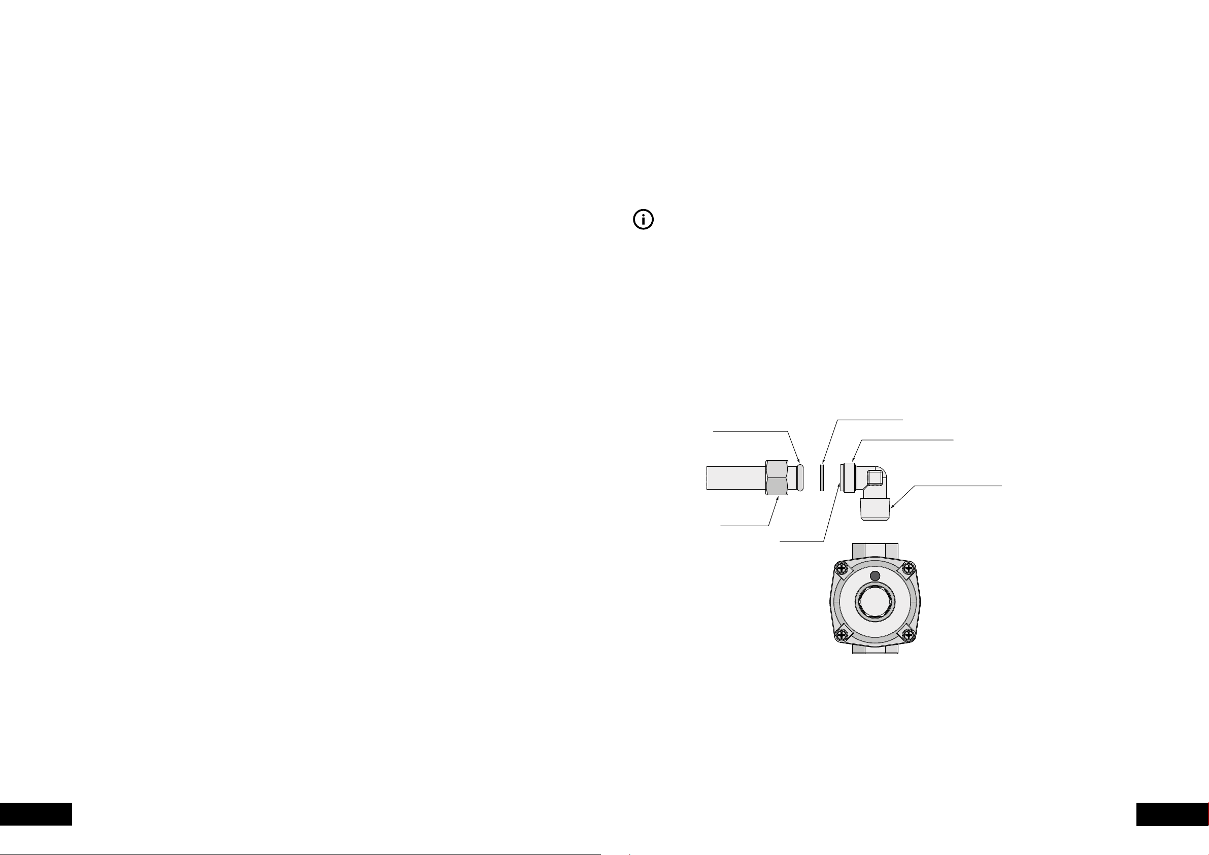
Assembly of Regulator
The assembly of the regulator to the cooktop manifold
is achieved via the elbow union and sealing washer
supplied, refer to figure 9 (page 11).
The ½” parallel thread connects to the manifold,
and the sealing washer is placed between the
manifold end and the flat face on the elbow.
The ½” tapered thread connects to the outlet of the
regulator, and is sealed on the thread using approved
thread sealing tape or approved thread sealing compound.
The inlet of the regulator is a ½” parallel thread and
is connected to consumer piping or hose assembly.
Regulators are supplied pre-adjusted and configured
by the component maker for use with Natural Gas.
The appliance installer is not required to make an
adjustment to obtain the correct outlet pressure setting.
An arrow on the base of the regulator indicates the
direction of gas flow when the inlet and outlet of the
regulator is orientated correctly. When the regulator
has been fitted check for leaks from the connections
with soapy water.
If the regulator appears to not be performing satisfactorily,
then check the following points.
1. If the outlet pressure is consistently too low then the
inlet pressure may be too low and adjustment of an
upstream regulator may be needed, or an upstream
regulator or valve with insufficient flow capacity may
be present in the gas supply line. If this is suspected
then it may be necessary to repeat the checks whilst
measuring both the inlet and outlet pressure to determine
if the inlet pressure is in the range 1.13 – 5kPa.
2. Check that the regulator has been fitted to the gas
supply line in the correct orientation, the arrow on the
base of the body indicates the direction of gas flow.
Once these checks have been completed, if the
regulator still fails to perform in a satisfactory manner
it should be replaced.
Figure 9
Manifold endform
Female nut
Flat face
Outlet
Regulator
Inlet
Sealing washer
½” Parallel thread
½” Tapered thread
Seal using approved
sealing tape or approved
thread sealing compound
Loading ...
Loading ...
Loading ...