Loading ...
Loading ...
Loading ...
8 9
INSTALLATION INSTALLATION
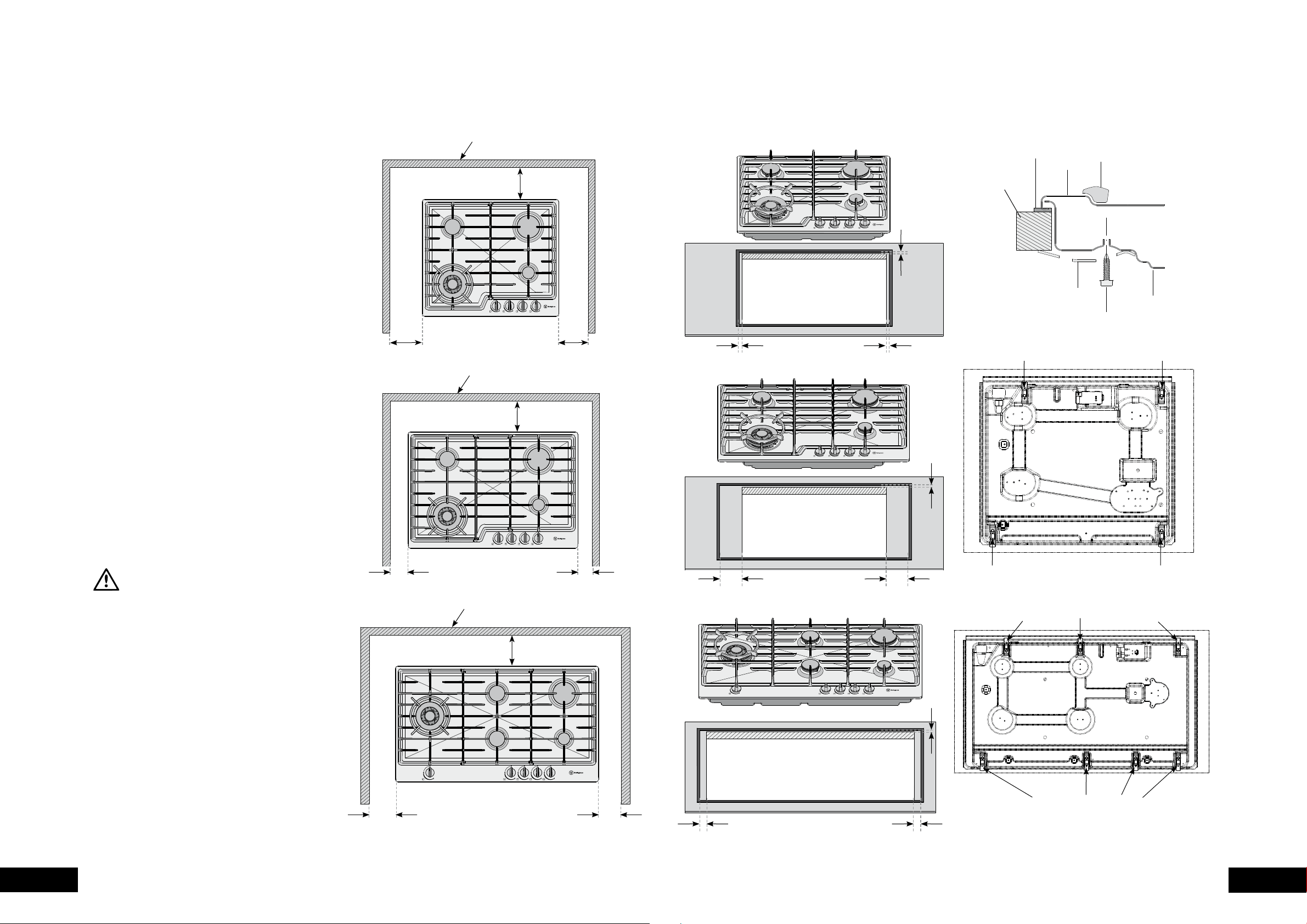
Figure 6–60cm models
Figure 6–75cm models
Figure 6–90cm models
Figure 7
Figure 8–60cm and 75cm models
Figure 8–90cm models
11mm
86mm 86mm
26mm 26mm
11mm
10mm
10mm
10mm
clamp location
clamp location Bottom view
clamp location
clamp location
possible clamp locations
possible clamp locations
Bottom view
trivet
hob
seal
benchtop
screw
clamp
burner box
1. The bench cutout should be made as per cutout
dimensions in Figure 4.
2. Adjacent walls, cupboards and protection for
combustible materials.
Ensure that the appliance is installed in accordance
with clauses 6.2.5 and 6.10.1.1 of AS/NZS
5601.1, or clauses 6.9.1 and 6.9.5 of AS/NZS
5601.2 with regard to clearances to combustible
surfaces and materials, and clearances to
rangehoods and exhaust fans.
To ensure clearances of 200mm from burners to
vertical combustible surfaces observe the minimum
dimensions shown in Figure 5.
Clearances to combustible surfaces may be reduced
if combustible surfaces are protected in accordance
with clause 6.10.1.2 of AS/NZS 5601.1, or clause
6.9.2 of AS/NZS 5601.2.
3. Optional Barrier
A barrier can be installed to prevent accidental contact
with the cooktop base, where the base of the cooktop
is accessible from below (i.e. inside a cupboard, etc).
An impression has been incorporated into the base to
ensure a minimum clearance of 15mm is maintained
between the base and the barrier. This barrier may
be made of any non-combustible, rigid material.
4. Fitting the cooktop into the bench
Carry out as follows:
• Place the seals supplied around the bench cut-out
as shown in Figure 6, taking care that the seals
meet without overlapping.
• Fit the pull-down clamps supplied to ensure
that the cooktop cannot move after installation.
WARNING
Failure to fix the cooktop to the bench could result
in loosening of the gas connection through movement
of the cooktop and a gas leak may result.
• Use the 4 clamps and screws supplied in the parts
bag for 4 burner models, and 6 clamps and screws
for 5 burner models.
• To assemble, attach the clamps to each corner
of the burner box via the screws provided.
• Fix the clamps as shown in Figure 7. The clamp
location points are shown in Figure 8.
• Remove excess seal.
• If the benchtop is less than the standard 33mm
thickness, use a packer between the bench and
the pull down clamps to ensure the cooktop is
properly secured.
combustible surface
combustible surface
combustible surface
119mm
79mm
99mm
131mm
91mm
111mm
131mm
131mm
Figure 5–60cm models
Figure 5–75cm models
Figure 5–90cm models
INSTALLATION PROCEDURE
131mm
Loading ...
Loading ...
Loading ...