Loading ...
Loading ...
Loading ...
ATTACHING THE CONTROL ROD
1. Makesurethe handleassemblyis in the highestposition.Referto
the OperationSection.
2. Removethehairpinclipsfromthe control rod,putthe rubber
washersin place.
3. Insertthe shorter,angledend of the controlrodthroughthe
indicatorbracketonthe shiftcoverandsecureit with the previ-
ouslyremovedhairpinclip.See Figure4.
Rubb_
Washers
Figure4
4. Insertthe longerend of the control rodthroughthe holeinthe
gearselectorhandleandsecurewitha cotterpin. SeeFigure5.
Gear Selector
Handle
Cotter Pin
Figure5
ATTACHING THE CLUTCH CABLE
1. Removethethreadedeyeboltand nut fromthe cableend.
2. Routethe clutchcableto the rightside of the handlemounting
bracketsandunderneaththe handle.
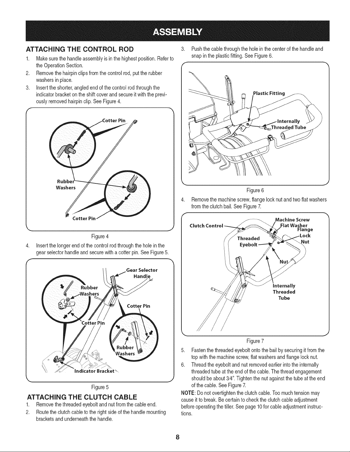
3. Pushthe cablethroughthe holein the centerof the handleand
snapin the plasticfitting. See Figure6.
Threaded Tube
Figure6
Removethe machinescrew,flangelocknut and two flat washers
fromthe clutchbail.See Figure7.
Machine Screw
Clutch Control Flat Washer
Range
Nut
internally
Threaded
Tu be
Figure7
5. Fastenthe threadedeyeboltontothe bail by securingit from the
top with the machinescrew,flatwashersand flangelocknut.
6. Threadtheeyeboltand nut removedearlierinto the internally
threadedtube atthe end of thecable.Thethreadengagement
shouldbeabout3/4".Tightenthe nutagainstthe tubeat the end
of the cable.SeeFigure7.
NOTE:Donot overtightentheclutchcable.Toomuchtensionmay
causeit to break.Becertainto checkthe clutchcableadjustment
beforeoperatingthe tiller.Seepage10for cableadjustmentinstruc-
tions.
8
Loading ...
Loading ...
Loading ...