Loading ...
Loading ...
Loading ...
4. Removethe idlerpulleyby removingthe boltand nut.
SeeFigure27.
5. Removethe old beltandinstallthe newbelt.Followthe instruc-
tionsin reverseorderto re-installthe belt keeperand belt cover.
SeeFigure27.
NOTE: Uponreassernbly,makecertainthe belt is routedoverthe idler
pulleyand insideof the beltkeepersbythe enginepulley.
TINES
Thetineswillwearwithuseandshouldbeinspectedat thebeginningof
eachtillingseasonandafterevery30operatinghours.Thetinescan be
replaced.Referto thePartsList sectionof this manualforpartnumbers.
Tine Inspection
Withuse,the tines will becomeshorter,narrowerand pointed.Badly
worntines will resultina lossof tillingdepth,and reducedeffective-
nesswhen choppingup andturningunderorganicmatter.
Removing/Installing a Tine Assembly
1. Removethe tine shieldend coversand sideshieldsby removing
thethree wingnuts on each sidethat securethem.
2. A fine assemblyconsistsof a left hand fineanda righthandfine.
NOTE:Thefine assemblymovesin a counter-rotatingmotionwith
the sharpedgesof thetinespositionedto enterthe soil firstwhen
counter-rotating.Notethis positionof thetines for reinstallationof the
newfine assemblies.
3. To removeafine assembly,simplyremovethe internalcotter pin
securingthe clevispin. SeeFigure29.
• ® Clevis Pin
/
_ J
Figure29
4. Removethe clevispin andslidethe assemblyto the outsideof
the unitandoff of the fine shaft.
5. Beforereinstallingthe fineassembly,inspectthe tine shaftfor
rust, roughspotsorburrs.Lightlyfile or sand,as needed.Applya
thincoat of greaseto the shaft.
6. Installeachfine assemblyso thatthe cutting(sharp)edgeof the
tineswillenterthesoilfirstwhenthetillermovesforward.Keepin
mindthatthesetinesarecounter-rotating,so securethetine as-
semblytothe tineshaftusingthe clevispinandinternalcotterpin.
ADJUSTMENTS
Handle
The handlemay be adjustedto thedesiredheight.Referto the
Assemblysectionfor details.
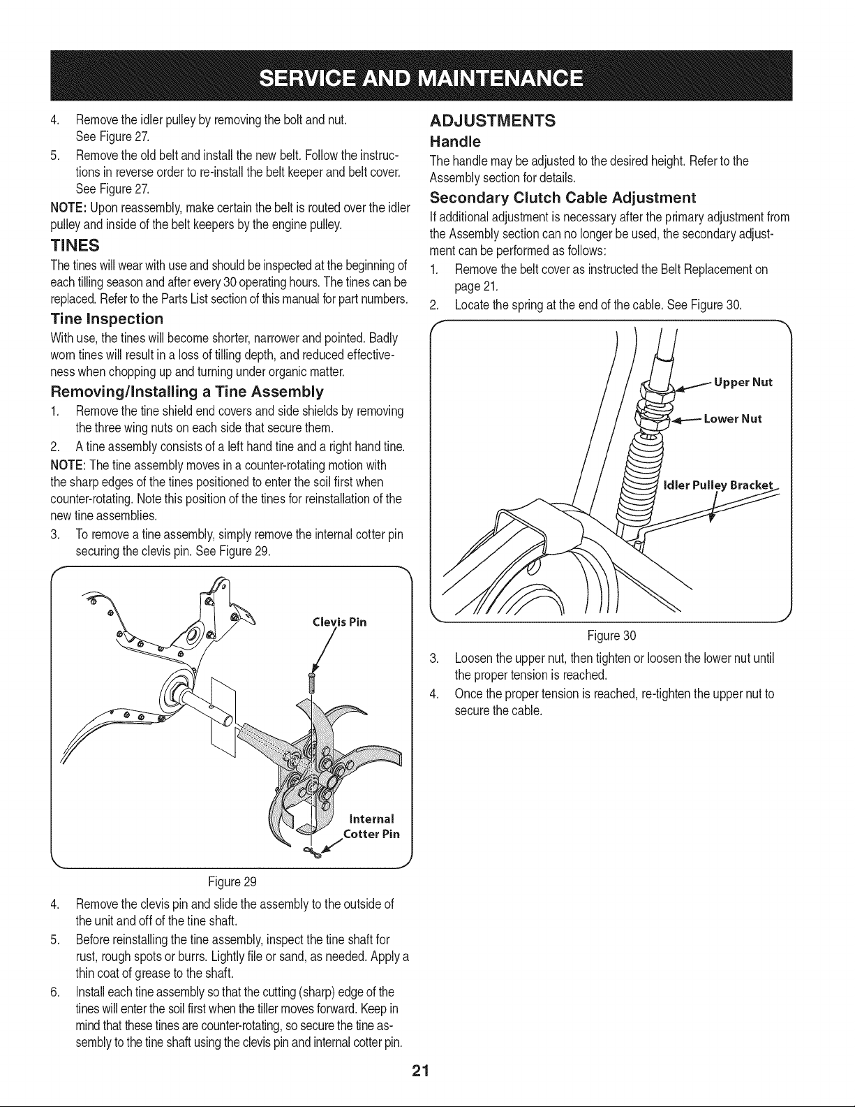
Secondary Clutch Cable Adjustment
Ifadditionaladjustmentis necessaryafterthe primaryadjustmentfrom
the Assemblysectioncan nolongerbe used,the secondaryadjust-
mentcan be performedas follows:
1. Removethe beltcoveras instructedthe Belt Replacementon
page21.
2. Locatethe springat the end of the cable.SeeFigure30.
.
4.
Figure30
Loosenthe uppernut, thentightenor loosenthe lowernut until
the propertensionis reached.
Once thepropertensionis reached,re-tightenthe uppernutto
securethe cable.
21
Loading ...
Loading ...
Loading ...