Loading ...
Loading ...
Loading ...
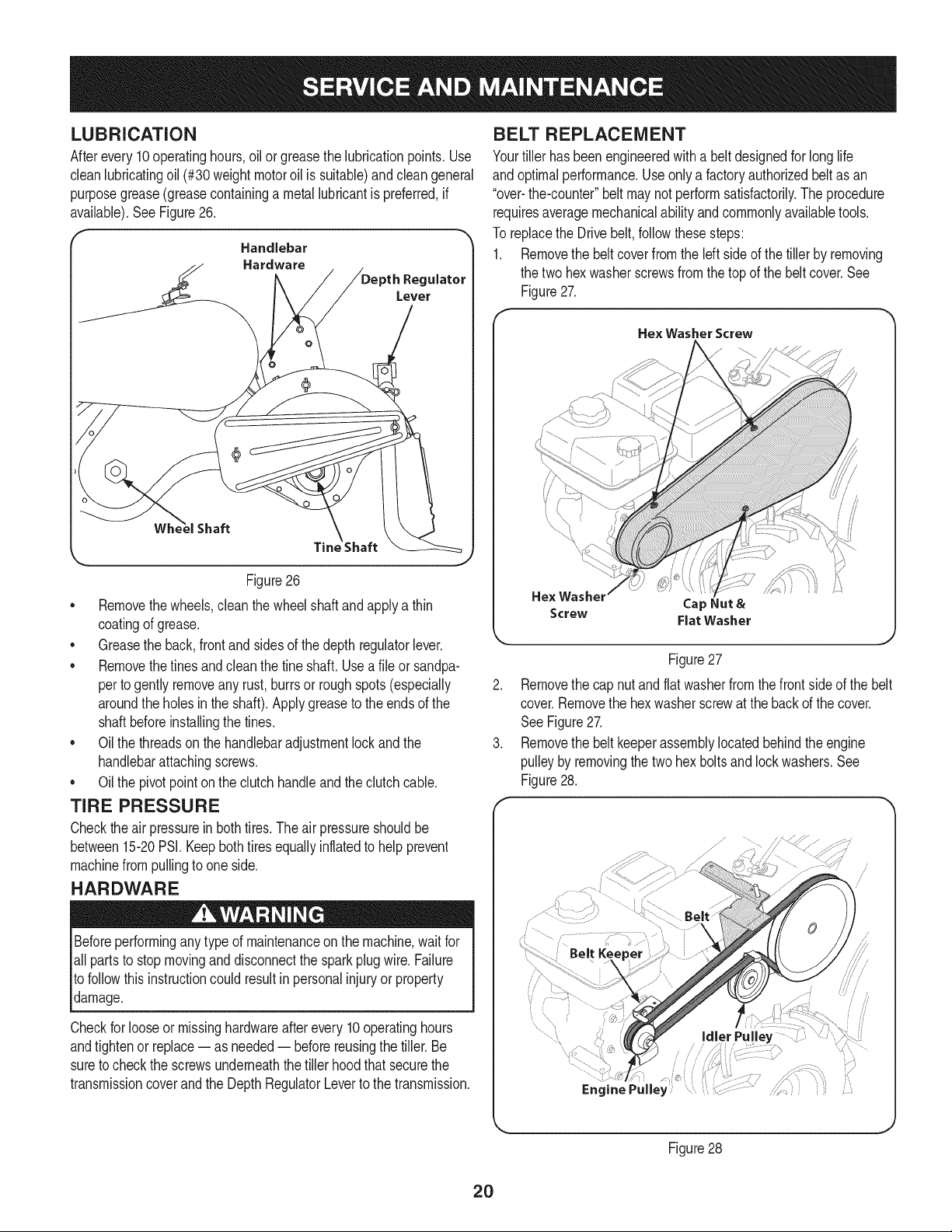
LUBRiCATiON
Afterevery10operatinghours,oilor greasethe lubricationpoints.Use
cleanlubricatingoil (#30weightmotoroil is suitable)and cleangeneral
purposegrease(greasecontaininga metallubricantis preferred,if
available).SeeFigure26.
_'_ Handlebar
Hardware
Regulator
Figure26
• Removethewheels,clean thewheelshaft andapplya thin
coatingof grease.
• Greasethe back,front and sidesof the depth regulatorlever.
• Removethetinesandcleanthe fine shaft. Usea file or sandpa-
perto gently removeany rust,burrsor roughspots(especially
aroundthe holesinthe shaft). Applygreaseto the endsof the
shaftbeforeinstallingthe tines.
• Oil the threadsonthe handlebaradjustmentlockand the
handlebarattachingscrews.
• Oil the pivotpointon the clutchhandleand the clutchcable.
TiRE PRESSURE
Checktheair pressurein bothtires.The airpressureshouldbe
between15-20PSI.Keepbothtiresequallyinflatedto helpprevent
machinefrompullingto one side.
HARDWARE
Beforeperformingany typeof maintenanceonthe machine,wait for
all partsto stopmovinganddisconnectthe spark plugwire. Failure
to followthis instructioncouldresult inpersonalinjuryor property
damage.
Checkfor looseor missinghardwareafterevery10operatinghours
andtightenor replace-- as needed-- beforereusingthe tiller.Be
sureto checkthe screwsunderneaththe tillerhood thatsecurethe
transmissioncoverand the DepthRegulatorLeverto thetransmission.
BELT REPLACEMENT
Yourtiller hasbeenengineeredwith a beltdesignedfor long life
andoptimalperformance.Useonly a factoryauthorizedbeltas an
"over-the-counter"belt maynot performsatisfactorily.The procedure
requiresaveragemechanicalabilityandcommonlyavailabletools.
To replacethe Drivebelt,followthesesteps:
1. Removethe beltcoverfromthe left sideof the tiller by removing
the two hexwasherscrewsfromthe topof the beltcover.See
Figure27.
Hex Washer Screw
He× Washel
Cap Nut &
Screw Flat Washer
Figure27
Removethe cap nutandflatwasherfromthe front sideof the belt
cover.Removethe hexwasherscrewat the backof the cover.
SeeFigure27.
Removethe belt keeperassemblylocatedbehindthe engine
pulleyby removingthe two hex boltsand lockwashers.See
Figure28.
...............................
/ 7\
...........!..... Idler Pulley
Figure28
2O
Loading ...
Loading ...
Loading ...