Loading ...
Loading ...
Loading ...
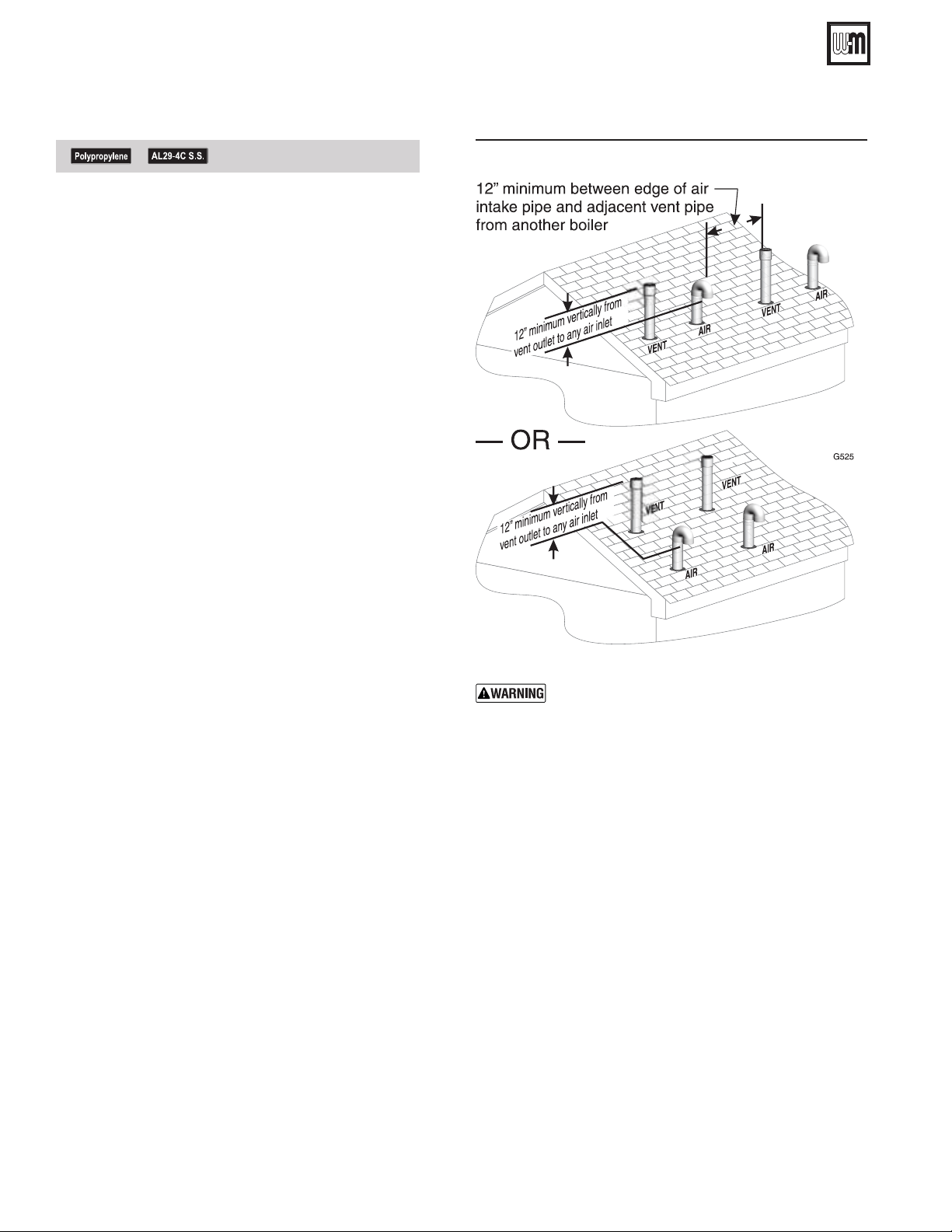
Figure 31
Also maintain maximum distances between the
vent and air pipes for each boiler as shown in
Figure 30, page 25.
See notices on previous page.
Part number 550-100-325/0419
26
AquaBalance
®
Series 2 Wall Mount Gas-fired Water Boiler – Boiler Manual
1. Air pipe penetration:
a. Cut a hole for the air pipe. Size the air pipe hole as
close as desired to the air pipe outside diameter.
2. Vent pipe penetration:
a. Cut a hole for the vent pipe. For either combustible
or noncombustible construction, size the vent pipe
hole at least 0.4” larger than the vent pipe diameter.
b. Insert a galvanized metal thimble in the vent pipe
hole.
3. Space the air and vent holes
no closer than the minimum
spacings shown in Figure 31.
4. Follow all local codes and vent pipe manufacturer’s
instructions for isolation of vent pipe when passing
through floors, ceilings and roofs.
5. For Canadian installations, provide clearances required
by CSA B149.1 or B149.2 Installation Code and a
ULC S636 compliant vent kit.
6. Provide flashing and sealing boots sized for the vent
pipe and air pipe. Follow all vent pipe manufacturer’s
instructions.
Termination and fittings
1. Prepare the vent termination elbow and the air termina-
tion elbow (Figure 30, page 25) by inserting bird screens.
Bird screens must be purchased separately. See the parts
list at the end of this manual for part numbers.
2. The air piping must terminate in a down-turned 180-de-
gree return bend as shown in Figure 30, page 25. Locate
the air inlet pipe no further than 12 inches from the
center of the vent pipe. This placement avoids recircu-
lation of flue products into the combustion air stream.
3. The vent piping must terminate in an up-turned cou-
pling as shown in Figure 30, page 25. The top of the
coupling must be at least 12 inches above the air intake.
The air inlet pipe and vent pipe can be located in any
desired position on the roof, but must always be no fur-
ther than 12 inches apart (center to center) and with the
vent termination at least 12 inches above the air intake.
4. Maintain the required dimensions of the finished termi-
nation piping as shown in Figure 30, page 25.
5. Do not extend exposed vent pipe outside of building
more than shown in this document. Condensate could
freeze and block vent pipe.
12 DIRECT VENT —
(continued)
Loading ...
Loading ...
Loading ...