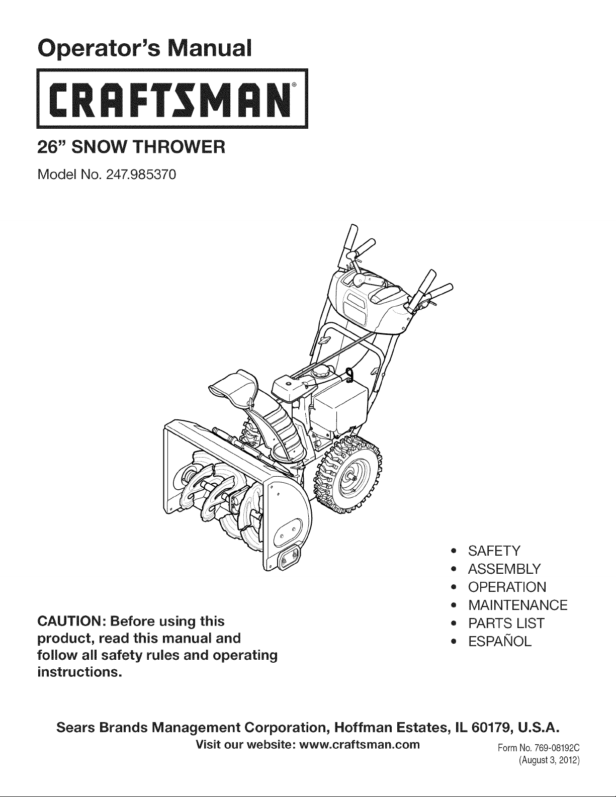
Operator's Manual
CRRFr MRN
26" SNOW THROWER
Model No. 247.985370
CAUTION" Before using this
product, read this manual and
follow all safety rules and operating
instructions.
,, SAFETY
o ASSEMBLY
OPERATION
MAINTENANCE
PARTS LIST
o ESPANOL
Sears Brands Management Corporation, Hoffman Estates, IL 60179, U.S.A.
Visit our website: www.craftsman.com FormNo. 769-08192C
(August3, 2012)
WarrantyStatement.................... Page2
SafeOperationPractices.............. Pages3-6
Assembly......................... Pages8-13
Operation........................ Pages14-17
Service&Maintenance.............. Pages18-23
Off-SeasonStorage................... Page24
Troubleshooting...................... Page25
PartsList......................... Pages26-43
RepairProtectionAgreement............ Page47
Espadol............................. Page48
ServiceNumbers................... BackPage
CRAFTSMANTWOYEARFULL WARRANTY
FORTWOYEARSfromthedateofpurchase,thisproductiswarrantedagainstanydefectsinmaterialorworkmanship.Defectiveproductwill
receivefreerepairorfreereplacementifrepairisunavailable.
Forwarrantycoverage details to obtain repairor replacement,visit the website: www.craftsman.com
This warranty covers ONLYdefects in material andworkmanship. Warranty coverage does NOTinclude:
• Expendableitemsthatcan wearoutfromnormalusewithinthewarrantyperiod,includingbut not limitedto augers,augerpaddles,drift
cutters,skidshoes,shaveplate,shearpins, spark plug,air cleaner,belts,and oil filter.
• Standardmaintenanceservicing,oilchanges,or tune-ups.
• Tire replacementor repaircausedby puncturesfrom outsideobjects,suchas nails,thorns,stumps,or glass.
• Tireor wheelreplacementor repairresultingfromnormalwear,accident,or improperoperationor maintenance.
• Repairsnecessarybecauseof operatorabuse, includingbutnot limitedto damagecausedby over-speedingthe engine,or fromimpacting
objectsthat bendthe frame,auger shaft,etc.
• Repairsnecessarybecauseof operatornegligence,includingbut not limitedto,electricalandmechanicaldamagecausedby improper
storage,failureto usethe propergradeandamountof engineoil, or failureto maintainthe equipmentaccordingto the instructionscontained
inthe operator'smanual.
• Engine(fuelsystem)cleaningor repairscausedbyfuel determinedto be contaminatedoroxidized(stale).In general,fuel shouldbe used
within30 daysof its purchasedate.
Normaldeteriorationandwearof the exteriorfinishes,or productlabelreplacement.
Thiswarrantyis void if this productis ever usedwhileprovidingcommercialservicesor if rentedto anotherperson.
Thiswarrantygivesyou specificlegalrights,and you mayalso haveotherrightswhich vary from stateto state.
Sears Brands Management Corporation, Hoffman Estates, IL 60179
EngineOilType: SAE5W-30
EngineOilCapacity: 20ounces
FuelCapacity: 2 Quarts
SparkPlug: F6RTC(951-10292)
SparkPlugGap: .020"to .030"
Model Number.................................................................
Serial Number .................................................................
Dateof Purchase .............................................................
Recordthe modelnumber,serialnumber
anddateof purchaseabove
© Sears Brands,LLC
2
Thissymbolpointsout importantsafetyinstructionswhich,if not
followed,couldendangerthepersonalsafetyand/orpropertyof
yourselfand others. Readandfollowall instructionsin thismanual
beforeattemptingto operatethismachine.Failureto complywith
theseinstructionsmayresultin personalinjury.Whenyou seethis
symbol,HEEDITSWARNING!
CALIFORNIA PROPOSITION 65
EngineExhaust,someof itsconstituents,andcertainvehicle
componentscontainoremit chemicalsknownto Stateof California
to causecancerand birthdefects or otherreproductiveharm,
Thismachinewasbuiltto be operatedaccordingto the safeopera-
tion practicesinthis manual.As withanytypeof powerequipment,
carelessnessor error on the partof the operatorcan resultin serious
injury.Thismachineis capableof amputatingfingers,hands,toes
andfeet and throwingdebris.Failureto observethe followingsafety
instructionscouldresultin seriousinjuryor death.
Your Responsibility--Restrict the use of this powermachineto
personswho read,understandandfollow thewarningsand instruc-
tionsin this manualand on the machine,
SAVE THESE INSTRUCTIONS!
TRAiNiNG
• Read,understand,and followall instructionson the machineand
in themanual(s)beforeattemptingto assembleandoperate.
Failureto do socan resultinseriousinjuryto the operatorand/
orbystanders.Keepthismanualin a safe placeforfuture and
regularreferenceandfor orderingreplacementparts.
• Befamiliarwithall controlsand their properoperation.Knowhow
to stopthe machineanddisengagethemquickly.
• Neverallowchildrenunder 14 yearsof ageto operatethis
machine.Children14andover shouldreadand understandthe
instructionsand safe operationpracticesin thismanualand on
the machineandbe trainedand supervisedby anadult.
Neverallowadultsto operatethis machinewithoutproper
instruction.
• Thrownobjectscan causeseriouspersonalinjury. Planyour
snow-throwingpatternto avoiddischargeof materialtoward
roads,bystandersandthe like.
Keepbystanders,pets andchildrenat least75 feet from the
machinewhile it is in operation.Stopmachineif anyoneenters
the area.
• Exercisecautionto avoidslippingor falling,especiallywhen
operatingin reverse.
PREPARATION
Thoroughlyinspectthearea wherethe equipmentisto be used.
Removeall doormats,newspapers,sleds,boards,wiresandother
foreignobjects,whichcouldbe trippedoveror thrownby the auger/
impeller.
• Alwayswear safetyglassesor eyeshieldsduringoperationand
while performingan adjustmentor repairto protectyoureyes.
Thrownobjectswhichricochetcancause seriousinjuryto the
eyes.
Donot operatewithoutwearingadequatewinteroutergarments.
Donot wearjewelry,long scarvesor otherlooseclothing,which
could becomeentangledin movingparts.Wearfootwearwhich
will improvefootingonslipperysurfaces.
Usea groundedthree-wireextensioncordand receptaclefor all
machineswith electricstartengines.
Disengageall controlleversbeforestartingthe engine.
Adjustcollectorhousingheightto cleargravelorcrushedrock
surfaces.
• Neverattemptto make anyadjustmentswhileengineis running,
exceptwherespecificallyrecommendedinthe operator'smanual.
Letengineandmachineadjustto outdoortemperaturebefore
startingto clearsnow.
3
Safe Handling of Gasoline
Toavoidpersonalinjuryor propertydamageuseextremecare in
handlinggasoline.Gasolineis extremelyflammableandthe vaporsare
explosive.Seriouspersonalinjurycan occurwhengasolineis spilled
onyourselfor yourclotheswhichcan ignite. Washyour skin and
changeclothesimmediately.
• Useonlyan approvedgasolinecontainer.
• Extinguishall cigarettes,cigars,pipesandother sourcesof
ignition.
• Neverfuel machineindoors.
• Neverremovegas capor add fuel whilethe engineis hot or
running.
• Allowengineto coolat leasttwo minutesbeforerefueling.
• Neveroverfill fueltank. Fill tankto nomorethan1/2inchbelow
bottomof filler neck to providespaceforfuel expansion.
• Replacegasolinecapandtightensecurely.
• Ifgasolineis spilled,wipe it off theengineandequipment.Move
machineto anotherarea.Wait5 minutesbeforestartingthe
engine.
• Neverstorethe machineorfuel containerinsidewherethereis an
openflame,sparkor pilotlight(e.g. furnace,waterheater,space
heater,clothesdryeretc.).
• Allowmachineto cool at least5 minutesbeforestoring.
• Neverfill containersinsidea vehicleor ona truckor trailerbed
witha plasticliner.Alwaysplacecontainersonthe groundaway
fromyour vehiclebeforefilling.
• If possible,removegas-poweredequipmentfromthe truckor
trailerandrefuelit onthe ground.If this is not possible,then refuel
suchequipmenton a trailerwitha portablecontainer,ratherthan
froma gasolinedispensernozzle.
• Keepthe nozzlein contactwiththe rimof the fuel tankor
containeropeningat alltimes untilfuelingis complete.Do not use
a nozzlelock-opendevice.
OPERATION
• Do not puthandsorfeetnear rotatingparts,in the auger/impeller
housingor chuteassembly.Contactwith the rotatingpartscan
amputatehandsandfeet.
• Theauger/impellercontrolleveris a safetydevice.Neverbypass
itsoperation.Doingso makesthe machineunsafeandmaycause
personalinjury.
• Thecontrolleversmustoperateeasilyin bothdirectionsand
automaticallyreturnto the disengagedpositionwhenreleased.
• Neveroperatewith a missingor damagedchuteassembly.Keep
all safetydevicesin placeand working.
• Neverrunanengine indoorsor in a poorlyventilatedarea. Engine
exhaustcontainscarbonmonoxide,an odorlessanddeadlygas.
• Do notoperatemachinewhileunderthe influenceof alcoholor
drugs.
• Mufflerand enginebecomehotandcan causea burn.Do not
touch.Keepchildrenaway.
• Exerciseextremecautionwhenoperatingon or crossinggravel
surfaces.Stay alertfor hidden hazardsor traffic.
Exercisecautionwhenchangingdirectionandwhileoperatingon
slopes.Do notoperateon steepslopes.
Planyoursnow-throwingpatternto avoiddischargetowards
windows,walls,carsetc. Thus,avoidingpossibleproperty
damageor personalinjurycausedby a ricochet.
Neverdirectdischargeat children,bystandersand petsor allow
anyoneinfrontof the machine.
Donot overloadmachinecapacityby attemptingto clearsnowat
too fastof a rate.
Neveroperatethis machinewithoutgoodvisibilityorlight. Always
be sureof yourfootingand keepa firmholdon the handles.Walk,
neverrun.
Disengagepowerto theauger/impellerwhentransportingor not
in use.
Neveroperatemachineat hightransportspeedson slippery
surfaces.Lookdownand behindand usecare whenbackingup.
Ifthe machineshouldstart to vibrateabnormally,stopthe engine,
disconnectthe sparkplugwire and groundit againstthe engine.
Inspectthoroughlyfor damage.Repairanydamagebefore
startingandoperating.
Disengageall controlleversand stopenginebeforeyouleave
the operatingposition(behindthe handles).Waituntilthe auger/
impellercomesto a completestop beforeuncloggingthechute
assembly,makingany adjustments,or inspections.
Neverput yourhandinthe dischargeor collectoropenings.Do
not unclogchuteassemblywhileengineis running.Shutoff
engineand remainbehindhandlesuntilall movingpartshave
stoppedbeforeunclogging.
Useonly attachmentsandaccessoriesapprovedby the manufac-
turer (e.g.wheelweights,tire chains,cabsetc.). Forinformation
concerningtheseitems,call 1-800-469-4663.
Whenstartingengine,pull cord slowlyuntilresistanceis felt, then
pull rapidly.Rapidretractionof startercord(kickback)will pull
handand armtowardenginefasterthan youcan let go. Broken
bones,fractures,bruisesor sprainscould result.
Ifsituationsoccurwhichare notcoveredinthis manual,use care
andgood judgment.
Toorderpartsor scheduleservicefor thisproduct,call 1-800-
469-4663.
CLEARING A CLOGGED DISCHARGE CHUTE
Handcontactwith the rotatingimpellerinsidethe dischargechute
is the mostcommoncauseof injuryassociatedwith snowthrowers.
Neveruse yourhandto cleanout thedischargechute.
Toclear thechute:
1. SHUTTHEENGINEOFF!
2. Wait 10secondsto be surethe impellerbladeshavestopped
rotating.
3. Alwaysusea clean-outtool,not yourhands.
4
MAINTENANCE & STORAGE
• Nevertamperwithsafetydevices.Checktheirproperoperation
regularly.Referto the maintenanceand adjustmentsectionsof
thismanual.
• Beforecleaning,repairing,or inspectingmachinedisengageall
controlleversandstop the engine.Waituntilthe auger/impeller
cometo a completestop.Disconnectthe sparkplug wireand
groundagainsttheengineto preventunintendedstarting.
Checkboltsand screwsfor propertightnessat frequentintervals
to keepthe machineinsafeworkingcondition.Also,visually
inspectmachinefor anydamage.
Do notchangetheenginegovernorsettingor over-speedthe
engine.Thegovernorcontrolsthe maximumsafeoperatingspeed
of the engine.
Snowthrowershaveplatesand skid shoesaresubjectto wear
anddamage.Foryoursafetyprotection,frequentlycheckall
componentsand replacewithoriginalequipmentmanufacturer's
(OEM)partsonlyas listedinthe Partspagesof thisoperator's
manual.Useof partswhich do not meetthe originalequipment
specificationsmayleadto improperperformanceandcompro-
misesafety!
Checkcontrolleversperiodicallyto verifytheyengageanddisen-
gageproperlyandadjust,if necessary.Referto the adjustment
sectioninthisoperator'smanualfor instructions.
Maintainor replacesafetyand instructionlabels,as necessary.
Observeproperdisposallawsand regulationsfor gas,oil,etc. to
protectthe environment.
Priorto storing,run machinea few minutestoclear snowfrom
machineand preventfreezeup of auger/impeller.
Neverstorethe machineorfuel containerinsidewherethereisan
openflame,sparkorpilot lightsuchas a waterheater,furnace,
clothesdryer etc.
Alwaysreferto the operator'smanualfor properinstructionson
off-seasonstorage.
Checkfuelline,tank, cap,andfittingsfrequentlyfor cracksor
leaks.Replaceif necessary.
Do notcrankenginewithspark plug removed.
Accordingto the ConsumerProductsSafetyCommission(CPSC)
andthe U.S.EnvironmentalProtectionAgency(EPA),this product
hasan AverageUsefulLifeof seven(7) years,or 60 hoursof
operation.At the endof theAverageUsefulLifehavethe machine
inspectedannuallybyan authorizedservicedealerto ensurethat
allmechanicaland safetysystemsareworkingproperlyand not
wornexcessively.Failureto do so can resultin accidents,injuries
ordeath.
DO NOT MODIFY ENGINE
Toavoidseriousinjuryor death,do not modifyengine in any way.
Tamperingwiththe governorsettingcanlead to a runawayengineand
causeit to operateat unsafespeeds.Nevertamperwithfactorysetting
of enginegovernor.
NOTICE REGARDING EMiSSiONS
Engineswhich are certifiedtocomplywith Californiaand federal
EPAemissionregulationsfor SORE(SmallOff RoadEquipment)are
certifiedto operateon regularunleadedgasoline,and mayinclude
the followingemissioncontrol systems:EngineModification(EM),
OxidizingCatalyst(OC), SecondaryAir Injection(SAI)and ThreeWay
Catalyst(TWO)if so equipped.
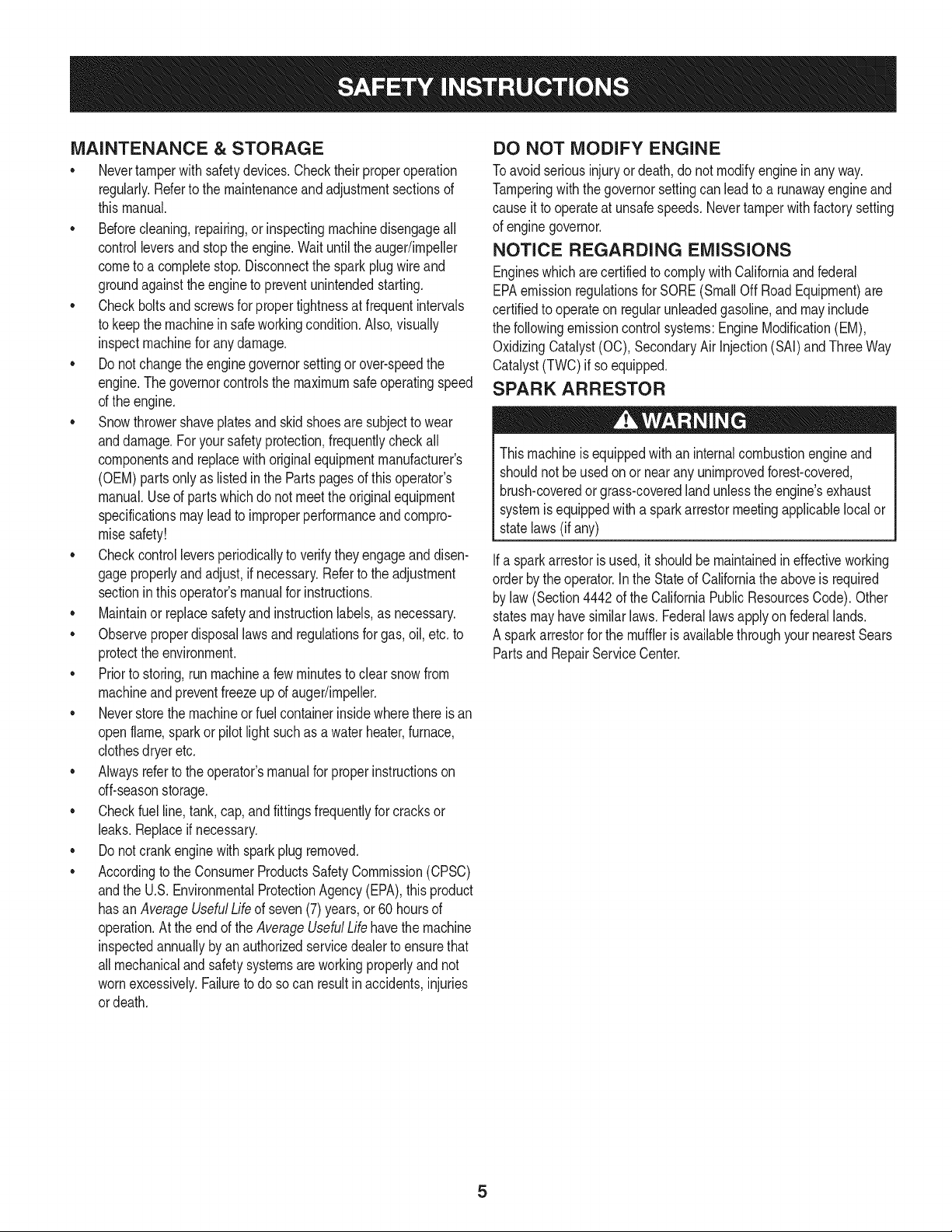
SPARK ARRESTOR
Thismachineisequippedwithan internalcombustionengineand
shouldnotbe usedon or nearany unimprovedforest-covered,
brush-coveredor grass-coveredland unlessthe engine'sexhaust
systemisequippedwith a sparkarrestormeetingapplicablelocalor
statelaws(if any)
Ifa sparkarrestoris used,it shouldbe maintainedin effectiveworking
orderby theoperator.Inthe Stateof Californiathe aboveis required
bylaw (Section4442of the CaliforniaPublicResourcesCode).Other
statesmayhavesimilarlaws. Federallawsapplyon federallands.
A spark arrestorfor the muffleris availablethroughyournearestSears
PartsandRepairServiceCenter.
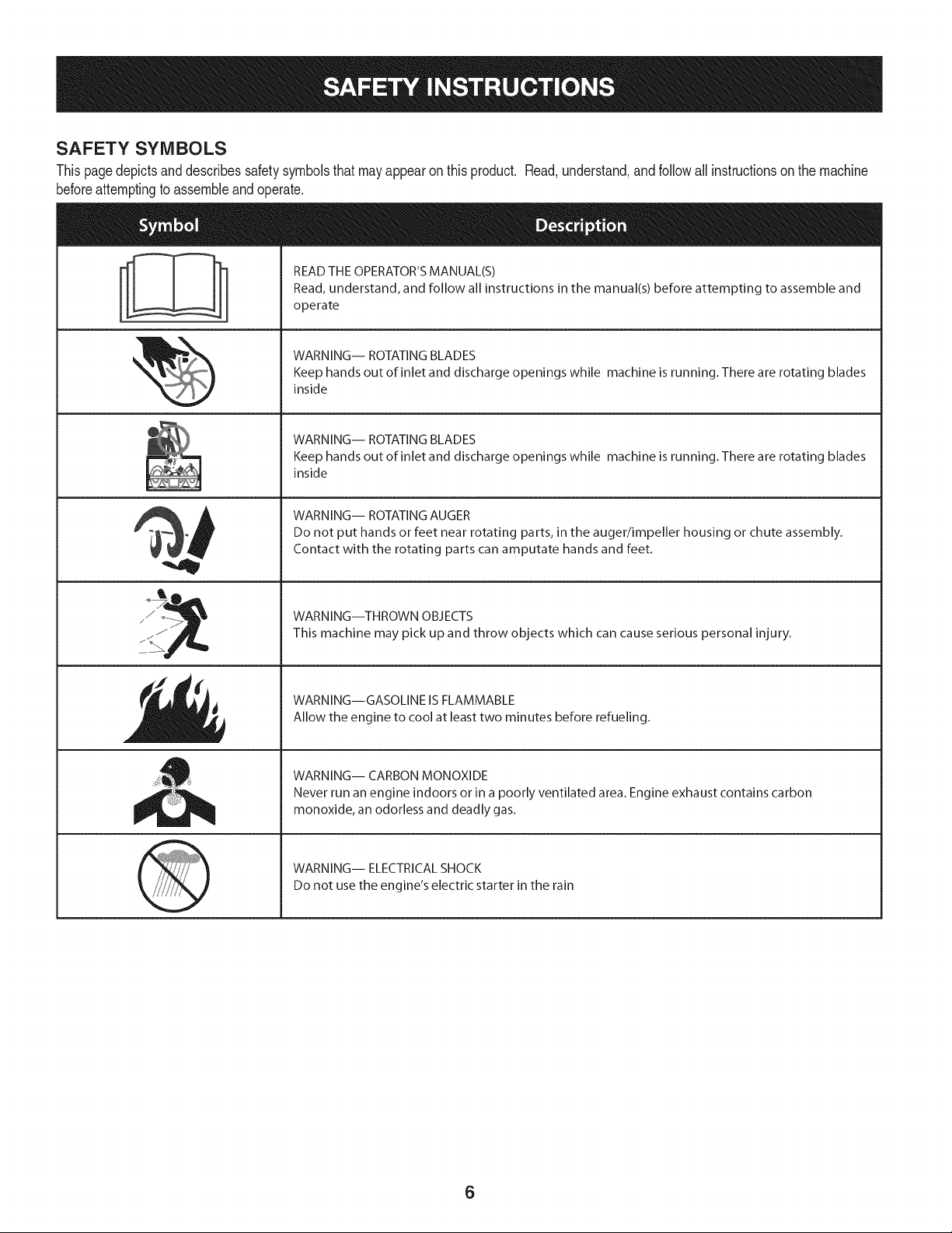
SAFETY SYMBOLS
Thispagedepictsanddescribessafetysymbolsthatmayappearon this product. Read,understand,andfollowall instructionson the machine
beforeattemptingto assembleandoperate.
. +
i
i
"JIp
READ THE OPERATOR'S MANUAL(S)
Read, understand, and follow all instructions in the manual(s) before attempting to assemble and
operate
WARNING-- ROTATING BLADES
Keep hands out of inlet and discharge openings while machine is running. There are rotating blades
inside
WARNING-- ROTATING BLADES
Keep hands out of inlet and discharge openings while machine is running. There are rotating blades
inside
WARNING-- ROTATING AUGER
Do not put hands or feet near rotating parts, in the auger/impeller housing or chute assembly.
Contact with the rotating parts can amputate hands and feet.
WARNING--THROWN OBJECTS
This machine may pick up and throw objects which can cause serious personal injury.
WARNING--GASOLINE IS FLAMMABLE
Allow the engine to cool at least two minutes before refueling.
WARNING-- CARBON MONOXIDE
Never run an engine indoors or in a poorly ventilated area. Engine exhaust contains carbon
monoxide, an odorless and deadly gas+
WARNING-- ELECTRICAL SHOCK
Do not use the engine's electric starter in the rain
6

Thispageleftintentionallyblank.
7
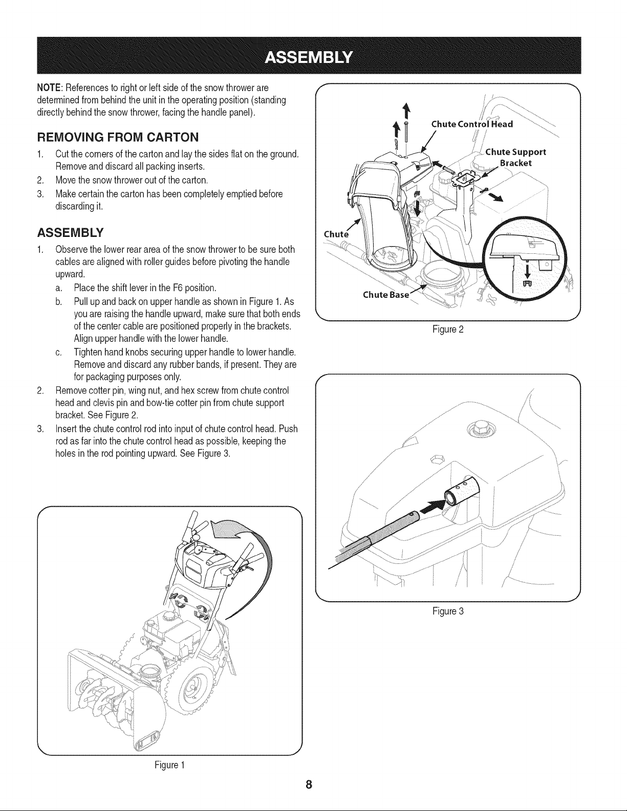
NOTE:Referencesto rightorleft sideof the snowthrowerare
determinedfrombehindthe unit inthe operatingposition(standing
directlybehindthe snowthrower,facingthe handlepanel).
REMOVING FROM CARTON
1. Cutthe cornersof thecartonandlay the sidesflaton the ground.
Removeand discard allpackinginserts.
2. Movethe snowthrowerout of thecarton.
3. Makecertainthe cartonhas beencompletelyemptiedbefore
discardingit.
ASSEMBLY
1. Observethe lowerreararea of the snowthrowerto be sure both
cablesarealignedwith rollerguidesbeforepivotingthe handle
upward.
a. Placethe shiftleverin the F6position.
b. Pullupandbackon upperhandleas shownin Figure1.As
youare raisingthe handleupward,makesurethat bothends
of the centercablearepositionedproperlyinthe brackets.
Alignupperhandlewiththe lowerhandle.
c. Tightenhandknobssecuringupper handleto lowerhandle.
Removeand discard any rubberbands,if present.Theyare
for packagingpurposesonly.
2. Removecotter pin,wingnut,and hexscrewfromchute control
headandclevis pin and bow-tiecotterpin from chutesupport
bracket.See Figure2.
3. Insertthe chutecontrolrodintoinputof chutecontrolhead.Push
rodas far intothe chutecontrolheadas possible,keepingthe
holesinthe rodpointingupward.See Figure3.
Chute Control Head
_ort
Bracket
Figure2
f
/
\
Figure3
_J
Figure1
8
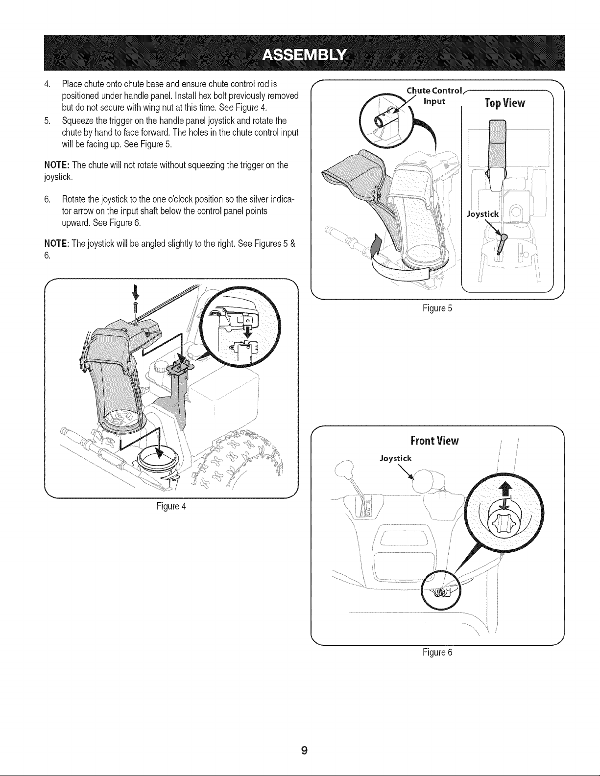
4. Placechuteontochutebaseandensurechute control rodis
positionedunderhandlepanel.Installhex boltpreviouslyremoved
but donot securewith wingnut at this time.See Figure4.
5. Squeezethe triggeron thehandle paneljoystickand rotatethe
chuteby handto face forward.Theholes inthe chutecontrolinput
will befacingup.See Figure5.
NOTE:The chutewill not rotatewithoutsqueezingthe triggeronthe
joystick.
6. Rotatethejoystickto the oneo'clockpositionsothe silverindica-
tor arrowon the inputshaftbelowthe controlpanelpoints
upward.SeeFigure6.
NOTE:Thejoystickwillbe angledslightlyto the right.SeeFigures5 &
6.
Figure4
f
Chute Controlf
Figure5
f
FroatView
Joystick
Figure6
J
9
. Makesureall cables are routedto the left of the chutecontrol
rod.Lineupthe hole in the rodwiththearrowon the inputshaft
and insertthe end of the rodinto the inputshaftbelowjoystickon
handlepanel.SeeFigure7.
NOTE:Thechutecontrolrodwill fit snugglyintothe inputshaft.
Supportthe rear of thedash panelwithone handwhileinsertingthe
rodwithyourotherhandto ensurethe rodis insertedell the way into
the input shaft.
8. Nowpushthe chutecontrolrodbacktowardsthe handlepanel
untilthe holeinthe rodlines up with the hole in the chutecontrol
inputclosestto the chutecontrolhead. Insertthe cotterpin. See
Figure8.
NOTE:The secondholeis usedto achievefurtherengagementof the
rodintothe inputshaft if requiredandcan be usedlaterfor adjustment
if the chutedoes notfullyrotate.Referto the Service& Maintenance
sectionfor ChuteControlRodadjustments.
9. Finishsecuringchute controlheadto chutesupportbracketwith
wing nut,andclevispin and bow-tiecotterpin removedearlier.Do
notovertighten.SeeFigure9.
/i _
.J
Figure8
/
/
' .....................................................i_"i
}
Figure7
Figure9
10
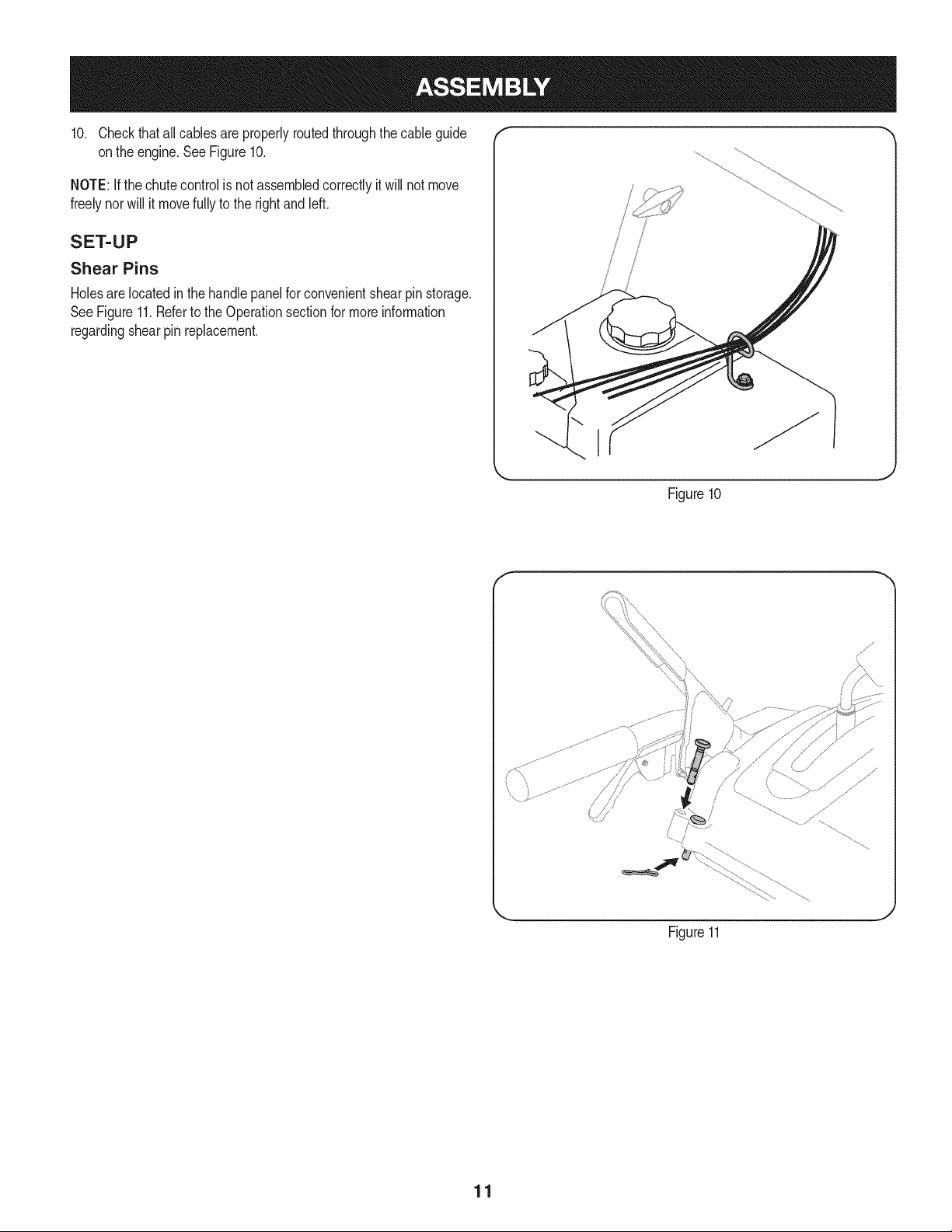
10. Checkthatall cablesare properlyroutedthroughthecable guide
onthe engine.SeeFigure10.
NOTE:Ifthe chutecontrolis not assembledcorrectlyit will not move
freelynorwill it movefullyto the rightand left.
SET-UP
Shear Pins
Holesare locatedin the handlepanelfor convenientshearpin storage.
SeeFigure11.Referto the Operationsectionfor moreinformation
regardingshearpin replacement.
/
i
/
!
I
Figure10
f
Figure11
J
11
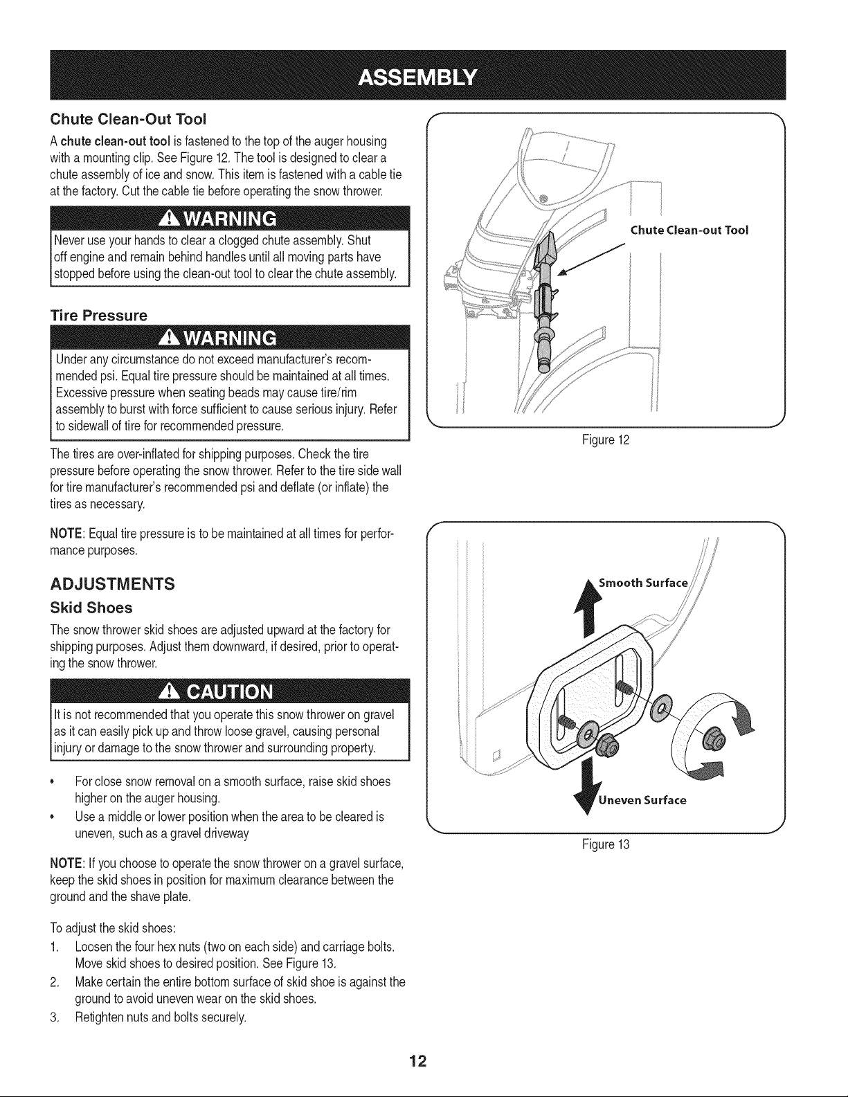
Chute Clean=Out Tool
Achute clean-out tool is fastenedto the top of the augerhousing
witha mountingclip. SeeFigure12.The tool is designedto cleara
chuteassemblyof ice andsnow.Thisitemis fastenedwith a cabletie
at the factory.Cut thecable tie beforeoperatingthe snowthrower.
loft _1 .allmovingloartshave
stoppedbeforeusingthe clean-outtool to clearthe chuteassembly.
Tire Pressure
Underanycircumstancedo notexceed manufacturer'srecom-
mendedpsi. Equaltire pressureshouldbe maintainedat all times.
Excessivepressurewhenseatingbeadsmaycausetire/rim
assemblyto burstwithforce sufficientto causeseriousinjury.Refer
to sidewallof tirefor recommendedpressure.
Thetiresareover-inflatedfor shippingpurposes.Checkthetire
pressurebeforeoperatingthe snow thrower.Referto the tire sidewall
for tiremanufacturer'srecommendedpsianddeflate(or inflate)the
tiresas necessary.
NOTE:Equaltire pressureis to be maintainedat all timesfor perfor-
mancepurposes.
ADJUSTMENTS
Skid Shoes
The snowthrowerskidshoesare adjustedupwardat thefactory for
shippingpurposes.Adjustthemdownward,if desired,priorto operat-
ingthe snowthrower.
It is not recommendedthatyouoperatethis snowthrowerongravel
as it can easilypickup andthrowloosegravel,causingpersonal
njuryordamageto the snowthrowerand surroundng property.
• Forclosesnowremovalona smoothsurface,raiseskidshoes
higheronthe auger housing.
• Usea middleor lowerpositionwhenthearea to be clearedis
uneven,suchas a graveldriveway
NOTE:If youchooseto operatethe snowthrowerona gravelsurface,
keepthe skidshoesin positionfor maximumclearancebetweenthe
groundandthe shaveplate.
i
Chutedean=out Tool
Figure12
Smooth Surface
Surface
Figure13
Toadjustthe skidshoes:
1. Loosenthe four hexnuts(two on each side)and carriagebolts.
Moveskidshoesto desiredposition.SeeFigure13.
2. Makecertainthe entirebottomsurfaceof skidshoeisagainstthe
groundto avoidunevenwearon the skidshoes.
3. Retightennutsand boltssecurely.
12
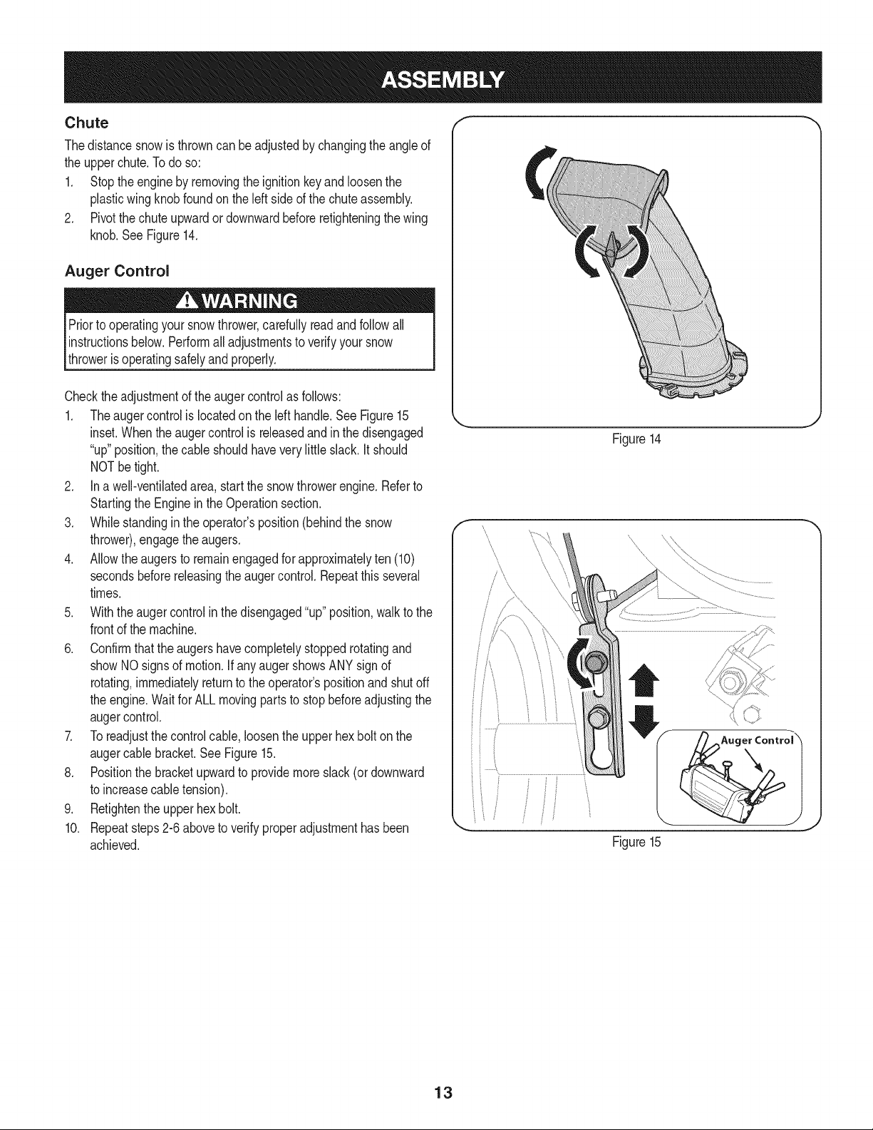
Chute f "_
Thedistancesnowis throwncan beadjustedby changingthe angleof
the upperchute.Todo so:
1. Stopthe engineby removingthe ignitionkeyandloosenthe
plasticwingknobfoundonthe left sideof the chuteassembly.
2. Pivotthe chuteupwardor downwardbeforeretighteningthewing
knob.See Figure14.
Auger Control
Priorto operatingyoursnowthrower,carefullyread andfollowall
instructionsbelow.Performall adjustmentsto verifyyoursnow
throweris operatingsafelyand properly.
Checktheadjustmentof the augercontrolas follows:
1. Theaugercontrolis locatedonthe left handle.See Figure15
inset.Whentheaugercontrolis releasedand in the disengaged
"up"position,the cableshouldhaveverylittle slack. It should
NOTbetight.
2. In a well-ventibtedarea,start the snowthrowerengine.Referto
Startingthe Engineinthe Operationsection.
3. Whilestandinginthe operator'sposition(behindthe snow
thrower),engagethe augers.
4. Allowtheaugersto remainengagedfor approximatelyten (10)
secondsbeforereleasingthe augercontrol.Repeatthisseveral
times.
5. Withtheaugercontrolin thedisengaged"up" position,walkto the
frontof the machine.
6. Confirmthatthe augershavecompletelystoppedrotatingand
showNOsignsof motion.If anyaugershowsANY signof
rotating,immediatelyreturnto the operator'spositionandshutoff
the engine.Waitfor ALL movingpartsto stopbeforeadjustingthe
augercontrol.
7. Toreadjustthecontrolcable,loosentheupperhexbolt onthe
augercablebracket.SeeFigure15.
8. Positionthe bracketupwardto providemoreslack(or downward
to increasecabletension).
9. Retightenthe upperhex bolt.
10. Repeatsteps2-6 aboveto verifyproperadjustmenthasbeen
achieved.
Figure14
\ \
\\
\
Figure15
J
13
f
Drive Control
Shift Lever
J Two=Way Chute Control (Joystick)
/
er Control
Gas Cap
\
AugerHousim
ChuteAssembly
\\\
\,
\
Clean Out
Tool
\
\
\
Augers
Skid Shoe
-Wheel Steering Control
Nluffler Recoil Starter
\ Handle
Primer \_ _ FUELLEVEL
Key
:lectric Start
Button
/ /
Oil Drain Electric Starter Outlet
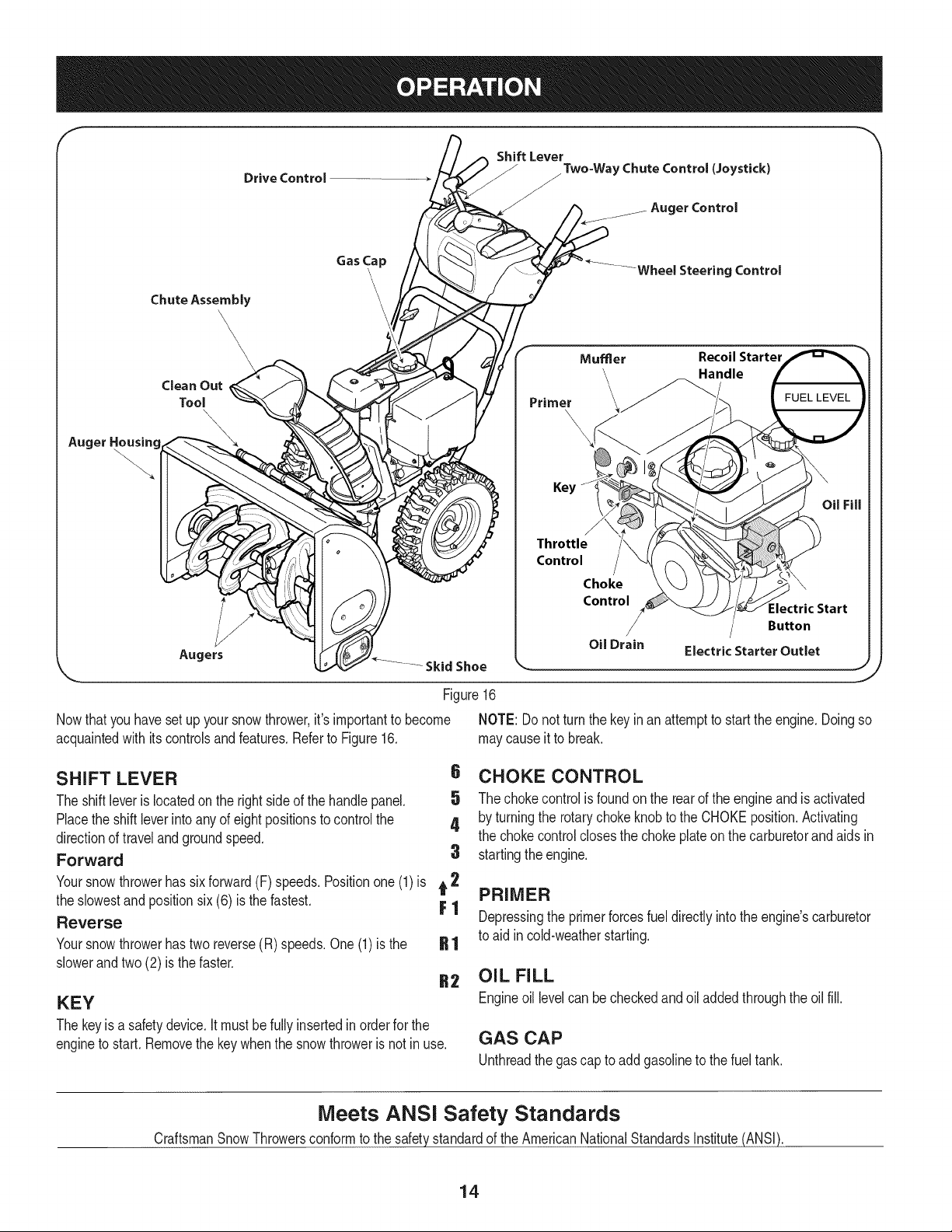
Figure16
Nowthat youhaveset up yoursnowthrower,it'simportantto become
acquaintedwith itscontrolsand features.Referto Figure16.
Throttle
Control
Choke
Control
,J
NOTE: Donot turnthe keyinan attemptto startthe engine.Doingso
maycauseit to break.
SHIFT LEVER
The shiftleverislocatedon the rightsideof the handle panel.
Placethe shiftleverintoanyof eightpositionsto controlthe
directionof travelandgroundspeed.
Forward
6 CHOKE CONTROL
5 The chokecontrolisfoundon the rearof the engineand isactivated
4 by turningthe rotarychokeknobto the CHOKEposition.Activating
the chokecontrolclosesthe chokeplateon thecarburetorand aids in
3 startingthe engine,
Yoursnowthrowerhas sixforward(F) speeds.Positionone (1)is t 2
the slowestand positionsix (6) is the fastest. F 1
Reverse
Yoursnowthrowerhastwo reverse(R) speeds.One (1) is the
slowerandtwo (2) is the faster.
KEY
The keyisa safety device.It mustbefully insertedin orderfor the
engineto start.Removethe keywhenthe snowthroweris notinuse.
PRIMER
Depressingthe primerforcesfueldirectlyintothe engine'scarburetor
to aid incold-weatherstarting.
OIL FILL
Engineoil levelcan be checkedandoil added throughthe oil fill.
GAS CAP
Unthreadthe gas capto add gasolineto thefuel tank.
Meets ANSi Safety Standards
CraftsmanSnowThrowersconformto the safetystandardof the AmericanNationalStandardsInstitute(ANSI).
14
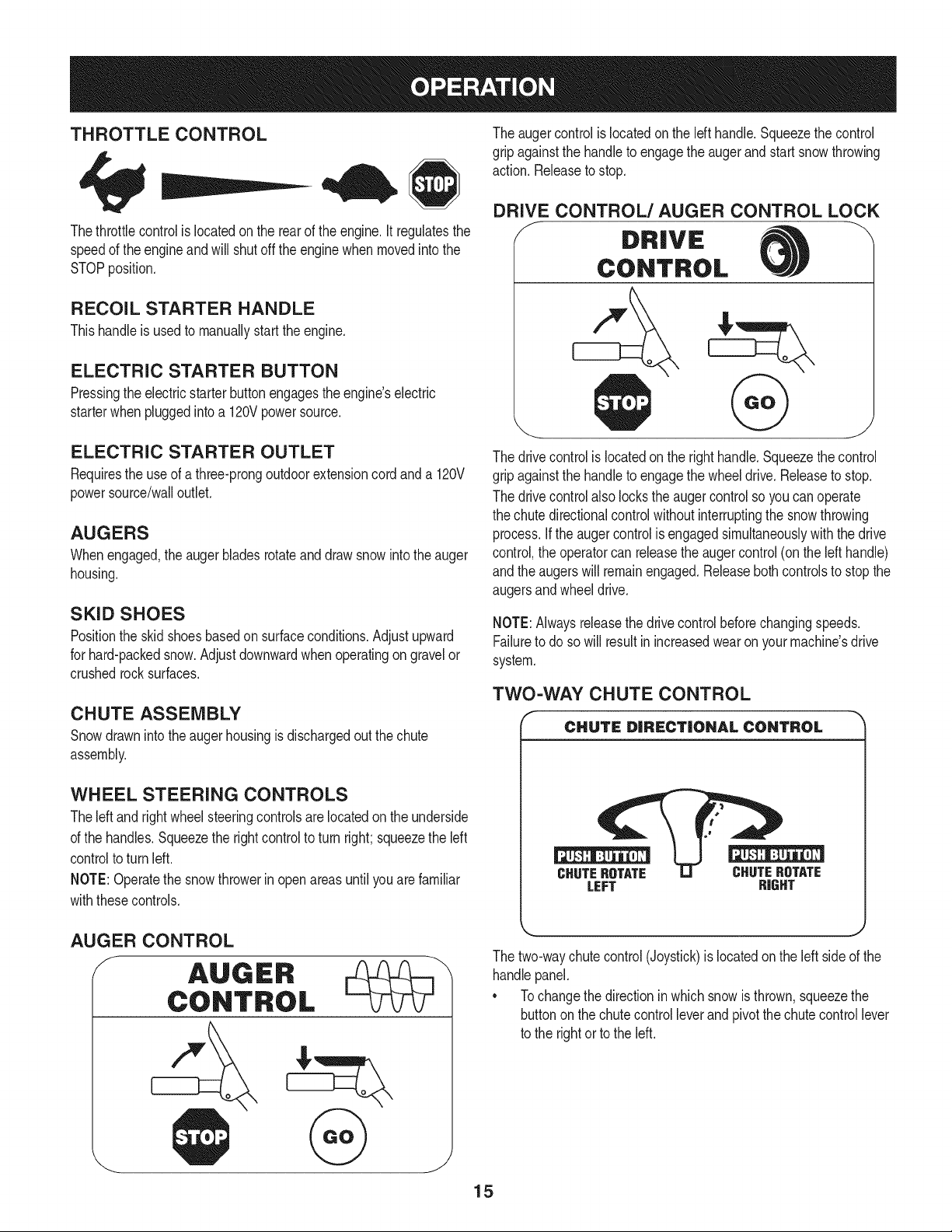
THROTTLE CONTROL
Thethrottlecontrolis locatedon the rearof the engine.It regulatesthe
speedof theengineandwill shutoff the enginewhenmovedintothe
STOPposition.
RECOIL STARTER HANDLE
Thishandleis usedto manuallystartthe engine.
ELECTRIC STARTER BUTTON
Pressingthe electricstarterbuttonengagesthe engine'selectric
starterwhenpluggedintoa 120Vpowersource.
ELECTRIC STARTER OUTLET
Requiresthe useof athree-prongoutdoorextensioncordanda 120V
powersource/walloutlet.
AUGERS
Whenengaged,the auger bladesrotateand drawsnowintothe auger
housing.
SKID SHOES
Positionthe skid shoesbasedon surfaceconditions.Adjustupward
for hard-packedsnow.Adjust downwardwhenoperatingon gravelor
crushedrocksurfaces.
CHUTE ASSEMBLY
Snowdrawninto theauger housingis dischargedout the chute
assembly.
WHEEL STEERING CONTROLS
Theleft and rightwheelsteeringcontrolsarelocatedon theunderside
of the handles.Squeezethe rightcontrolto turn right; squeezethe left
controlto turn left.
NOTE:Operatethe snowthrowerin openareasuntilyou arefamiliar
withthesecontrols.
The augercontrolis locatedon the lefthandle.Squeezethe control
gripagainstthe handleto engagethe augerand startsnowthrowing
action.Releaseto stop.
DRIVE CONTROL/AUGER CONTROL LOCK
DRIVE
CONTROL
The drivecontrolis locatedon the righthandle.Squeezethe control
gripagainstthe handleto engagethe wheeldrive.Releaseto stop.
The drivecontrolalso lockstheaugercontrolso youcan operate
the chutedirectionalcontrolwithoutinterruptingthe snowthrowing
process.If the augercontrolis engagedsimultaneouslywiththe drive
control,the operatorcan releasethe augercontrol(on the left handle)
andthe augerswill remainengaged.Releaseboth controlsto stopthe
augersandwheeldrive.
NOTE:Alwaysreleasethedrivecontrolbeforechangingspeeds.
Failureto do so will result in increasedwearon yourmachine'sdrive
system.
TWO-WAY CHUTE CONTROL
r
CHUTE DiRECTiONAL CONTROL
CHUTEROTATE CHUTEROTATE
LEFT RIGHT
AUGER CONTROL
_ J
The two-waychutecontrol(Joystick)is locatedon the left side of the
handlepanel.
* Tochangethe directionin which snowis thrown,squeezethe
buttononthe chutecontrol leverand pivotthe chutecontrol lever
to the rightorto the left.
15
CLEAN-OUT TOOL
Neveruseyourhandsto cleara cloggedchuteassembly.Shut
loft engineand remainbehindhandlesuntil allmovingpartshave
lstoppedbeforeusingtheclean-outtool to clearthe chuteassembly.
Thechuteclean-outtool is convenientlyfastenedto the rearof the
augerhousingwith a mountingclip. Shouldsnowandice become
lodgedin thechute assemblyduringoperation,proceedas followsto
safelycleanthechuteassemblyandchute opening:
1. Releaseboththe AugerControlandthe DriveControl.
2. Stopthe engineby removingthe ignitionkey.
3. Removethe clean-outtoolfromthe clip whichsecuresit to the
rearof the augerhousing.
4. Usethe shovel-shapedendof theclean-outtool to dislodgeand
scoopany snowand icewhich hasformedin andnear thechute
assembly.
5. Refastenthe clean-outtool to the mountingclip on the rear of
theaugerhousing,reinsertthe ignitionkeyand startthe snow
thrower'sengine.
6. Whilestandinginthe operator'sposition(behindthesnow
thrower),engagethe auger controlfora fewsecondsto clear any
remainingsnowand ice from thechuteassembly.
BEFORE STARTING ENGINE
Read,understand,and followall instructionsand warningson the
machineand in this manualbeforeoperating.
Oil
Theunit wasshippedwith oil inthe engine.Checkoil levelbefore
eachoperationto ensureadequateoil inthe engine.Forfurther
instructions,refertothe stepson page18.
NOTE:Besureto checkthe engineon a levelsurfacewith the engine
stopped.
1. Removethe oil fillercap/dipstickand wipethe dipstickclean.
2. insertthe cap/dipstickintothe oil filler neck,butdo NOTscrewit
in.
3. Removethe oil fillercap/dipstick,ifthe levelislow,slowlyadd
oil (5%30, with a minimumclassificationof SF/SG)untiloil level
registersbetweenhigh (H) and low(L).
NOTE:Do notoverfill.Overfillingwithoil mayresult inenginesmoking,
hardstartingor sparkplugfouling.
4. Replaceand tighten cap/dipstickfirmlybeforestartingengine.
Gasoline
Useautomotivegasoline(unleadedor low leadedto minimizecombus-
tionchamberdeposits)with a minimumof 87 octane.Gasolinewith
upto 10%ethanolor 15%MTBE(MethylTertiaryButylEther)canbe
used.Neveruseanoil/gasolinemixtureor dirtygasoline.Avoidgetting
dirt,dust,or waterin thefuel tank. DO NOTuse E85gasoline.
• Refuelin a well-ventilatedareawiththe enginestopped.Do not
smokeorallowflamesor sparksin the areawherethe engineis
refueledor wheregasolineisstored.
• Donot overfillthe fueltank.After refueling,makesurethe tank
cap is closedproperlyand securely.
• Be carefulnotto spillfuel whenrefueling.Spilledfuel or fuel vapor
mayignite,ifany fuelis spilled,makesurethe area isdry before
startingthe engine.
• Avoidrepeatedor prolongedcontactwithskinor breathingof
)or.
Useextremecarewhen handlinggasoline.Gasolineis extremely
flammableand thevaporsare explosive.Neverfuelthe machine
indoorsorwhilethe engineis hotor running.Extinguishcigarettes,
cigars,pipesandothersourcesof ignition.
1. Cleanaroundfuel fill beforeremovingcap to fuel.
2. A fuel levelindicatoris locatedin the fueltank. See Figure15
inset. Becarefulnotto overfill.Filltank untilfuel reachesthe fuel
level indicatorto allowspacefor fuel expansion.
STARTING THE ENGINE
Alwayskeep handsandfeet clearof movingparts. Donot usea
pressurizedstartingfluid.Vaporsare flammable.
NOTE:Allowthe engineto warmupfor a fewminutesafter starting.
The enginewill notdevelopfull poweruntilit reachesoperating
temperatures.
1. Makecertainboththe augercontrolanddrivecontrolarein the
disengaged(released)position.
2. insertkeyinto slot. Makesureit snapsintoplace.Donot attempt
to turn the key.
NOTE: Theenginecannotstartwithoutthe keyfullyinsertedintothe
ignitionswitch.
Electric Starter
The optionalelectricstarteris equippedwith a groundedthree-wire
powercordandplug,and is designedto operateon 120voltAC
householdcurrent.It mustbe usedwitha properlygroundedthree-
prongreceptacleat all timesto avoidthe possibilityof electricshock.
Followall instructionscarefullyprior to operatingtheelectricstarter.
DONOTuse electricstarterinthe rain.
Determinethat yourhome'swiringis a three-wiregroundedsystem.
Aska licensedelectricianif you arenotcertain.
Ifyou havea groundedthree-prongreceptacle,proceedas follows.
Ifyou donot havethe properhousewiring,DONOTusethe electric
starterunderanyconditions.
1. Plugthe extensioncord intothe outletlocatedon the engine's
surface.Plugthe otherendof extensioncord intoa three-prong
120-volt,grounded,AC outletin a well-ventilatedarea.
16
2. Movethrottlecontrolto FAST(rabbit)_J_" position.
3. Movechoketo the CHOKEI,'_1 position(coldenginestart).If
engineis warm,placechokein RUNposition.
4. Pushprimerthree (3)times,makingsureto covervent hole in
primerbulbwhen pushing.If engineis warm,pushprimeronly
once.Alwayscover ventholewhenpushing.Coolweathermay
requireprimingto be repeated.
5. Pushstarterbuttonto start engine.Oncethe enginestarts,im-
mediatelyreleasestarterbutton.Electricstarteris equippedwith
thermaloverloadprotection;systemwill temporarilyshut-downto
allowstarterto cool if electricstarterbecomesoverloaded.
6. As theenginewarms,slowlyrotatethe chokecontrolto RUN
position.If the enginefalters,restartengineandrun with choke
at half-chokepositionfor a shortperiodof time,andthen slowly
rotatethe chokeinto RUNposition.
7. Afterengineis running,disconnectpowercordfrom electric
starter.Whendisconnecting,alwaysunplugthe endat the wall
outletbeforeunpluggingtheoppositeendfrom the engine.
Recoil Starter
TO ENGAGE DRIVE
1. Withthe throttlecontrolinthe Fast(rabbit) position,moveshift
leverinto one of the six forward(F) positionsor tworeverse(R)
positions.Selecta speedappropriatefor the snowconditionsand
a paceyou'recomfortablewith.
NOTE: When selectinga DriveSpeed,use the slowerspeedsuntil
you arecomfortableandfamiliarwiththe operationof the snow
thrower.
2. Squeezethe drivecontrolagainstthe handleandthe snow
throwerwill move.Releaseit anddrive motionwill stop.
NOTE:NEVERrepositionthe shiftlever(changespeedsordirection
of travel)withoutfirst releasingthe drivecontrol and bringingthe snow
throwerto a completestop.Doingsowill resultin prematurewearto
the snowthrower'sdrivesystem.
TO ENGAGE AUGERS
1. Toengagethe augersandstartthrowingsnow,squeezethe
augercontrolagainstthe left handle.Releaseto stop theaugers.
Do notpullthe starterhandlewhilethe enginerunning.
1. Movethrottlecontrolto FAST(rabbit)_J_ position.
2. Movechoketo the CHOKEI_¢1 position(coldenginestart).If
engineis warm,placechokein RUNposition.
3. Pushprimerthree (3)times,makingsureto covervent hole when
pushing.Ifengine iswarm,push primeronlyonce.Alwayscover
ventholewhen pushing.Coolweathermayrequireprimingto be
repeated.
4. Pullgentlyonthe starterhandleuntil it beginsto resist,then
pullquicklyandforcefullyto overcomethe compression.Engine
shouldstart.Donot releasethe handleandallow it to snapback.
ReturnropeSLOWLYto originalposition.If required,repeatthis
step.
5. As theenginewarms,slowlyrotatethe chokecontrolto RUN
position.If the enginefalters,restartengineandrun with choke
at half-chokepositionfor a shortperiodof time,andthen slowly
rotatethe chokeinto RUNposition.
To avoidunsupervisedengineoperation,neverleavethe machine
unattendedwiththe engine running.Turnthe engineoffafteruse and
removekey.
STOPPING THE ENGINE
Afteryouhavefinishedsnow-throwing,run enginefora few minutes
beforestoppingto helpdry offany moistureonthe engine.
1. Movethrottlecontrolto OFFposition.
2. Removethekey.Removingthe key will reducethe possibilityof
unauthorizedstartingof the enginewhileequipmentis notin use.
Keepthe keyin a safeplace.The enginecannotstart withoutthe
key.
3. Wipeany moistureawayfromthe controlson theengine.
17
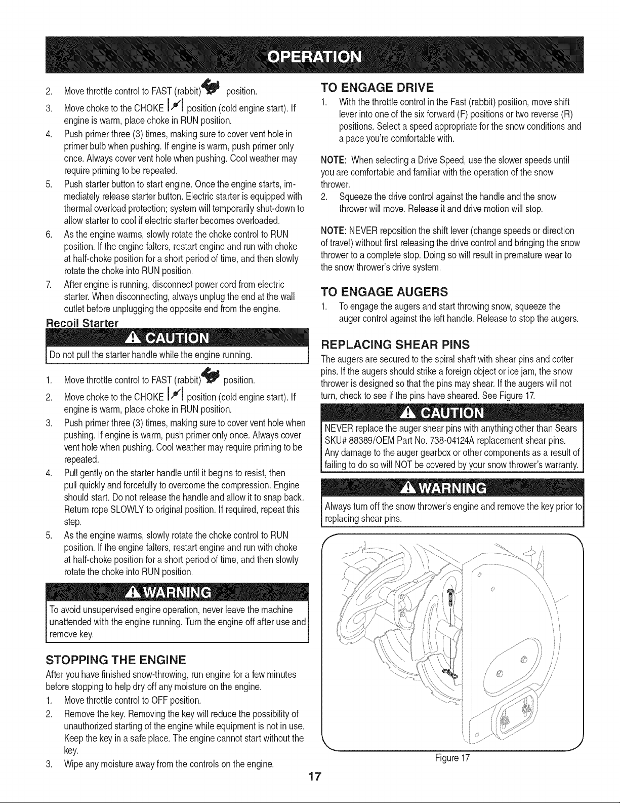
REPLACING SHEAR PiNS
The augersare securedto the spiralshaftwith shearpins andcotter
pins.If the augersshouldstrikeaforeignobject or ice jam, the snow
throweris designedso that the pins mayshear.If theaugerswill not
turn,checkto see if the pins havesheared.SeeFigure17.
NEVERreplacethe augershearpinswith anythingotherthan Sears
SKU#88389/0EM PartNo. 738-04124Areplacementshearpins.
Anydamageto theaugergearboxor other componentsas a resultof
failingto do sowill NOTbe coveredbyyour snowthrower'swarranty.
Alwaysturn off thesnowthrower'sengineand removethe key priorto
replacing shear pins.
'i
//
Figure17
MAINTENANCE SCHEDULE
Beforeperforminganytypeofmaintenance/service,disengageall
controlsand stoptheengine.Waituntilall movingpartshavecometo
acompletestop.Disconnectsparkplugwireandgroundit againstthe
enginetopreventunintendedstarting.Alwayswearsafetyglassesduring
operationor whileperforminganyadjustmentsor repairs.
EachUseandevery5
hours
1st5 hours
Annuallyor 25 hours
Annuallyor 50 hours
Annuallyor 100hours
BeforeStorage
1. Engineoil level
2. Looseor missinghardware
3. Unitandengine.
1. Engineoil
1. Sparkplug
2. Controllinkagesandpivots
3. Wheels
4. GearshaftandAugershaft
1. Engineoil
1. Sparkplug
1. Fuelsystem
Followthe maintenanceschedulegiven below.This chartdescribes
serviceguidelinesonly.Usethe ServiceLog columnto keeptrackof
completedmaintenancetasks.To locate the nearest Sears Service
Centeror to scheduleservice,simplycontactSearsat
1-800-4-MY-HOME®.
1. Check
2. Tightenor replace
3. Clean
1. Change
1. Check
2. Lubewithlight oil
3. Lubewithmultipurposeautogrease
4. Lubewithlight oil
1. Change
1. Change
1. Runengineuntilit stopsfromlack
d fuel
ENGINE MAINTENANCE
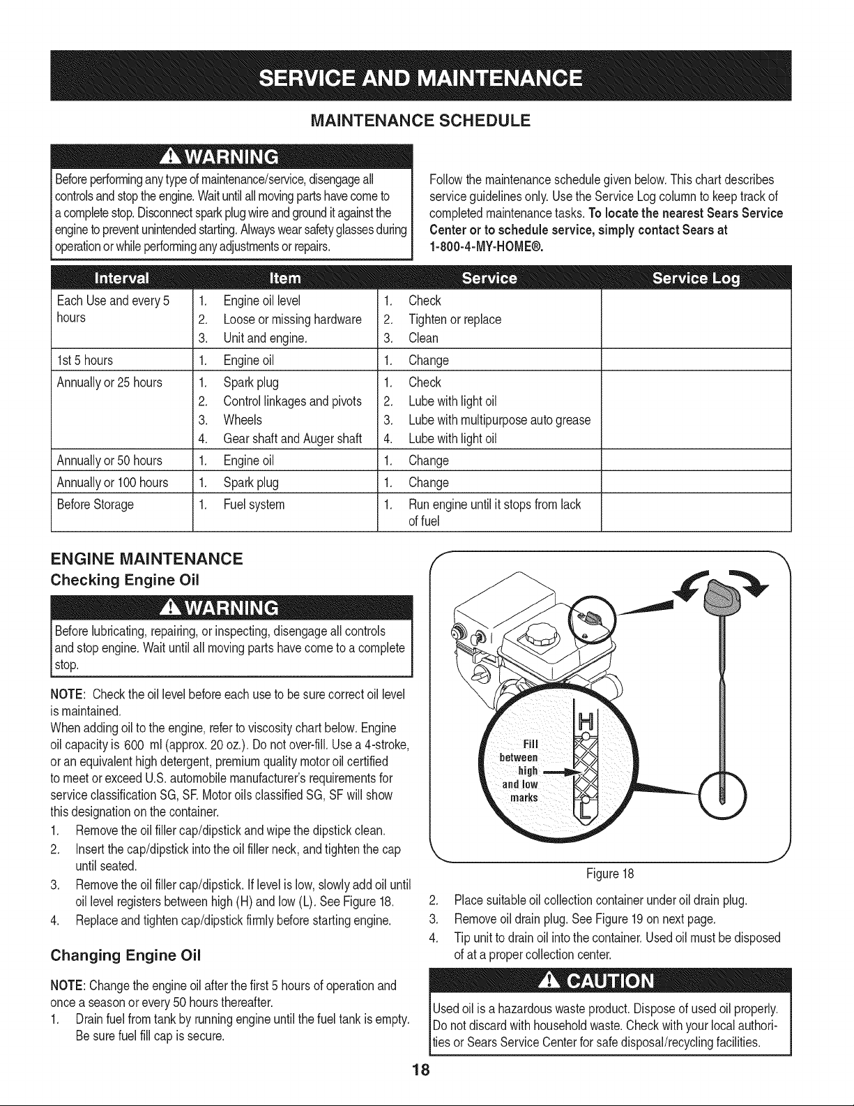
Checking Engine Oil
Beforelubricating,repairing,or inspecting,disengageall controls
Iandstopengine.Waituntilall movingpartshavecometo a complete
_stop.
NOTE: Checktheoil levelbeforeeachuseto be surecorrectoil level
is maintained.
Whenaddingoilto the engine,referto viscositychart below.Engine
oilcapacityis 600 ml (approx.20 oz.). Donot over-fill.Usea 4-stroke,
oran equivalenthighdetergent,premiumqualitymotoroil certified
to meetorexceedU.S.automobilemanufacturer'srequirementsfor
serviceclassificationSG, SR MotoroilsclassifiedSG, SFwill show
thisdesignationonthe container.
1. Removethe oil fillercap/dipstickand wipethe dipstickclean.
2. Insertthe cap/dipstickintothe oilfiller neck,andtightenthe cap
until seated.
3. Removethe oil fillercap/dipstick.If levelis low, slowlyadd oil until
oil levelregistersbetweenhigh(H) andlow (L). See Figure18.
4. Replaceand tighten cap/dipstickfirmlybeforestartingengine.
Changing Engine Oil
NOTE:Changethe engineoil afterthe first5 hoursof operationand
oncea seasonor every50 hoursthereafter.
1. Drainfuelfromtankby runningengineuntilthe fuel tankis empty.
Besurefuel fill cap is secure.
J
Figure18
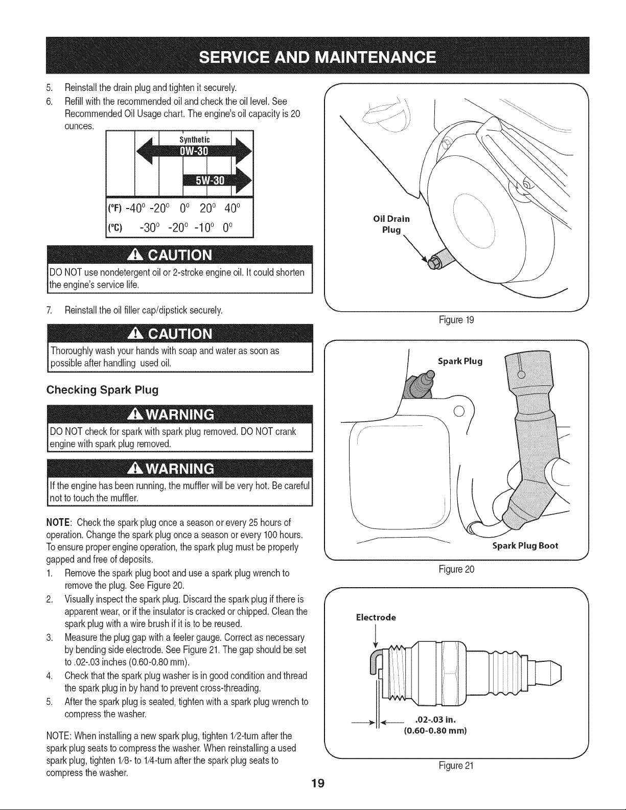
2. Placesuitableoil collectioncontainerunderoil drainplug.
3. Removeoil drain plug.See Figure19on nextpage.
4. Tip unit to drainoil intothe container.Usedoil mustbedisposed
of at a propercollectioncenter.
Usedoil is a hazardouswasteproduct.Disposeof usedoil properly.
IDo notdiscardwithhouseholdwaste.Checkwithyour localauthori-
lties or SearsService Centerfor safe disposal/recyclingfacilities.
18
.
6.
Reinstallthe drain plugandtightenit securely.
Refillwiththe recommendedoil andcheckthe oil level.See
RecommendedOil Usagechart.Theengine'soil capacityis 20
ounces.
i u
[
(%-40 °-20 o 0o 200 400
("c) -300 -200 -10° 0°
DO NOTuse nondetergentoilor 2-strokeengineoil. Itcould shorten
the engine'sservicelife.
Oil Drain
Plug
7. Reinstallthe oilfillercap/dipsticksecurely.
Figure19
Thoroughlywashyour handswith soap andwateras soonas
possibleafterhandling usedoil.
Checking Spark Plug
DO NOTcheckfor sparkwithsparkplug removed.DO NOTcrank
enginewith sparkplug removed.
Ifthe enginehas beenrunning,the mufflerwill be very hot.Becareful
notto touchthe muffler.
NOTE: Checkthe sparkplugoncea seasonor every25hoursof
operation.Changethe sparkplug oncea seasonor every100hours.
Toensureproperengineoperation,the sparkplugmustbe properly
gappedandfreeof deposits.
1. Removethespark plug bootanduse a sparkplug wrenchto
removethe plug.See Figure20.
2. Visuallyinspectthe sparkplug.Discardthe sparkplugif thereis
apparentwear,or if the insulatoris crackedor chipped.Cleanthe
sparkplugwith a wirebrush if it is to be reused.
3. Measurethe plug gap witha feelergauge.Correctas necessary
by bendingsideelectrode.See Figure21.The gapshouldbe set
to .02-.03inches(0.60-0.80ram).
4. Checkthatthe sparkplugwasheris ingoodconditionandthread
the sparkplugin by handto preventcross-threading.
5. Afterthesparkplugis seated,tightenwith a sparkplugwrenchto
compressthe washer.
NOTE:Wheninstallinga newsparkplug,tighten1/2-turnafterthe
sparkplugseatsto compressthe washer.Whenreinstallinga used
sparkplug,tighten1/8-to 1/4-turnafterthe sparkplug seatsto
compressthe washer.
19
Spark Plug
O
J
Figure20
Electrode
.02-.03 in.
{0.60-0.80 ram)
Figure21
hotandcan ine.
LUBRICATION
Gear Shaft
Thegear(hex)shaft shouldbe lubricatedat leastoncea seasonor
afterevery25 hoursof operation.
1. Topreventspillage,removeall fuel fromtank by runningengine
until it stops.
2. Carefullypivotthe snowthrowerupand forwardso that it restson
theaugerhousing.
3. Removethe lowerframecover fromthe undersideof the snow
throwerby removingthe self-tappingscrewswhich secureit.
4. Applya lightcoatingof engineoil (or 31in-1oil) to the hexshaft.
SeeFigure22.
NOTE:Whenlubricatingthe hexshaft, be carefulnotto get any oilon
thealuminumdriveplateor rubberfrictionwheel.Doingsowill hinder
the snowthrower'sdrive system.Wipeoff anyexcessor spilledoil.
Wheels
At leastoncea season,removebothwheels.Cleanandcoattheaxles
witha multipurposeautomotivegreasebeforereinstallingwheels.
Auger Shaft
At leastoncea season,removethe shearpinson augershaft.Spray
lubricantinsideshaft,andaroundthe spacersandflangebearings
foundat eitherendof the shaft.See Figure23.
SHAVE PLATE AND SKID SHOES
The shaveplateand skidshoeson the bottomof the snowthrowerare
subjectto wear.They shouldbecheckedperiodicallyand replaced
whennecessary.
NOTE:Theskidshoeson this machinehavetwowearedges.When
onesidewearsout,theycan be rotated1800to usethe otheredge.
To removeskidshoes:
1. Removethe twocarriagebolts,washers(if equipped),andhex
flangenutsthat secureeach skid shoeto the snowthrower.
2. Reassemblenew skid shoeswith the fourcarriagebolts(two on
eachside),washers,andhex flangenuts.Referto Figure24.
To removeshaveplate:
1. Removethe carriageboltsand hexnuts whichattachit to the
snowthrowerhousing.
2. Reassemblenew shaveplate,makingsureheadsof carriage
boltsareto the insideof housing.Tightensecurely.SeeFigure24.
O i
)
J' "?X
/ .... )
{;:7,_"
7/'................
Figure22
/
/
/
f
Figure23
..............'L i
7j y_........ o i J,_J
7i ......... ;7....... _,
NOTE:Augersnotshown for clarity.
Figure24
J
2O
ADJUSTMENTS
Shift Cable
If thefull rangeof speeds(forwardandreverse)cannotbe achieved,
referto the figureto the rightandadjustthe shift cableas follows:
1. Placethe shiftleverin thefastest forward speedposition(F6).
2. Loosenthe hex nuton the shiftcable indexbracket.SeeFigure
25.
3. Pivotthe bracketdownwardto takeup slack in the cable.
4. Retightenthehex nut.
Drive Control
Whenthedrivecontrolis releasedand in thedisengaged"up"position,
the cableshouldhavevery little slack.It shouldNOTbe tight. Also,
if thereis excessiveslackin thedrive cableor if the unitexperiences
intermittentdrivewhileusing,the cable mayneed to be adjusted.
Checktheadjustmentof the drivecontrolas follows:
1. Withthedrivecontrolreleased,pushthe snowthrowergently
forward.The unitshouldroll freely.
2. Engagethe drivecontroland gently attemptto pushthe snow
throwerforward.Thewheelsshouldnotturn.The unitshouldnot
rollfreely.
3. Withthedrivecontrolreleased,movethe shift leverbackand
forthbetweenthe R2positionandthe F6 positionseveraltimes.
Thereshouldbeno resistancein the shiftlever.
4. If anyof the abovetests failed,the drivecable is in needof adjust-
ment.Proceedas follows:
a. Shutoff theengineas instructedinthe Operationsection.
b. Loosenthe lowerhexbolt onthe drivecable bracket.See
Figure26.
c. Positionthe bracketupwardto providemoreslack(or
downwardto increasecabletension).
d. Retightenthe lowerhex boltand repeatsteps1 through4.
f
.........
J
Chute Control Rod
Toachievemorechutecontrolrodengagementin the input shaftunder
the handlepanelshownin Figure7 inthe Assemblysection,the chute
controlrodwill haveto beadjusted.Referto Figure27.
Toadjustthis rod,proceedas follows:
1. Removethecotterpin fromthe holeclosestto the chutecontrol
headon thechute controlinput.
2. Pulloutthe chutecontrolroduntilthe holein it lines up with the
otherholeinthe chute controlinput.
3. Reinsertthe cotterpinthroughthis holeand thechute controlrod.
Figure26
J
/
/ ,
\
\
J
Figure27
21
Auger Control
Referto the Assemblysectionfor instructionson adjustingtheauger
controlcable.
Skid Shoes
Referto the Assemblysectionfor instructionson adjustingthe skid
shoes.
BELT REPLACEMENT
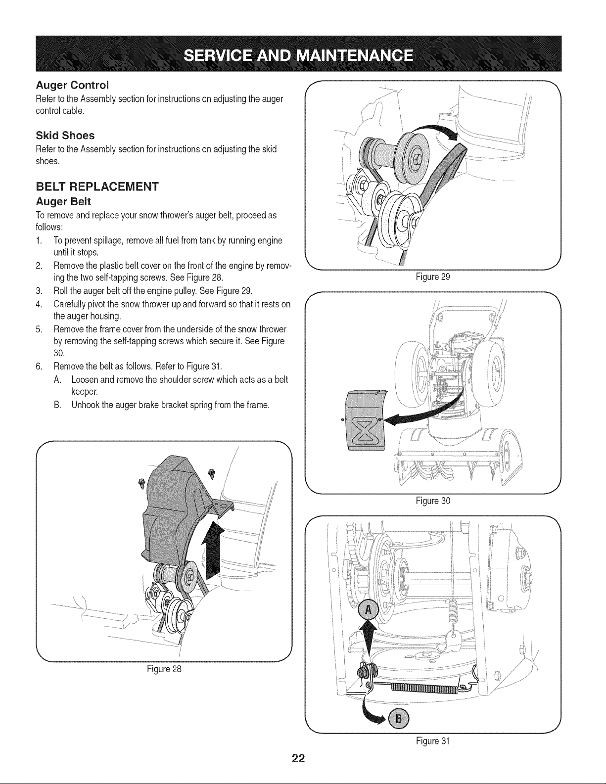
Auger Belt
To removeandreplaceyoursnow thrower'sauger belt, proceedas
follows:
1. Topreventspillage,removeall fuel fromtank by runningengine
until itstops.
2. Removethe plasticbelt coveron the frontof the engineby remov-
ingthe two self-tappingscrews.SeeFigure28.
3. Rollthe augerbeltoff theenginepulley.See Figure29.
4. Carefullypivotthe snowthrowerupand forwardso that itrestson
theaugerhousing.
5. Removethe framecoverfromthe undersideof the snowthrower
by removingthe self-tappingscrewswhich secureit. SeeFigure
30.
6. Removethe beltas follows.Referto Figure31.
A. Loosenand removethe shoulderscrewwhichactsas a belt
keeper.
B. Unhookthe augerbrakebracketspringfromthe frame.
f
Figure28
J
Figure29
J
Figure30
f
.....i
_jz:.................
22
Figure31
J
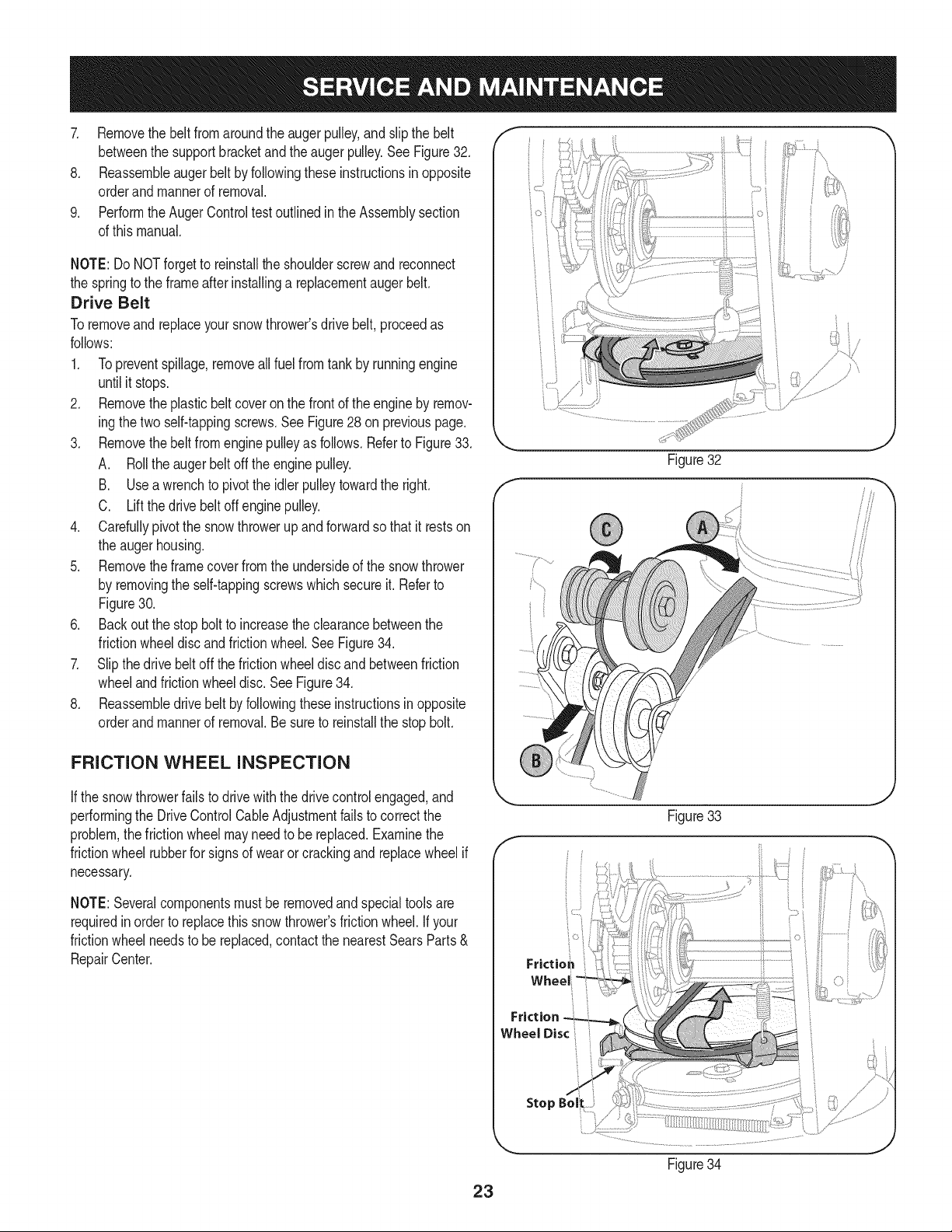
7. Removethebeltfromaroundtheaugerpulley,andslipthebelt
betweenthesupportbracketandtheaugerpulley.SeeFigure32.
8. Reassembleaugerbeltbyfollowingtheseinstructionsinopposite
orderandmannerofremoval.
9. PerformtheAugerControltestoutlinedintheAssemblysection
ofthismanual.
NOTE:DoNOTforgettoreinstalltheshoulderscrewandreconnect
thespringtotheframeafterinstallingareplacementaugerbelt.
Drive Belt
Toremoveand replaceyoursnowthrower'sdrivebelt,proceedas
follows:
1. Topreventspillage,removeallfuel fromtankby runningengine
untilit stops.
2. Removetheplasticbelt coveronthe frontof the engineby remov-
ingthe two self-tappingscrews.See Figure28 on previouspage.
3. Removethebelt fromenginepulleyas follows.Referto Figure33.
A. Rollthe augerbeltoff theengine pulley.
B. Useawrenchto pivotthe idlerpulleytowardthe right.
C. Liftthe drivebelt off enginepulley.
4. Carefullypivotthe snowthrowerupand forwardsothat itrestson
the augerhousing.
5. Removetheframecoverfromthe undersideof the snowthrower
by removingthe self-tappingscrewswhich secureit. Referto
Figure30.
6. Backoutthe stopbolt to increasethe clearancebetweenthe
frictionwheeldiscandfrictionwheel.SeeFigure34.
7. Slipthe drivebelt offthe frictionwheeldiscandbetweenfriction
wheelandfrictionwheeldisc.SeeFigure34.
8. Reassembledrive beltby followingthese instructionsinopposite
orderand mannerof removal.Be sureto reinstallthe stopbolt.
FRICTION WHEEL INSPECTION
If the snowthrowerfailsto drivewith thedrivecontrolengaged,and
performingthe DriveControlCableAdjustmentfailsto correctthe
problem,the frictionwheelmayneedto be replaced.Examinethe
frictionwheelrubberfor signsof wearor crackingand replacewheelif
necessary.
NOTE:Severalcomponentsmustbe removedandspecialtoolsare
requiredinorder to replacethis snowthrower'sfrictionwheel.If your
frictionwheelneedsto be replaced,contactthe nearestSearsParts&
RepairCenter.
iO i
Figure32
///
f
Frictio_
Friction
Wheel Disc
Stop
Figure33
.J
Figure34
23
Ifthe snowthrowerwillnot be usedfor30 daysor longer,or if it is the endof the snowseasonwhenthe lastpossibilityof snowis gone,the
equipmentneedsto bestoredproperly.Followstorageinstructionsbelowto ensuretop performancefromthe snowthrowerfor manymoreyears.
PREPARING ENGINE
Enginesstoredover30 daysneedto bedrainedof fuel to prevent
deteriorationandgumfromforminginfuel systemor on essential
carburetorparts.If thegasolinein yourenginedeterioratesduring
storage,youmay needto havethe carburetor,andotherfuel system
components,servicedor replaced.
1. Removeall fuel fromtank by runningengineuntil it stops.Donot
attemptto pourfuel fromthe engine.
2. Changethe engineoil.
3. Removesparkplugand pour approximately1 oz. (30 rnl)of clean
engineoil intothe cylinder.Pullthe recoilstarterseveraltimesto
distributetheoil, and reinstallthe sparkplug.
4. Cleandebrisfromaroundengine,andunder,around,and behind
muffler.Applya lightfilmof oilon anyareasthat are susceptible
to rust.
• Storeina clean,dry andwellventilatedareaawayfrom anyap-
pliancethat operateswithaflameor pilotlight, such as a furnace,
waterheater,or clothesdryer.Avoidany areawitha spark
producingelectricmotor,or wherepowertoolsareoperated.
Neverstoresnowthrowerwithfuel in tank indoorsor inpoorlyventi-
latedareas,wherefuel fumesmay reachan openflame,sparkor pilol
lightas ona furnace,waterheater,clothesdryer orgas appliance.
• If possible,avoidstorageareaswithhigh humidity.
• Keepthe enginelevelin storage.Tiltingcan causefuel oroil
leakage.
PREPARING SNOW THROWER
Whenstoringthe snowthrowerin an unventilatedormetal stor-
age shed,careshouldbe takento rustprooftheequipment.Using
a light oil or silicone,coat theequipment,especiallyanychains,
springs,bearingsand cables.
• Removealldirt fromexteriorof engineandequipment.
• Followlubricationrecommendations.
• Storeequipmentin a clean,dry area.
• Inflatethe tiresto the maximumPSi. Referto tiresidewall.
24
Enginefailsto start
Enginerunningerratically/
inconsistentRPM(huntingor
surging)
Excessivevibration
Lossof power
Unitfailsto propelitself
Unitfailsto dischargesnow
1. Chokecontrolnot inCHOKEposition.
2. Sparkplugwire disconnected.
3. Faultysparkplug.
4. Fueltankemptyor stalefuel.
5. Enginenot primed.
6. Keynot inserted.
7. Extensioncordnot connected(when
usingelectricstartbutton,on modelsso
equipped).
1. EnginerunningonCHOKE.
2. Stalefuel.
3. Waterordirt infuel system.
4. Over-governedengine.
1. Loosepartsor damagedauger.
1. Sparkplugwire loose.
2. Gascap ventholeplugged.
1. Drivecable inneedof adjustment.
2. Drivebelt looseor damaged.
3. Wornfrictionwheel.
1. Chuteassemblyclogged.
2. Foreignobjectlodgedin auger.
3. Augercablein needof adjustment.
4. Augerbelt looseordamaged.
5. Shearpin(s) sheared.
1. Chuteassembledincorrectly.
1. Movechokecontrolto CHOKEposition.
2. Connectwireto sparkplug.
3. Clean,adjustgap,or replace.
4. Filltankwith clean,freshgasoline.
5. Primeengineas instructedin the OperationSection.
6. Insertkeyfully intothe switch.
7. Connectoneend of the extensioncordto the electric
starteroutletandthe otherend to a three-prong
120-volt,grounded,ACoutlet.
1. Movechokecontrolto RUNposition.
2. Filltankwith clean,freshgasoline.
3. Drainfueltankby runningengineuntil it stops.Refill
withfreshfuel.
4. ContactyourSearsParts& RepairCenter.
1. Stopengineimmediatelyand disconnectsparkplug
wire.Tightenall boltsand nuts.Ifvibrationcontinues,
haveunit servicedbya SearsParts& RepairCenter.
1. Connectandtightenspark plugwire.
2. Removeiceand snowfrom gascap. Becertainvent
holeis clear.
1. Adjustdrivecontrolcable.Referto Serviceand
Maintenancesection.
2. Replacedrive belt. Referto Serviceand Mainte-
nancesection.
3. Havefrictionwheelreplacedat a SearsParts &
RepairCenter.
1. Stopengineimmediatelyand disconnectsparkplug
wire.Cleanchuteassemblyandinsideof auger
housingwith clean-outtoolor a stick.
2. Stopengineimmediatelyand disconnectsparkplug
wire.Removeobjectfrom augerwith clean-outtool
ora stick.
3. Adjustaugercontrolcable.Referto Assembly
section.
4. Replaceauger belt. Referto Serviceand Mainte-
nancesection.
5. Replacewith newshearpin(s).
Chutefailsto easily rotate 180 1. Disassemblechutecontroland reassembleas
degrees directedinthe Assemblysection.
NEED HORE HELP?
Yot,Fttfind. th_ answer a!ld mo_e on ma_age_y_ifeocom _ for free]
Find this and att your other product manua[s ontine.
Get answers from our team of home experts.
Get a personalized maintenance p[an for your home.
Find information and tools to he[p with home projects.
managemylife
b_e'_g_t_/_eyeu by Sea_s
25
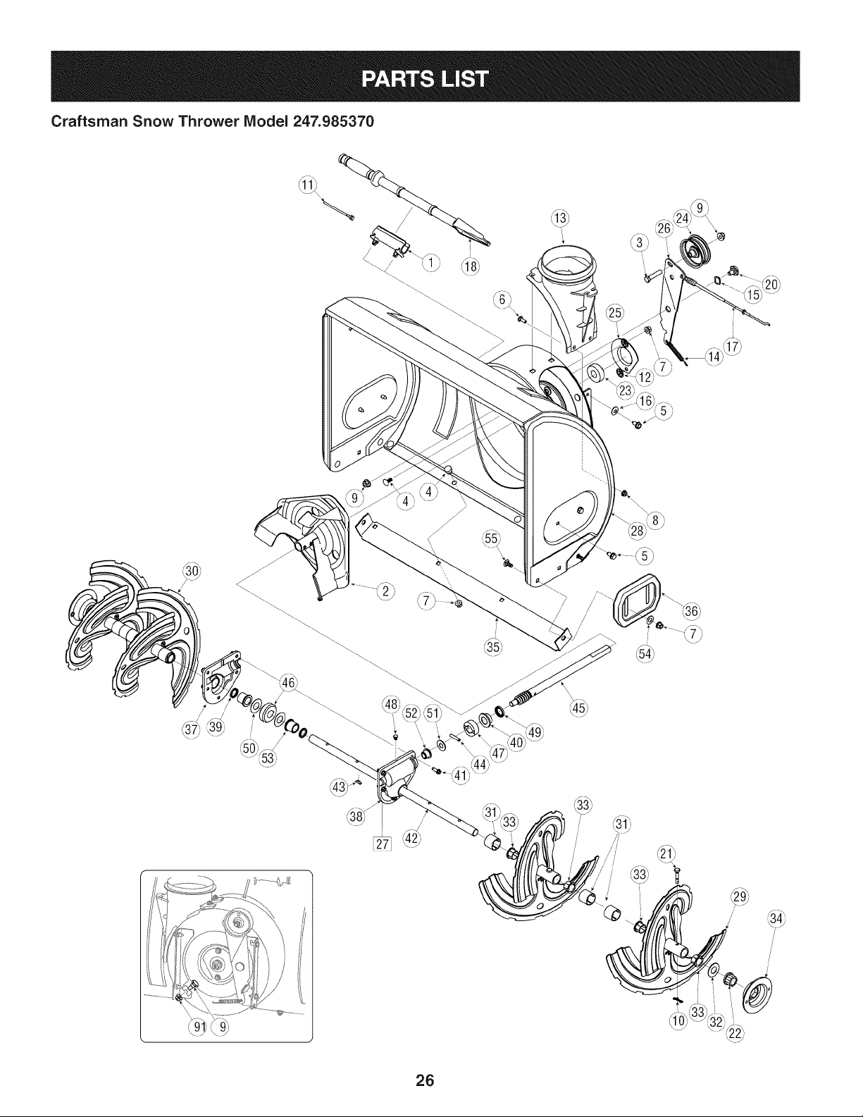
Craftsman Snow Thrower IViodel 247.985370
!
i
26
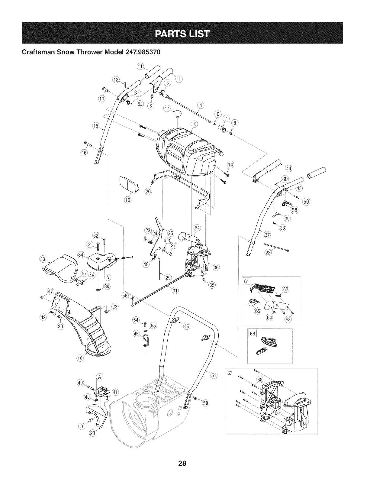
Craftsman Snow Thrower IViodel 247.985370
D = 0 0
731-2635 SnowRemovalToolMount
2. 684-04057A-0637 ImpellerAssembly,12"Dia.
3. L710-0347 LHexScrew,3/8-16,1.75,Gr5
4. 710-0451 Bolt,Carriage,5/16-18,.750Grl
5. 710-04484 Screw, 5/16-18,0.750
6. 710-0703 Screw,Carriage,1/4-20,.750,Gr5
7. 712-04063 Nut, FlangeLock,5/16-18,Nylon
8. 712-04064 Nut, FlangeLock,1/4-20,Nylon
9. 712-04065 Nut, FlangeLock,3/8-16,Nylon
10. 714-04040 CotterPin,Bow-tie
11. J 725-0157 l Cable,Tie, 3/16x .05x 7.4
12. 926-04012 Nut, Push-on,.25 Dia
13. 731-07525 Chute,Adapter5" Dia
14. 732-04460 Spring,Extension,.38OD x 4.59
15. 736-0174 Washer,Wave,.625x .885x .015
16. 736-0242 Washer,Bell, .340x .872x .060
17. 946-04230A ClutchCable,Auger,47.23"
18. 931-2643 SnowRemovalTool
19. .738-0143 _ Screw,Shoulder,.498x .34,3/8-16
20. 938-0281 Screw,Shoulder,.625x .17,3/8-16
21. 738-04124A ShearPin, .25x 1.50
22. 941-0245 Bearing,HexFlangex .75ID
23. 941-0309 Bearing,Ball,.75 IDx 1.85OD
24. 756-04224 Flat Pulley,Idler, 2.75OD
25. 790-00075 Housing,Bearing,1.85ID
26. 790-00080B Bracket,Auger Idlerw/Brake
27. J 918-04172B J GearboxAssembly,Auger,26"
28. 684-04264-4044 HousingAssembly,Auger26"
684-04107-0637
30. 684-04108-0637
31. 731-04870
32. 736-0188
33. 741-0493A
34. 790-00087A-0637
35. 790-00121-4044
36. 731-06439
37. 918-0123A
38. 918-0124A
39. 921-0338
40. 741-0662
41. 710-0642
42. 711-04284
D = O O
SpiralAssembly,LH
SpiralAssembly,RH
Spacer,1.25OD x .75ID x 1.00
Washer,Flat,.76x 1.49x .06
Bushing,Flange,.80ID x .91OD
Housing,1"HexBearing
ShavePlate,2.25 x 25.66
SlideShoe
Housing,Auger,RH Reduced
Housing,Auger,LH Reduced
Seal,Oil, .750x 1.00x .125
Bearing,Flange,.75x 1.0x .59
Screw,Self-tapping,1/4-20,0.750
Axle,Auger,26"
43. 914-0161 Key,Hi-pro3/16x 5/8
44. 715-04021 Pin, Dowel,.25 ODx 1.2
45. 917-04126 Shaft,Worm.75OD
46. 917-04861 Gear,Worm20T
47. 718-04071 Collar,Thrust
48. 721-0325 Plug, 1/4x .437
49. 721-0327 Seal,Oil, .75x 1x .131
50. 936-0351 Washer,Flat,.760ID x 1.50D
51. 736-3084 Washer,Flat,.51x 1.12
52. 741-0663 Bearing,Flange,.75x 1.0x .925
53. 741-0661A Bearing,Flange,.75x 1.00x .975
54. 936-0159 Washer,Fiat,.349x .879x .063
55. 710-0276 Screw,Carriage,5/16-18x 1.00
27
Craftsman Snow Thrower Model 247.985370
@
28
Craftsman Snow Thrower IViodel 247.985370
684-04112C HandleEngagementAssemblyRH
2. 738-04367 FlangeShoulderScrew
3. 731-04894D LockPlate
4. 684-04250 PivotRod
5. 935-0199A RubberBumper
6. 710-3069 Screw,1/4-20x .500
7. 731-04896B ClutchLock Cam
8. 712-04081A ShoulderNut, 1/4-20
9. 710-0627 HexScrew,5/16-24x .750
10. 731-06440A LowerChute
11. J 720-0274 J HandleGrip
12. 710-1233 Screw,#10-24x 0.375
13. 738-04348 ShoulderScrew,1/4-20
14. 710-04586 Screw,1/4-20x 1.625
15. 749-04190A-0637 UpperHandleRH
16. 710-0572 CarriageScrew,5/16-18x 2.25
17. 720-04039 Shift Knob
18. 753-06437 HandlePanel
19. 731-05324 Lens
20. 710-04071 CarriageBolt,5/16-18x 1.0
21. 631-04134B HandleClutchLock RHAssembly
22. 725-0157 CableTie
23. 712-04064 FlangeLockNut, 1/4-20
24. 732-0193 CompressionSpring
25. 790-00311A-0637 ShiftLever
26. 790-00248C-0637 PanelBracket
27. 738-04125 ShoulderScrew
28. 684-04311A-0637 ChuteSupportBracket
29. 946-04396A SpeedSelectorCable
30. 736-04446 FiatWasher,.25x .630x .0515
31. 747-05116 ChuteRod
32. 710-04370 HexScrew,1/4-20x 3.00
33. 731-04426A UpperChute
34. 918-04801A GearboxAssembly
D= * O m
710-04187 Hi-LoScrew,1/4-15x 0.5
36. 984-04348 2-WayChuteControlAssembly
37. 749-04191A-0637 UpperHandleLH
38. 710-04326
39. 732-04219C
40. 712-3087
41. 714-04040
42. 710-0451
43. 631-04133A
44. 684-04111B
45. 732-0705
Screw,#8-16x 0.50
ClutchLockSpring
Wing Nut, 1/4-20
BowTie CotterPin
CarriageBolt,5/16-18x .750
HandleClutchLock LHAssembly
HandleEngagementAssemblyLH
CableControlWire
46.
920-0284 Wing Knob
47. 712-04063 FlangeLockNut,5/16-18
48. 914-0145 Click Pin
49. 711-04469A ClevisPin
50. 710-04484 Screw,5/16-18x 0.75
51. 749-04138A-0637 LowerHandle
52. 732-04238 TorsionSpring
53. 936-0267 FiatWasher
54. 710-04022 Screw,M8-1.25
55. 936-0264 FiatWasher,.330x .630x .0635
56. 914-0101 Cotter Pin
57. 936-0159 FiatWasher,.349x .879x .063
58. 731-06113 SteeringControl
59. 738-04126 Pin,3/16
60. 716-04036 E-Ring
61. 753-06151 HandleAssembly
62. 731-04893A HandlePlunger
63. 710-04879 Screw,Mach.,#8-32 x .750
64. 710-04353 Screw,#8 x 1.00
65. 731-07031 HandleLever
66. 753-06152 Gear Set Assembly
67. 753-06153 HandleHousingAssembly
68. 710-1256 Screw,#8-18x 1.250
29

Craftsman Snow Thrower IViodel 247.985370 _dJg_, _ i_o_
F__\\'_v/_"_/'_ i"_
42_
i4o;
/
3O
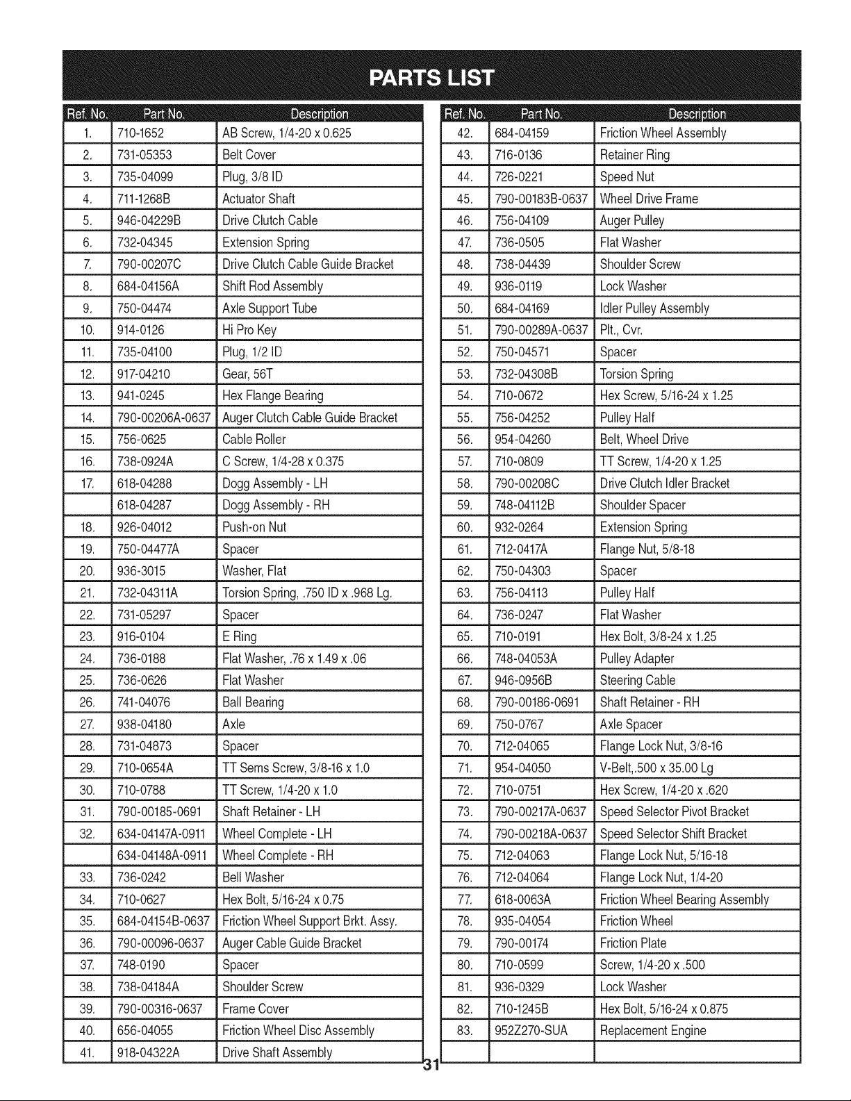
D_ i B O ¸
710-1652 AB Screw,1/4-20x 0.625
2. 731-05353 BeltCover
3. 735-04099 Plug,3/8 ID
4. 711-1268B ActuatorShaft
5. 946-04229B DriveClutchCable
6. 732-04345 ExtensionSpring
7. 790-002070 DriveClutchCableGuideBracket
8. 684-04156A ShiftRodAssembly
9. 750-04474 AxleSupportTube
10. 914-0126 Hi ProKey
11. 735-04100 Plug,1/2 ID
12. 917-04210 Gear,56T
13. 941-0245 HexFlangeBearing
14. 790-00206A-0637 AugerClutchCableGuideBracket
15. 756-0625 CableRoller
16. 738-0924A C Screw,1/4-28x 0.375
17. 618-04288 DoggAssembly-LH
618-04287 DoggAssembly- RH
18. 926-04012 Push-onNut
19. 750-04477A Spacer
20. 936-3015 Washer,Fiat
21. 732-04311A TorsionSpring,.750ID x .968 Lg.
22. 731-05297 Spacer
23. 916-0104 E Ring
24. 736-0188 FiatWasher,.76x 1.49x .06
25. 736-0626 FiatWasher
26. 741-04076 BallBearing
27. 938-04180 Axle
28. L731-04873 Spacer
29. 710-0654A
30. 710-0788
31. 790-00185-0691
32. 634-04147A-0911
634-04148A-0911
TTSeresScrew,3/8-16x 1.0
TTScrew,1/4-20x 1.0
ShaftRetainer- LH
WheelComplete-LH
WheelComplete-RH
33. 736-0242
34. 710-0627
35. 684-04154B-0637
36. 790-00096-0637
3_ 748-0190
38. 738-04184A
39. 790-00316-0637
40. 656-04055
41. 918-04322A
BellWasher
HexBolt,5/16-24x 0.75
FrictionWheelSupportBrkt.Assy.
AugerCableGuideBracket
Spacer
ShoulderScrew
FrameCover
FrictionWheelDiscAssembly
DriveShaftAssembly
31
m _ O
684-04159 FrictionWheelAssembly
43. 716-0136 RetainerRing
44. 726-0221 SpeedNut
45. 790-00183B-0637 WheelDrive Frame
46. 756-04109 AugerPulley
47. 736-0505 FiatWasher
48. 738-04439 ShoulderScrew
49. 936-0119 LockWasher
50. 684-04169 IdlerPulleyAssembly
51. 790-00289A-0637 Pit.,Cvr.
52. 750-04571 Spacer
53. 732-04308B TorsionSpring
54. 710-0672 HexScrew,5/16-24x 1.25
55. 756-04252 PulleyHalf
56. 954-04260 Belt,WheelDrive
57. 710-0809 TT Screw,1/4-20x 1.25
58. 790-002080 DriveClutchIdlerBracket
59. 748-04112B ShoulderSpacer
60. 932-0264 ExtensionSpring
61. 712-0417A FlangeNut,5/8-18
62. 750-04303 Spacer
63. 756-04113 PulleyHalf
64. 736-0247 FiatWasher
65. 710-0191 HexBolt,3/8-24x 1.25
66. 748-04053A PulleyAdapter
67. 946-0956B SteeringCable
68. 790-00186-0691 Shaft Retainer- RH
69. 750-0767 Axle Spacer
70. 712-04065 FlangeLock Nut,3/8-16
71. 954-04050 V-Belt,.500x 35.00 Lg
72. 710-0751 HexScrew,1/4-20x .620
73. 790-00217A-0637 SpeedSelectorPivotBracket
74. 790-00218A-0637 SpeedSelectorShiftBracket
75. 712-04063 FlangeLock Nut,5/16-18
76. 712-04064 FlangeLock Nut, 1/4-20
77. 618-0063A FrictionWheelBearingAssembly
78. 935-04054 FrictionWheel
79. 790-00174 FrictionPlate
80. 710-0599 Screw,1/4-20x .500
81. 936-0329 LockWasher
82. 710-1245B HexBolt,5/16-24x 0.875
83. 952Z270-SUA ReplacementEngine
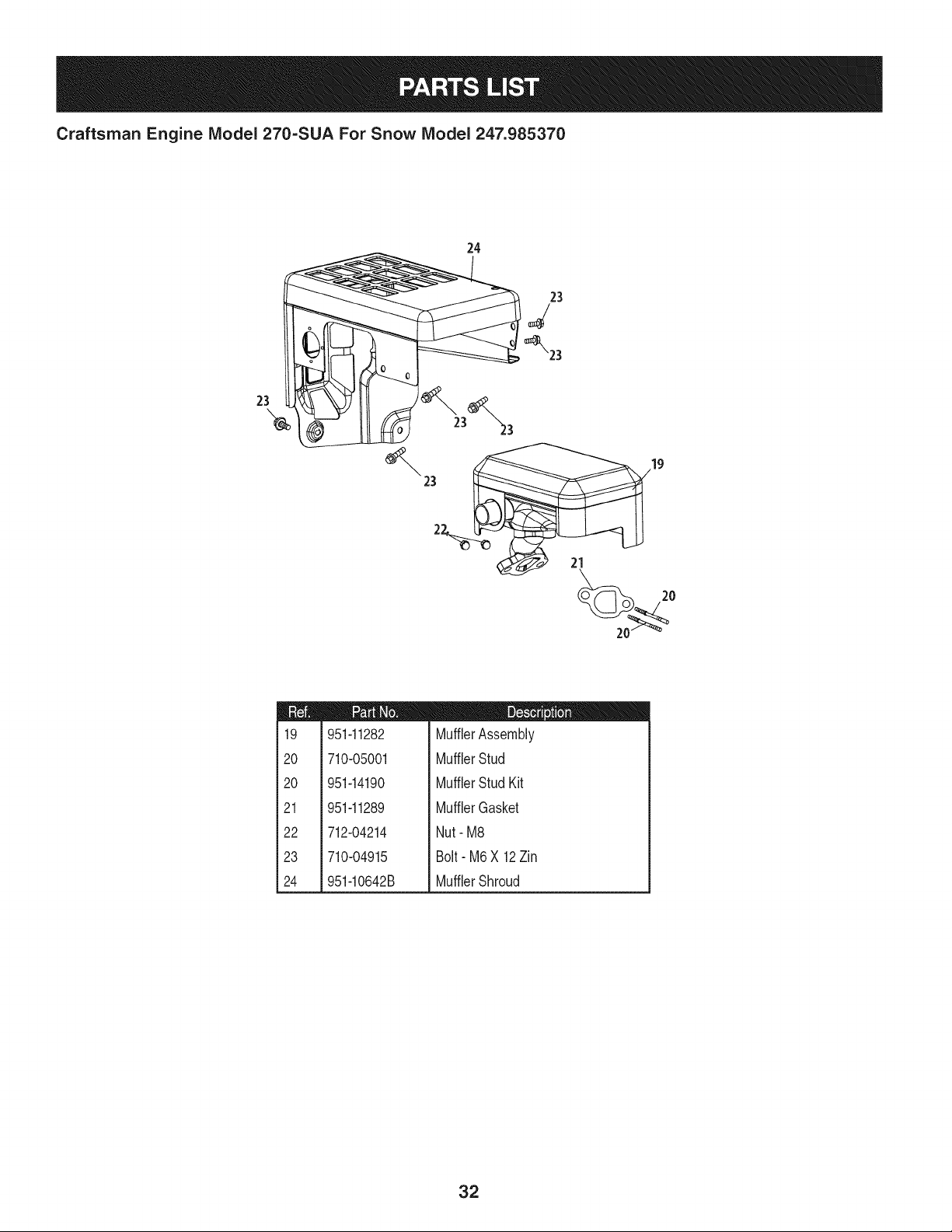
Craftsman Engine Model 270=SUA For Snow Model 247.985370
24
23
23
2
21
m
l
i
i19
!
i
120
i
i
i
i20
!
!
i
121
i
i
122
i
i
i
i23
!
i
i
124
i
951-11282
710-05001
951-14190
951-11289
712-04214
710-04915
951-10642B
m = 0 O
MufflerAssembly
MufflerStud
MufflerStud Kit
MufflerGasket
Nut- M8
Bolt- M6X 12Zin
MufflerShroud
32
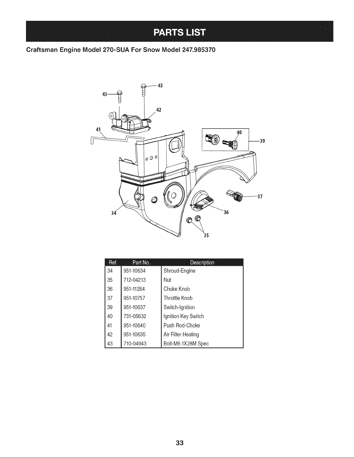
Craftsman Engine Model 270=SUA For Snow Model 247.985370
41 _42
°0
37
35
m
34
35
36
37
39
4O
41
42
43
951-10634
712-04213
951-11284
951-10757
951-10637
731-05632
951-10640
951-10635
710-04943
D = O O
Shroud-Engine
Nut
ChokeKnob
ThrottleKnob
Switch-Ignition
IgnitionKeySwitch
PushRod-Choke
Air Filter Heating
Bolt-M61X28MSpec
33
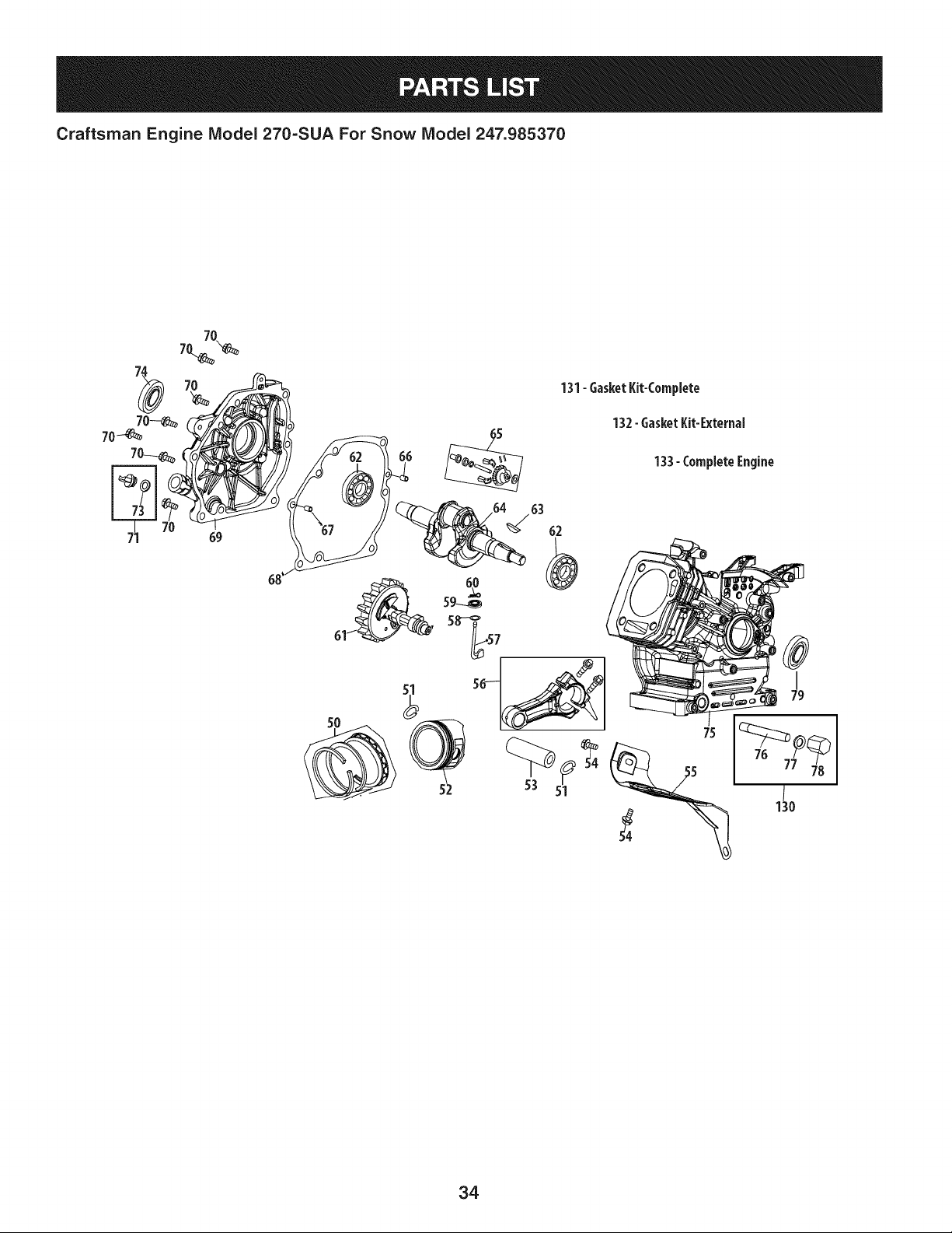
Craftsman Engine IViodel 270=SUA For Snow IViodel 247.985370
131-6asketKit-Complete
132-6asketKit-External
133- CompleteEngine
34
Craftsman Engine IViodel 270=SUA For Snow IViodel 247.985370
m
5O
51
52
53
54
55
56
57
58
59
6O
61
62
63
64
65
66
67
68
69
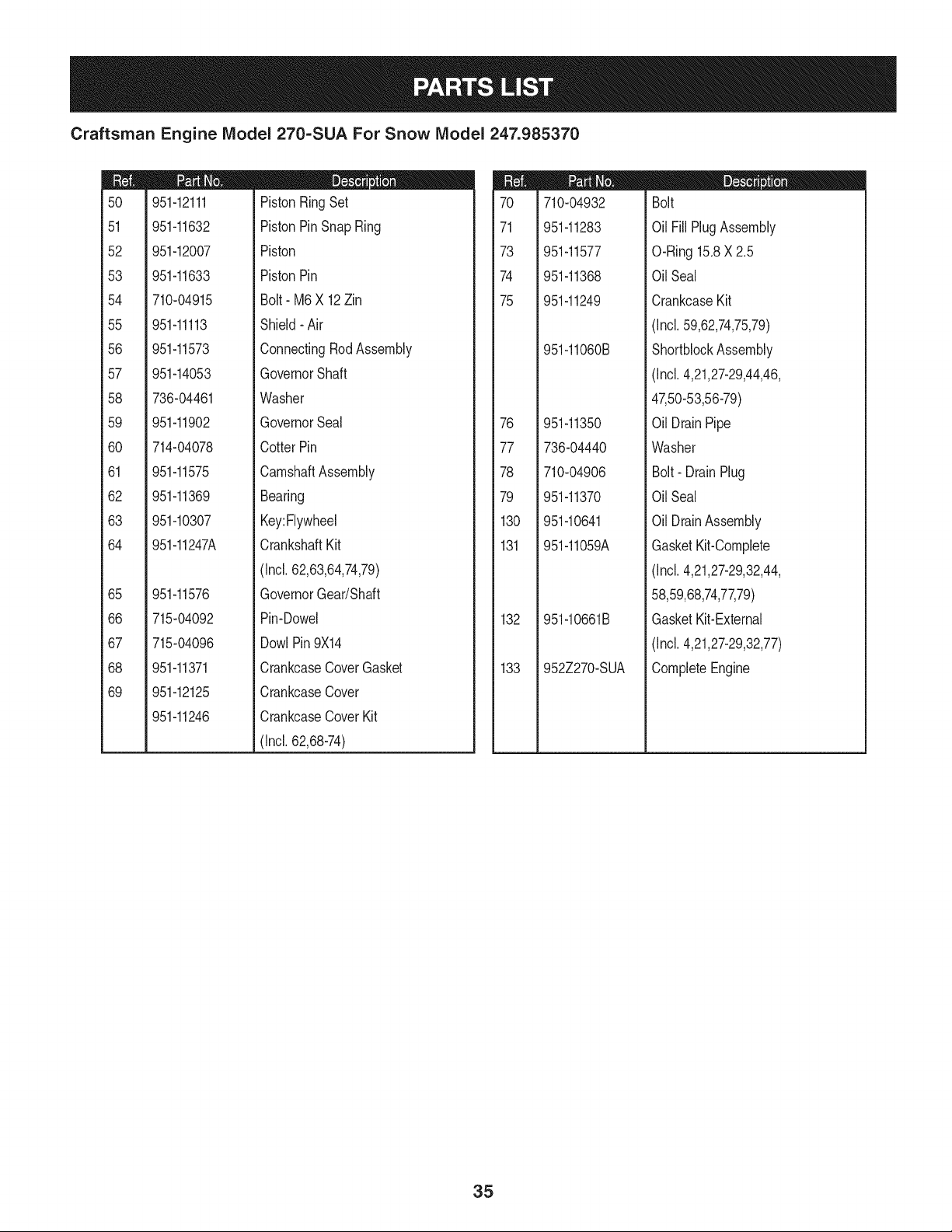
951-12111
951-11632
951-12007
951-11633
710-04915
951-11113
951-11573
951-14053
736-04461
951-11902
714-04078
951-11575
951-11369
951-10307
951-11247A
951-11576
715-04092
715-04096
951-11371
951-12125
951-11246
D = O
PistonRingSet
PistonPinSnap Ring
Piston
PistonPin
Bolt- M6X 12Zin
Shield- Air
ConnectingRodAssembly
GovernorShaft
Washer
GovernorSeal
CotterPin
CamshaftAssembly
Bearing
Key:Flywheel
CrankshaftKit
(Incl.62,63,64,74,79)
GovernorGear/Shaft
Pin-Dowel
DowlPin9X14
CrankcaseCoverGasket
CrankcaseCover
CrankcaseCoverKit
(Incl.62,68-74)
m
7O
71
73
74
75
76
77
78
79
130
131
132
133
710-04932
951-11283
951-11577
951-11368
951-11249
951-11060B
951-11350
736-04440
710-04906
951-11370
951-10641
951-11059A
951-10661B
952Z270-SUA
D = O O
Bolt
Oil FillPlugAssembly
O-Ring15.8X 2.5
OilSeal
CrankcaseKit
(Incl.59,62,74,75,79)
ShortblockAssembly
(Incl.4,21,27-29,44,46,
47,50-53,56-79)
Oil DrainPipe
Washer
Bolt- DrainPlug
OilSeal
Oil DrainAssembly
GasketKit-Complete
(Incl.4,21,27-29,32,44,
58,59,68,74,77,79)
GasketKit-External
(Incl.4,21,27-29,32,77)
CompleteEngine
35
Craftsman Engine Model 270-SUA For Snow Model 247.985370
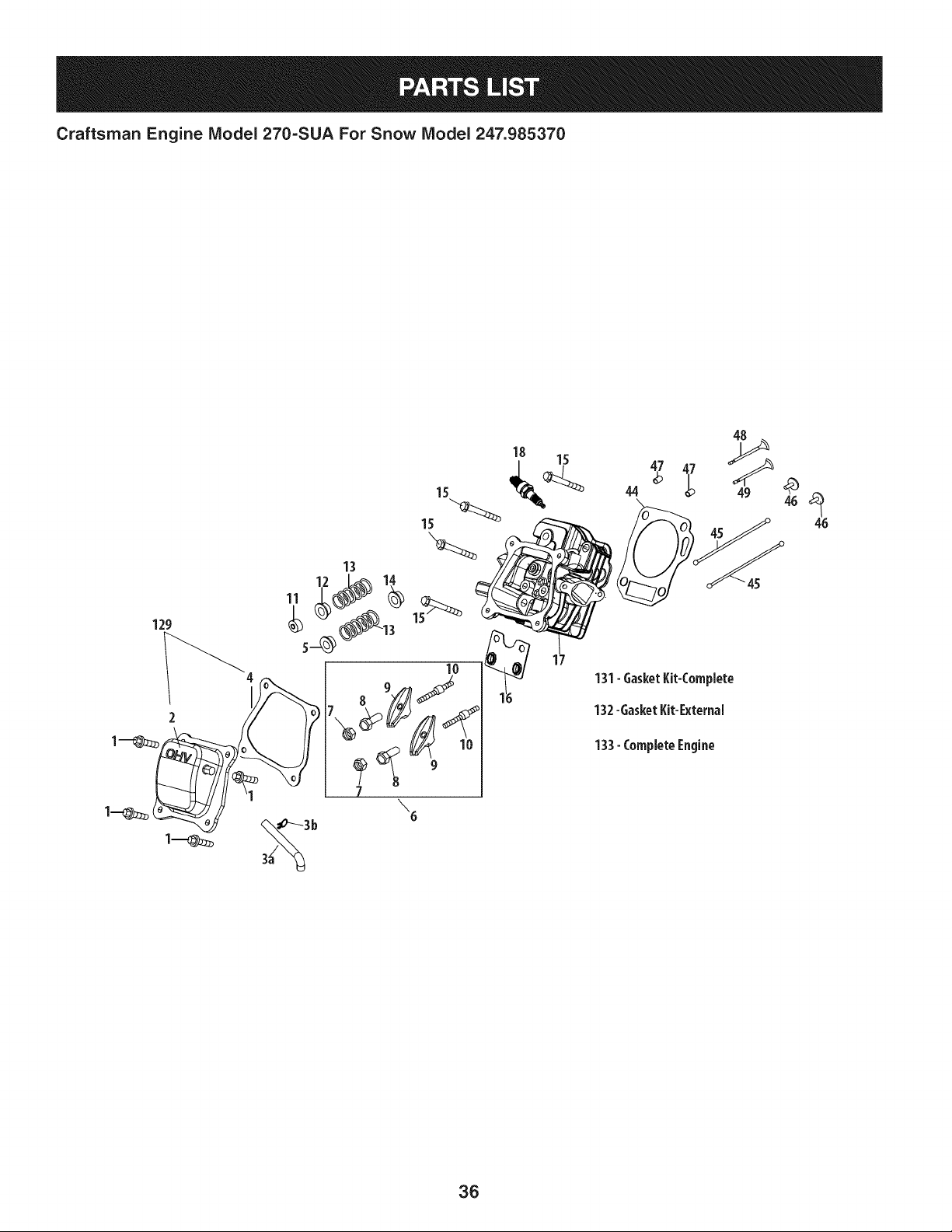
129
15
13
18
17
44 _p 49 46 _46
_ U" -"45
131-GasketKit-Complete
132-GasketKit-External
133-CompleteEngine
36
Craftsman Engine IViodel 270=SUA For Snow IViodel 247.985370
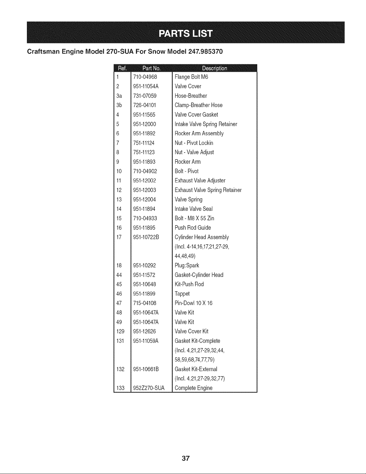
m
1
2
3a
3b
4
5
6
7
8
9
10
11
12
13
14
15
16
17
18
44
45
46
47
48
49
129
131
132
133
710-04968
951-11054A
731-07059
726-04101
951-11565
951-12000
951-11892
751-11124
751-11123
951-11893
710-04902
951-12002
951-12003
951-12004
951-11894
710-04933
951-11895
951-10722B
951-10292
951-11572
951-10648
951-11899
715-04108
951-10647A
951-10647A
951-12626
951-11059A
951-10661B
952Z270-SUA
D = O O
FlangeBoltM6
ValveCover
Hose-Breather
Clamp-BreatherHose
ValveCoverGasket
IntakeValveSpring Retainer
RockerArmAssembly
Nut- PivotLockin
Nut- ValveAdjust
RockerArm
Bolt- Pivot
ExhaustValveAdjuster
ExhaustValveSpringRetainer
ValveSpring
IntakeValveSeal
Bolt- M8X 55Zin
PushRodGuide
CylinderHeadAssembly
(Incl.4-14,16,17,21,27-29,
44,48,49)
Plug:Spark
Gasket-CylinderHead
Kit-PushRod
Tappet
Pin-Dow110X 16
ValveKit
ValveKit
ValveCover Kit
GasketKit-Complete
(Incl.4,21,27-29,32,44,
58,59,68,74,77,79)
GasketKit-External
(Incl.4,21,27-29,32,77)
CompleteEngine
37
Craftsman Engine IViodel 270=SUA For Snow IViodel 247.985370
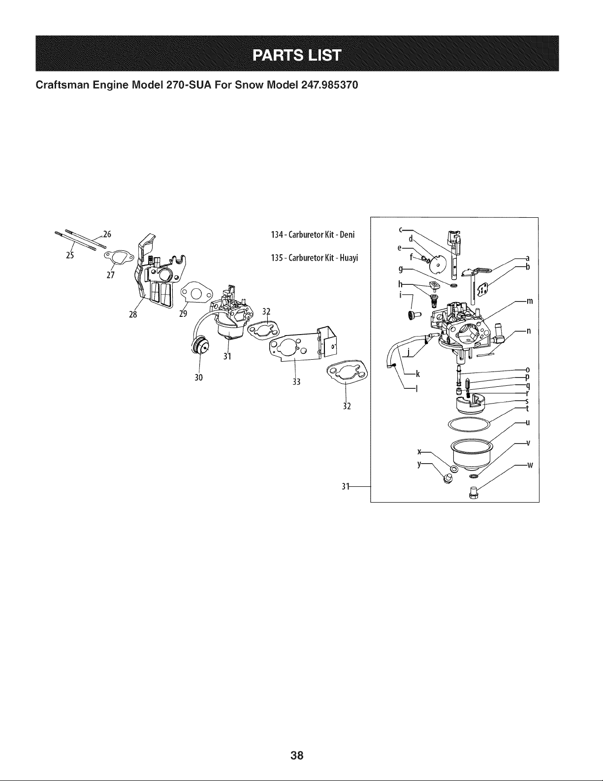
27
134-CarburetorKit- Deni
135- CarburetorKit- Huayi
w
38
Craftsman Engine IViodel 270=SUA For Snow IViodel 247.985370
m
25
26
27
28
29
30
30
31
31
32
33
134
135
a
b
C
d
e
f
g
h
I
J
k
I
I1q
n
o
P
q
r
s
t
U
V
W
X
Y
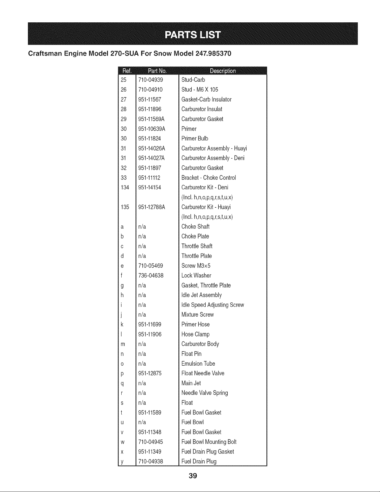
710-04939
710-04910
951-11567
951-11896
951-11569A
951-10639A
951-11824
951-14026A
951-14027A
951-11897
951-11112
951-14154
951-12788A
n/a
n/a
n/a
n/a
710-05469
736-04638
n/a
n/a
n/a
n/a
951-11699
951-11906
n/a
n/a
n/a
951-12875
n/a
n/a
n/a
951-11589
n/a
951-11348
710-04945
951-11349
710-04938
D = W O
Stud-Carb
Stud- M6X 105
Gasket-CarbInsulator
CarburetorInsuiat
CarburetorGasket
Primer
PrimerBulb
CarburetorAssembly- Huayi
CarburetorAssembly- Deni
CarburetorGasket
Bracket- ChokeControl
CarburetorKit- Deni
(Incl.h,n,o,p,q,r,s,t,u,x)
CarburetorKit- Huayi
(Incl.h,n,o,p,q,r,s,t,u,x)
ChokeShaft
ChokePlate
ThrottleShaft
ThrottlePlate
ScrewM3x5
LockWasher
Gasket,ThrottlePlate
IdleJet Assembly
Idle SpeedAdjustingScrew
MixtureScrew
PrimerHose
HoseClamp
CarburetorBody
FloatPin
EmulsionTube
FloatNeedleValve
MainJet
NeedleValveSpring
Float
FuelBowlGasket
FuelBowl
FuelBowlGasket
FuelBowlMountingBolt
FuelDrainPlugGasket
FuelDrainPlug
39
Craftsman Engine IViodel 270-SUA For Snow IViodel 247.985370
82
84
85
m
8O
81
82
83
84
85
86
87
88
90
91
92
93
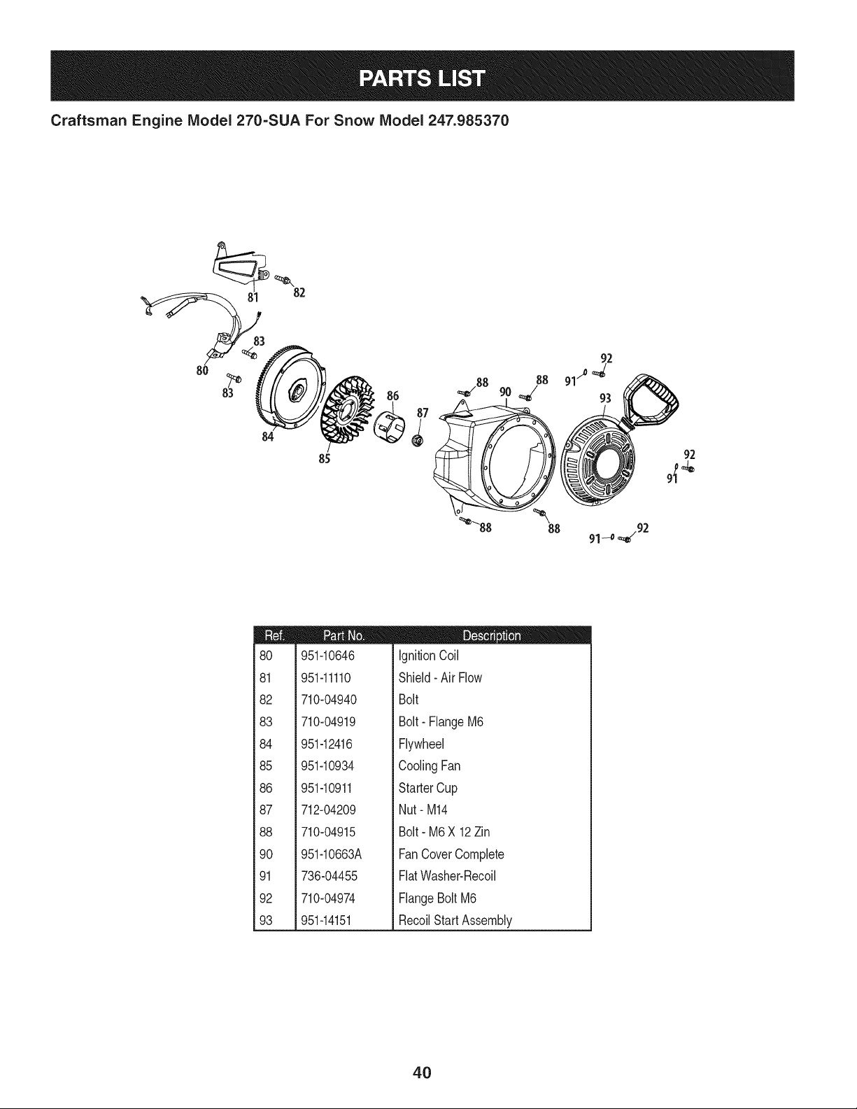
951-10646
951-11110
710-04940
710-04919
951-12416
951-10934
951-10911
712-04209
710-04915
951-10663A
736-04455
710-04974
951-14151
D = O O
IgnitionCoil
Shield- Air Flow
Bolt
Bolt- FlangeM6
Flywheel
CoolingFan
StarterCup
Nut- M14
Bolt- M6X 12Zin
FanCoverComplete
FlatWasher-Recoil
FlangeBolt M6
RecoilStartAssembly
4O
Craftsman Engine IViodel 270=SUA For Snow IViodel 247.985370
,114
115
95 102 _---115
9s- 97 9s
105
94
105
104
m
94
95
96
97
98
99
101
102
103
104
105
106
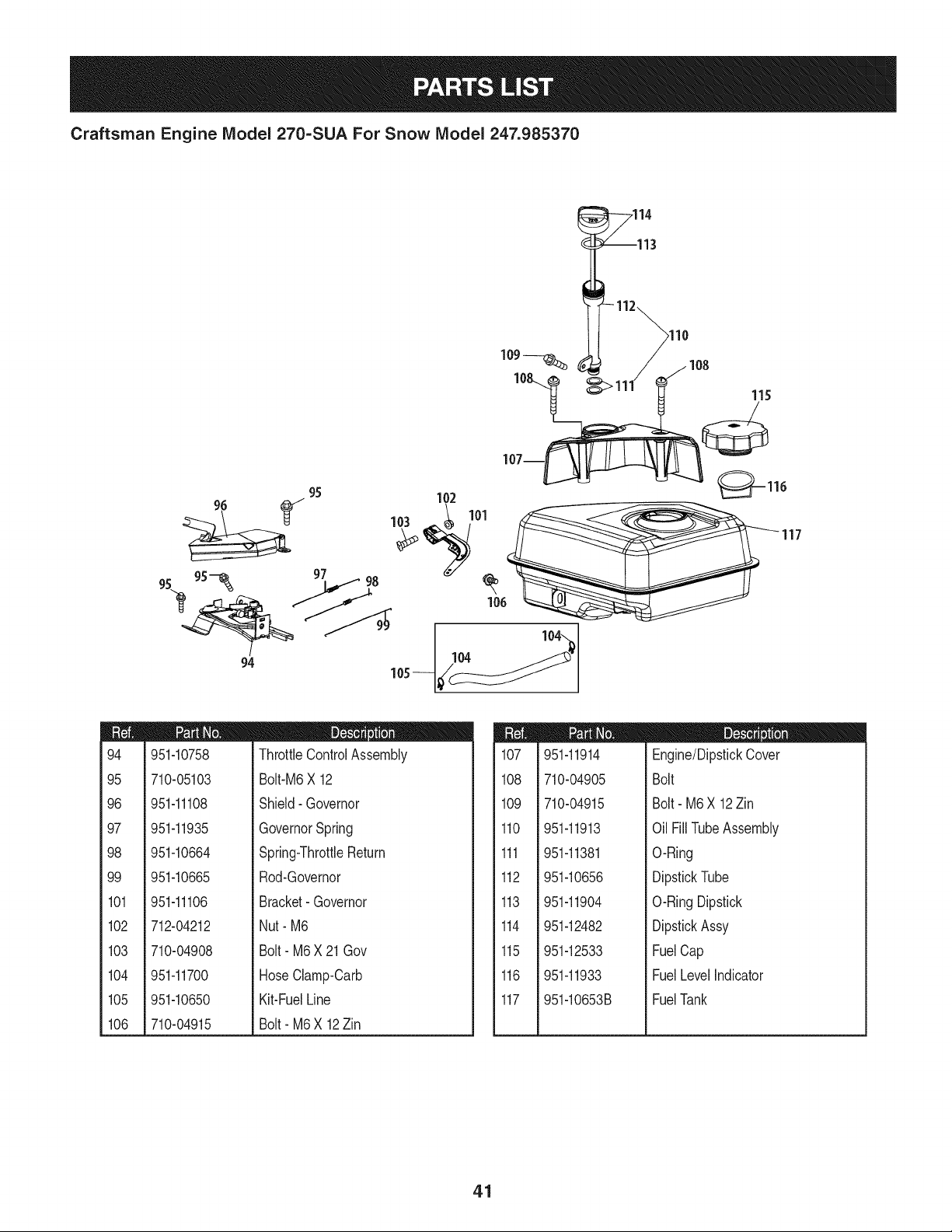
951-10758
710-05103
951-11108
951-11935
951-10664
951-10665
951-11106
712-04212
710-04908
951-11700
951-10650
710-04915
D = O 0
ThrottleControlAssembly
Bolt-M6X 12
Shield- Governor
GovernorSpring
Spring-ThrottleReturn
Rod-Governor
Bracket-Governor
Nut- M6
Bolt- M6X 21 Gov
HoseClamp-Oarb
Kit-FuelLine
Bolt- M6X 12Zin
m
107
108
109
110
111
112
113
114
115
116
117
951-11914
710-04905
710-04915
951-11913
951-11381
951-10656
951-11904
951-12482
951-12533
951-11933
951-10653B
D = O 0
Engine/DipstickCover
Bolt
Bolt- M6X 12Zin
Oil FillTubeAssembly
O-Ring
DipstickTube
O-RingDipstick
DipstickAssy
FuelCap
FuelLevelIndicator
FuelTank
41
Craftsman Engine IViodel 270=SUA For Snow IViodel 247.985370
23
m
i
1118
1
1
1
i119
!
i
i 120
1
1
1
1121
1
1
1
i 122
!
i
i 123
1
1
1
i 124
!
!
i
i 125
1
1
i 126
1
1
1
i 127
!
i
1
i 128
1
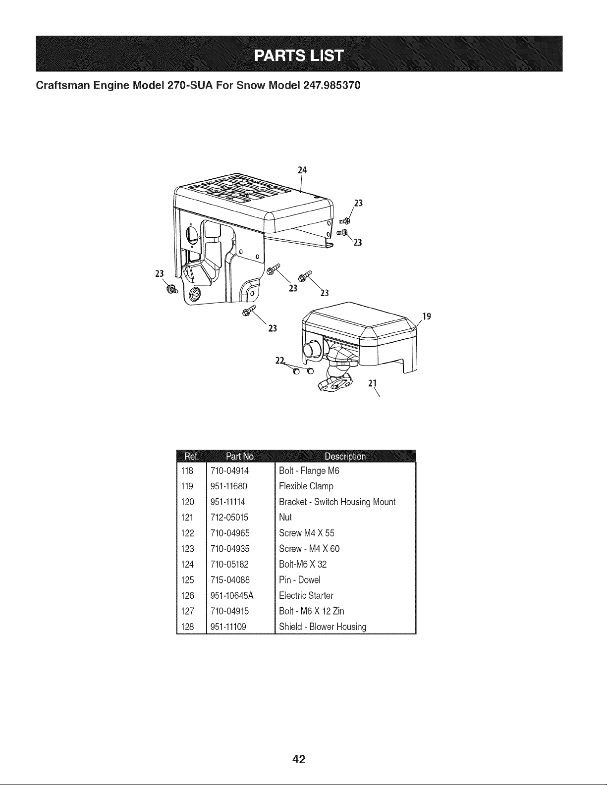
710-04914
951-11680
951-11114
712-05015
710-04965
710-04935
710-05182
715-04088
951-10645A
710-04915
951-11109
D = O !
Bolt- FlangeM6
FlexibleClamp
Bracket- SwitchHousingMount
Nut
ScrewM4X 55
Screw- M4X 60
Bolt-M6X 32
Pin- Dowel
ElectricStarter
Bolt- M6 X 12Zin
Shield- BlowerHousing
42
Craftsman Snow Thrower Model 247.985370
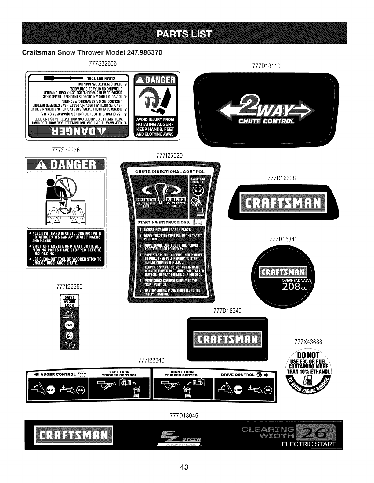
777S32636
777D18110
-- " _ 1001 ZO0-NV=130 •
7VflNY_ S,EIOIVEI3dO QV3EI "g
"S33WUflS 13AV_9 NO9NIlVU3d0
N3HM N011flV3VUIX3 3Sn "8_30NV1S181¥ 399VH3SI0
133UIQ U3A3N 'S31UnFNI $103r80 NMOUHL QIOAV 01 "_
"3NIHOV_ 9NIOIAU3S _0 8NI09013Nn
3U0438 03dd01S 3AVH SIUV,4 8NIA0_ ]lV llZNfl 831QNVH
ONIH38 NIV_3H 0NV '3NIgN3 d01S 'SH3A3] HOlfl10 30VgN_810 "_
"31fill0 39UVHOSIQ 9013Nfl 01 1001 lf10"NV313 3Sfl "g
"133JONV SQNVH31Vlfld_V NV3 E39flV E0 _3113d_1 HIlM
10PIN00 "U30flVQNV U3113J_I 9NIIV10U WOUJ IVMV d33_ "L
777S32236
777125020
STARTING iNSTRUCTiONS:
777D16338
777D16341
777122363
777D16340
777X43688
777122340
CONTAININGMORE
o
THAN10 '/oETHANOL
777D18045
43
MTD CONSUMER GROUP INC (MTD), the California Air Resources Board (CARB)
and the United States Environment Protection Agency (U. S. EPA)
Emission Control System Warranty Statement
(Owner's Defect Warranty Rights and Obligations)
EMISSIONCONTROLSYSTEMCOVERAGEIS APPLICABLETOCERTIFIEDENGINESPURCHASEDINCALIFORNIAIN 2005 ANDTHERE-
AFTER,WHICHARE USEDIN CALIFORNIA,ANDTO CERTIFIEDMODELYEAR2005ANDLATERENGINESWHICHARE PURCHASEDAND
USEDELSEWHEREIN THE UNITEDSTATES.
Californiaandelsewherein the UnitedStatesEmissionControlDefectsWarrantyCoverage
The CaliforniaAir ResourcesBoard(CARB),U. S. EPAand MTDare pleasedto explaintheemissionscontrolsystemwarrantyonyour modelyear
2006and latersmalloff-roadengine.In California,new smalloff-roadenginesmustbe designed,builtand equippedto meet theStatesanti-smog
standards.Elsewhereinthe UnitedStates,newnon-road,spark-ignitionenginescertifiedfor model2005and later,mustmeetsimilarstandardsset
forthby the U.S. EPA.MTDmustwarrantythe emissioncontrolsystemonyourenginefor the periodof timelistedbelow,providedtherehasbeen
noabuse,neglector impropermaintenanceof your smalloff-roadengine.
Youremissioncontrolsystemmayincludepartssuch as the carburetor,fuel-injectionsystem,the ignitionsystem,and catalyticconverter,fueltanks,
fuel lines,fuel caps,valves,canisters,filters,vaporhoses,clamps,connectors,andotherassociatedemission-relatedcomponents.
Wherea warrantableconditionexists,MTDwill repairyoursmalloff-roadengineat nocost to yourincludingdiagnosis,partsand labor.
MANUFACTURER'S WARRANTY COVERAGE:
Thisemissionscontrolsystemis warrantedfor two years.If anyemission-relatedpart onyourengine is defective,the part will berepairedor
replacedby MTD.
OWNER'S WARRANTY RESPONSIBILITIES:
As the smalloff-roadengineowner,youare responsibleforthe performanceof the requiredmaintenancelisted inyour Owner'sManual.MTD
recommendsthatyou retainall yourreceiptscoveringmaintenanceson yoursmalloff-roadengine,but MTDcan not denywarrantysolelyfor the
lackof receiptsor foryour failureto ensurethe performanceto all scheduledmaintenance.
As the smalloff-roadengineowner,youshouldhoweverbeawarethat MTDmaydenyyour warrantycoverageif yoursmalloff-roadengineorpart
hasfaileddue toabuse, neglect,impropermaintenanceor unapprovedmodifications.
Youare responsiblefor presentingyour smalloff-roadengineto an AuthorizedMTDServiceDealeras soonas a problemexists.Thewarranted
repairsshouldbe completedin a reasonableamountof time,notto exceed30 days.
Ifyou haveanyquestionsregardingyourwarrantyrightsand responsibilities,you shouldcontacta MTDServiceRepresentativeat 1-800-800-7310
andaddressis MTDCONSUMERGROUP,RO.Box361131,ClevelandOH,44136-0019.
DEFECTS WARRANTY REQUIREMENTS FOR 1995 AND LATER SMALL OFF-ROAD ENGINES:
Thissectionappliesto 1995andlater smalloff-roadengines.The warrantyperiodbeginson the datethe engineor equipmentis deliveredto an
ultimatepurchaser.
(a) GeneralEmissionsWarrantyCoverage_
MTDmustwarrantto the ultimatepurchaserand eachsubsequentpurchaserthatthe engineis:
(1)Designed,built,andequippedsoas to conformwith all applicableregulationsadoptedby the Air ResourcesBoardpursuantto itsauthorityin
Chapters1 and2,Part5, Division26 of the Healthand SafetyCode;and
(2) Freefromdefectsin materialsand workmanshipthat causethe failureof a warrantedpart to be identicalin all materialrespectsto the partas
describedin theengine manufacturer'sapplicationfor certificationfora periodof twoyears.
.(b)The warrantyonemissions-relatedpartswill be interpretedas follows:
(1)Anywarrantedpart thatis not scheduledfor replacementas requiredmaintenanceinthe writteninstructionsrequiredby Subsection(c)
mustbewarrantedfor the warrantyperioddefinedin Subsection(a)(2). If any such partfails duringthe periodof warrantycoverage,it mustbe
repairedor replacedby MTDaccordingto Subsection(4) below.Anysuch part repairedor replacedunderthewarrantymustbewarrantedfor
the remainingwarrantyperiod.
(2)Any warrantedpartthat is scheduledonlyfor regularinspectioninthe writteninstructionsrequiredby Subsection(c) must be warrantedfor
thewarrantyperioddefinedin Subsection(a)(2).A statementin such writteninstructionsto the effectof "repairor replaceas necessary"will
not reducethe periodof warrantycoverage.Anysuchpart repairedor replacedunderwarrantymustbe warrantedforthe remainingwarranty
period.
(3) Anywarrantedpartthat whichis scheduledfor replacementas requiredmaintenancein the writteninstructionsrequiredby Subsection(c)
mustbewarrantedfor the periodof timeprior to the first scheduledreplacementpointforthat part. If the part fails priorto thefirst scheduled
replacement,the part mustbe repairedor replacedby MTDaccordingto Subsection(4) below.Any suchpart repairedor replacedunder
warrantymustbe warrantedfor the remainderof the periodpriorto the first scheduledreplacementpointfor the part.
(4) Repairor replacementof any warrantedpartunderthewarrantyprovisionsof this article mustbe performedat nochargeto the ownerat a
warrantystation.
(5) Notwithstandingthe provisionsof Subsection(4) above,warrantyservicesor repairsmustbe providedat all MTDdistributioncentersthat
arefranchisedto servicethe subjectengines.
(6)Theownermustnotbechargedfordiagnosticlaborthatleadstothedeterminationthatawarrantedpartisinfactdefective,providedthat
suchdiagnosticworkisperformedatawarrantystation.
(7)Theenginemanufacturerisliablefordamagestootherenginecomponentsproximatelycausedbyafailureunderwarrantyofanywarranted
part.
(8)Throughouttheengine'swarrantyperioddefinedinSubsection(a)(2),MTDwillmaintainasupplyofwarrantedpartssufficienttomeetthe
expecteddemandforsuchparts.
(9)Anyreplacementpartmaybeusedintheperformanceofanywarrantymaintenanceorrepairsandmustbeprovidedwithoutchargetothe
owner.SuchusewillnotreducethewarrantyobligationsofMTD.
(10)Add-onormodifiedpartsthatarenotexemptedbytheAirResourcesBoardmaynotbeused.Theuseofanynon-exemptedadd-onor
modifiedpartsshallbegroundsfordisallowingawarrantyclaimmadeinaccordancewiththisarticle.Theenginemanufacturershallnotbe
liableunderthisarticletowarrantfailuresofwarrantedpartscausedbytheuseofnon-exemptedadd-onormodifiedpart.
(c) MTDwill includea copyof the followingemissionwarrantypartslistwith each newengine,usingthoseportionsof the listapplicableto the
e__&gine.
(1)FuelMeteringSystem
• Coldstart enrichmentsystem(soft choke)
,,Carburetorandinternalparts
• Fuel Pump
• FuelTank
(2)Air InductionSystem
• Aircleaner
• Intakemanifold
(3) IgnitionSystem
• Sparkplug(s)
• MagnetoIgnitionSystem
(4)ExhaustSystem
Catalyticconverter
• SAI (Reedvalve)
(5) MiscellaneousItemsUsedin AboveSystem
Vacuum,temperature, position,timesensitivevalvesand switches
Connectorsandassemblies
(6) Evaporativecontrol
• Fuel Hosecertifiedfor ARBevaporativeemissionof 2006.
• Fuel HoseClamps
Tetheredfuel cap
Carboncanister
• Vaporlines
GD0C-100174Rev.B
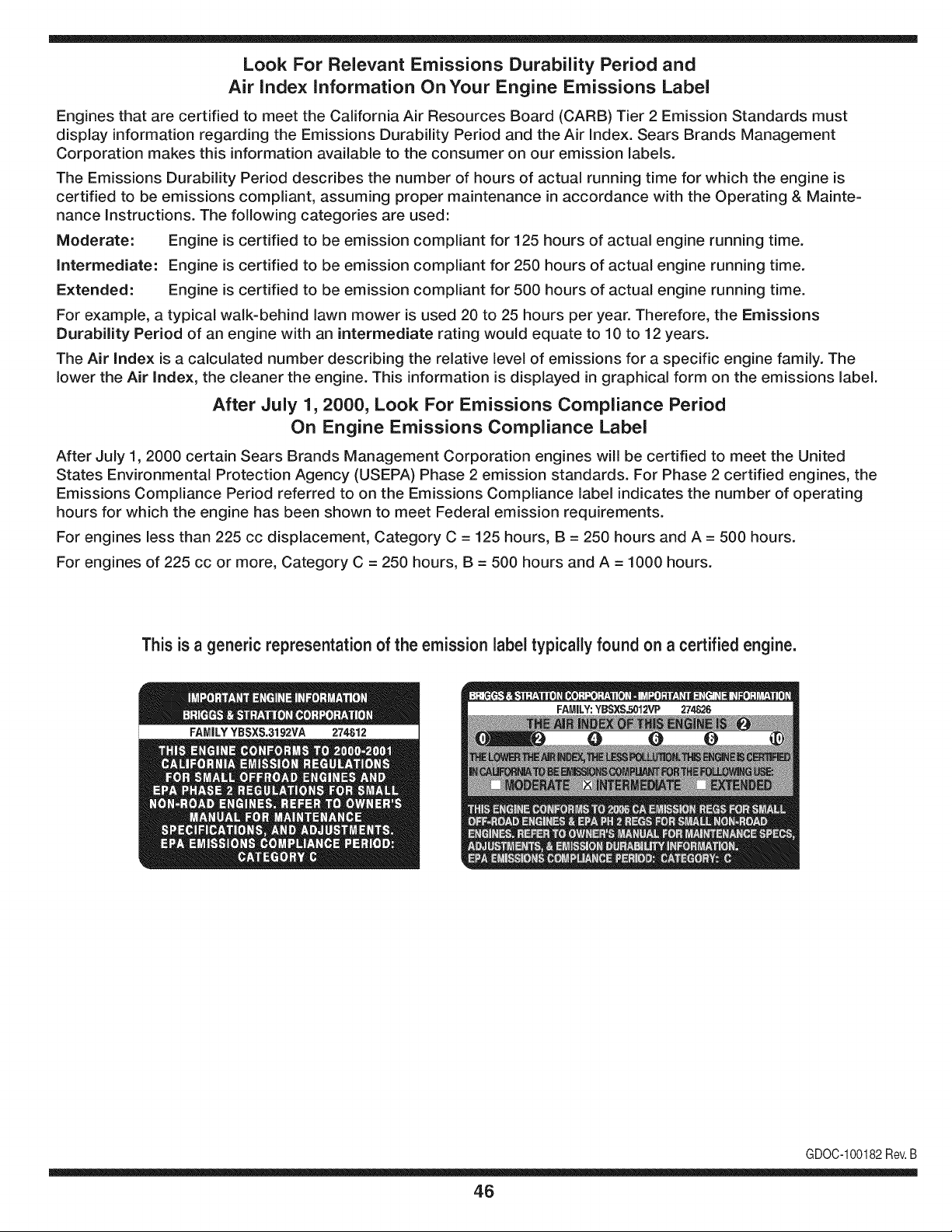
Look For Relevant Emissions Durability Period and
Air index information On Your Engine Emissions Label
Engines that are certified to meet the California Air Resources Board (CARB) Tier 2 Emission Standards must
display information regarding the Emissions Durability Period and the Air Index. Sears Brands Management
Corporation makes this information available to the consumer on our emission labels.
The Emissions Durability Period describes the number of hours of actual running time for which the engine is
certified to be emissions compliant, assuming proper maintenance in accordance with the Operating & Mainte-
nance Instructions. The following categories are used:
Moderate: Engine is certified to be emission compliant for 125 hours of actual engine running time.
Intermediate: Engine is certified to be emission compliant for 250 hours of actual engine running time.
Extended: Engine is certified to be emission compliant for 500 hours of actual engine running time.
For example, a typical walk-behind lawn mower is used 20 to 25 hours per year. Therefore, the Emissions
Durability Period of an engine with an intermediate rating would equate to 10 to 12 years.
The Air index is a calculated number describing the relative level of emissions for a specific engine family. The
lower the Air Index, the cleaner the engine. This information is displayed in graphical form on the emissions label.
After July 1,2000, Look For Emissions Compliance Period
On Engine Emissions Compliance Label
After July 1, 2000 certain Sears Brands Management Corporation engines will be certified to meet the United
States Environmental Protection Agency (USEPA) Phase 2 emission standards. For Phase 2 certified engines, the
Emissions Compliance Period referred to on the Emissions Compliance label indicates the number of operating
hours for which the engine has been shown to meet Federal emission requirements.
For engines less than 225 cc displacement, Category C = 125 hours, B = 250 hours and A = 500 hours.
For engines of 225 cc or more, Category C = 250 hours, B = 500 hours and A = 1000 hours.
This is a generic representation of the emission label typically found on a certified engine.
FAMILYYBSXS.3192VA 274812
GDOC-100182Rev.B
46
Congratulations on making a smart purchase. Your new Craftsman® product is designed and
manufactured for years of dependable operation. But like all products, it may require repair
from time to time. That's when having a Repair Protection Agreement can save you money and
aggravation.
Here's what the Repair Protection Agreement* includes:
[] Expert service by our 10,000 professional repair specialists
[] Unlimited service and no charge for parts and labor on all covered repairs
[] Product replacement up to $1500 if your covered product can't be fixed
[] Discount of 25% from regular price of service and related installed parts not covered by the
agreement; also, 25% off regular price of preventive maintenance check
[] Fast help by phone - we call it Rapid Resolution - phone support from a Sears representative.
Think of us as a "talking owner's manual."
Once you purchase the Repair Protection Agreement, a simple phone call is all that it takes for you
to schedule service. You can call anytime day or night, or schedule a service appointment online.
The Repair Protection Agreement is a risk-free purchase. If you cancel for any reason during the
product warranty period, we will provide a full refund. Or, a prorated refund anytime after the
product warranty period expires. Purchase your Repair Protection Agreement today!
Some limitations and exclusions apply. For prices and additional information in the U.S.A.
call 1=800=827=6655.
*Coverage in Canada varies on some items. For full details call Sears Canada at 1=800=361=
6665.
Sears Installation Service
For Sears professional installation of home appliances, garage door openers, water heaters, and
other major home items, in the U.S.A. or Canada call 1=800=4=MY=HOME®.
47
Declaraci6n de garantia ............................ Pagina 48
Pr,_cticas operaci6n seguras ..................... Pagina 49
Montaje ...................................................... Pagina 53
Operaci6n .................................................. Pagina 59
Servicio y Mantenimiento .......................... Pagina 64
Almacenamiento fuera de temporada ....... Pagina 71
Soluci6n de problemas .............................. Pagina 72
Acuerdo de protecci6n para reparaciones .... Pagina 77
Lista de piezas ........................................... Pagina 26
NOmero de servicio ................................... Cubierta
posterior
GARANTiA COMPLETA CRAFTSMAN POR DOS ANOS
PORDOSANOSapartir dela fechade lacornpra,este productoest,. garantizadopor defectosen los rnaterialesy la rnanodeobra.
Los productosdefectuososser_.nreparadossin costoo reernplazadossin costosi la reparaci6nnoest,.disponiNe.
Paraobtener informaci6nsobre el alcancede la garantiay solieitar la reparaci6no el reemplazo,visiteel sitio Web:www.craftsman.com
Esta garantia cubre 0NICAMENTElos defectos en los rnatedales y en la mano de obra. Estagarantia NOcubre:
• Elernentosno renovablesque puedendesgastarsepor el uso normal,duranteel plazode la garantia,incluyendoentreotros,las barrenas,
las paletasdelas barrenas,los cortadoresde desplazarniento,laszapatasantideslizantes,la placade raspado,lospasadoresde cuchilla,
la bujia,el filtro de aire,las correasy el filtro deaceite.
• Serviciosde rnantenirnientoest_ndar,carnbiosde aceiteo afinaci6n.
• Carnbiode neurn_ticoso reparacionesporpinchadurascon objetosexternoscornoclavos,espinas,toconeso vidrios.
• Reernplazoo reparaci6nde neurn_ticoso ruedascornoresultadodel desgastenormal,un accidente,o funcionarniento
o rnantenirnientoincorrectos.
• Reparacionesrequeridascornoresultadodel uso inadecuadoporpartedel operador,incluyendoentreotrosel daSoocasionadopor objetos
queirnpactanla rnaquinay quetuercenel bastidor,el eje de labarrena,etc., odebidoa que el motorfueaceleradoen exceso.
• Reparacionesnecesariasdebidoa negligenciadeloperador,incluyendoentre otros,da_osrnec_nicoy el_ctricoocasionadopor
unalmacenarnientono apropiado,fallaporel uso deaceitede gradoy/o cantidadnoapropiadoso falla pornodar rnantenirniento
alequipode acuerdocon las instruccionescontenidasenel manualdel operador.
• Lirnpiezao reparacionesdel motor(sistemade combustible)debidasa combustibleque se deterrninaest&contarninadou oxidado(viejo).
Engeneral,el combustibledebeutilizarseen un periodono mayorde 30 dias a partirde su adquisici6n.
• Eldeterioroy desgastenormalde losacabadosexteriores,o reernplazode laetiquetadel producto.
Lapresentegarantiase anulasi se utilizaesteproductoalgunavezparaprestarservicioscornercialeso si se Ioalquilaa otra persona.
Estagarantialeotorgaderechoslegalesespecfficos,pero ustedpodriagozarde otrosderechosen raz6nde su lugarde residencia.
Sears Brands Management Corporation, Hoffman Estates, IL 60179
Tipode aceitedel motor:
Capacidaddeaceitedel motor:
Capacidaddecombustible:
Buj[as:
Separaci6nde lasbujias:
SAE 5W-30
20 onzas
2 cuartos
F6RTC (951-10292)
.020" a .030"
© Sears Brands,LLC
48
NSrnerode rnodelo ..........................................................
N_merode serie ..............................................................
Fechade eompra .............................................................
Registrearriba el nOrnerodel rnodelo,el nOrnerode seriey la fecha
decornpra
Lapresenciadeestesfrnboloindicaquesetratadeinstrucciones
irnportantesdeseguridadquesedebenrespetarparaevitar
ponerenpeligrosuseguridadpersonaly/omaterialyladeotras
personas.Leaysigatodaslasinstruccionesdeestemanualantes
deponerenfuncionarnientoestarn_.quina.Sinorespetaestas
instruccionespodrfaprovocarlesionespersonales.Cuandoveaeste
sfrnbolo,ipresteatenci6nalaadvertencia!
PROPOSICION 65 DE CALIFORNIA
Elescapedel motordeesteproducto,algunosde suscornponentes
y algunoscornponentesdelvehfculocontieneno liberansustancias
qufrnicasque el estadodeCaliforniaconsideraque puedenproducir
c_.ncer,defectosde nacirnientou otrosproblernasreproductivos.
Estarn_.quinarueconstruidapara seroperadade acuerdocon
las reglasde seguridadcontenidaseneste manual.AI igualque
concualquiertipo de equipornotorizado,un descuidoo errorpor
partedeloperadorpuedeproducirlesionesgraves.Estarn_.quina
es capazde arnputarrnanosy piesy de arrojarobjetoscon gran
fuerza.Deno respetarlas instruccionesde seguridadsiguientesse
puedenproducirlesionesgraveso la rnuerte.
Su responsabilidad--Restrinja el usode esta rn_.quina
rnotorizadaalas personasque lean,cornprendany respetenlas
advertenciase instruccionesqueaparecenen estemanualyen la
rn_.quina.
iGUARDEESTASINSTRUCCIONES!
CAPACITACI6N
• Lea,entienday curnplatodaslas instruccionesincluidasen
la rn_.quinay enlos rnanualesantesdernontarlay utiNzarla.
Guardeestemanualenun lugarseguroparaconsultasfuturasy
peri6dicas,asf cornopara solicitarrepuestos.
• Leael ManualdelOperadory sigatodas las advertenciase
instruccionesde seguridad.Elfracasode hacerasf puedecausar
la heridaseriaal operadory/o personaspresentes.
• Farniliarfcesecontodoslos controlesy con el usoadecuado
delos rnisrnos.Sepa c6rnodetenerlarn_.quinay desactivarlos
controlesr_.pidarnente.
• No perrnitanuncaque los ni_osrnenoresde 14a_osutilicen
estarn_.quina.Los ni_osde 14a_osen adelantedebenleery
entenderlas instruccionesde operaci6ny norrnasde seguridad
contenidasen este manual,yen la rn_.quinaydebenser entrena-
dosy supervisadosporun adulto.
• Nuncaperrnitaque los adultosoperenestarn_.quinasin recibir
antesla instrucci6napropiada.
• Losobjetosarrojadospor la rn_.quinapuedenproducirlesiones
graves.Planifiqueel patr6nen el queva air arrojandonievepara
evitarque la descargade materialse realicehacialos carninos,
los observadores,etc.
• Mantengaa losobservadores,ayudantes,rnascotasy ni_ospor
Io rnenosa 75piesde la rn_.quinarnientrasla rnisrnaest,.en
funcionarniento.Detengala rn_.quinasi alguienseacerca.
• Seaprecavidoparaevitarpatinarseo caerseespecialrnente
cuandoopera la rn_.quinaen reversa.
PR E PA RATIVO S
Inspeccionerninuciosarnenteel _.readondeutilizar_,el equipo.Saque
todoslos felpudos,peri6dicos,trineos,tablas,cablesy otrosobjetos
extra_oscon los que podrfatropezaro quepodrfanser arrojadospor
labarrena/irnpulsor.
• Paraprotegerselosojos utilice siernpreanteojosoantiparras
de seguridadrnientrasoperala rn_.quinao rnientrasla ajusta
o repara.Losobjetosarrojadosquerebotanpuedenproducir
lesionesocularesgraves.
• Noopere la rn_.quinasin la vestirnentaadecuadaparaestaral
airelibreen invierno.No utilicealhajas,bufandaslargasu otras
prendassueltasquepodrfanenredarseen las partes rn6viles.
UtiNceun calzadoespecialpara superficiesresbaladizas.
• Useun prolongadory untornacorrientede tres cablescon
conexi6na tierraparatodas las rn_.quinascon rnotoresde
encendidoel_ctrico.
• Ajustelaalturade lacaja deltornacorrientepara Nrnpiarla grava
o las superficiescon piedrastrituradas.
• Desengranetodaslas palancasde controlantesde arrancarel
motor.
• Nuncaintenterealizarajustesrnientrasel motorest,.enrnarcha
exceptoen los casosespecfficarnenterecornendadosen el
manualdel operador.
• Dejeque el motor y la rn_.quinase adaptena laternperatura
exteriorantesde cornenzara sacarla nieve.
49
Manejo seguro de la gasolina
Paraevitarlesionespersonales0 daSosrnaterialestengarnucho
cuidadocuandotrabajecon gasolina.Lagasolinaes surnarnente
inflarnabley sus vaporespuedencausarexplosiones.Si se derrarna
gasolinaencirna0 sobrela ropase puedelesionargravernenteya que
se puedeincendiar. L&vesela piely c&rnbiesede ropade inrnediato.
• Utilices610los recipientesparagasolinaautorizados.
• Apaguetodoslos cigarrillos,cigarros,pipasy otras fuentesde
cornbusfi6n.
• Nuncacarguecombustibleen la rn&quinaen unespaciocerrado.
• Nuncasaquela tapadel combustibleni agreguecombustible
rnientrasel motorest&caliente0 en rnarcha.
• Dejequeel motorse enfriepor I0 rnenosdos rninutosantesde
volvera cargarcombustible.
• Nuncalleneen excesoel dep6sitode combustible.Lleneel
tanquea no rn&sde1/2pulgadapordebajode la basedelcuello
de Ilenadodejandoespacioparala dilataci6ndeIcombustible.
• Vuelvaa colocarla tapade lagasoiinay aj_stelabien.
• Lirnpieel combustibleque se hayaderrarnadosobreel motory el
equipo.Trasladela rn&quinaa otra zona. Espere5 rninutosantes
deencenderel motor.
• Nuncaalrnacenela rn&quina0 el recipientedecombustibleen
unespaciocerradodondehayafuego,chispas0 luz piloto(por
ejernplo,hornos,calentadoresdeagua,calefactores,secadores
de ropa,etc.).
• Dejequela rn_.quinase enfrieporIo rnenos5 rninutosantesde
guardarla.
• NuncaIlenelos recipientesen el interiordeunvehiculoo carni6n
ocaja de rernolquecon recubrirnientospl_.sticos.Coloque
siernprelos recipientesenel pisoy lejosdel vehiculoantesde
Ilenarlos.
• Sies posible,retireel equipoa gasolinadelcarni6no rernolque
y II_neloen el suelo.Siestono es posible,Ileneel equipoen un
rernolquecon contenedorport_.til,envez de desdeuna boquilla
dispensadoradegasolina.
• Mantengala boquilladispensadoraen contactocon el hordedel
dep6sitode combustibleo con la aberturadel recipienteentodo
rnornento,hastaterrninarla carga.No utiliceundispositivode
apertura/cierrede boquilla.
FUNCIONANIIENTO
• No pongalas rnanoso los piescercadelas piezasrotatorias,
en la cajade la barrena/ irnpulsoro en el rnontajedelcanalde
descarga.Hacercontactocon piezasgiratoriaspuederesultaren
laarnputaci6ndernanoso pies.
• La palancadecontrolde la barrena/ irnpulsores un dispositivo
de seguridad.Nuncaevite su funcionarniento.De hacerlola
operaci6nde la rn_.quinaes riesgosay puedeocasionarlesiones.
• Las palancasdecontrol debenfuncionarbien en arnbasdirec-
cionesy regresarautorn_.ticarnentea la posici6nde desengrane
cuandose lassuelta.
• Nuncaoperela rn_.quinasi falta un rnontajedelcanalo si el
rnisrnoest,. daSado.Mantengatodoslosdispositivosde seguri-
daden su lugaryen funcionarniento.
• Nuncaenciendaelmotoren espacioscerradoso en unazona
con pocaventilaci6n.Elescapedel motorcontienernon6xidode
carbono,ungas inodoroy letal.
• Noutilice la rn_.quinabajo la influenciadelalcoholo las drogas.
• El silenciadory el motorse calientany puedencausarquernadu-
ras.Nolos toque.Mantengaa los niSosalejados.
• Seasurnarnenteprecavidocuandooperelarn_.quinasobreuna
superficiecon gravao cuandola cruce.Mant_ngasealerta por si
se presentanpeligrosocultoso tr_.nsito.
• Tengacuidadocuandocarnbiede direcci6no cuandoopere
la rn_.quinaenpendientes.Nouse la rn_.quinaen pendientes
pronunciadas.
• Planifiqueel patr6nenel queva a ir arrojandonieveparaevitar
que la descargade materialse produzcahacialas ventanas,
las paredes,losautorn6viles,etc.y evitarasi posiblesdaSos
rnaterialeso lesionesproducidaspor los rebotes.
• Nuncadirija la descargahacialos niSos,los observadoreso las
rnascotasni deje quenadiese paredelantede la rn_.quina.
• Nosobrecarguela capacidadde la rn_.quinatratandode sacarla
nievernuyr_.pidarnente.
• Nuncaopereesta rn_.quinasin buenavisibilidado ilurninaci6n.
Siernpredebeestar segurode que est,. bienafirrnadoy su-
jetandofirrnernentelas rnanijas.Carnine,nuncacorra.
• Cortela corrientea la barrena/ irnpulsorcuandotransportela
rn_.quinao cuandolarnisrnano est,. en uso.
• Nuncaoperela rn_.quinaa alta velocidadde desplazarniento
sobresuperficiesresbaladizas.Mirehaciaabajoy haciaatr_.sy
tengacuidadocuandovaya rnarchaatr_.s.
• Si la rn_.quinacornenzaraa vibrarde rnaneraanorrnal,detengael
motor,desconecteel cablede la bujia y p6ngalade rnaneraque
hagarnasacontrael motor.Inspeccionela rn_.quinarninuciosa-
rnenteparaver si est,.daSada.Reparetodoslos daSosantesde
encendery operar la rn_.quina.
• Desengranetodas las palancasde controly detengaelmotor
antesde dejar la posici6nde operaci6n(detr_.sde las rnanijas).
Esperea que labarrena/ irnpulsorse detengapor cornpleto
antesde destaparel rnontajedelcanalo realizarajustese
inspecciones.
• Nuncapongalas rnanosenlas aberturasde descargao de
recolecci6n.Utilicesiernprela herrarnientade lirnpiezaquese
adjuntaparadestaparla aberturadedescarga.Nodestapeel
rnontajedel canal rnientrasel motorest,.en funcionarniento.
Antesde destaparlo,apagueel motory perrnanezcadetr_.sde las
rnanijashastaque todaslas partesrn6vilesse hayandetenido.
• Uses61ounionesy accesoriosaprobadospot el fabricante(por
ejernplo,pesaspara las ruedas,cadenasparalos neurn_.ticos,
cabinas,etc.). Paraobtenerrn_.sinforrnaci6nacercade estos
ternas,Ilarneal 1-800-469-4663.
5O
• Paraencenderel motor,jale de la cuerdalentarnentehasta que
sientaresistencia,luegojale r_.pidarnente.Elreplieguer_.pidode
la cuerdade arranque(tensi6nde retroceso)lejalar_,la rnanoy
el brazohaciael motor rn_.sr_.pidodeIo que usted puedesoltar.
El resultadopuedenserhuesosrotos,fracturas,hernatornaso
esguinces.
• Si se presentansituacionesque noest_.nprevistasen este
manual,seacuidadosoy use el sentidocornOn.
• Parapedirrepuestoso serviciohorarioparaeste producto,Ilarne
a 1-800-469-4663.
MANTENIMIENTO Y ALMACENAMIENTO
• Nuncaalterelos dispositivosde seguridad.Controleperi6dica-
rnenteque funcionencorrectarnente.Rernitasealas secciones
demantenirnientoy ajustede estemanual.
• Antesde realizarla lirnpieza,repararo revisarla rn_.quina,
desengranetodas laspalancasdecontroly detengael motor.
Esperea quela barrena/ irnpulsorse detengaporcornpleto.
Desconecteel cabledela bujfay p6ngalohaciendornasacontra
el motorpara evitarquese enciendaaccidentalrnente.
• Controlefrecuenternentequetodos lospernosy tornillosest_n
bienajustadosparacornprobarquela rn_.quinase encuentra
encondicionessegurasde funcionarniento.Adern_.s,hagauna
inspecci6nvisual de larn_.quinaparaverificarsi est,. da_ada.
• No carnbiela configuraci6ndel reguladordelmotorni acelere
dernasiadoel rnisrno.El reguladordelmotorcontrolala velocidad
rn_.xirnaseguradefuncionarnientodel motor.
• Las placasde raspadoy las zapatasantideslizantesquese
usancon la rn_.quinaquitanievese desgastany se da_an.
Paraprotegersu seguridad,verifiquefrecuenternentetodoslos
cornponentesy reernpl_.celoss61ocon partesde los fabricantes
deequiposoriginales(OEM). iEI usode piezasqueno curnplen
con lasespecificacionesdelequipooriginalpuederesultaren
rendirnientoinadecuadoadern_.sde poneren riesgola seguridad!
• Reviselas palancasde controlperi6dicarnenteparaverificar
queengraneny desengranenadecuadarnentey ajOstelossi es
necesario.Consultela secci6nde ajustesdeeste manualdel
operadorparaobtenerinstrucciones.
• Mantengao reernplacelasetiquetasde seguridade instrucciones
segQnseanecesario.
• Respetelas norrnasreferentesa ladisposici6ncorrectay las
reglarnentacionessobregasolina,aceite,etc. para protegerel
medicarnbiente.
• Antesdealrnacenarlarn_.quinaenci_ndalaunosrninutospara
sacarla nieveque hayaquedadoen larnisrnay paraevitarasi
quese congelela barrena/irnpulsor.
• SegOnla Cornisi6nde Seguridadde Productosparael Consurni-
dorde los EstadosUnidos(CPSC)y laAgenciade Protecci6n
Arnbientalde los EstadosUnidos(EPA),esteproductotieneuna
vida Qtilmediade siete (7) a_os,660 horasde funcionarniento.
AI finalizarla vida Otilmedia,adquieraunarn_.quinanuevao
hagainspeccionaranualrnente_staporun distribuidordeservicio
autorizadoparacerciorarsede que todoslos sisternasrnec_.nicos
y deseguridadfuncionancorrectarnentey notienenexcesivo
desgaste.Si no Iohace,puedenproducirseaccidentes,lesiones
o rnuerte
• Nuncaalrnacenela rn_.quinao el recipientedecombustibleen un
espaciocerradodondehayafuego,chispaso luz pilotocornopor
ejernplo,calentadoresde agua,hornos,secadoresde ropa,etc.
• Consultesiernpreel manualdel operadorparaobtener
instruccionesadecuadaspara elalrnacenarnientofuerade
ternporadaVerifiquefrecuenternentelaIfneade combustible,el
tanque,el tap6n,y losaccesoriosbuscandorajaduraso perdidas.
Reernplacede ser necesario.
• Nod_ arranqueal motorsi no est,. labujiade encendido.
NO MODIFIQUE EL MOTOR
Paraevitarlesionesgraveso la rnuerte,nornodifiqueel motorbajo
ningunacircunstancia.Si carnbiala configuraci6ndel reguladorel
motorpuededescontrolarsey operara velocidadesinseguras.Nunca
carnbielaconfiguraci6nde f_.bricadel reguladordel motor.
AVISO REFERIDO A EMISIONES
Losrnotoresqueest&ncertificadosy curnplencon las regulaciones
de ernisionesfederalesEPAy de CaliforniaparaSORE(Equipos
peque_ostodoterreno)est_.ncertificadosparaoperarcon gasolina
cornOnsinplornoy puedenincluirlossiguientessisternasde control
de ernisiones:Modificaci6ndemotor(EM) y catalizadorde tres vias
(TWO)si est_.nequipadosde esa rnanera.
GUARDACHISPAS
Estarn&quinaest,.equipadacon un motorde cornbusti6ninternay
nodebeser utilizadaen o cercade unterrenoagrestecubiertopor
bosque,rnalezaso hierba exceptosi el sisternade escapedelmotor
est,.equipadocon unarnortiguadorde chispasquecurnplaconlas
leyeslocaleso estatalescorrespondientes,encaso de haberlas.
Sise utilizaun arnortiguadordechispasel operadorIo debernantener
en condicionesde usoadecuadas.Enel Estadode Californialas
rnedidasanteriorrnenternencionadassonexigidaspor ley (Arficulo
4442del C6digode RecursosPOblicosde California).Es posible
queexistanleyessirnilaresenotrosestados.Lasleyesfederalesse
aplicanenterritoriosfederales.
Puedeconseguirelarnortiguadorde chispasparael silenciadora
travesde sudistribuidorautorizadode rnotoreso poni_ndoseen
contactocon eldepartarnentode servicios.
51
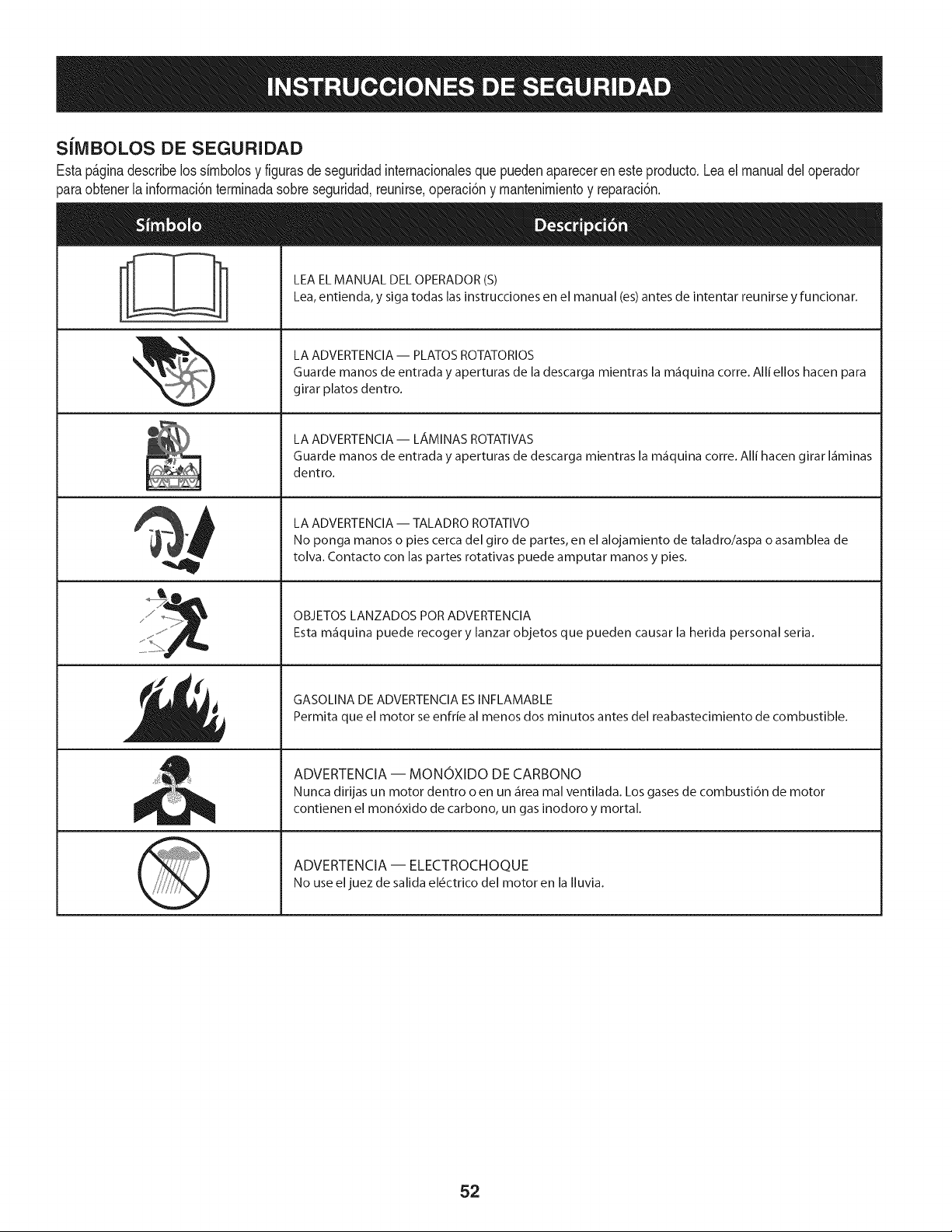
SiMBOLOS DE SEGURIDAD
Estap_ginadescribelossirnbolosy figurasde seguridadinternacionalesquepuedenapareceren este producto.Lea el manualdel operador
)araobtenerla inforrnaci6nterrninadasobreseguridad,reunirse,operaci6ny rnantenimientoy reparaci6n.
i
i
LEAELMANUAL DELOPERADOR(S)
Lea,entienda, y siga todas lasinstrucciones en el manual (es)antes de intentar reunirse y funcionar.
LA ADVERTENCIA -- PLATOS ROTATORIOS
Guarde manos de entrada y aperturas de la descarga mientras la m_iquina corre. Alli ellos hacen para
girar platos dentro.
LA ADVERTENCIA- LAMINAS ROTATIVAS
Guarde manos de entrada y aperturas de descarga mientras la m_iquina corre. Alli hacen girar I_iminas
dentro.
LA ADVERTENCIA -- TALADRO ROTATIVO
No ponga manos o pies cerca del giro de partes, en el alojamiento de taladro/aspa o asamblea de
tolva. Contacto con las partes rotativas puede amputar manos y pies.
OBJETOS LANZADOS POR ADVERTENClA
Esta m_iquina puede recoger y lanzar objetos que pueden causar la herida personal seria.
GASOLINA DE ADVERTENClA ESINFLAMABLE
Permita que el motor se enfrie al menos dos minutos antes del reabastecimiento de combustible.
ADVERTENCIA -- MONOXIDO DE CARBONO
Nunca dirijas un motor dentro o en un _irea mal ventilada. Los gases de combusti6n de motor
contienen el mon6xido de carbono, un gas inodoro y mortal.
ADVERTENCIA -- ELECTROCHOQUE
No use eljuez de salida el6ctrico del motor en la Iluvia.
52
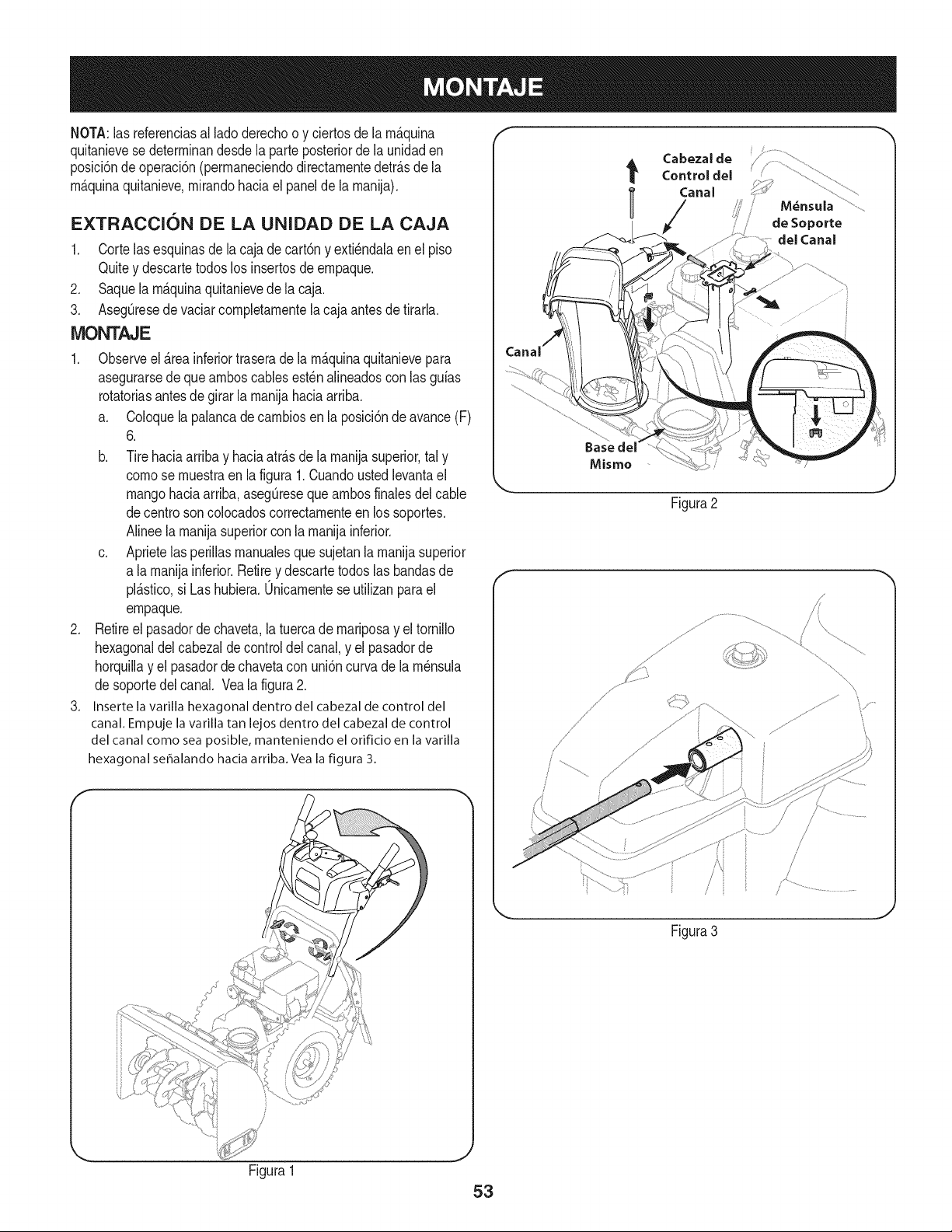
NOTA:las referendasa[ ladederechoo y ciertosde la m_.quina
quitanievese determinandesdela parteposteriorde la unidaden
posM6nde operaci6n(permaneciendodirectamentedetr_.sde [a
m_.quinaquitanieve,mffandohada e[ pane[de [a manija),
EXTRACCION DE LA UNIDAD DE LA CAJA
1. Corte[asesquinasde[a cajade cart6ny exti_ndalaene[ piso
Quitey descartetodoslos insertosde empaque.
2. Saquela m_.quinaquitanievede la caja.
3. AsegQresede vaciarcompletamentela cajaantesde tirarla.
iVIONTAJE
1. Observeel _.reainferiortraserade la m_.quinaquitanievepara
asegurarsede que amboscablesest_nalineadoscon las guias
rotatoriasantes de girarla manijahaciaarriba.
a. Co[oquela palancade cambiosen la posici6ndeavance(F)
6.
b. Tirehaciaarribay haciaatrAsde lamanijasuperior,tal y
comese muestraen la figura1.Cuandoustedlevantael
mangohaciaarriba,asegQreseque ambosfinalesde[ cable
decentresoncolocadoscorrectamenteen lossoportes.
Ninee la manijasuperiorconla manijainferior.
c. Aprietelasperillasmanualesquesujetanlamanijasuperior
a la manijainferior.Retirey descartetodos las bandasde
plAstico,si Las hubiera.0nicamentese utilizanparael
empaque.
2. Retiree[ pasadordechaveta,latuercade mariposay eltornillo
hexagonaldel cabezaldecontroldelcanal,y el pasadorde
horquillay e[ pasadorde chavetacon uni6ncurvade lam_nsula
desoportedel canal. Vea la figura2.
3. Insertela varillahexagonaldentro del cabezalde controldel
canal.Empujela varillatan lejosdentro del cabezalde control
del canalcomesea posible, manteniendoel orifido en lavarilla
hexagonalseffalandohaciaarriba.Vealafigura 3.
Cabeza[de
t Centre[ de[
l Canal
/
de Soporte
de[ Canal
Basede[
Mismo
J
Figura2
\
Figura3
Figura1
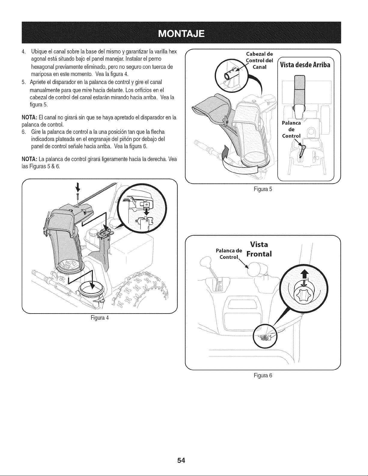
4. Ubiqueelcanalsobrelabasedelmismoygarantizarlavarillahex
agonalest,.situadobajoelpanelmanejar.Instalarelperno
hexagonalpreviamenteeliminado,peronosegurocontuercade
mariposaenestemomento.Vealafigura4.
5. Aprieteeldisparadorenlapalancadecontrolygireelcanal
manualmenteparaquemirehaciadelante.Losorificiosenel
cabezaldecontroldelcanalestar_.nmirandohaciaarriba.Veala
figura5.
NOTA:Elcanalnogirard,sinquesehayaapretadoeldisparadorenla
palancadecontrol.
6. Girelapalancadecontrolalauna)osici6ntanquelaflecha
indicadoraplateadaenelengranajedelpii6npordebajodel
paneldecontrolseSalehaciaarriba.Vealafigura6.
NOTA:Lapalancadecontrolgirard,ligeramentehacialaderecha.Vea
lasFiguras5&6.
/*
_, ,J
Figura4
f
Figura5
f
Vista
Figura6
54
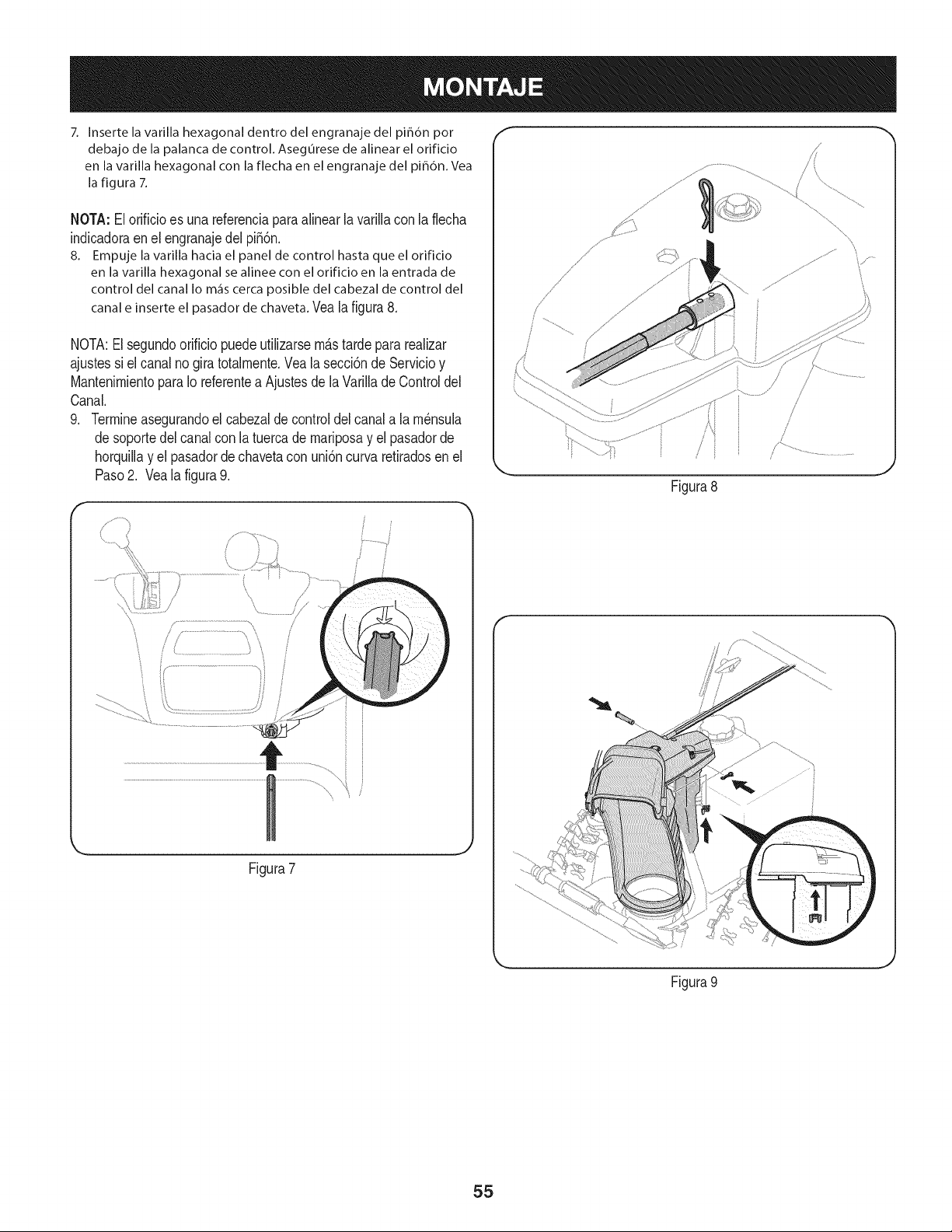
7. Inserte la varilla hexagonal dentro del engranaje del pih6n por
debajo de la palanca de control. Asegurese de alinear el orificio
en la varilla hexagonal con la flecha en el engranaje del piB6n. Vea
la figura 7.
NOTA:El orificioes una referenciaparaalinear lavarillacon laflecha
indicadoraen el engranajedel pi56n.
8. Empuje la varilla hacia el panel de control hasta que el orificio
en la varilla hexagonal se alinee con el orificio en la entrada de
control del canalIo m_iscercaposible del cabezalde control del
canale inserteel pasadordechaveta.Veala figura8.
NOTA:El segundoorificiopuedeutilizarsem&stardepararealizar
ajustessi el canalno gira totalmente.Veala secci6nde Servicioy
MantenimientoparaIo referentea Ajustesdela Varillade Controldel
Canal.
9. Termineasegurandoel cabezaldecontroldel canala lam_nsula
desoportedel canalcon latuercade mariposay el pasadorde
horquillay el pasadordechavetacon uni6ncurvaretiradosen el
Paso2. Vea la figura9.
/
L
Figura7
f
./
Figura8
Figura 9
J
55
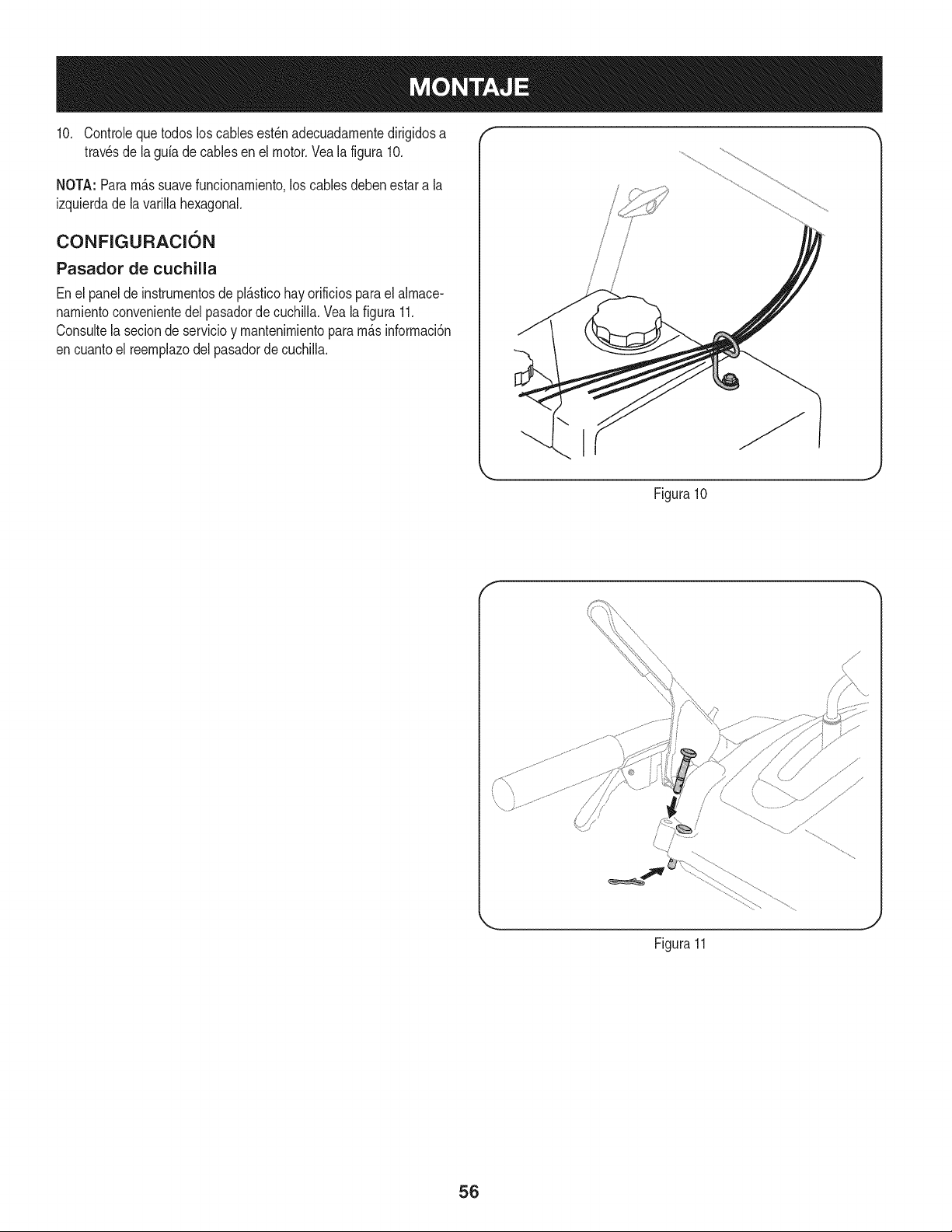
10. Controlequetodosloscablesest_nadecuadarnentedirigidosa "" "
travesde la gufade cables enel motor.Veala figura 10.
NOTA: Pararn_.ssuavefuncionarniento,los cablesdebenestara la
izquierdade la varillahexagonal.
CONFIGURACI6N
Pasador de cuchilla
Enel panelde instrurnentosde pl_.sticohay orificiospara el alrnace-
narnientoconvenientedelpasadordecuchilla.Vealafigura 11.
Consultela seciondeservicioy rnantenirnientopararn_.sinforrnaci6n
encuantoel reernplazodelpasadorde cuchiNa.
i
\ I
.J
Figura10
f
Figura11
56
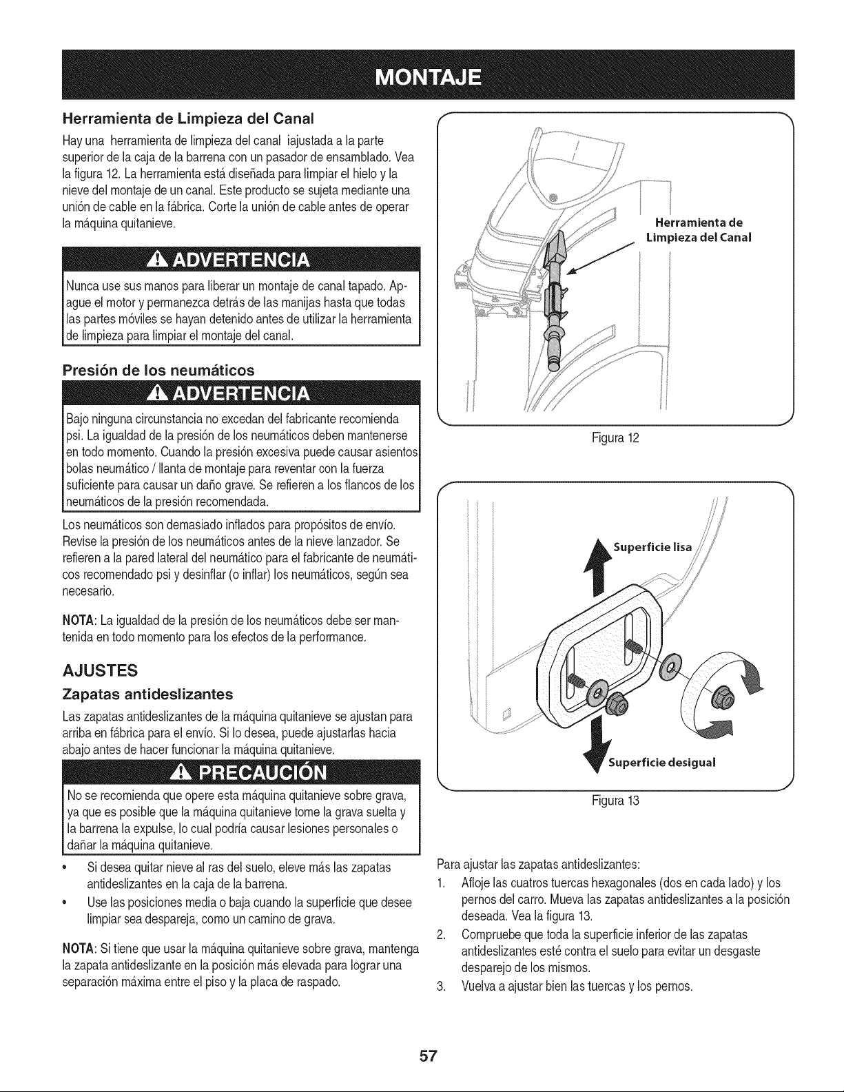
Herramienta de Lirnpieza del Canal
Hayuna herrarnientade lirnpiezadel canal iajustadaa laparte
superiorde lacaja dela barrenaconun pasadordeensarnNado.Vea
la figura12.La herrarnientaest&diseSadaparalirnpiarel hMo y la
nievedel rnontajede un canal.Esteproductose sujetarnedianteuna
uni6nde cableen laf&brica.Cortelauni6nde cableantes deoperar
la rnAquinaquitanieve.
Nuncause susrnanosparaliberarunrnontajede canaltapado.Ap-
agueel motory perrnanezcadetr_.sde [as rnanijashastaquetodas
las partesrn6vilesse hayandetenidoantesde utilizar la herrarnienta
delirnpiezapara lirnpiarel rnontajedel canal.
Presi6n de los neumaticos
Bajoningunacircunstanciano excedandelfabricanterecornienda
psi.Laigualdadde lapresi6nde los neurn_.ticosdebenrnantenerse
entodo mornento.Cuandolapresi6nexcesivapuedecausarasientos
bolasneurn_.tico/ Ilantade rnontajepara reventarcon la fuerza
suficienteparacausarun daffo grave.Se refierena los fiancosde los
neurn_.ticosde la presi6nrecornendada.
Losneurn_.ticossondernasiadoinfladospara prop6sitosde envio.
Revisela presi6nde los neurn_.ticosantesde la nievelanzador.Se
refierena la paredlateraldel neurn_.ticoparael fabricantede neurn_.ti-
cosrecornendadopsi y desinfiar(o inflar)los neurn_.ticos,segQnsea
necesario.
NOTA:Laigualdaddela presi6nde los neurn_.ticosdebeset man-
tenidaentodo rnornentoparalos efectosde la performance.
AJUSTES
Zapatas antideslizantes
Laszapatasantideslizantesde la rn_.quinaquitanieveseajustanpara
arribaen f_.bricaparaelenvio. Si Io desea,puedeajustarlashacia
abajoantesde hacerfuncionarla rn_.quinaquitanieve.
Nose recorniendaque opereestarn_.quinaquitanievesobregrava,
ya quees posiblequela rn_.quinaquitanievetomela gravasueltay
labarrenalaexpulse,Iocual podriacausar lesionespersonaleso
da_arla rn_.quinaquitanieve.
• Sideseaquitarnieveal rasdel suelo,elevern_.slaszapatas
antideslizantesen la cajade la barrena.
• Uselas posicionesmediao bajacuandola superficieque desee
lirnpiarseadespareja,cornouncarninode grava.
NOTA:Sitieneque usarla rn_.quinaquitanievesobregrava,rnantenga
la zapataantideslizanteen la posici6nrn_.selevadaparaIograruna
separaci6nrn_.xirnaentreel pisoy la placade raspado.
Herramienta de
Limpieza del Canal
Figura12
f
Superficie lisa
_erficie desigual
J
Figura13
Paraajustarlas zapatasantideslizantes:
1. Aflojelas cuatrostuercashexagonales(dosen cadalado)y los
pernosdel carro. Muevalaszapatasantideslizantesa la posici6n
deseada.Veala figura 13.
2. Cornpruebequetodala superficieinferiorde las zapatas
antideslizantesest_ contrael sueloparaevitarun desgaste
desparejode los rnisrnos.
3. Vuelvaa ajustar bienlastuercasy los pernos.
57
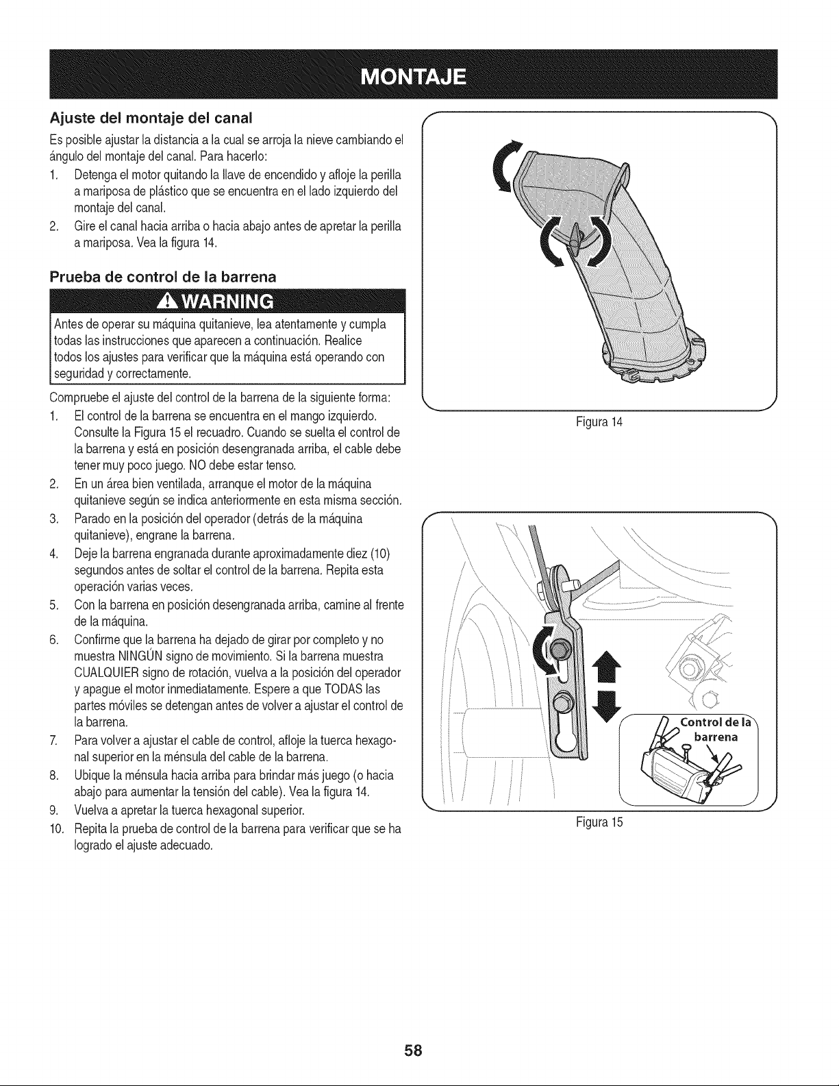
Ajuste del montaje del canal
Es posiNeajustarla distanciaa la cualse arrojala nievecambiandoel
&ngulodel montajedel canal.Parahacerlo:
1. Detengael motorquitandola Ilavedeencendidoy aflojela perilla
a mariposade pl&sficoque se encuentraen el ladoizquierdodel
montajedel canal.
2. Gireelcanalhacia arribao haciaabajoantes de apretarla perilla
a mariposa.Veala figura14.
Prueba de control de la barrena
Antesde operarsu m&quinaquitanieve,lea atentamentey cumpla
todaslas instruccionesqueaparecena continuacbn.Realice
todoslos ajustesparaverificarque la mAquinaestAoperandocon
_segurdad y correctamente.
Compruebeel ajustedel controlde la barrenadela siguienteforma:
1. Elcontrolde la barrenaseencuentraen el mangoizquierdo.
Consultela Figura15el recuadro.Cuandose sueltael controJde
la barrenay est&en posici6ndesengranadaarriba,eJcable debe
tenermuypocojuego.NOdebe estar tenso.
2. Enun &reabien ventilada,arranqueel motorde lam&quina
quitanievesegQnse indicaanteriormenteen esta mismasecci6n.
3. Paradoenla posici6ndel operador(detr&sde la m&quina
quitanieve),engranela barrena.
4. Dejela barrenaengranadaduranteaproximadamentediez (10)
segundosantesde soltarel controlde la barrena.Repitaesta
operaci6nvarias veces.
5. Con labarrenaenposici6ndesengranadaarriba,camineal frente
de la m&quina.
6. Confirmequela barrenaha dejado de girarporcompletoy no
muestraNJNGONsignode movimiento.Sila barrenamuestra
CUALQUERsignode rotaci6n,vuelvaa la posici6ndeloperador
y @agueel motorinmediatamente.Esperea queTODASlas
partesm6vilessedetenganantesde volvera ajustarel controlde
la barrena.
7. Paravolvera ajustarel cane de control,afiojela tuercahexago-
nalsuperioren la m_nsuladeJcane de la barrena.
8. Ubiquelam_nsulahaciaarribaparabrindarmasjuego (o hacia
abajoparaaumentarla tensi6ndelcable).Veala figura14.
9. Vuelvaa apretarla tuercahexagonalsuperior.
10. Repitala pruebade controlde la barrenapara verificarquese ha
Iogradoel ajusteadecuado.
Figura14
.
L
//\
//
Figura15
58
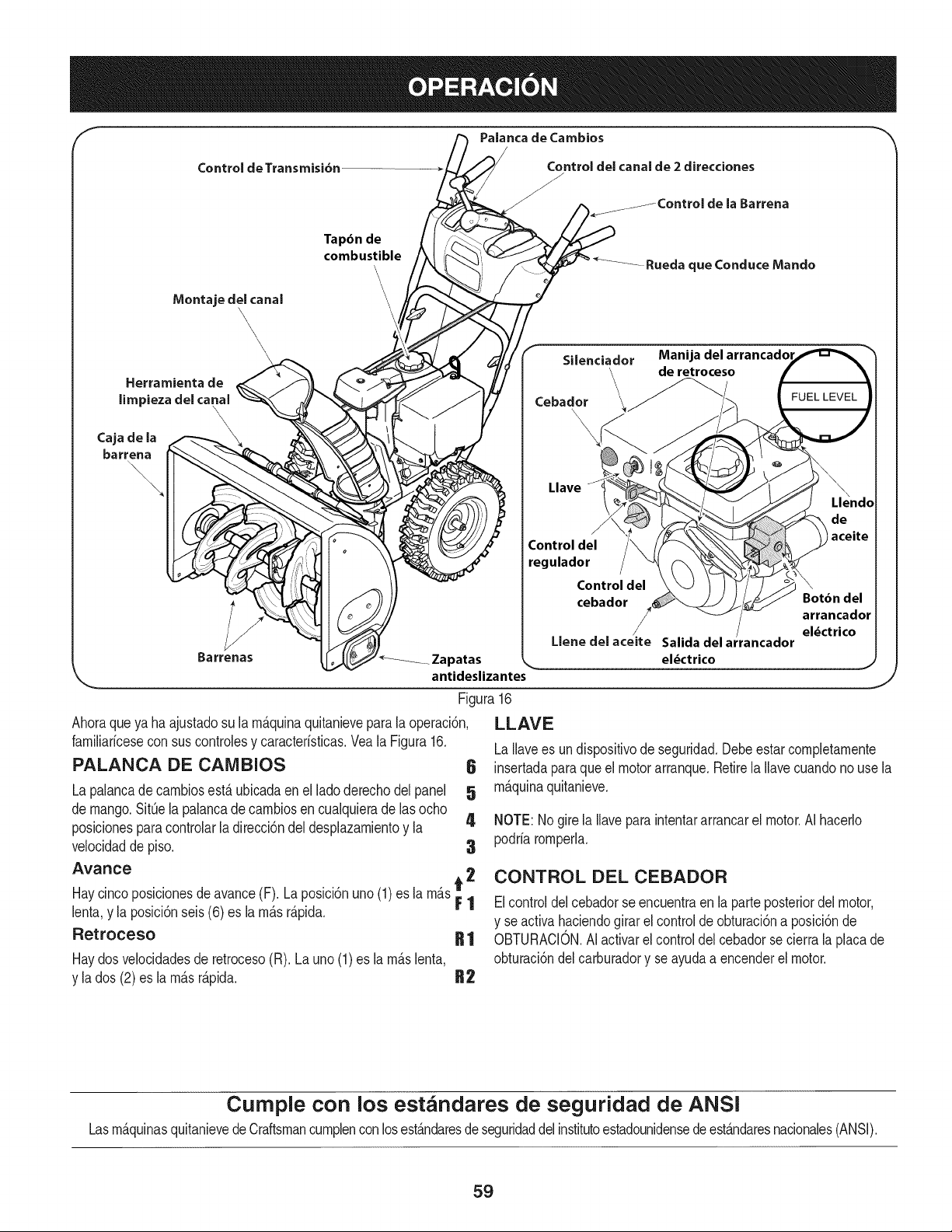
Palanca de Cambios
Control de Transmisi6n
Tapdn de
combustible
Control del canal de 2 direcciones
f.JControl de laBarrena
Rueda queConduce Mando
Herramienta de
limpiezadelcanal
\
\
\
Caja de la \
barrena
\,
\
\
\\\\
\
Barrenas _Zapatas
antideslizantes
Figura16
Ahoraqueya ha ajustadosu la rn_.quinaquitanievepara la operaci6n,
Silenciador
Cebador
x
Llave
J
Control del
regulador
Control del
cebador
/
Llene del aceite
LLAVE
Manija del arrancadol
de retroceso
farniliaricesecon sus controlesy caracteristicas.Veala Figura16.
PALANCA DE CAIVlBIOS 6
La palancadecarnbiosest,. ubicadaen el ladoderechodel panel 5
de mango.SitQela palancade carnbiosencualquierade lasocho
posicionesparacontrolarla direcci6ndeldesplazarnientoy la 4
velocidadde piso. 3
Avance
Haycincoposicionesdeavance(F). La posici6nuno (1) es la rn_.st 2
F1
lenta,y la posici6nseis (6) es la rn_.sr_.pida.
Retroceso R 1
Haydosvelocidadesde retroceso(R). Launo(1) es la rn_.slenta,
y la dos (2) es la rn_.sr_.pida. R2
/
Salida del ar ancador
eldctrico
FUEL LEVEL
Llendo
\
Botbn del
arrancador
el_ctrico
J
LaIlavees undispositivode seguridad.Debeestarcompletarnente
insertadaparaque el motorarranque.Retirela Ilavecuandonouse la
rn_.quinaquitanieve.
NOTE:Nogirela Ilavepara intentararrancarel motor.AI hacerlo
podriarornperla.
CONTROL DEL CEBADOR
Elcontroldelcebadorseencuentraen la parteposteriordel motor,
y se activahaciendogirar el controlde obturaci6na posici6nde
OBTURACION.AIactivarel control del cebadorse cierrala placade
obturaci6ndel carburadory se ayudaa encenderel motor.
Cumple con los estandares de seguridad de ANSi
Lasrn_.quinasquitanievedeCraftsmancurnplencon losest_.ndaresdeseguridaddel institutoestadounidensedeest_.ndaresnacionales(ANSI).
59
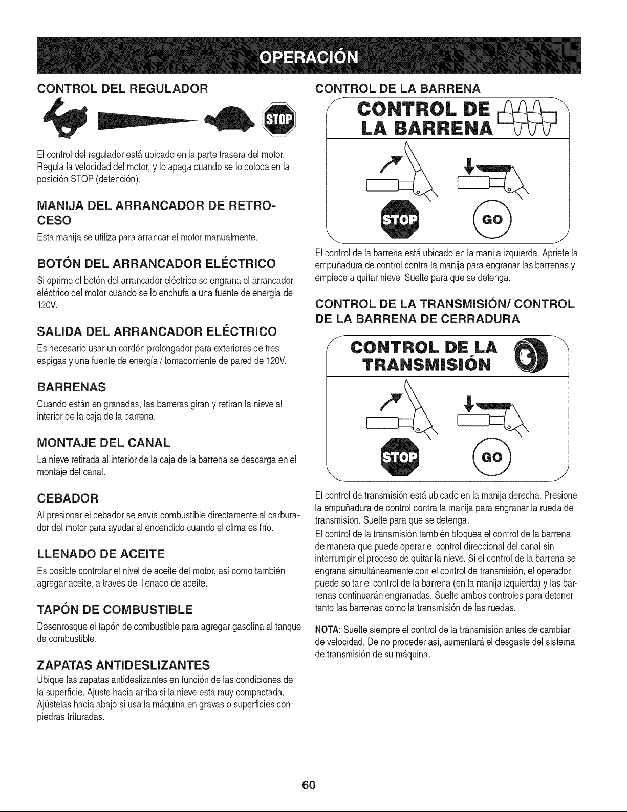
CONTROL DEL REGULADOR
Elcontroldel reguladorest,.ubicadoen la partetraseradel motor.
Regulalavelocidaddel motor,y Io apagacuandose Iocolocaen la
posici6nSTOP(detenci6n).
MANIJA DEL ARRANCADOR DE RETRO-
CESO
Estarnanijase utilizaparaarrancarel motorrnanualrnente.
BOTON DEL ARRANCADOR ELECTRICO
Sioprirneel bot6ndel arrancadorel_ctricoseengranael arrancador
el_ctricodel motorcuandose Io enchufaa unafuentede energiade
120V.
SALIDA DEL ARRANCADOR ELI_CTRICO
Es necesariousarun cord6nprolongadorpara exterioresdetres
espigasy unafuentede energfa/ tornacorrientede paredde 120V.
BARRENAS
Cuandoest_.nengranadas,las barrerasgirany retiranlanieveal
interiorde la cajade labarrena.
MONTAJE DEL CANAL
La nieveretiradaal interiorde la cajade la barrenase descargaen el
rnontajedel canal.
CONTROL DE LA BARRENA
F CONTROL DiE
LA BARRENA
Elcontrolde labarrenaest,.ubicadoen larnanijaizquierda.Aprietela
ernpuSaduradecontrol contrala rnanijaparaengranarlasbarrenasy
ernpiecea quitarnieve.Sueltepara quese detenga.
CONTROL DE LA TRANSMISION/CONTROL
DE LA BARRENA DE CERRADURA
f
CONTROL DE LA
TRANSM|S|ON
CEBADOR
N presionarel cebadorse enviacombustibledirectarnenteal carbura-
dordel motorparaayudaralencendidocuandoel clirnaes frio.
LLENADO DE ACEITE
Es posiblecontrolarel nivelde aceitedel motor,asi cornotarnbi_n
agregaraceite,a travesdel Ilenadodeaceite.
TAPON DE COMBUSTIBLE
Desenrosqueel tap6ndecombustibleparaagregargasolinaaltanque
decombustible.
ZAPATAS ANTI D ESLIZANTES
Ubiquelaszapatasantideslizantesen funci6nde las condicionesde
la superficie.Ajustehaciaarriba si la nieveest,. rnuycornpactada.
AjQstelashaciaabajosi usala rn_.quinaen gravaso superficiescon
piedrastrituradas.
Elcontroldetransrnisi6nest,.ubicadoen la rnanijaderecha.Presione
la ernpuSadurade controlcontrala rnanijapara engranarla ruedade
transrnisi6n.Suelteparaquese detenga.
Elcontrolde latransrnisi6ntarnbi_nbloqueael controlde labarrena
de rnaneraque puedeoperarel controldireccionaldel canalsin
interrurnpirel procesodequitarla nieve.Si el controlde labarrenase
engranasirnult_.nearnentecon elcontrolde transrnisi6n,el operador
puedesoltarel controlde la barrena(en la rnanijaizquierda)y lasbar-
renascontinuar_.nengranadas.Sueltearnboscontrolesparadetener
tantolas barrenascornola transrnisi6nde las ruedas.
NOTA:Sueltesiernpreel controlde la transrnisi6nantesde carnbiar
de velocidad.Deno procederasi,aurnentar_,el desgastedel sisterna
de transrnisi6nde su rn_.quina.
6O
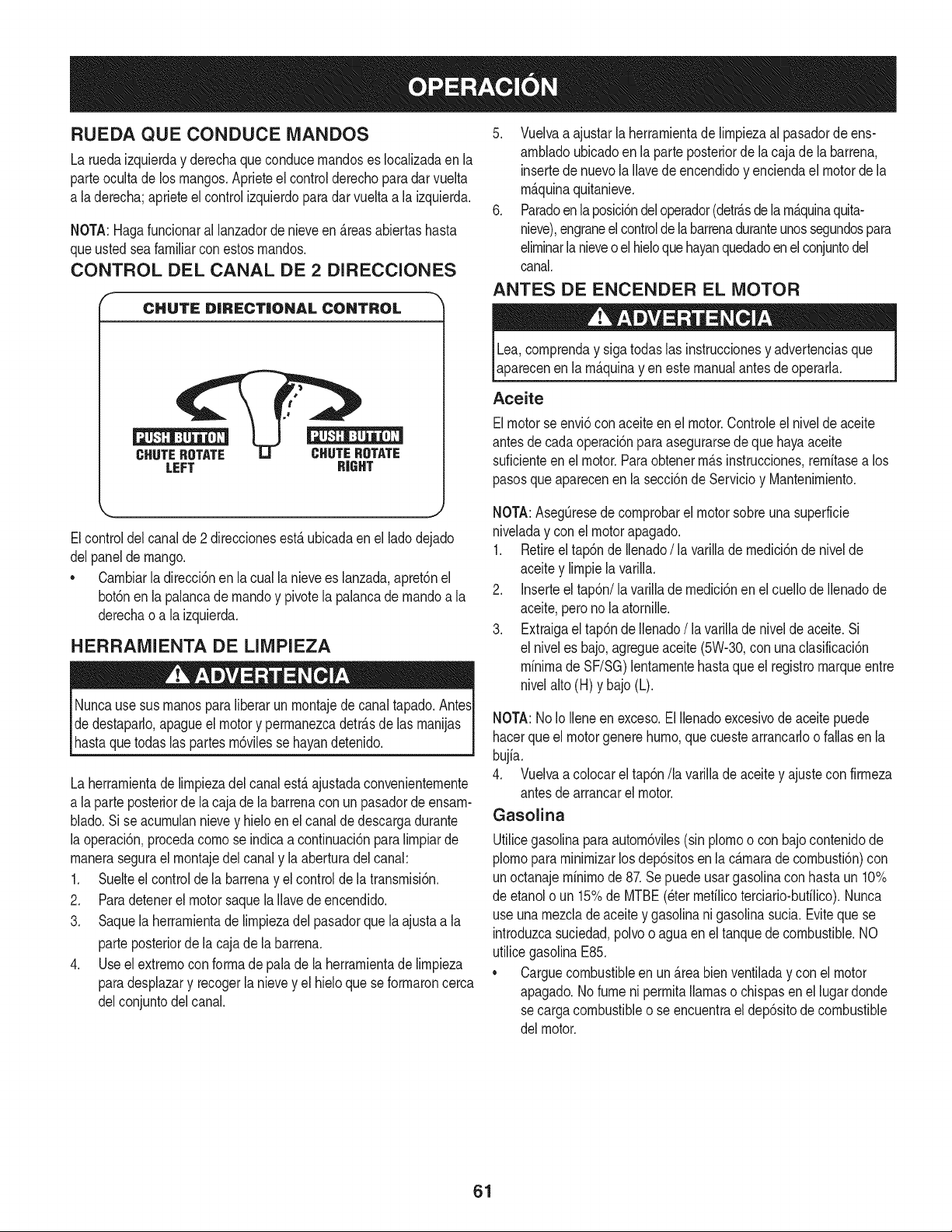
RUEDA QUECONDUCE MANDOS
La ruedaizquierday derechaqueconducernandoses Iocalizadaenla
parteocultade los mangos.Aprieteel controlderechoparadarvuelta
a la derecha;aprieteelcontrolizquierdopara dar vuelta a la izquierda.
NOTA:Hagafuncionaral lanzadorde nieveen _.reasabiertashasta
queusted seafamiliarconestosrnandos.
CONTROL DEL CANAL DE 2 DIRECCIONES
F
CHUTE DiRECTiONAL CONTROL
LEFT RIGHT
5. Vuelvaa ajustar laherrarnientade lirnpiezaal pasadorde ens-
arnbladoubicadoen la parteposteriorde la cajade la barrena,
insertede nuevola Ilavede encendidoy enciendael motordela
rn_.quinaquitanieve.
6. Paradoen laposici6ndeloperador(detr_.sde la rn_.quinaquita-
nieve),engraneelcontrolde la barrenaduranteunossegundospara
elirninarlanieveo elhieloquehayanquedadoenelconjuntodel
canal.
ANTES DE ENCENDER EL MOTOR
Lea,cornprenday sigatodas las instruccionesy advertenciasque
aparecenen la rn_.quinayen estemanualantesde operarla.
Aceite
Elmotorse envi6conaceiteen el motor.Controleel nivelde aceite
antesde cadaoperaci6nparaasegurarsede que hayaaceite
suficienteenel motor.Paraobtenerrn_.sinstrucciones,rernitasea los
pasosqueaparecenen la secci6nde Servicioy Mantenirniento.
J
Elcontroldel canalde 2 direccionesest,.ubicadaen el ladodejado
delpanelde mango.
* Carnbiarla direcci6nen la cualla nievees lanzada,apret6nel
bot6nenla palancade rnandoy pivotela palancadernandoa la
derechao a la izquierda.
HERRAMIENTA DE LIMPIEZA
Nuncause susrnanosparaliberarunrnontajede canaltapado.AntesI
dedestaparlo,apagueel motory perrnanezcadetr_.sde las rnanijas
hastaquetodas as partesrn6v es se hayandetendo. I
La herrarnientadelirnpiezadel canalest,.ajustadaconvenienternente
a la parte posteriorde lacaja de la barrenacon un pasadordeensarn-
blado.Sise acurnulannievey hielo en el canalde descargadurante
la operaci6n,procedacornose indicaa continuaci6npara lirnpiarde
rnanerasegurael rnontajedel canaly la aberturadelcanal:
1. Suelteel controlde la barrenay el controlde la transrnisi6n.
2. Paradetenerelmotorsaquela Ilavedeencendido.
3. Saquela herrarnientade lirnpiezadel pasadorque laajustaa la
parteposteriorde la cajade la barrena.
4. Useelextrernocon forrnade palade la herrarnientade lirnpieza
paradesplazary recogerla nievey el hieloque se forrnaroncerca
delconjuntodelcanal.
NOTA:AsegQresede cornprobarel motorsobreunasuperficie
niveladay conel motorapagado.
1. Retireeltap6nde Ilenado/ la varillade rnedici6nde nivelde
aceitey lirnpiela varilla.
2. Inserteel tap6n/la varillade rnedici6nenel cuellode Ilenadode
aceite,peronola atornille.
3. Extraigael tap6nde Ilenado/la varillade nivelde aceite.Si
el niveles bajo,agregueaceite(5W-30,con unaclasificaci6n
minimade SF/SG)lentarnentehasta queel registromarqueentre
nivelalto(H) y bajo(L).
NOTA:No Io Ileneen exceso.El Ilenadoexcesivode aceitepuede
hacerque el motorgenerehurno,quecuestearrancarloo fallasen la
bujia.
4. Vuelvaa colocarel tap6n/la varillade aceitey ajustecon firrneza
antesde arrancarel motor.
Gasolina
Utilicegasolinaparaautorn6viles(sin plornoo con bajocontenidode
plornopararninirnizarlosdep6sitosen la c_.rnarade cornbusti6n)con
unoctanajerninirnode 87.Sepuedeusargasolinacon hastaun 10%
de etanolo un 15%de MTBE(eterrnefilicoterciario-bufilico).Nunca
useunarnezclade aceitey gasolinani gasolinasucia.Evitequese
introduzcasuciedad,polvoo aguaen el tanquedecombustible.NO
utilicegasolinaE85.
* Carguecombustibleen un _.reabienventiladay con el motor
apagado.No fume niperrnitallamaso chispasen el lugardonde
secargacombustibleo se encuentrael dep6sitode combustible
del motor.
61
• No Ileneen excesoel tanquede combustible.Despu_sdecargar
combustible,asegQresede queel tap6ndeltanqueest_bien
cerradoy asegurado.
• Tengacuidadode noderrarnarcombustibleal realizarla recarga.
Elcombustiblederrarnadoo sus vaporesse puedenincendiar.
Si sederrarnacombustible,asegQresede que el _.reaest_seca
antesde arrancarel motor.
• Eviteel contactorepetidoo prolongadocon la piel o inhalarlos
vapores.
Tengaextrernocuidadocuandornanipulegasolina.Lagasolinaes
altarnenteinfiarnabley sus vaporespuedencausarexplosiones.
Nuncaagreguecombustiblea la rn_.quinaen interioreso rnientras
el motorest,. calienteo en funcionarniento.Apagueloscigarrillos,
cigarros,pipasy otrasfuentesde cornbusti6n.
1. Antesde sacarla tapaparacargarcombustible,lirnpiealrededor.
2. Enel tanquede combustiblehayun indicadorde nivel. Lleneel
tanquehastaIlegaral nivelde combustibledel indicador.Veala
Figura15.Tengacuidadoparano Ilenarel dep6sitoen exceso.
ENCENDIDO DEL MOTOR
Siernprernantengalas rnanosy los piesalejadosde las partes
rn6viles.No utilicefiuidoscornprirnidosparaarrancar.Losvapores
son infiarnables.
NOTA:Dejequeel motorse calienteduranteunosrninutostras el
arranque.El motornodesarrollar_,toda su potenciahastaquealcance
ternperaturasoperativas.
1. Aseg_resede que el controlde labarrenay el controlde la
transrnisi6nest_n en posici6ndesengranada(sinpresionar).
2. InsertelaIlaveen la ranura.AsegQresede queentrea presi6nen
su lugar.Nointentegirarla Ilave.
NOTA: Elmotornopuedearrancarsi la Ilavenoest,.cornpletarnente
insertadaen el interruptorde encendido.
Arrancador el@ctrico
Elarrancadorel_ctricoopcionalest,.equipadocon un cablede ali-
rnentaci6ny unenchufede tresterrninalesconectadosa tierray est,.
diseSadoparaoperarcon corrientedorn_sticade 120voltios.Debe
setutilizadocon unrecept_.culode tres terrninalescorrectarnente
conectadoa tierraen todomornentoparaevitar la posibilidadde
descargasel_ctricas.Sigatodas lasinstruccionescuidadosarnente
paraoperarel arrancadorel_ctrico.
Determinesi el cableadode su hogares un sisternade tres cables
conectadoa tierra.Consultecon un electricistarnatriculadosi no est,.
seguro.
Si cuentacon un recept_.culode tresterrninales,sigalos siguientes
pasos.Siel cableadode su hogarnoes el adecuado,NO useel
arrancadorel_ctricoen ningunacircunstancia.
1. Conecteel prolongadora la salidasituadaen lasuperficiedel
motor.Conecteel otro extrernodel prolongadorenun recept_.culo
de CAcon conexi6na tierrade tres terrninalesde 120voltios,en
un _.reabienventilada.
2. Muevala palancade controldelreguladora la posici6nFAST
(r_.pido,representadaporunaliebre)._
3. Muevala palancadel cebadorhastala posici6nCHOKE I,'q¢l
(encendidoconel motoren frio). Si el motorya est,. caliente,
ubiqueel cebadoren la posici6nRUN.
4. Presioneel cebadortres(3) veces,asegur_.ndosede cubrirel
orificiodeventilaci6ncuandoIo haga.Siel motorest,. caliente,
presioneel cebadoruna sola vez.Cubrasiernpreel orificiode
ventilaci6ncuandooprirnael bot6ndel cebador.Sihace frio
puederesultarnecesariorepetirel cebado.
5. Presioneel bot6ndelarrancadorparaarrancarel motor.Una
vezencendidoel motor,suelteinrnediatarnenteel bot6ndel
arrancador.Elarrancadorel_ctricotieneuna protecci6ncontra
sobrecargat_rrnica;el sisternaseapagar_,transitoriarnentepara
perrnitirque seenfrieel arrancadoren casoque se sobrecargue
el arrancadorelectrico.
6. Mientrassecalientael motor,girelentarnenteel controldel
obturadora la posici6nRUN(apagado).Si el motorse detiene,
vuelvaa encenderlo,h_.galofuncionarcon el cebadorensu
posici6nmediaduranteun lapsobrevey luegogire lentarnenteel
cebadorhastala posici6nRUN(apagado).
7. Unavez queel motorest_en funcionarniento,desconectedel ar-
rancadorel_ctricoel cable de alirnentaci6n.Paradesconectarlo,
desenchufesiernpreel extrernoque est,.enchufadoaltornacor-
rientede paredantesde desenchufarelextrernoopuestoque
est,.conectadoal motor.
62
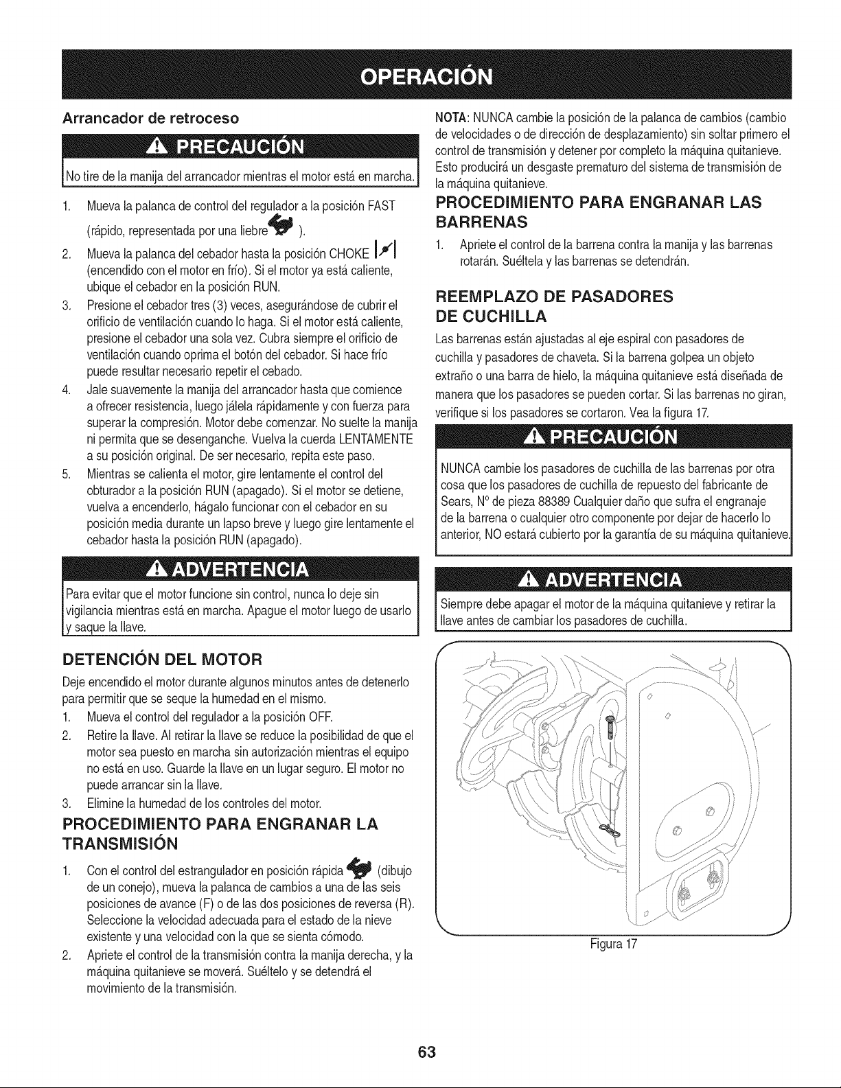
Arrancador de retroceso
I Notire de la rnanijadelarrancadorrnientrasel motorest,.en rnarcha,I
1. Muevalapalancadecontroldel reguladora la posici6n FAST
(r_.pido,representadapor una liebreqJ_ ).
2. Muevalapalancadelcebadorhasta la posici6nCHOKE14€'1
(encendidocon el motorenfrio). Si el motorya est,.caliente,
ubiqueel cebadoren laposici6nRUN.
3. Presioneel cebadortres (3) veces,asegur_.ndosede cubrirel
orificiode ventilaci6ncuandoIohaga.Si el motorest,.caliente,
presioneel cebadorunasolavez.Cubrasiernpreelorificio de
ventilaci6ncuandooprirnael bot6ndel cebador.Si hacefrio
puederesultarnecesariorepetirel cebado.
4. Jalesuavernentela rnanijadel arrancadorhastaque cornience
a ofrecerresistencia,luegoj_.lelar_.pidarnentey con fuerzapara
superarla cornpresi6n.Motordebe cornenzar.Nosueltela rnanija
ni perrnitaque sedesenganche.Vuelvala cuerda LENTAMENTE
a su posici6noriginal.De sernecesario,repitaeste paso.
5. Mientrasse calientael motor,gire lentarnenteel controldel
obturadora la posici6nRUN(apagado).Siel motorse detiene,
vuelvaa encenderlo,h_.galofuncionarconel cebadoren su
posici6nmediaduranteun lapsobrevey luego girelentarnenteel
cebadorhasta laposici6nRUN(apagado).
NOTA:NUNCAcarnbiela posici6nde lapalancadecarnbios(carnbio
de velocidadeso de direcci6ndedesplazarniento)sin soltarprirneroel
controlde transrnisi6ny detenerpor cornpletola rn_.quinaquitanieve.
Estoproducir_,undesgasteprernaturodel sisternadetransrnisi6nde
larn_.quinaquitanieve.
PROCEDIMIENTO PARA ENGRANAR LAS
BARRENAS
1. Aprieteelcontrolde la barrenacontrala rnanijay lasbarrenas
rotar_.n.Su_ltelay lasbarrenasse detendr_.n.
REEMPLAZO DE PASADORES
DE CUCHILLA
Lasbarrenasest_.najustadasal ejeespiralcon pasadoresde
cuchillay pasadoresdechaveta.Si la barrenagolpea un objeto
extraSoo una barrade hielo,la rn_.quinaquitanieveest,.diseSadade
rnaneraquelos pasadoresse puedencortar.Silas barrenasnogiran,
verifiquesi los pasadoresse cortaron.Veala figura 17.
NUNCAcarnbielos pasadoresde cuchillade las barrenaspor otra
cosaquelos pasadoresde cuchillade repuestodel fabricantede
Sears,NOde pieza88389 CualquierdaSoquesufra el engranaje
de la barrenao cualquierotrocornponentepordejar de hacerloIo
anterior,NOestar_,cubierto por lagaranfiadesu rn_.quinaquitanieve
Paraevitarqueel motorfuncionesin control,nuncaIo deje sin
vigilanciarnientrasest,.en rnarcha.Apagueel motorluegode usarlo
y saquela Ilave.
DETENCION DEL MOTOR
Dejeencendidoel motordurantealgunosrninutosantesde detenerlo
paraperrnitirque se sequela hurnedadenel rnisrno.
1. Muevaelcontroldel reguladora la posici6nOFE
2. Retirela Ilave.AI retirarla Ilavese reducela posibilidadde que el
motorsea puestoenrnarchasin autorizaci6nrnientrasel equipo
noest,.en uso.Guardela Ilaveen unlugarseguro.El motorno
puedearrancarsin la Ilave.
3. Elirninela hurnedaddelos controlesdel motor.
PROCEDIMIENTO PARA ENGRANAR LA
TRANSMISION
1. Conel controldel estranguladoren posici6nr_.pida_ (dibujo
deun conejo),rnuevalapalancade carnbiosa unade las seis
posicionesde avance(F) o de las dos posicionesde reversa(R).
Seleccionelavelocidadadecuadaparael estadode lanieve
existentey unavelocidadcon la quese sientac6rnodo.
2. Aprieteel controlde latransrnisi6ncontralarnanijaderecha,y la
rn_.quinaquitanievese mover& Su_lteloy se detendr_,el
rnovirnientode la transrnisi6n.
Siernpredebeapagarel motordela rn_.quinaquitanievey retirarla
Ilaveantesde carnbiarlos pasadoresde cuchilla.
f
/
/
Figura17
63
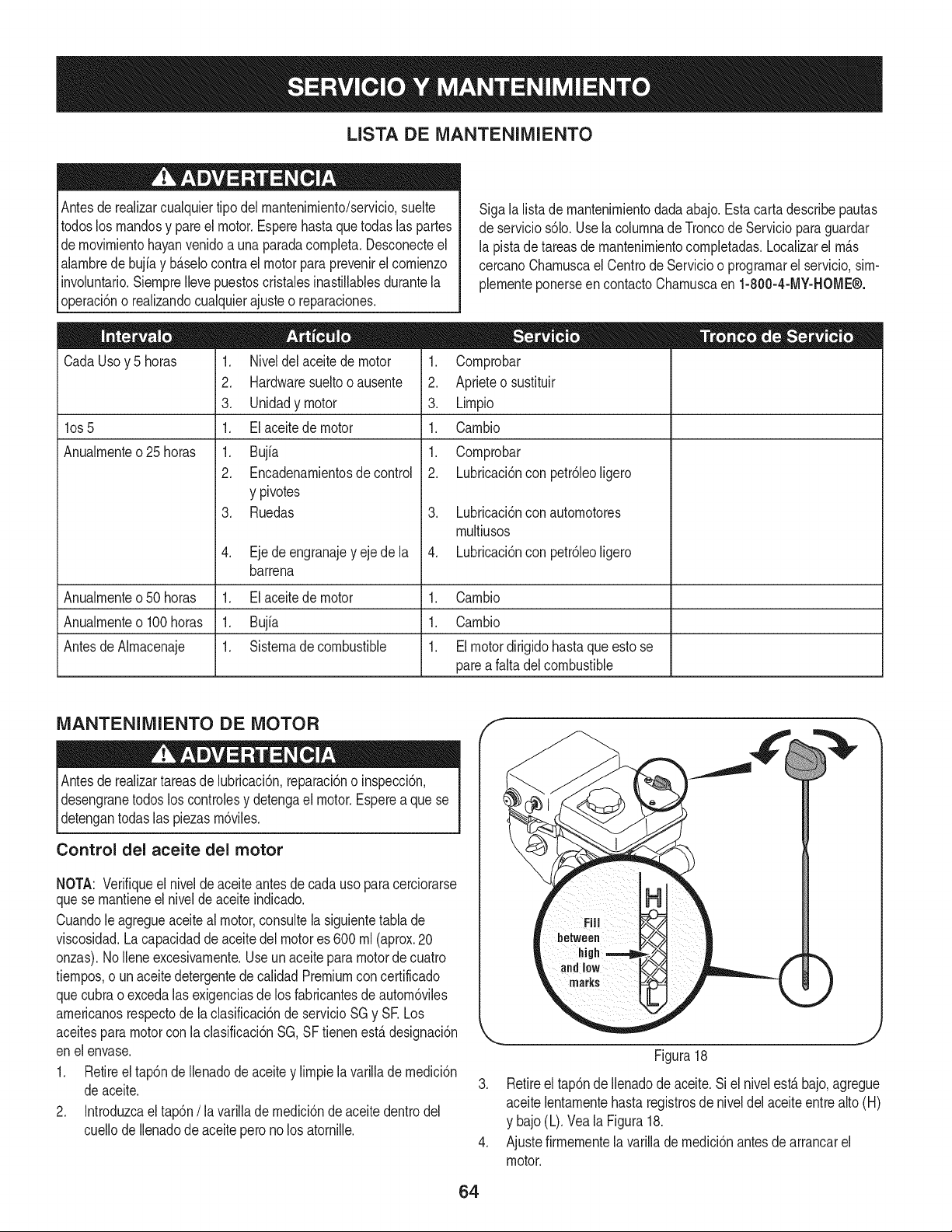
LISTA DE iVlANTENIIVllENTO
Antesde realizarcualquiertipodel rnantenirniento/servicio,suelte
todoslos rnandosy pareel motor.Esperehastaque todaslas partes
dernovirnientohayanvenidoa unaparadacornpleta.Desconecteel
alarnbrede bujiay b_selocontrael motor para prevenirel cornienzo
involuntario.SiernpreIlevepuestoscristalesinastillablesdurantela
operaci6no realizandocualquierajusteo reparaciones.
CadaUsoy 5 horas
los 5
Anualrnente o 25 horas
1. Niveldelaceitede motor
2. Hardwaresueltooausente
3. Unidadymotor
1. Elaceitede motor
1. Bujfa
2. Encadenarnientosde control
y pivotes
3. Ruedas
4. Ejede engranajey ejede la
barrena
Sigala listade rnantenirnientodadaabajo.Estacarta describepautas
deservicios61o.Usela colurnnadeTroncodeServicioparaguardar
la pistade tareasde rnantenirnientocornpletadas.Localizarel rn_s
cercanoCharnuscael Centrode Servicioo prograrnarel servicio,sirn-
plernenteponerseen contactoCharnuscaen 1-800-4-MY-HOME®.
1. Cornprobar
2. Aprieteo sustituir
3. Lirnpio
1. Carnbio
1. Cornprobar
2. Lubricaci6nconpetr61eoligero
3. Lubricaci6nconautornotores
rnultiusos
4. Lubricaci6nconpetr61eoligero
Anualrnenteo50 horas 1. El aceitede motor 1. Carnbio
Anualrnenteo100 horas 1. Bujfa 1. Carnbio
AntesdeAlrnacenaje 1. Sisternade combustible 1. Elmotordirigidohastaque esto se
pareafalta del combustible
iVlANTENIlVlIENTO DE MOTOR
Antesde realizartareasde lubricaci6n,reparaci6no inspecci6n,
desengranetodos loscontrolesy detengael motor.Esperea que se
detengantodas las piezasrn6viles.
Control del aceite del motor
NOTA: Verifiqueel niveldeaceiteantesde cadauso paracerciorarse
quese rnantieneel nivelde aceite indicado.
Cuandole agregueaceiteal motor,consultelasiguientetabla de
viscosidad.La capacidaddeaceitedelmotores 600 rnl (aprox.20
onzas).NoIleneexcesivarnente.Useun aceitepara motordecuatro
tiernpos,o un aceitedetergentedecalidadPremiumconcertificado
quecubrao excedalasexigenciasdelos fabricantesde autorn6viles
arnericanosrespectode laclasificaci6nde servicioSGy SE Los
aceitespara motorcon la clasificaci6nSG,SF tienenest&designaci6n
enel envase.
1. Retireel tap6ndeIlenadode aceitey lirnpiela varilladernedici6n
deaceite.
2. Introduzcael tap6n/la varillade rnedici6nde aceitedentrodel
cuellode Ilenadode aceitepero nolos atornille.
F
)
J
Figura18
3. Retireel tap6nde Ilenadodeaceite.Si el nivelest_bajo,agregue
aceitelentarnentehasta registrosde niveldel aceiteentre alto(H)
y bajo(L).Veala Figura18.
4. Ajustefirrnernentela varillade rnedici6nantesde arrancarel
motor.
64
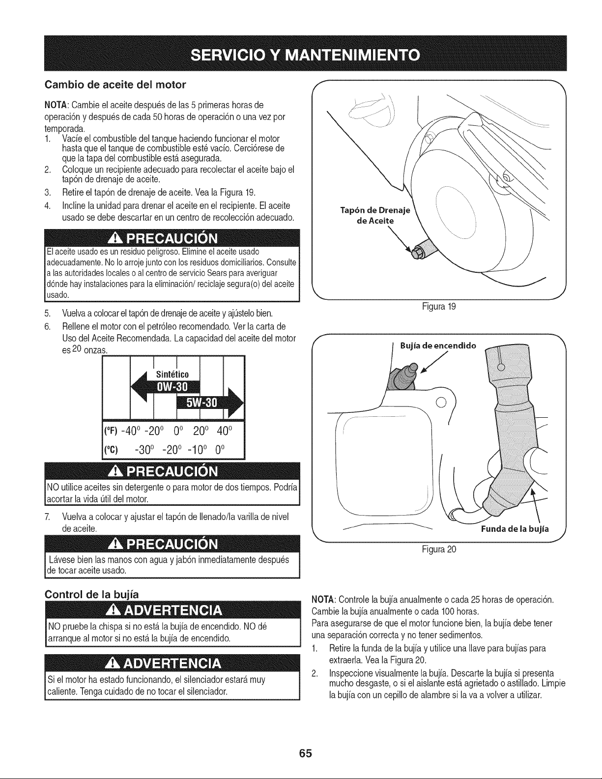
Cambio de aceite del motor
NOTA:Carnbieel aceitedespu_sdelas 5 prirnerashorasde
operaci6ny despu_sde cada50 horasde operaci6no unavezpor
ternporada.
1. Vacfeel combustibledel tanquehaciendofuncionarel motor
hastaqueel tanquedecombustibleest_vacfo.Cerci6resede
quela tapadelcombustibleest,.asegurada.
2. Coloqueun recipienteadecuadopara recolectarel aceitebajoel
tap6ndedrenajedeaceite.
3. Retireel tap6ndedrenajede aceite.Vea la Figura19.
4. Inclinela unidadparadrenarel aceite en el recipiente.Elaceite
usadose debedescartaren uncentrode recolecci6nadecuado.
Elaceiteusado es un residuo peligroso.Elimineel aceiteusado
adecuadamente.No Ioarroje juntocon los residuosdomicilMos. Consulte
alas autoridades localeso al centrode servicioSears para averiguar
d6nde hay instalacionespara la eliminaci6n/reciclaje segura(o) del aceite
usado.
.
6.
Vuelvaa colocarel tap6nde drenajedeaceitey ajOstelobien.
Relleneel motorcon el petr61eorecornendado.Verla carta de
UsodelAceite Recornendada.Lacapacidaddel aceitedel motor
es20 onzas.
("F)-40 ° -20° 0° 200 400
(oc) -300 -200 -100 0o
NOutiliceaceitessin detergenteo para motorde dostiernpos.Podrfa
acortarlavida Otildel motor.
7. Vuelvaa colocary ajustarel tap6nde Ilenado/lavarillade nivel
deaceite.
Tap6n de Drenaje
de Aceite
Figura19
j.- .........
// _ Funda de la bujia
Figura20
L_.vesebien las rnanoscon aguay jab6n inrnediatarnentedespu_s
detocaraceiteusado.
Control de la bujia
NO pruebelachispa si no est,. la bujfadeencendido.NOd_
arranqueal motorsi no est,.la bujfade encendido.
Si el motor haestadofuncionando,el silenciadorestar_,rnuy
caliente.Tengacuidadode notocar el silenciador.
NOTA:Controlela bujb anualrnenteo cada 25 horasdeoperaci6n.
Carnbiela bujb anualrnenteo cada 100horas.
Paraasegurarsede que el motorfuncionebien.la bujfadebetenet
unaseparaci6ncorrectay notenetsedirnentos.
1. Retirelafundade la bujb y utilice unaNavepara bujfaspara
extraerla.Vea la Figura20.
2. Inspeccionevisualrnentela bujfa. Descartela bujb si presenta
rnuchodesgaste,o siel aisianteest,.agrietadoo astillado.Lirnpie
labujb con uncepillode abrnbre si lava a volvera utilizar.
65
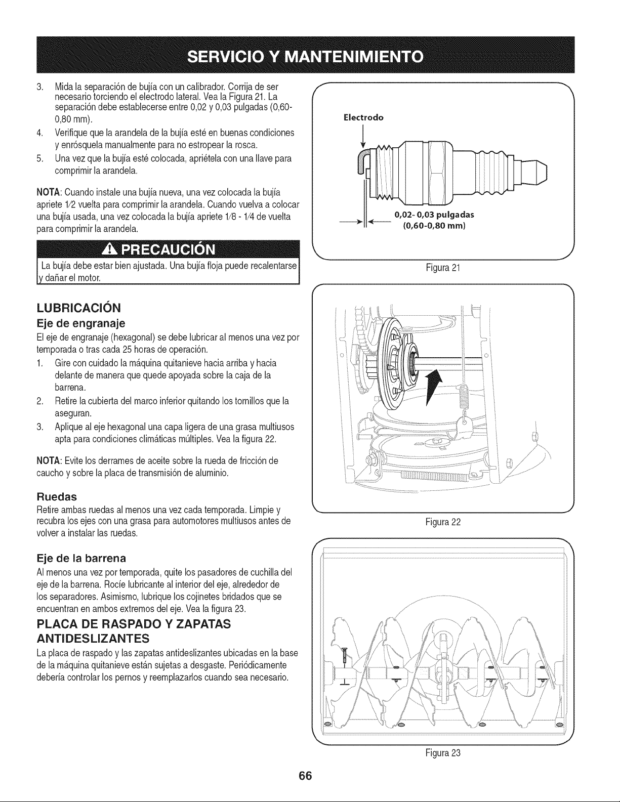
3. Midala separaci6ndebujia con un calibrador.Corrijade ser
necesariotorciendoel electrodolateral.Vea la Figura21. La
separaci6ndebeestablecerseentre0,02y 0,03 pulgadas(0,60-
0,80ram).
4. Verifiqueque la arandeladela bujia est_en buenascondiciones
y enr6squelamanualmenteparano estropearla rosca.
5. Unavezquela bujfaest_ colocada,apri_telacon una Ilavepara
comprimirla arandela.
NOTA:Cuandoinstaieuna bujianueva,unavezcolocadala bujia
apriete1/2vueltaparacomprimir[aarandela.Cuandovuelvaa co[ocar
unabujfausada,unavez colocadala bujia apriete1/8- 1/4de vuelta
paracomprimirla arandela.
da_arel motor.
f
Electrodo
0,02- 0,03 puigadas
{0,60-0,80 ram)
J
Figura21
LUBRICACION
Eje de engranaje
Eleje de engranaje(hexagonal)se debe lubricaral menosuna vez por
temporadaotras cada25 horasde operaci6n.
1. Gireconcuidadolam_.quinaquitanievehaciaarribay hacia
delantede maneraque quedeapoyadasobrela cajade la
barrena.
2. Retirela cubiertadelmarcoinferiorquitandolos tornillosquela
aseguran.
3. Apliquealeje hexagonalunacapaligeradeuna grasa multiusos
aptaparacondicionesclim_.ticasmOltiples.Vea lafigura22.
NOTA:Evitelos derramesdeaceitesobrela ruedadefricci6nde
cauchoy sobrela placade transmisi6nde aluminio.
Ruedas
Retireambasruedasal menosuna vezcada temporada.Limpiey
recubralos ejescon una grasapara automotoresmultiusosantesde
volvera instalarlas ruedas.
Eje de la barrena
AI menosunavez por temporada,quitelos pasadoresde cuchilladel
ejede la barrena.Rode lubricanteal interiordel eje,alrededorde
los separadores.Asimismo,lubriquelos cojinetesbridadosquese
encuentranen ambosextremosdel eje.Veala figura23.
PLACA DE RASPADO Y ZAPATAS
ANTIDESLIZANTES
La placade raspadoy laszapatasantideslizantesubicadasen labase
de la m_.quinaquitanieveest_.nsujetasa desgaste.Peri6dicamente
deberiacontrolarlos pernosy reemplazarloscuandosea necesario.
Figura22
Figura23
J
66
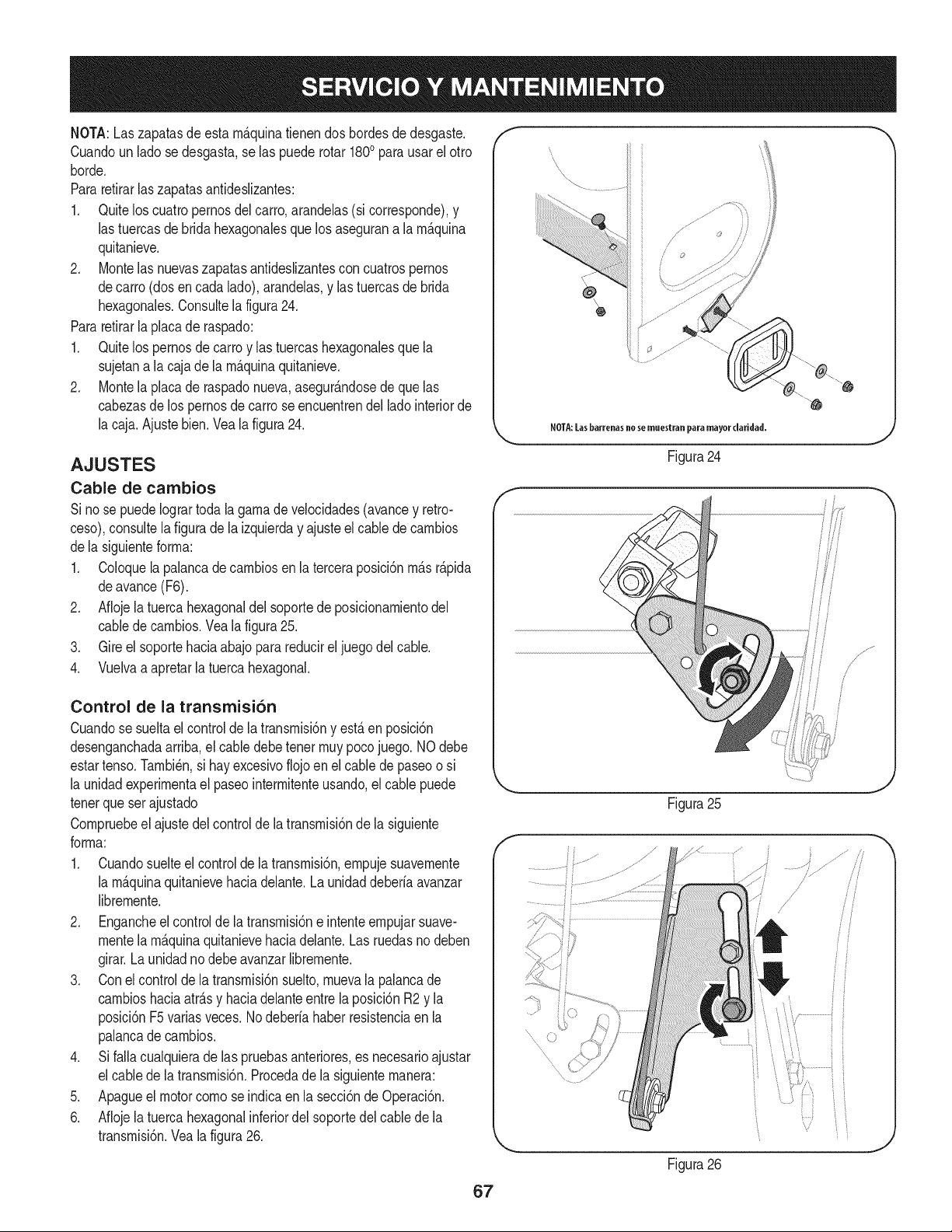
NOTA:Laszapatasdeesta rn_.quinatienendos bordesdedesgaste.
Cuandoun ladose desgasta,se las puede rotar 1800para usarel otro
horde.
Pararetirarlas zapatasantideslizantes:
1. Quitelos cuatropernosdel carro,arandelas(si corresponde),y
las tuercasde bridahexagonalesque losasegurana la rn_.quina
quitanieve.
2. Montelas nuevaszapatasantideslizantescon cuatrospernos
decarro (dosencada lado),arandelas,y las tuercasde brida
hexagonales.Consultela figura24.
Pararetirarla placade raspado:
1. Quitelos pernosde carroy las tuercashexagonalesque la
sujetana la caja dela rn_.quinaquitanieve.
2. Montela placade raspadonueva,asegur_.ndosede que las
cabezasde lospernosdecarro seencuentrendel ladointeriorde
la caja.Ajuste bien.Veala figura24.
AJUSTES
Cable de cambios
Si no se puedeIogrartodala garnade velocidades(avancey retro-
ceso),consultela figuradela izquierday ajusteel cablede carnbios
dela siguienteforrna:
1. Coloquela palancade carnbiosenla terceraposici6nrn_.sr_.pida
deavance(F6).
2. Aflojelatuercahexagonaldel soportede posicionarnientodel
cabledecarnbios.Vea lafigura25.
3. Gireel soportehaciaabajoparareducirel juegodel cable.
4. Vuelvaa apretarla tuercahexagonal.
Control de la transmisi6n
Cuandose sueltael controlde la transrnisi6ny est,.en posici6n
desenganchadaarriba,el cabledebetenor rnuypocojuego. NOdebe
estartenso.Tarnbi_n,si hay excesivoflojoen el cable de paseoo si
la unidadexperirnentael paseointerrnitenteusando,elcable puede
tenorqueser ajustado
Cornpruebeel ajustedel controlde la transrnisi6nde la siguiente
forrna:
1. Cuandosuelteel controlde la transrnisi6n,ernpujesuavernente
la rn_.quinaquitanievehaciadelante.Launidaddeberia avanzar
librernente.
2. Engancheel controlde latransrnisi6ne intenteernpujarsuave-
montela rn_.quinaquitanievehaciadelante.Las ruedasno deben
girar.Launidadnodebe avanzarlibrernente.
3. Conel controlde la transrnisi6nsuelto,rnuevala palancade
carnbioshaciaatr_.sy haciadelanteentre laposici6nR2 y la
posici6nF5variasveces.Nodeberiahaberresistenciaen la
palancade carnbios.
4. Sifalla cualquierade las pruebasanteriores,es necesarioajustar
el cablede la transrnisi6n.Procedade la siguienternanera:
5. Apagueelmotorcornose indicaen la secci6nde Operaci6n.
6. Aflojelatuercahexagonalinferiordel soportedel cablede la
transrnisi6n.Veala figura26.
f
NOTA:[as barrenas no se muestran para mayor daridad.
Figura24
i
Figura25
Figura26
67
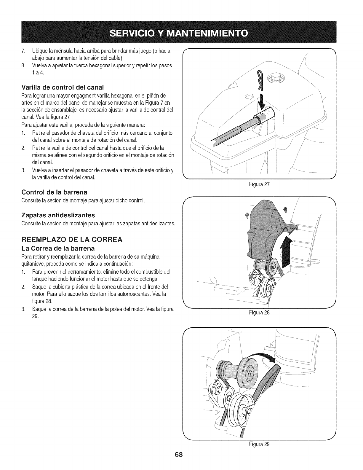
7. Ubiquelarn_nsulahaciaarribaparabrindarrn_.sjuego (ohacia
abajoparaaurnentarla tensi6ndel cable).
8. Vuelvaa apretarla tuercahexagonalsuperiory repetirlos pasos
la4.
Varilla de control del canal
ParaIograrunamayorengagrnentvarillahexagonalen el pi56nde
artesenel marcodelpanelde rnanejarse rnuestraen la Figura7 en
la secci6ndeensarnblaje,es necesarioajustar la varillade control del
canal.Veala figura27.
Paraajustarestevarilla,procedade la siguienternanera:
1. Retireel pasadorde chavetadel orificio rn_.scercanoal conjunto
delcanal sobreel rnontajede rotaci6ndelcanal.
2. Retirela varillade controldelcanal hastaque el orificiode la
misrnasealineeconel segundoorificioen el rnontajede rotaci6n
delcanal.
3. Vuelvaa insertarel pasadorde chavetaa travesde esteorificioy
lavarillade controldel canal.
Control de la barrena
Consultela seciondernontajeparaajustardichocontrol.
Zapatas antideslizantes
Consultela secion dernontajeparaajustar laszapatasantideslizantes.
REENIPLAZO DE LA CORREA
La Correa de la barrena
Pararetirary reernplazarla correade la barrenade su rn_.quina
quitanieve,procedacornose indicaacontinuaci6n:
1. Paraprevenirel derramarniento,elirninetodo elcombustibledel
tanquehaciendofuncionarel motorhastaquese detenga.
2. Saquela cubiertapl_.sticade lacorreaubicadaen el frentedel
motor.Paraello saquelos dos tornillosautorroscantes.Veala
figura28.
3. Saquela correade la barrenade la poleadel motor.Vea lafigura
29.
/
/
/)
?..... /
/
Figura27
J J
Figura 28
Figura29
68
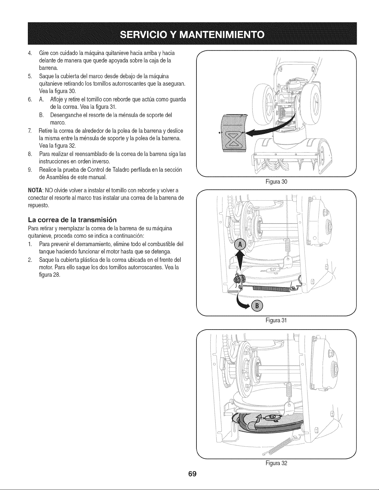
4. Gireconcuidadola m_.quinaquitanievehaciaarribay hacia
delantede maneraque quedeapoyadasobrela cajade la
barrena.
5. Saquela cubiertadelmarcodesdedebajode la m_.quina
quitanieveretirandolostornillosautorroscantesquela aseguran.
Veala figura30.
6. A. Aflojey retireel tornillocon rebordequeactQacomoguarda
dela correa.Vealafigura31.
B. Desengancheel resortede la m_nsuladesoportedel
marco.
7. Retirelacorreadealrededorde la poleade la barrenay deslice
la mismaentre lam_nsulade soportey la polea de la barrena.
Vealafigura32.
8. Pararealizarel reensambladode la correade labarrenasiga las
instruccionesen orden inverso.
9. Realicela pruebadeControlde Taladroperfiladaen lasecci6n
deAsambleadeeste manual.
NOTA:NOolvidevolvera instalarel tornillocon rebordey volvera
conectarel resorteal marcotras instalarunacorreade la barrenade
repuesto.
La correa de la transrnisi6n
Pararetirary reemplazarla correadela barrenade su m_.quina
quitanieve,procedacomose indicaa continuaci6n:
1. Paraprevenirel derramamiento,eliminetodoel combustibledel
tanquehaciendofuncionarel motorhastaque sedetenga.
2. Saquela cubiertapl_.sticade lacorreaubicadaen el frentedel
motor.Paraello saquelosdos tornillosautorroscantes.Veala
figura28.
J
Figura30
F
Figura31
,J
69
Figura32
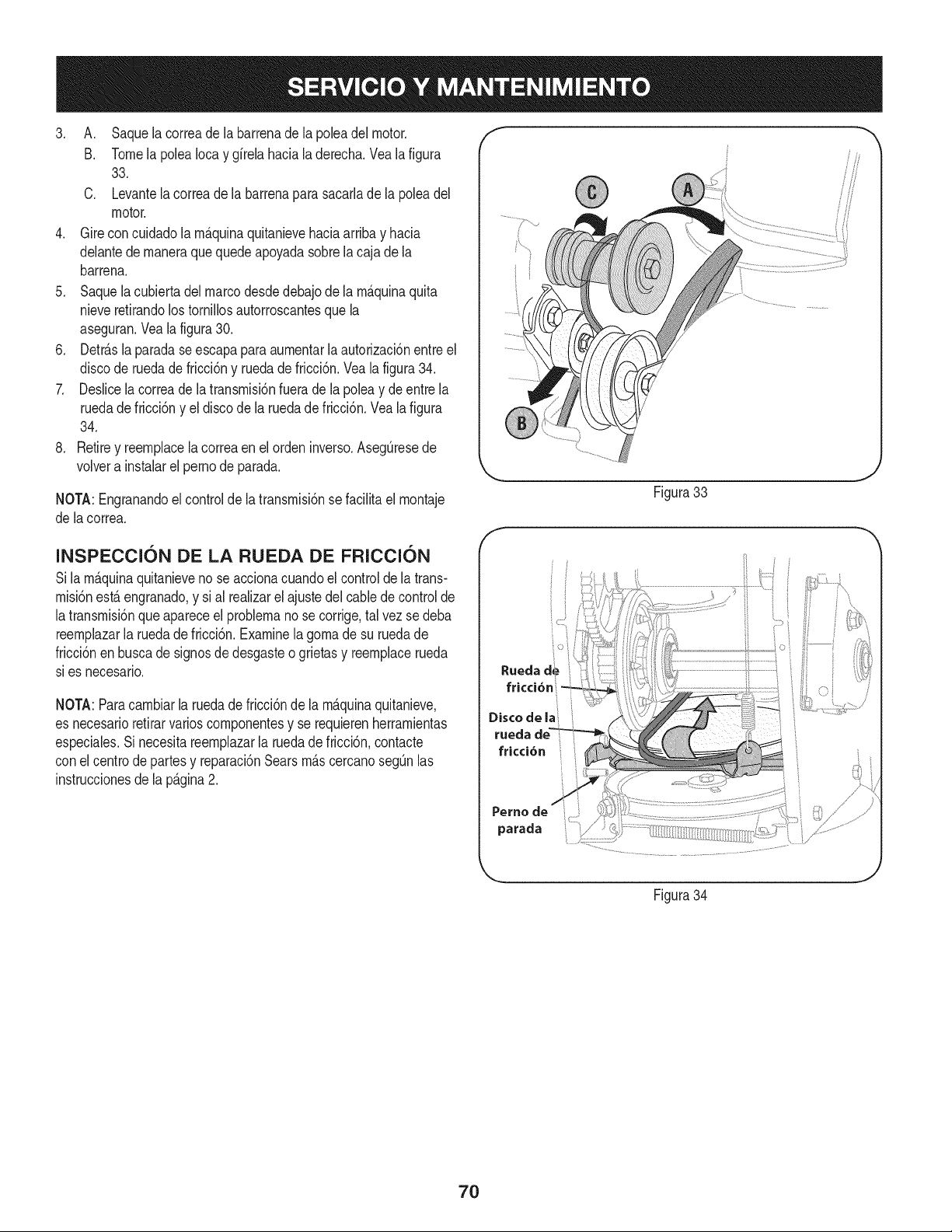
3. A. Saquelacorreadelabarrenadelapoleadelmotor.
B. TomelapoleaIocaygirelahacialaderecha.Vealafigura
33.
C. Levantelacorreadelabarrenaparasacarladelapoleadel
motor.
4. Gireconcuidadolam_.quinaquitanievehaciaarribayhacia
delantedemaneraquequedeapoyadasobrelacajadela
barrena.
5. Saquelacubiertadelmarcodesdedebajodelam_.quinaquita
nieveretirandolostornillosautorroscantesquela
aseguran.Vealafigura30.
6. Detr_.slaparadaseescapaparaaumentarlaautorizaci6nentreel
discoderuedadefricci6nyruedadefricci6n.Vealafigura34.
7. Deslicelacorreadelatransmisi6nfueradelapoleaydeentrela
ruedadefricci6nyeldiscodelaruedadefricci6n.Vealafigura
34.
8. Retireyreemplacelacorreaenelordeninverso.AsegQresede
volverainstalarelpernodeparada.
NOTA:Engranandoelcontroldelatransmisi6nsefacilitaelmontaje
delacorrea.
INSPECCI6N DE LA RUEDA DE FRICCI6N
Sila m_.quinaquitanieveno se accionacuandoel controlde latrans-
misi6nest,.engranado,y si al realizarel ajustedelcablede controlde
latransmisi6nqueapareceel problemanose corrige,tal vezsedeba
reemplazarla ruedade fricci6n.Examinela gomade su ruedade
fricci6nen buscade signosdedesgasteo grietasy reemplacerueda
sies necesario.
NOTA:Paracambiarla ruedade fricci6nde la m_.quinaquitanieve,
es necesarioretirarvarioscomponentesy se requierenherramientas
especiales.Si necesitareemplazarla ruedadefricci6n,contacte
con el centrode partesy reparaci6nSearsm_.scercanosegQnlas
instruccionesde la p_.gina2.
f
Figura33
J
F
oi
Rueda de
fricci6n
Disco de la
ruecla
fricci6n
Perno
parada
Figura34
7O
Sinosevaa utilizael equipodurante30 dfaso rn_.s,o sies el finaldela ternporadadenievey ya noexisteposibilidaddequenieve,es necesario
alrnacenarel equipode rnaneraadecuada.Sigalasinstruccionesde alrnacenarnientoquese indicana continuaci6nparagarantizarelrendirniento
rn_.xirnodela rn_.quinaquitanieveduranternuchosa_os.
PREPARACI6N DEL MOTOR
Losrnotoresquese alrnacenandurantern&sde30 dfas necesitan
serdrenadosde combustiblepara evitarquese deterioreny se forrne
gornaenel sisternade combustibleoen las piezasprincipalesdel
carburador.Si la gasoNnade su motorse deterioraduranteel alrnace-
narniento,es posibleque deba repararo reernplazarelcarburadory
otroscornponentesdel sisternade combustible.
1. Elirninetodoel combustibledel tanquehaciendofuncionarel
motorhastaquese detenga.No intentede combustibleparael
motor.
2. Carnbieel aceitedel motor.
3. Extraigala bujfade encendidoy viertaen elcilindroaproxirna-
darnente1 onza(30 rnl)de aceiteparamotorNrnpio.Tire varias
vecesdel arrancadorde retrocesopara distribuirel aceite y
reinstalela bujfa.
4. Lirnpielos residuosde alrededordel motor,y debajo,alrededor,
y detr_.sdel silenciador.ApNqueunacapa delgadade aceiteen
todaslas _.reasquepuedenNegara oxidarse.
• Alrnaceneenun sectorlirnpio,secoy bienventilado,lejosde
cualquierartefactoque funcioneconunaNarnao luz pilotocorno
unhomo,calentadordeaguao secadorde ropa.Evitecualquier
sectorcon un motorel_ctricoque produzcachispaso dondese
utilicenherrarnientasel_ctricas.
Nuncaalrnacenela rn_.quinaquitanieveconcombustibleenel
tanqueenun espaciocerradooen _.reascon pocaventilaci6n,
dondelosgasesdel combustiblepuedanalcanzarel fuego,chispas
o una luz pilotocornola quetienenalgunoshornos,calentadoresde
agua,secadoresde ropao algQnotto dispositivoagas.
PREPARACI6N DE LA NIAQUINA QUITANIEVE
1. Cuandoalrnacenelarn&quinaquitanieveen ungalp6nde
dep6sitornet_.licoo con pocaventilaci6n,tengaespecialcuidado
de realizarleuntratarnientoanti- oxidanteal equipo.Useaceite
ligeroo silic6npararecubrirel equipo,especialrnentelas
cadenas,los resortes,loscojinetesy loscables.
2. Elirninetodo el polvodelexteriordel motory del equipo.
3. Sigalas recornendacionesde lubricaci6nen la secci6nde
rnantenirnientodeeste manual.
4. AIrnaceneel equipoen un _.readespejaday seca.
5. Inflarlos neurn_.ticosa la presi6nde psi rn_.xirna.Consulteel
costadodelneurn_.tico.
• Si es posible,evite sectoresde alrnacenarnientocon rnucha
hurnedad.
• Mantengael motorniveladoen el alrnac_n.Lainclinaci6ndel
motorpuedecausarperdidasde combustibleo aceite.
71
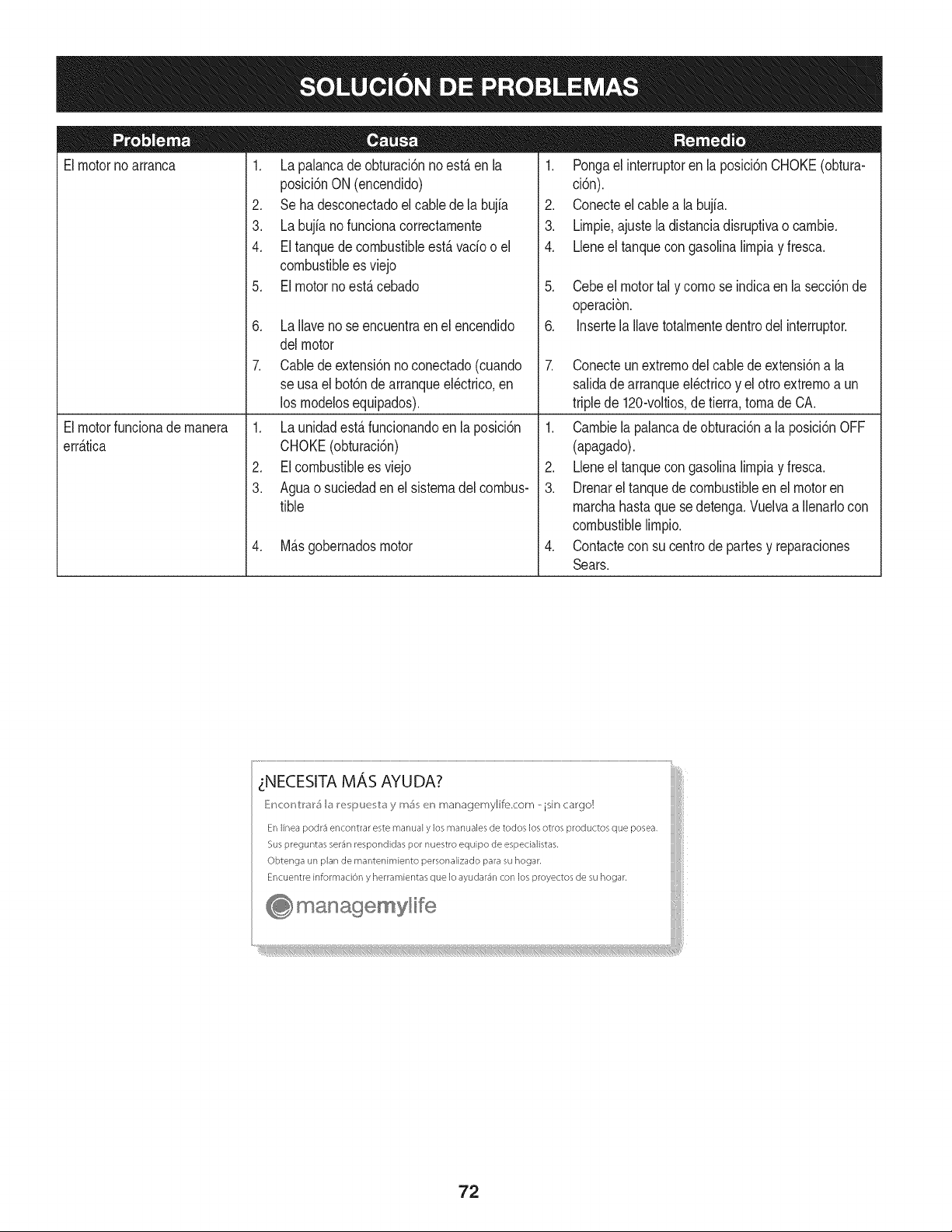
Elmotornoarranca
1. La palancade obturaci6nnoest,.enla
posici6nON (encendido)
2. Seha desconectadoel cablede la bujia
3. La bujianofunciona correctamente
4. Eltanquedecombustibleest,.vado o el
combustibleesviejo
5. El motornoest,. cebado
6. La Ilavenose encuentraen el encendido
delmotor
7. Cabledeextensi6nno conectado(cuando
se usael bot6nde arranqueel@trico,en
los modelosequipados).
1. Pongael interruptoren la posici6nCHOKE(obtura-
ci6n).
2. Conecteel cablea la bujfa.
3. Limpie,ajustela distanciadisruptivao cambie.
4. Lleneel tanquecongasolinalimpiay fresca.
5. Cebeel motortal y comose indicaen la secci6nde
operaci6n.
6. Insertela Ilavetotalmentedentrodel interruptor.
7. Conecteunextremodel cablede extensi6na la
salidadearranqueel@tricoy el otro extremoa un
triplede 120-voltios,de tierra, tomade CA.
Elmotorfuncionademanera
err_.tica
1. La unidadest,.funcionandoen laposici6n
CHOKE(obturaci6n)
2. EIcombustibleesviejo
3. Aguao suciedadenel sistemadel combus-
tible
4. M_.sgobernadosmotor
1. Cambiela palancade obturaci6na la posici6nOFF
(apagado).
2. Lbne el tanquecongasolinalimpiay fresca.
3. Drenarel tanquede combustibleenel motoren
marchahastaque sedetenga.Vuelvaa Ilenarlocon
combustiblelimpio.
4. Contactecon su centrode partesy reparaciones
Sears.
zNECESITA MAS AYUDA?
_!ncor_V:r_r5 b I_e i_uu v:_y m_ en managemylife.com _ isin cargo!
En linea podr3 encontrar este manual y los manuales de todos los otros productos que posea,
Sus preguntas ser_n respondidas pot nuestro equipo de especialistas,
Obtenga un plan de rnantenimiento personalizado para su hogar,
Encuentre informaciOn y herramientas que Io ayudar_n con los proyectos de su hogar,
managemyHfe
72
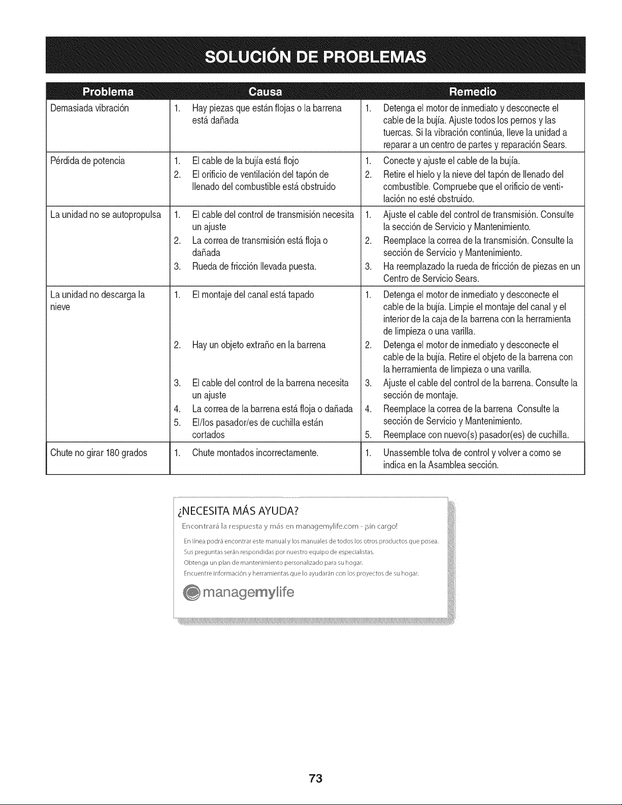
Dernasiadavibraci6n
1. Haypiezasqueest_.nfiojaso la barrena
est,.dafiada
1. Elcable dela bujfaest,.flojo
2. Elorificiodeventilaci6ndel tap6nde
Ilenadodel combustibleest,.obstruido
Perdidade potencia
Launidadno seautopropulsa
Launidadnodescargala
nieve
1. Elcable delcontrolde transrnisi6nnecesita
unajuste
2. Lacorreade transrnisi6nest,.floja o
da_ada
3. Ruedadefricci6nIlevadapuesta.
1. Elrnontajedel canalest,.tapado
2. Hayunobjetoextra_oenla barrena
3. Elcable delcontrolde la barrenanecesita
unajuste
4. Lacorreade la barrenaest,. flojao da_ada
5. El/lospasador/esde cuchillaest_.n
cortados
1. Detengael motorde inrnediatoy desconecteel
cablede la bujia.Ajuste todoslos pernosy las
tuercas.Sila vibraci6ncontinQa.Ilevela unidada
reparara un centrode partesy reparaci6nSears.
1. Conectey ajusteel cablede la bujfa.
2. Retireel hieloy la nievedel tap6nde Ilenadodel
combustible.Cornpruebequeel orificiode venti-
laci6nnoest_obstruido.
1. Ajusteel cabledel controlde transrnisi6n.Consulte
la secci6nde Servicioy Mantenirniento.
2. Reernplacela correade latransrnisi6n.Consultela
secci6nde Servicioy Mantenirniento.
3. Ha reernplazadola ruedade fricci6nde piezasen un
CentrodeServicio Sears.
1. Detengael motorde inrnediatoy desconecteel
cablede la bujia.Lirnpieel rnontajedelcanaly el
interiorde la cajade labarrenacon laherrarnienta
de lirnpiezao una varilla.
2. Detengael motorde inrnediatoy desconecteel
cablede la bujia.Retireelobjetode la barrenacon
la herrarnientade lirnpiezao una varilla.
3. Ajusteel cabledelcontrolde la barrena.Consultela
secci6nde rnontaje.
4. Reernplacela correade la barrena Consultela
secci6nde Servicioy Mantenirniento.
5. Reernplacecon nuevo(s)pasador(es)de cuchilla.
Chuteno girar 180grados 1. Chuternontadosincorrectarnente. 1. Unassernbletolva de controly volvera cornose
indicaen la Asarnbleasecci6n.
73
MTD CONSUMER GROUP, iNC. (MTD), el Bordo de Recursos de Aire de California (CARB)
y la Agencia de Protecci6n Medioambiental de Estados Unidos (U. S. EPA)
Declaraci6n de Garantia del Sistema de Control de Emisiones
(Derechos y obligaciones del propietario seg_n la garantia contra defectos)
LACOBERTURADESISTEMADECONTROLDEEMISIONESAPLICABLEA MOTORESCERTIFICADOSCOMPRADOSENCALIFORNIA
EN2005Y A PARTIRDE ENTONCES,QUESON USADOSEN CALIFORNIA,Y HASTAANO2005DE MODELOCERTIFICADOY MOTORES
POSTERIORESQUESON COMPRADOSY USADOSENOTRAPARTEEN LOSESTADOSUNIDOS.
Californiayen otraparteen la Coberturade Garantiade Defectosde Controlde Emisi6nde los EstadosUnidos
El Bordode Recursosde Aire de California(CARB),la U.S. EPAy MTDsecomplacenen explicarla garantiadel sistemade controldeemisiones
de su motorparaequipotodo terreno,modelo,aSo2005y versionesposteriores.En California,los nuevosmotorespequeSosparaequipotodo
terrenose debendise5ar,fabricary equiparparacumplirconest_.ndaresde antinieblat6xicade estados.Enotraparteen los EstadosUnidos,
el nuevonocamino,motoresdeignici6ndechispacertificadospara elmodelo2005y m_.starde,debe encontrarel juego de est_.ndaressimilar
adelantepor los EstadosUnidos.EPA.MTDdebegarantizarel sistemade controlde emisionesde su motorpor elperiodode tiempoindicadom&s
abajo,siemprey cuandono hayaexistidousoincorrecto,negligenciani mantenimientoinadecuadode su motorpequeBoparaequipotodoterreno.
El sistemade controlde emisionespuedeincluirpiezascomo,por ejemplo,el carburador,sistemadeinyecci6ndecombustible,el sistemade
encendido,el catalizador,losdep6sitosdecombustible,abastecede combustiblelineas, gorrasde combustible,v&lvulas,latas,filtros,mangueras
devapor,abrazaderas,conectoresy otroscomponentesrelacionadosconlas emisiones.
Dondeexistauna condici6ncubiertaporla garantia,MTDreparar&su motor pequeBopara equipotodoterrenosincostoalguno incluyendoel
diagn6stico,laspiezasy la manode obra.
COBERTURA DE LA GARANTJA DEL FABRICANTE:
Estesistemade controldeemisionesse garantizapor el t@rminodedos a5os.Si algunapiezade su motorrelacionadacon lasemisioneses
defectuosa,MTD reparar&o sustituir&dichapieza.
RESPONSABJLIDADES DEL PROPIETARIO SEGUN LA GARANTJA:
Comopropietariode un motorpequeSode equipotodoterreno,ustedes responsablede realizarel mantenimientonecesarioquefigura en el
manualdel propietario.MTDle recomiendaque conservetodoslos recibosque cubrenlos serviciosde mantenimientodel motorpeque5opara
equipotodoterreno,noobstanteIo cual MTDnopodr&denegarel cumplimientode la garantiaQnicamentepor la faltade reciboso porsu imposibi-
lidadde asegurarquese realizar_.ntodos los serviciosde mantenimientoprogramado.
Comopropietariodel motorpeque5oparaequipotodo terreno,sinembargo,ustedtambi@ndebesaberque MTDpuede denegarla coberturadela
garantiasi su motorpeque5opara equipotodoterrenoo una piezadel mismofallandebidoa usoincorrecto,negligencia,mantenimientoindebido
oa modificacionesno aprobadas.
Ustedes responsablede presentarla cortadoradecespedal centrode distribuci6no de mantenimientode MTDCONSUMERGROUP,INC. tan
prontocomo aparecierael problem& Lasreparacionescubiertaspor lagarantfasedebenIlevaracabo enun lapsorazonableque noexcedade
30dias.Si desearealizaralgunaconsultacon respectoa la coberturade lagarantia,debeponerseencontactocon su distribuidorlocalde MTD.
Paracomunicarseconla Linea deAsistenciaal Clientede Distribuidoresde MTD,Ilameal nQmero(877)282-8684.
REQUERJMJENTOS DE GARANTJA SOBRE DEFECTOS PARA MOTORES PEQUENOS DE EQUJPO TODO TERRENO
DE 1995YVERSJONES POSTERJORES:
Estasecci6nse aplicaa motorespeque5osdeequipotodo terrenode 1995y versionesposteriores.Elperiodode garantiacomienzaa partirde la
fechaen que el motoro elequiposeentreganal compradorfinal.
(a)Coberturade la garantiacontraemisionesgenerales
MTDgarantizaal compradorfinaly a cada compradorsubsiguientequeel motor:
(1)hasido diseSado,construidoy equipadode maneraquecumplacontodaslas regulacionesvigentesadoptadasporel Departamentode los
RecursosdeAire en virtuda suautoridadconferidaen los capitulos1 y 2, Parte5, Divisi6n26 del C6digode Saludy Seguridad;y
(2)est,. librede defectosen los materialesy en la manode obraque causenla falla de unapiezabajogarantiaque seaid@nticaen todos los
aspectosmaterialesa lapiezacomoaparecedescriptaen laaplicaci6ndelfabricantedel motorparacertificaci6npor unperiodode dos a5os.
Lb/Lagarantiasobre piezasrelacJonadasconemisJonesse interpretar_,de la sJguientemanera:
(1)Cualquierpiezacubierta por garantiaque no est@programadapara su reemplazosegQnel mantenimientorequeridoen las instrucciones
escritasdela Subsecci6n(c) debeestar garantizadapor unperiodode garantiadefinidoen la Subsecci6n(a) (2). Si la piezafalladurante
el periodode coberturadela garantia,la mismaser_.reparadao reemplazadaporMTD de acuerdocon laSubsecci6n(4)a continuaci6n.
Cualquierpiezareparadao reemplazadasegQnla garantiasegarantizarB,porel restodelperiodode garantia.
(2) Cualquierpiezacubiertaporgarantiaque est@programadasoloparainspecci6nregularen las instruccionesescritasde la Subsecci6n
(c) debeestargarantizadaporun periododegarantiadefinidoen la Subsecci6n(a) (2). Unadeclaraci6nen dichasinstruccionesporescrito
alefectode "reparaci6no reemplazosegQnseanecesario"no reducir_,elperiodode coberturade la garantia.Cualquierpiezareparadao
reemplazadasegQnla garantiase garantizar_,porel restodel periodode garantia.
(3) Cualquierpiezagarantizadaqueest_prograrnadaparareernplazosegQnelrnantenirnientorequeridodeconforrnidadconlasinstruc-
clonesescritasdelaSubsecci6n(c)segarantizaporelperiododetiernpoanterioralaprirnerafechadereernplazoprograrnadaparaesa
pieza.Silapiezafallaantesdelprimerreernplazoprogramatic,larnisrnaser_.reparadaoreernplazadaporMTDdeacuerdoconlaSubsecci6n
(4)acontinuaci6n.Cualquierpiezareparadaoreernplazadabajogaranfiasegarantizar_,porelrestodelperiodoanterioralprimerreernplazo
programaticpuntualparaesapieza.
(4)Lareparaci6noelreernplazodecualquierpiezagarantizadadeconforrnidadconlasdisposicionesdelagaranfiaqueaquiseestipulase
deberealizarenuncentrodegaranfiasincostoalgunoparaelpropietario.
(5)SinperjuiciodelasdisposicionesdelaSubsecci6n(4)anterior,losserviciosoreparacionescubiertosporlagaranfiadebensersurnin-
istradosportodosloscentrosdedistribuci6ndeMTDquetenganlafranquiciapararealizarreparacionesyrnantenirnientoalosrnotoresen
cuesti6n.
(6)ElpropietarionodebeafrontarningQncargoparatrabajosdediagn6sticoqueIlevenalaconclusi6ndequeunapiezabajogaranfiapresenta
efectivarnentedefectos,siernpreycuandodichodiagn6sticoseaIlevadoacaboenuncentrocubiertoporlagarantia.
(7)ElfabricantedelmotoresresponsablepordaSoscausadosaotroscornponentesdernotoresderivadosdelafallabajogaranfiadecualquier
piezagarantizada.
(8)DurantetodoelperiododegaranfiadelmotordefinidoenlaSubsecci6n(a)(2),MTDrnantendr_,unsurninistrodepiezascubiertaspor
garantiasuficienteparasatisfacerladernandaesperadaparatalespiezas.
(9)Cualquierpiezadereernplazosepodr_,usarparaelcurnplirnientodelrnantenirnientooreparacionesbajogaranfia,ysesurninistrar_,sin
cargoalpropietario.Dichousonoreducir_,lasobligacionesdegarantiadeMTD.
(10)Nosepodr_.nusarpiezasadicionalesnirnodificadasquenoest_nexentasdeacuerdoconelDepartarnentodelosRecursosdelAire(Air
ResourcesBoard).Elusodepiezasadicionalesornodificadasnoexentasser_.causasuficienteparaanularunreclarnobajogaranfiarealizado
deacuerdoconestearticulo.Elfabricantedelmotornotendr_,responsabilidad,enconforrnidadconestearticulo,degarantizarfallasdepiezas
garantizadasquefuerencausadasporelusodeunapiezanoexentaadicionalornodificada.
.(c)MTDincluir_,unacopiade la siguientelistade piezasbajo garantiacontraernisionescon cadanuevomotor,utilizandolas partesde la lista
a_plicablesal motor.
(1)Sisternadernedici6ndecombustible
• Sisternade rnejorapara inicioen frio (cebadosuave)
• Carburadory cornponentesinternos
• Bornbade combustible
• Dep6sitode combustible
(2) Sisternade inducci6ndeaire
• Filtrode aire
• Colectorde entrada
(3) Sisternade encendido
• Bujia(s)
• Sisternadeencendidopor magneto
(4)Sisternadeescape
• Catalizador
• SAI (v_Jvulade CaSa)
(5) Cornponentesvariosutilizadosen el sisternaanterior
• V_Jvulase interruptoresde vado, ternperatura,posici6nsensiblesal tiernpo
• Conectoresy rnontajes
(6)Controlde Evaporative
• Manguerade CombustiblecertificadaparaARB evaporativeernisi6nde 2006.
• Abrazaderasde Manguerade Combustible
• Gorrade combustibleatada
• Latade carb6n
• Lineasdevapor
GD0C-100174Rev.B
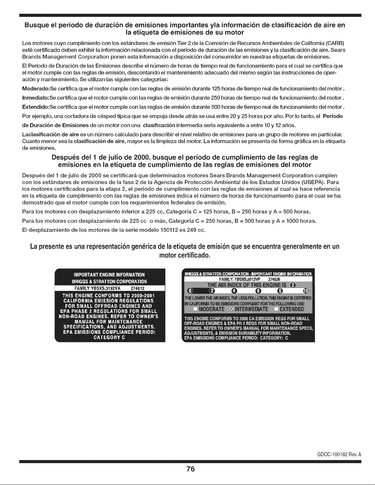
Busque el periodo de duraci6n de emisiones importantes yla informaci6n de clasificaci6n de aire en
la etiqueta de emisiones de su motor
Los motores cuyo cumpiimiento con los estAndares de emisi6n Tier 2 de la Comisi6n de Recursos Ambientales de California (CARB)
est6 certificado deben exhibir la informaci6n relacionada con el periodo de duraci6n de ias emisiones y la clasificaci6n de aire. Sears
Brands Management Corporation ponen esta informaci6n a disposici6n del consumidor en nuestras etiquetas de emisiones.
Ei Periodo de Duraci6n de las Emisiones describe el nQmero de horas de tiempo real de funcionamiento para el cuai se certifica que
el motor cumpie con ias reglas de emisi6n, descontando el mantenimiento adecuado del mismo segQn las instrucciones de oper-
aci6n y mantenimiento. Se utilizan las siguientes categonas:
Moderado:Se certifica que el motor cumpie con las reglas de emisi6n durante 125 horas de tiempo real de funcionamiento del motor.
Inmediato:Se certifica que el motor cumpie con las reglas de emisi6n durante 250 horas de tiempo real de funcionamiento del motor.
Extendido:Se certifica que el motor cumpie con las reglas de emisi6n durante 500 horas de tiempo real de funcionamiento del motor.
Por ejemplo, una cortadora de c6sped tJpica que se empuja desde arras se usa entre 20 y 25 horas por aSo. Por Io tanto, el Periodo
de Duraci6n de Emisiones de un motor con una clasificaci6n intermedia sena equivaiente a entre 10 y 12 aSos.
Laciasificaci6n de aire es un nQmero calculado para describir el nivel relativo de emisiones para un grupo de motores en particular.
Cuanto menor sea la clasificaci6n de aire, mayor es la limpieza del motor. La informaci6n se presenta de forma grAfica en la etiqueta
de emisiones.
Despu_s del 1 de julio de 2000, busque el periodo de cumplimiento de las reglas de
emisiones en la etiqueta de cumplimiento de las reglas de emisiones del motor
Despu6s del 1 de julio de 2000 se certificarA que determinados motores Sears Brands Management Corporation cumplen
con los estAndares de emisiones de la fase 2 de la Agencia de Protecci6n Ambientai de los Estados Unidos (USEPA). Para
los motores certificados para la etapa 2, el periodo de cumplimiento con ias reglas de emisiones al cual se hace referencia
en la etiqueta de cumplimiento con las reglas de emisiones indica el nQmero de horas de funcionamiento para el cual se ha
demostrado que el motor cumple con los requerimientos federales de emisi6n.
Para los motores con desplazamiento inferior a 225 cc, Categoria C = 125 horas, B = 250 horas y A = 500 horas.
Para los motores con desplazamiento de 225 cc o mAs, Categoria C = 250 horas, B = 500 horas y A = 1000 horas.
El desplazamiento de los motores de la serie modelo 150112 es 249 cc.
La presente es una representaci6n gen_rica de la etiqueta de emisi6n que se encuentra generaimente en un
motor certificado.
FAMILYYBSXS.3192VA 274812
GDOC-100182Rev.A
76
Felicitaciones por haber realizado una adquisici6n inteligente. El producto Craftsman® que ha
adquirido esta diseSado y fabricado para brindar muchos aSos de funcionamiento confiable. Pero
como todos los productos a veces puede requerir de reparaciones. Es en ese momento cuando el
disponer de un Acuerdo de protecci6n para reparaciones le puede ahorrar dinero y problemas.
A continuaci6n se detallan los puntos incluidos en el Acuerdo:
[] Servicio experto prestadopor nuestros 10,000 especialistas en reparaciones profesionales
[] Servicio ilirnitado sin cargo para las piezasy la mano de obra en todas las reparacionescubiertas
[] Reernplazo del producto hasta 1500 d61aressi no es posible reparar el producto cubierto
[] Descuento de 25% del precio normal del servicio y de las piezas relacionadas con el mismo que no esten cubiertas
por el acuerdo; ademas, 25% del precio normal de la verificaci6n de mantenimientopreventivo
[] Ayuda r_pida pot tel_fono - Io IlamamosResoluci6n RApida- el apoyo telef6nico de un Chamusca al representante.
Piense en nosotros como el manual "de un dueSohablador."
Una vez adquirido el Acuerdo, puede programar el servicio con tan s61orealizar una Ilamadatelef6nica. Puede Ilamar en
cualquier momentodel dia o de la noche o programar un servicio en linea.
ElAcuerdo de Protecci6nde Reparaci6nes una compra sin riesgo. Si usted anula por alguna raz6n duranteel periodo de
garantia de producto, proporcionaremos un reembolso Ileno.O, un reembolsoprorrateado en cualquier momentodespues
del periodo de garantia de producto expira, iAdquiera hoy su acuerdode protecci6n para reparaciones!
Se aplican determinadas limitaciones y exclusiones. Para obtener informaciTn adicional y precios en los Estados
Unidos Ilame al 1-800-827-6655.
El *Coverage en Canad_ivaria en algunos articulos. Para detalles Ilenos la Ilamada Chamusca Canad_ien 1-800-
361-8885.
Servicio de instalaci6n de Sears
Si desea solicitar la instalaci6n profesionalde Sears de aparatos domesticos, dispositivos paraabrir portones, calentado-
res de agua y otros articulos domesticos importantes, en los Estados Unidos o Canada flame al 1-800-4-MY-HOME®.
77

78

79

Your Home
For troubleshooting, product manuals and expert advice:
managernylife
www.managemylife.com
For repair - in your home - of all major brand appliances,
lawn and garden equipment, or heating and cooling systems,
no matter who made it, no matter who sold it!
For the replacement parts, accessories and
owner's manuals that you need to do-it-yourself.
For Sears professional installation of home appliances
and items like garage door openers and water heaters.
1-800-4-MY-HOME ® (1-800-469-4663)
Call anytime, day or night (U.S.A. and Canada)
www.sears.com www.sears.ca
Our Home
For repair of carry-in items like vacuums, lawn equipment,
and electronics, call anytime for the location of your nearest
Sears Parts & Repair Service Center
1-800-488-1222 (U.S.A.) 1-800-469-4663 (Canada)
www.sears.com www.sears.ca
To purchase a protection agreement on a product serviced by Sears:
1-800-827-6655 (U.S.A.) 1-800-361-6665 (Canada)
Para pedir servicio de reparaci6n
a domicilio, y para ordenar piezas:
1-888-SU-HOGAR ®
(1-888-784-6427)
www.sears.com
Au Canada pour service en frangais:
1-800-LE-FOYER Mc
(1-800-533-6937)
www.sears.ca
® Registered Trademark / TMTrademark of KCD IP, LLC in the United States, or Sears Brands, LLC in other countries
® Marca Registrada ! TMMarca de Fabrica de KCD IP, LLC en Estados Unidos, o Sears Brands, LLC in otros paises
MCMarque de commerce ! MDMarque deposee de Sears Brands, LLC


