Loading ...
Loading ...
Loading ...
20308011
13
VFC Vent Free Fireplace System
CHECK GAS PRESSURE – IPI
1. Check gas type. The gas supply must be the same as
stated on the appliance’s rating decal. If the gas supply
is different from the fi replace, STOP! Do not install the
appliance. Contact your dealer immediately.
2. To facilitate easier installation, a 18" (610 mm) fl ex line
with manual shut-off valve has been provided with this
appliance. Install and attach 1/2" gas line onto shut-off
valve.
3. After completing gas line connection, purge air from
gas line and test all gas joints from the gas meter to the
fi replace for leaks. Use a solution of 50/50 water and
soap solution or a gas sniffer.
4. To check gas pressures at valve, turn captured screw
counter clockwise 2 or 3 turns and then place tubing
to pressure gauge over test point. Turn unit to high.
Figure 13. After taking pressure reading, be sure and
turn captured screw clockwise fi rmly to reseal. Do not
over torque. Check test points for gas leaks.
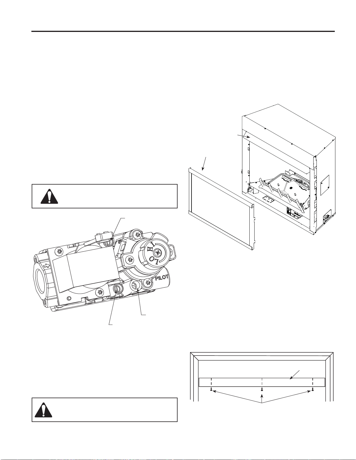
Figure 13 –
IPI Valve
Pressure Inlet
Pilot Adjust-
ment Screw
Pressure
Outlet
FP3034
FINAL INSTALLATION
REMOVE SCREEN
NOTE: Fireplace screen must be removed to access log
box and to install canopy.
Figure 14
1. Remove bottom access panel.
2. Removing fi replace screen frame panel by pushing
screen frame panel up and out.
Figure 14 -
Remove Fireplace Screen Panel
INSTALL CANOPY
Figure 15
1. Align the black canopy with the holes in the top frame
assembly.
2. Install the three (3) screws (in owner’s manual packag-
ing) which attach the canopy to the top frame assembly.
3. Tighten all screws. Make sure the canopy is level and
secure.
Canopy
Figure 15 -
Install Canopy
WARNING: Do not operate the unit with-
out the screen frame panel and canopy
installed.
Screws
Fireplace
Screen
Canopy
WARNING: Do NOT use open fl ame
to check for gas leaks.
Loading ...
Loading ...
Loading ...