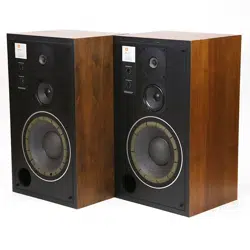
Page 2 - English - :
Connecting the L50
Adjusting the System
Power Capacity
Components
Component Removal
Replacement
For Additional Information
Specifications
Amann OTS WNP
Page 3 - English - :
The L50 is a direct result of the thorough. innovative engineering that produced the remarkable JBL L212 and
L110. Because it incorporates many of their technical advances—for instance. a crossover network closely approximating that of the L110—it delivers much of the exceptional spaciousness and clarity found in its more costly predecessors.
The design of every JBL product is based on a balanced consideration of laboratory instrument readings and the subjective reactions of the human ear. The L50 was developed using the most modern techniques available; for example. computer modeling and advanced laser interferometry. JBL engineers then subjected the proposed system to a series of critical auditions by a select panel. The resulting L50 offers a sonic image of unusual precision. spaciousness. solidity. and depth.
To connect loudspeaker systems placed up to 15 m (50 ft) CONNECTING THE L50 from the amplifier. +-mm (#18 AWG) insulated wire
(ordinary household lamp cord) is the minimum size recommended. For greater distances. heavier wire is desirable: 1.3 mm (#16 AWG) for distances up to 30 m
(100 ft) and 1.6 mm (#14 AWG) for distances up to
60 m (200 ft).
Page 4 - English - :
Connections to the loudspeaker system are made at the two terminals located on the back of the enclosure. The terminals will accept stranded or solid wire up to 2mm
(#12 AWG).
For each loudspeaker system. connect the wire from the black terminal to the amplifier output terminal labeled
“common. “ground. (—). or colored black. and the wire from the red terminal to the amplifier terminal labeled “8 ohms. “8 0. (+). or colored red. If lamp cord is used. the two wires can be told apart by noting that one of the insulating jackets is smooth. while the other has a distinct ridge. Connecting both systems as described will ensure in-phase operation; i.e. their cones will respond toa monophonic signal by moving simultaneously in the same direction. and not opposite to each other. (Note: Some amplifiers have a chassis grounding terminal. which is usually isolated from the other connectors. This should not be confused with the “ground” designation sometimes used to describe one of the terminals in each set of loudspeaker connections.)
The specified 8-ohm impedance rating is a nominal figure which suggests a connection giving the most efficient power transfer between amplifier and loudspeaker
1. Strip approximately 20 mm (% in) of the insulation from the end of the wire. Twist the wire strands together.
2. Turn the terminal counter-clockwise to the open position. insert the wire. then turn the terminal clockwise until the wire is secured. Rotate the terminal by hand—do not force tt.
Although JBL loudspeaker systems have wide dispersion. their sound is affected by their location. For instance. bass response will be augmented if the enclosures are placed near adjoining room surfaces (Le. in a corner. or on a wall near the floor or ceiling). Experiment before deciding on a final location for each system.
For the best possible stereo performance. the two loudspeaker systems should be arranged symmetrically on each side of the listener. As a general rule. a person sitting in the usual listening position should be at the apex of an angle of 40° between the two systems. The distance from one enclosure to the other should be determined by their distance from the listener and by this 40° listening angle.
Page 5 - English - :
Locating the high frequency driver at ear level usually gives the best results.
Note: Vertical orientation of the L50 is preferred for smoothest performance and best stereo imaging.
40° Listening Angle
Sound from each loudspeaker blends to form a stereo “image.”
The stereo image will be intensified and the area of best stereo perception increased if the two systems are turned slightly toward the preferred listening location.
The crossover network installed in the L50 is provided ADJUSTING THE SYSTEM with High Frequency Level and Mid Frequency Level controls to compensate for listening room acoustics by adjusting the output of the high frequency and midrange loudspeakers. When the controls are set at “5” the loudspeaker system will give balanced performance in a reverberation-free environment. Because all listening rooms possess some degree of absorption and reflection. alternate settings may produce more realistic tonal balance.
The L50 should be adjusted while playing typical program material with the preamplifier or receiver tone controls set at the flat response position. Begin by placing both of the loudspeaker system controls at 5. Turning the controls to the left will diminish high frequency and midrange level; turning them to the right will increase response in these ranges. Once the controls have been set for the most pleasing overall results. compensation for differences in program material should be made with the tone controls on the preamplifier or receiver.
Page 6 - English - :
High Frequency Level and Mid Frequency Level controls are located on the front of the enclosure. behind the removable grille.
POWER CAPACITY The specified power capacity indicates the continuous program power that the L50 will accept. Its remarkable transient response points to a considerably greater peak power capacity.
A number of loudspeaker systems can handle large amounts of power; others are highly efficient. JBL products are unique in their ability to combine both attributes. The
L50 produces sound at comfortable listening levels when driven by an amplifier having an output of as little as 10 watts continuous sine wave per channel* However. for reproduction of the full dynamic range of contemporary recordings. a high quality amplifier delivering up to 60 watts continuous sine wave per channel will provide the best performance. Such an amplifier has the reserve power necessary for accurate reproduction of transients. which can reach momentary peaks equivalent to ten times the average power level.
*The continuous sine wave rating of amplifier power is the most stringent method currently used in the audio industry. Many amplifier manufacturers use the term “watts rms" as a dtrect equivalent to the more meaningful watts continuous sine
Page 7 - English - :
The L50 enclosure panels are made of dense compressed ENCLOSURE wood. superior to solid wood in its acoustic properties. The veneer on the four side panels is solid American black walnut. To achieve the greatest strength and resistance to vibration. all panels are made of 19-mm (34-in) or 25-mm
(1-in) stock. and all joints are hand-fitted and woodwelded.
The enclosure features a hand-rubbed oil finish. As the oil penetrates into the walnut. the veneer may appear to be drying out. Many owners therefore re-oil the enclosure from time to time. With each application of oil the beauty of the finish will be enhanced. and a rich. warm patina will eventually appear.
To re-oil the enclosure. use any of the several clear oil finishing preparations available at furniture or hardware stores. Apply a liberal amount of the oil over the entire surface of the veneer. After fifteen minutes. wipe the surface with a clean. soft. dry cloth.
Small surface scratches can usually be removed by gently rubbing them out with #4/0 steel wool and applying oil to the entire panel. When using steel wool. use very light pressure and rub only in the direction of the grain. Deep scratches or serious damage should be repaired only by a qualified furniture refinisher.
Every component of every JBL loudspeaker system is COMPONENTS designed and produced to the most rigorous standards in the audio industry:
JBL loudspeaker frames are massive cast structures. machined to exacting tolerances.
Loudspeaker System Components
250-mm (10-in) Low Frequency Loudspeaker
130-mm (5-in) Midrange Loudspeaker
25-mm (1-in) High Frequency Loudspeaker
Page 8 - English - :
Magnetic assemblies are precisely manufactured of lowreluctance iron. energized by large. high grade magnets.
Voice coils are held within one turn of design specifications.
Cones are designed for the best possible combination of stiffness. density. and weight.
Each individual component. the enclosure. and finally the system as a whole must withstand a series of rigorous quality control tests and inspections.
LOW FREQUENCY —Extensive research resulted in a new
250-mm (10-in) loudspeaker with a 100-mm (4-in) center dome. This driver employs a 50-mm (2-in) voice coil and
1. 1kg (212 Ib) magnetic assembly energized by a powerful
Alnico V magnet. The voice coil is large and the magnetic assembly massive in comparison to most loudspeakers of this size. resulting in increased efficiency and superior transient response.
At higher frequencies. energy is coupled to the center dome. Radiation from the dome’s smaller area (relative to the total area of the cone) maintains smooth response and wide dispersion to frequencies far higher than the primary operating range of the driver. essential for smooth transition to the midrange loudspeaker.
A unique fiberglass acoustic resistance shell matches the loudspeaker’s characteristics to the enclosure volume.
Placed behind the loudspeaker. it provides optimum damping without restricting normal cone movement. The result is a less pronounced impedance peak and more nearly linear frequency response throughout the bass
MIDRANGE —The 130-mm (5-in) midrange loudspeaker. housed within an isolated sub-chamber to prevent detrimental interaction with the low frequency loudspeaker. delivers undistorted reproduction even at extreme volume levels. Its 22-mm (7s-in) diameter copper voice coil is unusually large in relation to cone size. yielding exceptional transient response and efficiency. A very stiff cone reduces the possibility of cone breakup at very high power levels. The aluminum center dome provides smooth frequency response through the transition to the high frequency loudspeaker. Because the midrange loudspeaker is considerably more efficient than the low frequency loudspeaker. it operates well below its full potential. maintaining the substantial reserve dynamic range necessary to reproduce high intensity program peaks without strain or distortion.
Page 9 - English - :
HIGH FREQUENCY — Exceptionally open high frequency reproduction is provided by a 36-mm (1.4-in) loudspeaker.
Despite its large magnetic assembly and voice coil. the diameter has been kept small to achieve excellent dispersion. The cone compliance is surrounded by a hard. sloped surface that serves as a transition to the enclosure baffle. eliminating discontinuities and diffraction effects.
This method of coupling the high frequency loudspeaker to the baffle has proved to be more effective than the use of sound absorbent material.
FREQUENCY DIVIDING NETWORK —The signal from the amplifier encompasses a wide range of frequencies. The frequency dividing network transmits each portion of the audio spectrum to the appropriate component of the loudspeaker system. Smooth. imperceptible operation of the network is vitally important.
The L50 network incorporates impedance-leveling and phase correcting circuitry. ensuring that the system operates in a nearly ideal manner through the transition frequencies. This circuitry. combined with the extended frequency response of the individual drivers. gives the sound of the L50 its startling transparency.
Should your JBL loudspeaker system require service. SERVICE return it to the JBL dealer from whom it was purchased. If this is not possible. write directly to the JBL Customer
Service Department. describing the problem as fully as possible. Products returned to the factory must be sent prepaid to JBL Customer Service Department. 8500 Balboa
Boulevard. Northridge. California 91329 U.S.A.
Should it become necessary to remove the loudspeaker COMPONENT REMOVAL system components for testing or repair. disconnect the system from the amplifier or receiver and proceed as
GRILLE —The grille is secured to the enclosure by dowel pins located near the corners of the enclosure. To remove the grille. grasp it by the top or bottom corners and pull gently. To replace the grille. re-position it on the enclosure and press lightly to re-seat it on the dowel pins. The JBL emblem can be turned to read correctly whether the system is positioned vertically or horizontally. .
LOUDSPEAKERS —The three loudspeakers are mounted from the front of the baffle panel and held in place by
Phillips-head screws. Carefully remove the screws; then lift the edge of the loudspeaker frame gently from the baffle panel. disconnect the wires at the push connectors. and remove the loudspeaker from the enclosure. Remove the
Page 10 - English - :
REPLACEMENT
FOR ADDITIONAL
INFORMATION
SPECIFICATIONS acoustic resistance shell from behind the low frequency loudspeaker and set it aside.
DIVIDING NETWORK —The dividing network is installed behind the baffle panel. held in place by four screws. To reach it: Remove the midrange and low frequency loudspeakers. Then take the wire leads out of the midrange sub-chamber. carefully pull the serialized foil nameplate from the network. and disconnect the input leads from the connectors at the back of the enclosure. Remove the mounting screws and lift the network out through the low frequency loudspeaker opening. (Note: Because the nameplate is often destroyed during removal. it is not recommended that the network be removed simply for inspection. If the network must be returned for service. enclose the nameplate; a new serialized nameplate will be provided.)
Reverse the removal procedure to replace the loudspeaker system components. Mounting screws should be tightened evenly in several stages to avoid warping the frame. and only enough to prevent air leaks between the components and the enclosure. Avoid using excessive
If you have difficulty in achieving the fine performance of which your JBL loudspeaker system is capable. consult the JBL dealer from whom the system was purchased. He has the knowledge required to provide expert advice and assistance. If for some reason the JBL dealer is unable to assist you. write directly to the JBL Technical Services
Department. explaining the difficulty in detail.
JBL continually engages in research related to product improvement. New materials. production methods. and design refinements are introduced into existing products without notice as a routine expression of this philosophy.
For this reason. any current JBL product may differ in some respect from its published description but will always equal or exceed the original design specifications unless otherwise stated.
JBL has traditionally refrained from publishing data for which no widely accepted test procedure has been established. In the absence of such standards. any laboratory can legitimately produce a variety of values. depending on the conditions selected.
Page 11 - English - :
Low Frequency Loudspeaker
Nominal Diameter 250 mm 10in
Voice Coil 50-mm (2-in) copper
Magnetic Assembly Weight L1kg 2.5 Ib
Flux Density 0. 5 tesla (8500 gauss)
Sensitivity’ 88 dB SPL. 1 watt. 1m (3.3 ft)
Midrange Loudspeaker
Nominal Diameter
130 mm 5in
Voice Coil
Magnetic Assembly Weight
22-mm (%-in) copper
0.74 kg 154 Ib
Flux Density 1.4 tesla (14. 00 gauss)
Sensitivity? 91 dB SPL. 1 watt. 1m (3.3 ft)
High Frequency Loudspeaker
Nominal Diameter 36mm 1¥2 in
Voice Coil 16-mm (%-in) copper
Magnetic Assembly Weight 0.74 kg 1 lb
Flux Density 1.5 tesla (15. 00 gauss)
Sensitivity? 91dB SPL. 1 watt. 1m (3.3 ft)
Nominal Impedance 8 ohms
Crossover Frequencies 800 Hz. 3 kHz
System Sensitivity+ 88 dB SPL. 1 watt. 1m (3.3 ft)
Power Capacity® 35 watts continuous program
Finish Oiled Walnut
Grille Colors Blue. brown. rust
Dimensions 622 mmx362 mmx314 mm
244/2 in X 14% in X 121732 in
Shipping Weight 21ikg 47 Ib
1. Averaged from 100 Hz to 500 Hz. within 1dB.
2. Averaged from 1kHz to 3 kHz. within 1 dB.
3. Averaged above 2 kHz. within 1dB.
4. All sensitivities are measured under hemispherical free-field conditions. Ina room. an additional 1 to 3 dB would be realized.
5. See Power Capacity section for amplifier power recommendations.
Page 12:
LOUDSPEAKER WIRING DIAGRAM
LOW FREQUENCY
DIVIDING NETWORK
INPUT TERMINALS
(REAR OF ENCLOSURE)